EP4385930B1 - Aufzug - Google Patents
Aufzug Download PDFInfo
- Publication number
- EP4385930B1 EP4385930B1 EP22213992.5A EP22213992A EP4385930B1 EP 4385930 B1 EP4385930 B1 EP 4385930B1 EP 22213992 A EP22213992 A EP 22213992A EP 4385930 B1 EP4385930 B1 EP 4385930B1
- Authority
- EP
- European Patent Office
- Prior art keywords
- lever
- pivot
- pivot lever
- car
- elevator
- Prior art date
- Legal status (The legal status is an assumption and is not a legal conclusion. Google has not performed a legal analysis and makes no representation as to the accuracy of the status listed.)
- Active
Links
Images



Classifications
-
- B—PERFORMING OPERATIONS; TRANSPORTING
- B66—HOISTING; LIFTING; HAULING
- B66B—ELEVATORS; ESCALATORS OR MOVING WALKWAYS
- B66B5/00—Applications of checking, fault-correcting, or safety devices in elevators
- B66B5/02—Applications of checking, fault-correcting, or safety devices in elevators responsive to abnormal operating conditions
- B66B5/04—Applications of checking, fault-correcting, or safety devices in elevators responsive to abnormal operating conditions for detecting excessive speed
-
- B—PERFORMING OPERATIONS; TRANSPORTING
- B66—HOISTING; LIFTING; HAULING
- B66B—ELEVATORS; ESCALATORS OR MOVING WALKWAYS
- B66B5/00—Applications of checking, fault-correcting, or safety devices in elevators
- B66B5/02—Applications of checking, fault-correcting, or safety devices in elevators responsive to abnormal operating conditions
- B66B5/16—Braking or catch devices operating between cars, cages, or skips and fixed guide elements or surfaces in hoistway or well
- B66B5/18—Braking or catch devices operating between cars, cages, or skips and fixed guide elements or surfaces in hoistway or well and applying frictional retarding forces
Definitions
- the invention relates to an elevator according to the preamble of claim 1.
- elevators are equipped with safety gears.
- the cause of an impermissibly high acceleration of the car can be, for example, a malfunction of the control system of a drive or its brake or a rope break.
- the detection of an impermissibly high speed and the subsequent necessary triggering of the safety gear is typically carried out with the aid of a so-called overspeed governor.
- the pivot lever 42 is connected in a rotationally fixed manner to the synchronizing element 41, which is designed as a shaft.
- This synchronizing element 41 transmits the pivoting movement of the pivot lever 42 to a second pivot lever 42 arranged parallel to this first pivot lever 42 (which is not shown in Fig. 2 ).
- this problem is typically solved by means of a connecting member 43.
- This connecting member 43 is connected, for example by a pin connection, to the pivot lever 42 and the clamping body in such a way that a rotational movement of the pivot lever 42 relative to the connecting member 43 is possible, as well as a rotational movement of the connecting member 43 relative to the clamping body.
- This allows the pivot lever 42 to perform a purely rotational movement about the pivot axis 47, while the clamp body performs a purely translational movement with respect to the pivot axis 47.
- the pivot lever 42 is positioned laterally next to the safety gear 3 and thus with some offset from the center of gravity of the clamping body.
- the braking force (occurring at the first contact of the clamping body with the guide rail 46 at the clamping body, pulling it further into the wedge gap between the guide rail 46 and the safety gear 3).
- to shear forces between the connecting member 43 and the clamping body as well as between the connecting member 43 and the pivot lever 42 These shear forces cause an increase in the already described sag of the pivot lever 42, which is not controlled by the activating element 48.
- the arrangement of the pivot lever 42 with an offset with respect to the centre of gravity of the clamping body affects the rigidity of the structure and, consequently
- US 2007/181378 A1 discloses the preamble of claim 1. It relates to an emergency stop system for an elevator.
- a governor sheave that moves in synchronism with the raising and lowering of a car is wound around a governor sheave.
- the car is mounted with a safety device for braking the car through displacement of the car, which is connected to the governor rope, with respect to the governor rope.
- a control device outputs an activation signal upon detecting an abnormality in the speed of the car.
- a rope catching device is provided in the vicinity of the governor sheave.
- the rope catching device has an electromagnetic actuator that is activated upon input of the activation signal, and a restraining portion for restraining the governor rope upon the activation of the electromagnetic actuator.
- the solution to the problem involves an elevator having a car and at least two safety gears mounted remotely from each other on the car and a preferably broadly understood overspeed governor - preferably exactly one overspeed governor.
- the elevator comprises an activating element controlled by the overspeed governor to apply a brake actuation force in the event of overspeed, preferably in the form of a traction force.
- This brake actuating force is transmitted to the safety gears via a synchronizing device for synchronous triggering.
- the synchronizing device has a pivot lever for each safety gear.
- the pivot lever is hinged at one end to the clamping body of the safety gear in a hinge area. On the opposite other side, it is connected to another pivot lever via a synchronizing element.
- the other pivot lever is associated with another safety gear.
- the elevator is characterized by the fact that a translatory movement relative to its pivot axis is superimposed on the pivot levers or their rotating movement. This translatory movement causes said hinge area of the respective pivot lever to perform a resulting movement that is translatory.
- the resulting movement of the hinge area of the pivot lever regularly runs at least essentially parallel to the direction of insertion of the clamping body into the wedge gap assigned to it.
- the two pivot levers are ideally connected to each other indirectly via one or more further elements of the synchronizing device, so that the two pivot levers together with the safety gears controlled by them can be arranged on two opposite sides of the car. This ensures a uniform application of force to the car during the triggering of the safety gears.
- the "car” is understood to be either an essentially non-self-supporting car which is accommodated in a supporting sling, i.e. a supporting frame, or a car with an integrated car frame, the integration of which replaces the sling, or simply a platform which can be moved in the shaft for parking the goods to be transported.
- “Hinged” means a connection that allows the pivot lever on the clamping body to make the movement required to engage the brake.
- the “hinge area" of the pivot lever is the section of the pivot lever via which it is connected to the clamping body of the safety gear.
- the hinge area thus corresponds to the section of the pivot lever in which the pin is arranged.
- a synchronizing device which preferably has features according to the synchronizing device of an elevator according to the invention. It is used for synchronous triggering of a plurality of safety devices on an elevator car.
- the synchronizing device is characterized by the fact that it has at least two pivot levers, each of which can be pivoted about at least one stationary pivot axis on the car.
- the pivot levers act on at least two safety gears.
- the safety gears are actuated by a synchronizing shaft which transmits essentially only torsion and is itself not translationally movable, the rotation of which controls the pivot levers.
- the pivot lever is actuated by a coupling lever during triggering.
- the pivot lever and the coupling lever also move translationally relative to each other in their coupling area during triggering.
- the pivot lever and the coupling lever are coupled in that an axle pin of one of these levers is movably held in a straight slot of the other of these levers.
- the pivot lever is designed in the form of a telescopic rod and the translatory relative movement is effected by the extension and retraction of the telescopic rod.
- the generation of the translatory relative movement by means of an axle pin of one lever which is held in a straight slot of the other lever is advantageous, since the translatory mobility of the one lever is particularly easily advanced.
- the length of the straight slot determines the maximum translatory freedom of movement.
- the translatory relative movement of the two levers with respect to each other can also take place simultaneously with a pivoting movement of the two levers with respect to each other.
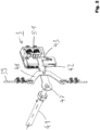
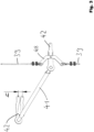
- the axle pin 23 performs a movement composed of a rotational movement and of a translational movement. This is illustrated with reference to the arrows 54 and 55 in Fig. 7 . Since the axle pin 23 protrudes through a bore 36 of the pivot lever 18, the movement of the axle pin 23 is transmitted to the pivot lever 18.
- the straight slot 12 is provided in the arm of the coupling lever 11. Although not preferred, there are also cases in which the straight slot 12 is instead provided in the torsion bar, in the area of one of its ends. Said straight slot causes the pivot lever 18 to perform both a rotational movement about its pivot axis 21 and a translational movement dictated by the movement of the axle pin 23. This is possible because the pivot lever 18 has an oblong hole 38 in the area where the pin 28, which predetermines the pivot axis 21 of the pivot lever 18, protrudes through the pivot lever 18. Relative to the pin 28, the pivot lever 18 thus performs both a translational movement and a rotational movement in the clockwise direction, as illustrated by the arrows 56 and 57 in Fig. 7 .
- the pivot lever 18 is connected to the clamping body 4 of a safety gear 3 via an axle pin 25. This connection is such that the pivot lever 18 can rotate relative to the clamping body 4 about the axle pin 25, but otherwise imposes its movement on the clamping body 4.
- This second pivot lever is actuated, in the same way as the first pivot lever 18, by a second coupling lever.
- This second coupling lever performs the same movement as the first coupling lever 11.
- the second coupling lever is not actuated by an activating element, although this would also be a conceivable embodiment of the synchronizing device 9 according to the invention.
- the movement of the second coupling lever is generated by means of the synchronizing element 10 designed as a shaft.
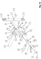
- the first coupling lever 11 is flanged to the synchronizing element 10 by means of two screws 32.
- This causes the synchronizing element 10 to perform a rotational movement about the axis of rotation 13, which is also the longitudinal axis of the synchronizing element 10. Since the second coupling lever is flanged to the synchronizing element 10 in the same way as already the first coupling lever 11, this leads to a corresponding rotational movement of the second coupling lever, namely in synchronism with the rotational movement of the first coupling lever 11.
- the second pivot lever is moved so that it engages the clamping body of the second safety gear with the second guide rail.
- the synchronizing element 10 is secured to the car frame 2 by means of two tabs 24 such that it can perform a rotation about their longitudinal axis, but cannot perform a translational relative movement to the car frame 2 in or against the direction of movement of the car 2 along the elevator shaft.
- a tension spring 26 is provided. This tension spring is attached at one end to the safety gear 3 and at its other end to one of the through bores 35 of the pivot lever 18.
- the coupling lever 11 is connected to the activating element 8 by means of the screw 29.
- the screw 29 is inserted both through the bore 31 of the activating element 8 and through the bore 30 of the coupling lever 11. Then it is screwed - mostly on the side of the coupling lever 11 facing away from the activating element 8 - with a nut.
- the coupling lever 11 is connected to the synchronizing element 10 by screwing the screws 32 through the arc slots 17 into the bores 34 of the flange 33.
- the coupling lever 11 is centred on the synchronizing element 10 by means of the shaft shoulder 52 forming a bearing seat, onto which the coupling lever 11 is pushed with its bearing eye 49.
- the activating element 8 engages the first coupling lever 11 and not the first pivot lever 18, it is ensured that any sagging of the second pivot lever - if it occurs - can also be observed at the first pivot lever 18. Accordingly, even in the event that the pivot levers were to sag, the triggering of the safety gears would be synchronous. However, in the embodiment of the synchronizing device 9 shown, sagging of the pivot levers does not take place anyway, or only to a negligible extent. This will be explained below with reference to the first pivot lever 18.
- the pivot lever 18 does not (mainly) rotate about the longitudinal axis of the synchronizing element 10 like the pivot levers known from the prior art, but about an additional pivot axis 21, the torque counteracting the pivoting movement of the pivot lever 18 is significantly reduced - i.e. the torque resulting from the dead weight of the pivot lever 18 and the weight of the clamping body 4.
- the pivot axis 21 is allowed to move closer to the resulting point of application of the weight force, so that the lever arm is smaller.
- the pivot arm 18 has a lesser tendency to counteract the rotational movement of the synchronizing element 10 or the coupling lever 11, which ultimately results in a significantly reduced sag of the pivot lever 18. This applies both to the first pivot lever 18 and to the second pivot lever opposite thereto.
- the synchronizing device 9 can in principle also be used to trigger the safety gears when the car 2 moves upwards too quickly. For this purpose, it is only necessary to provide safety gears whose clamping body, starting from the initial position, can be brought into engagement with the guide rail both by a downward movement (relative to the rest of the safety gear) and by an upward movement. When such safety gears are used, the synchronizing device 9 can then be mounted so that the pivot lever 18 and the coupling lever 11 are arranged in their initial position such that their central longitudinal axes 22 and 14 are approximately coaxial with each other. Depending on whether the activating element 8 is then pulled upwards or downwards by the governor rope braked by the safety gear, the pivoting movement of the pivot lever 18 then takes place in clockwise or counterclockwise direction.
- Such a pivot lever designed as a "lever cascade” is suitable for bridging a large distance between the safety gear 3 and the activating element 8 without at the same time causing a significant increase in the lever arm effect. This is of particular importance for suspension belt lifts, where larger distances naturally have to be bridged without having to build special safety gears for this purpose.
Landscapes
- Engineering & Computer Science (AREA)
- Mechanical Engineering (AREA)
- Maintenance And Inspection Apparatuses For Elevators (AREA)
Claims (15)
- Ein Aufzug (1) mit einer Kabine (2) und mindestens zwei Sicherheitsvorrichtungen (3), die in einem Abstand voneinander an der Kabine (2) montiert sind, sowie einem Geschwindigkeitsbegrenzer mit einem durch den Geschwindigkeitsbegrenzer gesteuerten Auslöseelement (8), welches im Falle einer Übergeschwindigkeit eine Bremsbetätigungskraft, vorzugsweise in Form einer Zugkraft, aufbringt, die über eine Synchronisiereinrichtung (9) zur synchronen Auslösung auf die Sicherheitsvorrichtungen (3) übertragen wird, wobei die Synchronisiereinrichtung (9) für jede Sicherheitsvorrichtung (3) einen Schwenkhebel (18) aufweist, der an seinem einen Endbereich in einem Schwenkbereich (20) am Klemmkörper (4) der Sicherheitsvorrichtung (3) angelenkt ist und auf der anderen Seite über ein Synchronisierelement (10) mit einem anderen Schwenkhebel (18) verbunden ist, der einer anderen Sicherheitsvorrichtung (3) zugeordnet ist, dadurch gekennzeichnet, dass den Schwenkhebeln (18) relativ zu ihrer Schwenkachse (21) eine translatorische Bewegung überlagert ist, wodurch der jeweilige Schwenkbereich (20) des entsprechenden Schwenkhebels (18) eine resultierende Bewegung ausführt, die translatorisch ist.
- Der Aufzug (1) nach Anspruch 1, dadurch gekennzeichnet, dass der Schwenkhebel (18) bei der Auslösung durch einen Kupplungshebel (11) betätigt wird, wobei der Schwenkhebel (18) und der Kupplungshebel (11) auch während der Auslösung relativ zueinander in ihrem Kupplungsbereich translatorisch gekoppelt sind, und vorzugsweise dadurch, dass ein Achszapfen (23) eines dieser Hebel (11, 18) beweglich in einem geraden Schlitz (12) des anderen dieser Hebel (11, 18) gehalten ist.
- Der Aufzug (1) nach Anspruch 2, dadurch gekennzeichnet, dass die beiden Hebel (11, 18) stets in entgegengesetzte Richtungen schwenken.
- Der Aufzug (1) nach einem der vorhergehenden Ansprüche, dadurch gekennzeichnet, dass der Schwenkhebel (18) derart schwenkbar auf einer kabinenfesten Achse (21) gelagert ist, dass der Schwenkhebel (18) zusätzlich eine translatorische Bewegung relativ zu seiner kabinenfesten Achse (21) ausführen kann.
- Der Aufzug (1) nach einem der Ansprüche 2 bis 4, sofern Anspruch 2 zugrunde liegt, dadurch gekennzeichnet, dass der Kupplungshebel (11) um eine weitere geometrische kabinenfeste Achse (13) rotiert, ohne dass dieser relativ zu dieser Achse (13) eine zusätzliche translatorische Bewegung ausführen kann.
- Der Aufzug (1) nach Anspruch 5, dadurch gekennzeichnet, dass die kabinenfeste Rotationsachse (13) für den Kupplungshebel (11) durch ein Ende des Synchronisierelements (10) gebildet ist, das seinerseits schwenkbar an der Kabine (2) oder am Kabinenrahmen (2) gelagert ist, vorzugsweise durch eine Lasche (24), die am Kabinenrahmen (2) montierbar ist.
- Der Aufzug (1) nach einem der Ansprüche 2 bis 6, sofern Anspruch 2 zugrunde liegt, dadurch gekennzeichnet, dass die Synchronisiereinrichtung (9) die Sicherheitsvorrichtungen (3) bidirektional aktivieren kann, d.h. sowohl bei Abwärts- als auch bei Aufwärtsfahrten, vorzugsweise aus einer Bereitschaftsstellung heraus, in der die größten zentralen Längsachsen (22, 14) des Schwenkhebels (18) und des Kupplungshebels (11) ausgerichtet sind, wobei der Kupplungshebel (11) aus seiner Bereitschaftsstellung entweder im Uhrzeigersinn oder entgegen dem Uhrzeigersinn schwenkbar ist, wodurch der Schwenkhebel (18) gegen den Uhrzeigersinn bzw. im Uhrzeigersinn schwenkt.
- Der Aufzug (1) nach Anspruch 6 oder 7, dadurch gekennzeichnet, dass das Synchronisierelement (10) eine Welle (10) ist, die im Wesentlichen nur einer Torsion unterliegt, deren Drehung die Schwenkhebel (18) über die Kupplungshebel (11) steuert.
- Der Aufzug (1) nach Anspruch 8, dadurch gekennzeichnet, dass diese Welle (10) zumindest an einem Kupplungshebel (11) so angeflanscht ist, dass der Kupplungshebel (11) in unterschiedlichen Drehpositionen an der Welle (10) fixierbar ist.
- Der Aufzug (1) nach einem der vorhergehenden Ansprüche, dadurch gekennzeichnet, dass der Schwenkhebel (18) direkt am Klemmkörper (4) angelenkt ist und zu diesem Zweck mit dem Klemmkörper (4) verbunden ist - vorzugsweise über einen Achszapfen (25).
- Der Aufzug (1) nach dem unmittelbar vorhergehenden Anspruch, dadurch gekennzeichnet, dass der Schwenkhebel (18) durch eine Öffnung (6) des Sicherheitsvorrichtungsgehäuses (5) bis in das Sicherheitsvorrichtungsgehäuse (5) hineinragt, um dort mit dem Klemmkörper (4) zusammenzuwirken.
- Der Aufzug (1) nach einem der Ansprüche 2 bis 11, sofern Anspruch 2 zugrunde liegt, dadurch gekennzeichnet, dass der Schwenkhebel (18) Armabschnitte (19) aufweist, die in entgegengesetzte Richtungen von der kabinenfesten Achse (21) weg verlaufen, um die der Schwenkhebel (18) schwenkt, und/oder dass der Kupplungshebel (11) Armabschnitte (19) aufweist, die in entgegengesetzte Richtungen von der kabinenfesten Achse (13) weg verlaufen, um die der Kupplungshebel (11) schwenkt.
- Der Aufzug (1) nach einem der Ansprüche 2 bis 12, sofern Anspruch 2 zugrunde liegt, dadurch gekennzeichnet, dass der Schwenkhebel (18) eine größere Ausdehnung entlang seiner Hauptlängsachse (22) aufweist als der Kupplungshebel (11) entlang seiner Hauptlängsachse (14).
- Der Aufzug (1) nach einem der Ansprüche 2 bis 13, sofern Anspruch 2 zugrunde liegt, dadurch gekennzeichnet, dass der Kupplungshebel (11) eine Kreuzform aufweist, vorzugsweise mit zwei langen Armen (15) - die sich in der Regel diametral gegenüber dem Lagerauge (49) des Kupplungshebels (11) befinden - und zwei kurzen Armen (16) - die sich in der Regel diametral gegenüber dem Lagerauge (49) des Kupplungshebels (11) befinden - wobei vorzugsweise ein langer Arm (15) einen geraden Schlitz (12) aufweist und vorzugsweise beide kurzen Arme (16) jeweils mindestens einen Bogenschlitz (17) aufweisen.
- Der Aufzug (1) nach einem der vorhergehenden Ansprüche, dadurch gekennzeichnet, dass mindestens eine Feder (26) zur Rückführung des Schwenkhebels (18) in seine Bereitschaftsstellung vorgesehen ist, welche Feder vorzugsweise zwischen dem Gehäuse (5) einer Sicherheitsvorrichtung (3) und dem Schwenkhebel (18) aufgehängt ist.
Priority Applications (4)
| Application Number | Priority Date | Filing Date | Title |
|---|---|---|---|
| EP22213992.5A EP4385930B1 (de) | 2022-12-15 | 2022-12-15 | Aufzug |
| HUE22213992A HUE071221T2 (hu) | 2022-12-15 | 2022-12-15 | Felvonó |
| ES22213992T ES3030011T3 (en) | 2022-12-15 | 2022-12-15 | Elevator |
| CN202311724901.0A CN117886192A (zh) | 2022-12-15 | 2023-12-14 | 电梯 |
Applications Claiming Priority (1)
| Application Number | Priority Date | Filing Date | Title |
|---|---|---|---|
| EP22213992.5A EP4385930B1 (de) | 2022-12-15 | 2022-12-15 | Aufzug |
Publications (2)
| Publication Number | Publication Date |
|---|---|
| EP4385930A1 EP4385930A1 (de) | 2024-06-19 |
| EP4385930B1 true EP4385930B1 (de) | 2025-04-02 |
Family
ID=84537380
Family Applications (1)
| Application Number | Title | Priority Date | Filing Date |
|---|---|---|---|
| EP22213992.5A Active EP4385930B1 (de) | 2022-12-15 | 2022-12-15 | Aufzug |
Country Status (4)
| Country | Link |
|---|---|
| EP (1) | EP4385930B1 (de) |
| CN (1) | CN117886192A (de) |
| ES (1) | ES3030011T3 (de) |
| HU (1) | HUE071221T2 (de) |
Family Cites Families (3)
| Publication number | Priority date | Publication date | Assignee | Title |
|---|---|---|---|---|
| WO2005102899A1 (ja) * | 2004-04-20 | 2005-11-03 | Mitsubishi Denki Kabushiki Kaisha | エレベータの非常止めシステム |
| CA2544664C (en) * | 2004-05-25 | 2011-06-14 | Mitsubishi Denki Kabushiki Kaisha | Safety device for an elevator |
| EP3670416B1 (de) * | 2018-12-20 | 2026-02-25 | Otis Elevator Company | Sicherheitsbremse für ein gegengewicht, aktivierbar durch ein tragmittel |
-
2022
- 2022-12-15 HU HUE22213992A patent/HUE071221T2/hu unknown
- 2022-12-15 ES ES22213992T patent/ES3030011T3/es active Active
- 2022-12-15 EP EP22213992.5A patent/EP4385930B1/de active Active
-
2023
- 2023-12-14 CN CN202311724901.0A patent/CN117886192A/zh active Pending
Also Published As
| Publication number | Publication date |
|---|---|
| EP4385930A1 (de) | 2024-06-19 |
| ES3030011T3 (en) | 2025-06-26 |
| HUE071221T2 (hu) | 2025-08-28 |
| CN117886192A (zh) | 2024-04-16 |
Similar Documents
| Publication | Publication Date | Title |
|---|---|---|
| JP5026743B2 (ja) | プログレッシブ安全装置 | |
| US4923055A (en) | Safety mechanism for preventing unintended motion in traction elevators | |
| EP2571799B1 (de) | Integriertes sicherheitssystem für einen aufzug | |
| US7681695B2 (en) | Method of modernizing the car door system of an elevator, and modernizing constructional set for carrying out the method | |
| US8720262B2 (en) | Testing a speed limiting system of an elevator installation | |
| US5310022A (en) | Mechanical overspeed safety device | |
| JP2002533281A (ja) | 電子式エレベータ安全システム | |
| EP2380840B1 (de) | Sicherheitsvorrichtung für einen aufzug | |
| JPS6363466B2 (de) | ||
| EP3147246B1 (de) | Betätigungsanordnung für ein aufzugfliehkraftregler-system und verfahren | |
| MX2007010365A (es) | Procedimiento para la operacion de una instalacion de ascensor, una instalcion de ascensor operable mediante dicho procedimiento, y un equipamiento de seguridad para esta instalacion de ascensor. | |
| US6942070B2 (en) | Emergency braking and shock absorbing device for a lift or suspended load | |
| AU2016231645A1 (en) | Braking system for a hoisted structure and method of controlling braking a hoisted structure | |
| EP3670416B1 (de) | Sicherheitsbremse für ein gegengewicht, aktivierbar durch ein tragmittel | |
| JP2000211841A (ja) | エレベ―タ装置の動きを停止させる装置 | |
| EP4385930A1 (de) | Aufzug | |
| WO2021239456A1 (en) | Devices for activating elevator safety brakes | |
| EP1086921B1 (de) | Aufzugssicherheitseinrichtung | |
| CN109775508B (zh) | 紧急制动装置及具有该紧急制动装置的电梯系统 | |
| US3346074A (en) | Flexible guide clamp safety | |
| EP3269672B1 (de) | Aufzugsgeschwindigkeitsregler | |
| CN223592179U (zh) | 具有张紧装置的凸轮双摆杆限速器 | |
| US20260109574A1 (en) | Electromechanical safety actuation of elevator governors | |
| CN119911774B (zh) | 轿架随动限速器及电梯 | |
| EP4617216B1 (de) | Vorrichtung zum betätigen und verriegeln von aufzugstüren |
Legal Events
| Date | Code | Title | Description |
|---|---|---|---|
| PUAI | Public reference made under article 153(3) epc to a published international application that has entered the european phase |
Free format text: ORIGINAL CODE: 0009012 |
|
| STAA | Information on the status of an ep patent application or granted ep patent |
Free format text: STATUS: THE APPLICATION HAS BEEN PUBLISHED |
|
| AK | Designated contracting states |
Kind code of ref document: A1 Designated state(s): AL AT BE BG CH CY CZ DE DK EE ES FI FR GB GR HR HU IE IS IT LI LT LU LV MC ME MK MT NL NO PL PT RO RS SE SI SK SM TR |
|
| STAA | Information on the status of an ep patent application or granted ep patent |
Free format text: STATUS: REQUEST FOR EXAMINATION WAS MADE |
|
| 17P | Request for examination filed |
Effective date: 20240912 |
|
| RBV | Designated contracting states (corrected) |
Designated state(s): AL AT BE BG CH CY CZ DE DK EE ES FI FR GB GR HR HU IE IS IT LI LT LU LV MC ME MK MT NL NO PL PT RO RS SE SI SK SM TR |
|
| GRAP | Despatch of communication of intention to grant a patent |
Free format text: ORIGINAL CODE: EPIDOSNIGR1 |
|
| STAA | Information on the status of an ep patent application or granted ep patent |
Free format text: STATUS: GRANT OF PATENT IS INTENDED |
|
| INTG | Intention to grant announced |
Effective date: 20241028 |
|
| GRAS | Grant fee paid |
Free format text: ORIGINAL CODE: EPIDOSNIGR3 |
|
| GRAA | (expected) grant |
Free format text: ORIGINAL CODE: 0009210 |
|
| STAA | Information on the status of an ep patent application or granted ep patent |
Free format text: STATUS: THE PATENT HAS BEEN GRANTED |
|
| AK | Designated contracting states |
Kind code of ref document: B1 Designated state(s): AL AT BE BG CH CY CZ DE DK EE ES FI FR GB GR HR HU IE IS IT LI LT LU LV MC ME MK MT NL NO PL PT RO RS SE SI SK SM TR |
|
| REG | Reference to a national code |
Ref country code: GB Ref legal event code: FG4D |
|
| REG | Reference to a national code |
Ref country code: CH Ref legal event code: EP |
|
| REG | Reference to a national code |
Ref country code: IE Ref legal event code: FG4D |
|
| REG | Reference to a national code |
Ref country code: DE Ref legal event code: R096 Ref document number: 602022012537 Country of ref document: DE |
|
| REG | Reference to a national code |
Ref country code: ES Ref legal event code: FG2A Ref document number: 3030011 Country of ref document: ES Kind code of ref document: T3 Effective date: 20250626 |
|
| REG | Reference to a national code |
Ref country code: SK Ref legal event code: T3 Ref document number: E 46375 Country of ref document: SK |
|
| REG | Reference to a national code |
Ref country code: NL Ref legal event code: MP Effective date: 20250402 |
|
| REG | Reference to a national code |
Ref country code: HU Ref legal event code: AG4A Ref document number: E071221 Country of ref document: HU |
|
| PG25 | Lapsed in a contracting state [announced via postgrant information from national office to epo] |
Ref country code: NL Free format text: LAPSE BECAUSE OF FAILURE TO SUBMIT A TRANSLATION OF THE DESCRIPTION OR TO PAY THE FEE WITHIN THE PRESCRIBED TIME-LIMIT Effective date: 20250402 |
|
| PG25 | Lapsed in a contracting state [announced via postgrant information from national office to epo] |
Ref country code: PT Free format text: LAPSE BECAUSE OF FAILURE TO SUBMIT A TRANSLATION OF THE DESCRIPTION OR TO PAY THE FEE WITHIN THE PRESCRIBED TIME-LIMIT Effective date: 20250804 Ref country code: FI Free format text: LAPSE BECAUSE OF FAILURE TO SUBMIT A TRANSLATION OF THE DESCRIPTION OR TO PAY THE FEE WITHIN THE PRESCRIBED TIME-LIMIT Effective date: 20250402 |
|
| REG | Reference to a national code |
Ref country code: LT Ref legal event code: MG9D |
|
| PG25 | Lapsed in a contracting state [announced via postgrant information from national office to epo] |
Ref country code: GR Free format text: LAPSE BECAUSE OF FAILURE TO SUBMIT A TRANSLATION OF THE DESCRIPTION OR TO PAY THE FEE WITHIN THE PRESCRIBED TIME-LIMIT Effective date: 20250703 Ref country code: NO Free format text: LAPSE BECAUSE OF FAILURE TO SUBMIT A TRANSLATION OF THE DESCRIPTION OR TO PAY THE FEE WITHIN THE PRESCRIBED TIME-LIMIT Effective date: 20250702 |
|
| PG25 | Lapsed in a contracting state [announced via postgrant information from national office to epo] |
Ref country code: PL Free format text: LAPSE BECAUSE OF FAILURE TO SUBMIT A TRANSLATION OF THE DESCRIPTION OR TO PAY THE FEE WITHIN THE PRESCRIBED TIME-LIMIT Effective date: 20250402 |
|
| PG25 | Lapsed in a contracting state [announced via postgrant information from national office to epo] |
Ref country code: BG Free format text: LAPSE BECAUSE OF FAILURE TO SUBMIT A TRANSLATION OF THE DESCRIPTION OR TO PAY THE FEE WITHIN THE PRESCRIBED TIME-LIMIT Effective date: 20250402 |
|
| PG25 | Lapsed in a contracting state [announced via postgrant information from national office to epo] |
Ref country code: HR Free format text: LAPSE BECAUSE OF FAILURE TO SUBMIT A TRANSLATION OF THE DESCRIPTION OR TO PAY THE FEE WITHIN THE PRESCRIBED TIME-LIMIT Effective date: 20250402 |
|
| PG25 | Lapsed in a contracting state [announced via postgrant information from national office to epo] |
Ref country code: RS Free format text: LAPSE BECAUSE OF FAILURE TO SUBMIT A TRANSLATION OF THE DESCRIPTION OR TO PAY THE FEE WITHIN THE PRESCRIBED TIME-LIMIT Effective date: 20250702 |
|
| PG25 | Lapsed in a contracting state [announced via postgrant information from national office to epo] |
Ref country code: IS Free format text: LAPSE BECAUSE OF FAILURE TO SUBMIT A TRANSLATION OF THE DESCRIPTION OR TO PAY THE FEE WITHIN THE PRESCRIBED TIME-LIMIT Effective date: 20250802 |
|
| PG25 | Lapsed in a contracting state [announced via postgrant information from national office to epo] |
Ref country code: LV Free format text: LAPSE BECAUSE OF FAILURE TO SUBMIT A TRANSLATION OF THE DESCRIPTION OR TO PAY THE FEE WITHIN THE PRESCRIBED TIME-LIMIT Effective date: 20250402 |
|
| REG | Reference to a national code |
Ref country code: CH Ref legal event code: U11 Free format text: ST27 STATUS EVENT CODE: U-0-0-U10-U11 (AS PROVIDED BY THE NATIONAL OFFICE) Effective date: 20260101 |
|
| REG | Reference to a national code |
Ref country code: DE Ref legal event code: R097 Ref document number: 602022012537 Country of ref document: DE |
|
| PG25 | Lapsed in a contracting state [announced via postgrant information from national office to epo] |
Ref country code: DK Free format text: LAPSE BECAUSE OF FAILURE TO SUBMIT A TRANSLATION OF THE DESCRIPTION OR TO PAY THE FEE WITHIN THE PRESCRIBED TIME-LIMIT Effective date: 20250402 Ref country code: SM Free format text: LAPSE BECAUSE OF FAILURE TO SUBMIT A TRANSLATION OF THE DESCRIPTION OR TO PAY THE FEE WITHIN THE PRESCRIBED TIME-LIMIT Effective date: 20250402 |
|
| PGFP | Annual fee paid to national office [announced via postgrant information from national office to epo] |
Ref country code: AT Payment date: 20260113 Year of fee payment: 4 |
|
| PGFP | Annual fee paid to national office [announced via postgrant information from national office to epo] |
Ref country code: HU Payment date: 20251212 Year of fee payment: 4 Ref country code: FR Payment date: 20251217 Year of fee payment: 4 |
|
| PGFP | Annual fee paid to national office [announced via postgrant information from national office to epo] |
Ref country code: TR Payment date: 20251209 Year of fee payment: 4 |
|
| PG25 | Lapsed in a contracting state [announced via postgrant information from national office to epo] |
Ref country code: CZ Free format text: LAPSE BECAUSE OF FAILURE TO SUBMIT A TRANSLATION OF THE DESCRIPTION OR TO PAY THE FEE WITHIN THE PRESCRIBED TIME-LIMIT Effective date: 20250402 |
|
| PG25 | Lapsed in a contracting state [announced via postgrant information from national office to epo] |
Ref country code: EE Free format text: LAPSE BECAUSE OF FAILURE TO SUBMIT A TRANSLATION OF THE DESCRIPTION OR TO PAY THE FEE WITHIN THE PRESCRIBED TIME-LIMIT Effective date: 20250402 |
|
| PGFP | Annual fee paid to national office [announced via postgrant information from national office to epo] |
Ref country code: SK Payment date: 20251209 Year of fee payment: 4 |
|
| PLBE | No opposition filed within time limit |
Free format text: ORIGINAL CODE: 0009261 |
|
| STAA | Information on the status of an ep patent application or granted ep patent |
Free format text: STATUS: NO OPPOSITION FILED WITHIN TIME LIMIT |
|
| REG | Reference to a national code |
Ref country code: CH Ref legal event code: L10 Free format text: ST27 STATUS EVENT CODE: U-0-0-L10-L00 (AS PROVIDED BY THE NATIONAL OFFICE) Effective date: 20260211 |
|
| PG25 | Lapsed in a contracting state [announced via postgrant information from national office to epo] |
Ref country code: RO Free format text: LAPSE BECAUSE OF FAILURE TO SUBMIT A TRANSLATION OF THE DESCRIPTION OR TO PAY THE FEE WITHIN THE PRESCRIBED TIME-LIMIT Effective date: 20250402 |
|
| 26N | No opposition filed |
Effective date: 20260105 |
|
| PGFP | Annual fee paid to national office [announced via postgrant information from national office to epo] |
Ref country code: ES Payment date: 20260119 Year of fee payment: 4 |
|
| PGFP | Annual fee paid to national office [announced via postgrant information from national office to epo] |
Ref country code: DE Payment date: 20251222 Year of fee payment: 4 |
|
| PGFP | Annual fee paid to national office [announced via postgrant information from national office to epo] |
Ref country code: IT Payment date: 20251231 Year of fee payment: 4 |
|
| PGFP | Annual fee paid to national office [announced via postgrant information from national office to epo] |
Ref country code: CH Payment date: 20260101 Year of fee payment: 4 |