EP4385927A1 - Thread cutting tool - Google Patents
Thread cutting tool Download PDFInfo
- Publication number
- EP4385927A1 EP4385927A1 EP23214890.8A EP23214890A EP4385927A1 EP 4385927 A1 EP4385927 A1 EP 4385927A1 EP 23214890 A EP23214890 A EP 23214890A EP 4385927 A1 EP4385927 A1 EP 4385927A1
- Authority
- EP
- European Patent Office
- Prior art keywords
- yarn
- paper tube
- operation part
- respect
- blade
- Prior art date
- Legal status (The legal status is an assumption and is not a legal conclusion. Google has not performed a legal analysis and makes no representation as to the accuracy of the status listed.)
- Granted
Links
Images



Classifications
-
- B—PERFORMING OPERATIONS; TRANSPORTING
- B65—CONVEYING; PACKING; STORING; HANDLING THIN OR FILAMENTARY MATERIAL
- B65H—HANDLING THIN OR FILAMENTARY MATERIAL, e.g. SHEETS, WEBS, CABLES
- B65H54/00—Winding, coiling, or depositing filamentary material
- B65H54/70—Other constructional features of yarn-winding machines
- B65H54/71—Arrangements for severing filamentary materials
-
- B—PERFORMING OPERATIONS; TRANSPORTING
- B26—HAND CUTTING TOOLS; CUTTING; SEVERING
- B26D—CUTTING; DETAILS COMMON TO MACHINES FOR PERFORATING, PUNCHING, CUTTING-OUT, STAMPING-OUT OR SEVERING
- B26D1/00—Cutting through work characterised by the nature or movement of the cutting member or particular materials not otherwise provided for; Apparatus or machines therefor; Cutting members therefor
- B26D1/01—Cutting through work characterised by the nature or movement of the cutting member or particular materials not otherwise provided for; Apparatus or machines therefor; Cutting members therefor involving a cutting member which does not travel with the work
- B26D1/12—Cutting through work characterised by the nature or movement of the cutting member or particular materials not otherwise provided for; Apparatus or machines therefor; Cutting members therefor involving a cutting member which does not travel with the work having a cutting member moving about an axis
- B26D1/25—Cutting through work characterised by the nature or movement of the cutting member or particular materials not otherwise provided for; Apparatus or machines therefor; Cutting members therefor involving a cutting member which does not travel with the work having a cutting member moving about an axis with a non-circular cutting member
- B26D1/26—Cutting through work characterised by the nature or movement of the cutting member or particular materials not otherwise provided for; Apparatus or machines therefor; Cutting members therefor involving a cutting member which does not travel with the work having a cutting member moving about an axis with a non-circular cutting member moving about an axis substantially perpendicular to the line of cut
- B26D1/30—Cutting through work characterised by the nature or movement of the cutting member or particular materials not otherwise provided for; Apparatus or machines therefor; Cutting members therefor involving a cutting member which does not travel with the work having a cutting member moving about an axis with a non-circular cutting member moving about an axis substantially perpendicular to the line of cut with limited pivotal movement to effect cut
-
- B—PERFORMING OPERATIONS; TRANSPORTING
- B26—HAND CUTTING TOOLS; CUTTING; SEVERING
- B26B—HAND-HELD CUTTING TOOLS NOT OTHERWISE PROVIDED FOR
- B26B27/00—Hand cutting tools not provided for in the preceding groups, e.g. finger rings for cutting string, devices for cutting by means of wires
-
- B—PERFORMING OPERATIONS; TRANSPORTING
- B26—HAND CUTTING TOOLS; CUTTING; SEVERING
- B26D—CUTTING; DETAILS COMMON TO MACHINES FOR PERFORATING, PUNCHING, CUTTING-OUT, STAMPING-OUT OR SEVERING
- B26D7/00—Details of apparatus for cutting, cutting-out, stamping-out, punching, perforating, or severing by means other than cutting
-
- D—TEXTILES; PAPER
- D01—NATURAL OR MAN-MADE THREADS OR FIBRES; SPINNING
- D01H—SPINNING OR TWISTING
- D01H17/00—Hand tools
-
- B—PERFORMING OPERATIONS; TRANSPORTING
- B65—CONVEYING; PACKING; STORING; HANDLING THIN OR FILAMENTARY MATERIAL
- B65H—HANDLING THIN OR FILAMENTARY MATERIAL, e.g. SHEETS, WEBS, CABLES
- B65H2402/00—Constructional details of the handling apparatus
- B65H2402/40—Details of frames, housings or mountings of the whole handling apparatus
- B65H2402/41—Portable or hand-held apparatus
- B65H2402/414—Manual tools for filamentary material, e.g. for mounting or removing a bobbin, measuring tension or splicing
-
- B—PERFORMING OPERATIONS; TRANSPORTING
- B65—CONVEYING; PACKING; STORING; HANDLING THIN OR FILAMENTARY MATERIAL
- B65H—HANDLING THIN OR FILAMENTARY MATERIAL, e.g. SHEETS, WEBS, CABLES
- B65H2701/00—Handled material; Storage means
- B65H2701/30—Handled filamentary material
- B65H2701/31—Textiles threads or artificial strands of filaments
Definitions
- the present invention relates to a thread cutting tool for cutting a yarn tail as a yarn on an inner layer side of a yarn package formed by winding a yarn around a paper tube.
- a textile machine such as a false-twisting machine
- processing is performed on a yarn supplied by being delivered from a yarn package formed by winding a yarn around a paper tube.
- the yarn is continuously processed. Therefore, tail connection work is performed for tying and connecting a yarn tail as a yarn on an inner layer side of a yarn package from which the yarn is supplied to the textile machine first and a thread end on an outer layer side of a yarn package from which the yarn is supplied to the textile machine next.
- the yarn tail on the inner layer side of the yarn package is provided for facilitating the tail connection work.
- a bunch winding part is formed by winding the yarn so as to overlap a slit provided on one end side of a longitudinal direction of the paper tube, so that the yarn is fixed to the paper tube.
- the yarn is wound spirally around the paper tube by several rounds.
- the yarn tail on the inner layer side of the yarn package is provided.
- Patent Document 1 discloses a method of cutting a yarn tail by a worker operating scissors or a cutter.
- Patent Document 1 Japanese Patent Application Publication No. 2001-72339
- the present invention has been made in view of the above-described technical problems, and an objective thereof is to provide a thread cutting tool enabling the cutting work to be performed irrespectively of ability of a worker and capable of reducing a burden on the worker in the cutting work of the yarn tail.
- a first aspect of the present invention is a thread cutting tool for cutting a yarn tail as a yarn on an inner layer side of a yarn package formed by winding a yarn around a paper tube, the thread cutting tool comprising:
- the thread cutting tool since the body is attached to the edge of the paper tube by the hook part and the pressing part, the thread cutting tool can be mechanistically positioned at a predetermined position with respect to the edge of the paper tube at the time of cutting work of the yarn tail.
- the blade part abuts the yarn tail at a predetermined position in the edge of the paper tube, and then, as a result of the second rotation operation, the blade part slides and moves to cut the yarn tail.
- the yarn tail can be cut at a position where the length of the yarn tail required for the tail connection work is appropriately secured, irrespectively of the ability of the worker, and further, the yarn tail can also be cut without damaging a portion other than the end to be cut. Since the blade part abuts the yarn tail by the first rotation operation and slides and moves to cut the yarn by the second rotation operation, it is also possible to prevent a large damage on the paper tube. Therefore, according to the above-described first aspect of the thread cutting tool, in the cutting work of the yarn tail, the cutting work can be performed irrespectively of the ability of the worker, and a burden on the worker can be reduced.
- a second aspect of the present invention is the thread cutting tool, wherein the biasing part is a spring member.
- the biasing part is the spring member
- the biasing part is the spring member
- a third aspect of the present invention is the thread cutting tool, wherein the guide part is a long hole provided in the body.
- the guide part configured to guide movement, with respect to the body, of the shaft movable together with the blade part with respect to the body, and regulate a movement amount of the blade part with respect to the body.
- a fourth aspect of the present invention is the thread cutting tool, further comprising: a positioning spring member provided as a spring member arranged so as to bias the operation part to the body along a direction opposite to a direction of the operation part having been operated rotating with respect to the body for positioning the operation part with respect to the body in a state before the first rotation operation is performed.
- the operation part with respect to the body in a state before the first rotation operation is performed can be positioned easily by the spring member.
- the thread cutting tool according to the present invention does not necessarily include all components in the above-described first to fourth aspects.
- all components in the above-described second to fourth aspects are not necessary for the thread cutting tool in the above-described first aspect.
- a configuration in the above-described first aspect and a configuration in any one of the above-described second to fourth aspects may be combined, to such an extent that consistency can be achieved, as a thread cutting tool according to the present invention.
- a thread cutting tool enabling cutting work to be performed irrespectively of ability of a worker and capable of reducing a burden on the worker in the cutting work of a yarn tail.
- the present invention is widely applicable to various uses as a thread cutting tool for cutting a yarn tail as a yarn on an inner layer side of a yarn package formed by winding a yarn around the paper tube.
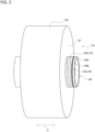
- FIG. 1 is a perspective view of a yarn package 101.
- FIG. 2 is a diagram schematically illustrating the yarn package 101 in a state in which tail connection has been performed.
- FIG. 3 is a perspective view illustrating a thread cutting tool 1 according to an embodiment of the present invention.
- the thread cutting tool 1 is used for cutting a yarn tail 103 of the yarn package 101.
- description below first, description will be made for tail connection work performed on the yarn package 101 for continuously processing a yarn 102 delivered from the yarn package 101 and cutting work of the yarn tail 103 of the yarn package 101 performed prior to the tail connection work. Then, the thread cutting tool 1 according to an embodiment of the present invention used in the cutting work of the yarn tail 103 of the yarn package 101 will be described.
- a textile machine such as a false-twisting machine
- processing is performed on the yarn 102 supplied by being delivered from the yarn package 101.
- the tail connection work is performed for connecting the yarn package 101 from which the yarn 102 is supplied to the textile machine first and the yarn package 101 from which the yarn 102 is supplied to the textile machine next.
- the yarn package 101 from which the yarn 102 is supplied to the textile machine first is also referred to as a yarn package 101a and the yarn package 101 from which the yarn 102 is supplied to the textile machine next is also referred to as a yarn package 101b.
- tail connection work work of tying the yarn tail 103 as the yarn 102 on the inner layer side of the yarn package 101a from which the yarn 102 is supplied to the textile machine first and a thread end 104 on an outer layer side of the yarn package 101b from which the yarn is supplied to the textile machine next is performed.
- the yarn tail 103 of the yarn package 101a and the thread end 104 of the yarn package 101b are tied and a tail connection portion 105 is formed in between the yarn tail 103 of the yarn package 101a and the thread end 104 of the yarn package 101b.
- the yarn 102 is delivered from the outer layer side to the inner layer side in the yarn package 101a.
- the yarn package 101a is delivered to the yarn tail 103 on the inner layer side
- the thread end 104 of the yarn package 101b connected with the yarn package 101a via the tail connection portion 105 is continuously supplied to the textile machine.
- the yarn 102 is delivered from the outer layer side to the inner layer side and supplied to the textile machine.
- the tail connection work is performed also for the yarn package 101b, with the yarn package 101 from which the yarn 102 is supplied to the textile machine next to the yarn package 101b. That is, the tail connection portion 105 is formed in between the yarn tail 103 of the yarn package 101b and the thread end 104 on the outer layer side of the yarn package 101 from which the yarn 102 is supplied to the textile machine next to the yarn package 101b.
- the yarn package 101 on which the tail connection work is performed and the cutting work of the yarn tail 103 of the yarn package 101 performed in prior to the tail connection work will be described.
- the yarn package 101 is formed by winding the yarn 102 around the paper tube 106.
- the paper tube 106 is formed in a cylindrical shape as a tube made of paper, for example.
- the yarn package 101 is formed by winding the yarn 102 in a cylindrical shape around the outer circumference of the paper tube 106.
- the cylindrical paper tube 106 is provided a slit 106a in one end side of a longitudinal direction of the paper tube 106 that is a direction extending in the cylindrical shape.
- the slit 106a is provided as a groove extending in a circumferential direction in an outer circumference of a portion in one end side of a longitudinal direction of the paper tube 106.
- the yarn 102 is wound around the slit 106a in an overlapping manner by several rounds in a circumferential direction of the paper tube 106, so that a bunch winding part 103a is formed.
- the yarn 102 is fixed to the paper tube 106.
- a spiral winding part 103b is formed by spirally winding the yarn 102 continuous to the bunch winding part 103a around the paper tube 106 by several rounds.
- the yarn tail 103 on the inner layer side of the yarn package 101 is provided.
- the yarn tail 103 on the inner layer side of the yarn package 101 includes the bunch winding part 103a and the spiral winding part 103b.
- the yarn 102 is wound around the paper tube 106 while reciprocating in an axial direction X of the paper tube 106, a main winding portion 107 is formed by winding the yarn 102 around the paper tube 106 in a cylindrical shape, and the yarn package 101 is formed.
- the axial direction X of the paper tube 106 is a cylindrical axial direction of the paper tube 106 extending in the cylindrical shape. In FIG. 2 , a direction parallel to the axial direction X is indicated by a double sided arrow X.
- the cutting work of the yarn tail 103 of the yarn package 101 is performed.
- the cutting work of the yarn tail 103 is performed as work of cutting the yarn tail 103 in the spiral winding part 103b.
- the thread cutting tool 1 as described later is used.
- the yarn tail 103 is in a state in which the bunch winding part 103a is cut and removed from the spiral winding part 103b.
- the tail connection work is performed.
- the yarn tail 103 in which the bunch winding part 103a is cut and removed by cutting is tied and connected with the thread end 104 on the outer layer side of another yarn package 101 as a mate of the tail connection.
- the thread cutting tool 1 according to an embodiment of the present invention used in the cutting work of the yarn tail 103 will be described below.
- FIG. 4 is a front view (A) of the thread cutting tool 1 and a rear view (B) of the thread cutting tool 1.
- FIG. 5 is a perspective view of the thread cutting tool 1 with an exploded view of a part thereof.
- FIG. 6 is a diagram illustrating a state in which the thread cutting tool 1 is attached to the paper tube 106 of the yarn package 101.
- FIG. 7 is a diagram illustrating the state in which the thread cutting tool 1 is attached to the paper tube 106 of the yarn package 101 in an enlarged manner and is a diagram illustrating a cross section of the yarn package 101.
- the cross section of the yarn 102 in the yarn tail 103 is indicated as a cross section hatched with solid black. That is, the cross section of the yarn 102 in the bunch winding part 103a and the spiral winding part 103b of the yarn tail 103 is indicated by the cross section hatched with solid black.
- the thread cutting tool 1 is provided as a tool for cutting the yarn tail 103 as the yarn 102 on the inner layer side of the yarn package 101 formed by winding the yarn 102 around the paper tube 106.
- the thread cutting tool 1 is attached to the edge 106b of the paper tube 106 of the yarn package 101.
- the thread cutting tool 1 is operated by a worker in a state in which the thread cutting tool 1 is attached to the edge 106b of the paper tube 106, the yarn tail 103 is cut.
- the edge 106b of the paper tube 106 to which the thread cutting tool 1 is attached is an edge on one end side of the paper tube 106 in an axial direction X and is an end on the end side provided with the yarn tail 103.
- a direction parallel to the axial direction X of the paper tube 106 is indicated by a double sided arrow.
- the thread cutting tool 1 includes a body 11, an operation part 12, a blade part 13, a biasing part 14, a positioning spring member 15, and the like.
- the thread cutting tool 1 is attached to the edge 106b of the paper tube 106 in the body 11.
- the operation part 12 provided rotatably with respect to the body 11 is operated to rotate by the worker.
- the blade part 13 is rotatably coupled to the operation part 12 and is coupled to the operation part 12 by the biasing part 14 provided as a spring member.
- the thread cutting tool 1 is configured such that, when the operation part 12 is operated to rotate, the blade part 13 biased by the operation part 12 via the biasing part 14 cuts the yarn tail 103.
- the configuration of the thread cutting tool 1 will be described below in more details.
- the body 11 is a member to enable the thread cutting tool 1 to be attached to the edge 106b of the paper tube 106 and is provided as a member for supporting the operation part 12 rotatably.
- the body 11 includes a base member 16a and a cover member 16b. The base member 16a and the cover member 16b are coupled with a screw member (not shown) in a state of being combined with each other, the integral body 11 is formed.
- the body 11 includes a hook part 17 and a pressing part 18 and is configured to be attached to the edge 106b of the paper tube 106 by the hook part 17 and the pressing part 18.
- the hook part 17 is provided as a portion hooked on the inside of the edge 106b of the paper tube 106 in the body 11.
- the hook part 17 is provided as a part of a portion forming a shape of an outer edge of the body 11, is formed to have a claw shape, a tabular shape, or a projection shape, and is formed to have a shape projecting in a cantilever shape.
- the hook part 17 is configured such that, when the body 11 is attached to the edge 106b of the paper tube 106, the hook part 17 is inserted to the inside of the edge 106b of the paper tube 106 and engages with the inner circumference of the edge 106b of the paper tube 106 in a radial direction of the paper tube 106, so that the hook part 17 is hooked on the inside of the edge 106b of the paper tube 106.
- the hook part 17 is provided as a part of the base member 16a in the body 11.
- the pressing part 18 of the body 11 is provided as a portion pressing the outside of the edge 106b of the paper tube 106 in the body 11.
- the pressing part 18 is provided as a part of a portion forming the shape of the outer edge of the body 11 and is provided so as to face the hook part 17 via a recess space partitioned by forming a part of the shape of the outer edge of the body 11 so as to be dented to the inside.
- the pressing part 18 facing the hook part 17 is formed to have a shape protruding in a projection shape toward the hook part 17.
- the recess space partitioned by a part of the shape of the outer edge of the body 11 is dented in between the pressing part 18 and the hook part 17, the edge 106b of the paper tube 106 is inserted.
- the pressing part 18 is configured such that, when the body 11 is attached to the edge 106b of the paper tube 106, the pressing part 18 abuts the outer circumference of the edge 106b of the paper tube 106 in a radial direction of the paper tube 106, so that the pressing part 18 presses the outside of the edge 106b of the paper tube 106.
- the pressing part 18 is provided as a part of the base member 16a and a part of the cover member 16b in the body 11.
- the hook part 17 When the body 11 is attached to the edge 106b of the paper tube 106, the hook part 17 is inserted to the inside of the edge 106b of the paper tube 106, and the pressing part 18 is arranged in the outside of the edge 106b of the paper tube 106. As a result, the hook part 17 is hooked on the inside of the edge 106b of the paper tube 106, and the pressing part 18 is in the state of pressing the outside of the edge 106b of the paper tube 106. That is, the state is established in which the hook part 17 and the pressing part 18 sandwich and hold the edge 106b of the paper tube 106 from both sides in a radial direction of the paper tube 106.
- the body 11 is configured such that the hook part 17 and the pressing part 18 sandwich and hold the edge 106b of the paper tube 106 from both sides in a radial direction of the paper tube 106, so that the body 11 is attached to the edge 106b of the paper tube 106.
- the edge 106b of the paper tube 106 When the body 11 is attached to the edge 106b of the paper tube 106, the edge 106b of the paper tube 106 is inserted to the recess space partitioned by a part of the shape of the outer edge of the body 11 being dented in between the pressing part 18 and the hook part 17.
- the body 11 is provided with a abutting surface 19 abutting an end surface of the edge 106b of the paper tube 106 inserted to the recess space, in a depth side of the recess space in between pressing part 18 and the hook part 17 (see FIGS. 3 to 5 and 7 ).
- the hook part 17 is inserted to the inside of the edge 106b of the paper tube 106 up to a position where the edge 106b of the paper tube 106 abuts the abutting surface 19.
- the edge 106b of the paper tube 106 and the abutting surface 19 abut each other, the body 11 in an axial direction X of the paper tube 106 when the body 11 is attached to the edge 106b of the paper tube 106 is positioned.
- the body 11 is provided with a guide part 20 and an abutting part 21 as components for rotatably supporting the operation part 12 as described later.
- the guide part 20 and the abutting part 21 are provided as components enabling a rotation operation of the operation part 12 with respect to the body 11, the operation being specific to an embodiment of the present invention.
- the configurations of the guide part 20 and the abutting part 21 will be described later.
- FIG. 8 is a diagram illustrating the state in which the thread cutting tool 1 is attached to the paper tube 106 of the yarn package 101 in an enlarged manner and is a diagram illustrating a state in which a part of the body 11 of the thread cutting tool 1 is omitted in order to illustrate an internal structure of the thread cutting tool 1.
- FIG. 8 illustrates a state in which the cover member 16b being a part of the body 11 of the thread cutting tool 1 is omitted in order to illustrate the internal structure of the thread cutting tool 1.
- a cross section of the yarn 102 in the yarn tail 103 is indicated by a cross section with hatching with solid black.
- the operation part 12 is swingably coupled to the body 11 and is provided as a member operated to rotate with respect to the body 11.
- the operation part 12 is provided a grip part 22, a rotation operation part 23, a shaft 24, a fulcrum projection part 25, and the like.
- the grip part 22 is provided as a portion operated by the worker gripping the grip part 22 when the operation part 12 is operated to rotate with respect to the body 11.
- the grip part 22 is formed to have an elongated prismatic shape and is provided so as to facilitate manually gripping by the worker.
- the grip 22 rotates along a direction approaching the yarn 102 on the outer layer side of the yarn package 101.
- the grip part 22 rotates along a direction of approaching the yarn 102 on the outer layer side of the yarn package 101 and approaching the main winding portion 107 formed by winding the yarn 102 around the paper tube 106 in a cylindrical shape.
- a rotation operation direction P that is a direction in which the grip part 22 is operated to rotate by the worker is indicated by an arrow P.
- the rotation operation part 23 is provided integrally to the grip part 22 and is provided as a portion that performs rotation operation with respect to the body 11 in the inside of the body 11.
- the rotation operation part 23 is provided integrally with the grip part 22 in one end in a longitudinal direction of the elongated grip part 22.
- the rotation operation part 23 is provided as a portion having a basic shape of a tabular shape or a block shape.
- the rotation operation part 23 is arranged in the inside of the body 11 and is arranged in between the base member 16a and the cover member 16b of the body 11.
- the shaft 24 is provided as a portion that couples the operation part 12 swingably with the body 11, to enable rotation operation of the operation part 12 with respect to the body 11. That is, the operation part 12 is configured such that, since the shaft 24 is provided, the operation part 12 is swingably coupled to the body 11 via the shaft and is operated to rotate with respect to the body 11.
- the shaft 24 is provided integrally with the rotation operation part 23 and is provided so as to project in a cylindrical shape in a circular cross section toward both sides of the rotation operation part 23. That is, the shaft 24 is provided so as to project in a cylindrical shape toward both sides of the base member 16a side and the cover member 16b side of the body 11 from the rotation operation part 23.
- One end of the shaft 24 projecting to the base member 16a side from the rotation operation part 23 is inserted to the guide part 20 provided as a long hole in the base member 16a in a loose-fitting state.
- the other end of the shaft 24 projecting from the rotation operation part 23 to the cover member 16b side is inserted to the guide part 20 provided as a long hole in the cover member 16b in a loose-fitting state. Since both ends of the shaft 24 are inserted to the guide part 20 provided in the base member 16a and the cover member 16b of the body 11, respectively, in a loose-fitting state, the operation part 12 coupled swingably to the body 11.
- the fulcrum projection part 25 is provided as a portion that abuts the abutting part 21 provided in the body 11 when the operation part 12 is operated to rotate with respect to the body 11, to enable rotation operation of the operation part 12 having as a fulcrum an abutting position between the abutting part 21 and the fulcrum projection part 25.
- the fulcrum projection part 25 is provided integrally with the grip part 22 and is provided so as to project in a projection shape from the grip part 22 toward both sides. More specifically, the fulcrum projection part 25 is provided so as to project from the end side coupled integrally with the rotation operation part 23 in the grip part 22, and is provided so as to project both sides of the base member 16a side and the cover member 16b side of the body 11.
- the fulcrum projection part 25 is provided so as to project from the grip part 22 to both sides in the outside of the body 11. That is, the fulcrum projection part 25 projecting from the grip part 22 to the base member 16a side projects to the base member 16a side in the outside of the base member 16a. The fulcrum projection part 25 projecting from the grip part 22 to the cover member 16b side projects to the cover member 16b side in the outside of the cover member 16b.
- the blade part 13 is provided as a yarn cutting member that is coupled rotatably to the operation part 12 via the shaft 24 of the operation part 12 and cuts the yarn tail 103.
- the blade part 13 includes a blade tip 13a extending linearly and is configured to cut the yarn tail 103 with the blade tip 13a.
- the blade part 13 is provided with a through hole 13b.
- the shaft 24 of the operation part 12 penetrates the through hole 13b of the blade part 13, and the shaft 24 of the operation part 12 is inserted rotatably to the through hole 13b.
- the blade part 13 is coupled rotatably to the operation part 12 via the shaft 24.
- One of both ends of the shaft 24 projecting in both sides of the rotation operation part 23 of the operation part 12 penetrates the through hole 13b of the blade part 13.
- the biasing part 14 is provided as a member that couples the blade part 13 and the operation part 12 and biases the blade part 13 along a direction in which the operation part 12 rotates with respect to the body 11 when the operation part 12 rotates with respect to the body 11.
- the biasing part 14 is provided as a sprig member and is provided as a coil spring, for example.
- the biasing part 14 couples the blade part 13 and the operation part 12 in a state of being arranged in the inside of the body 11.
- the end on one end side of the biasing part 14 is attached and fixed to the rotation operation part 23 of the operation part 12.
- the end on the other end side of the biasing part 14 is attached and fixed to the blade part 13.
- the end on one end side of the biasing part 14 and the rotation operation part 23 are fixed, for example, by welding, or fixed by engagement of the projection provided in one of the end on one end side of the biasing part 14 and the rotation operation part 23 and the groove provided in the other of them.
- the end on the other end side of the biasing part 14 and the blade part 13 are fixed, for example, by welding, or fixed by engagement of the projection provided in one of the end on the other end side of the biasing part 14 and the blade part 13 and the groove provided in the other of them.
- the positioning spring member 15 is provided as a spring member arranged so as to bias the operation part 12 against the body 11 along a direction opposite to a direction in which the operation part 12 operated by the worker rotates with respect to the body 11.
- the positioning spring member 15 is provided as a spring member for positioning the operation part 12 with respect to the body 11 in a state before the operation part 12 is operated to rotate in a direction of approaching the yarn 102 in the outer layer side of the yarn package 101 in a state in which the body 11 is attached to the edge 106b of the paper tube 106.
- a rotation operation direction P that is a direction in which the operated operation part 12 rotates with respect to the body 11 is indicated by an arrow P.
- An opposite rotation operation direction Q that is a direction in which the positioning spring member 15 biases the operation part 12 against the body 11 along a direction opposite to the rotation operation direction P is indicated by an arrow Q.
- the positioning spring member 15 provided as a spring member is configured as a coil spring, for example.
- the positioning spring member 15 is provided a compression coil spring.
- the positioning spring member 15 is arranged in the inside of the body 11, and is arranged such that an end on one end side of the positioning spring member 15 abuts the operation part 12 to bias the operation part 12 and an end on the other end side of the positioning spring member 15 abuts the body 11 to bias the body 11. Since the positioning spring member 15 is provided so as to bias the operation part 12 against the body 11, in a state before the rotation operation of the operation part 12 with respect to the body 11 is performed, the position of the operation part 12 with respect to the body 11 is positioned.
- the operation part 12 is provided with a positioning spring holding part 26.
- the positioning spring holding part 26 is provided integrally with the grip part 22 and the rotation operation part 23, arranged in the inside of the body 11, and is provided as a portion that holds the end on the one end side of the positioning spring member 15.
- the positioning spring holding part 26 is provided with a holding hole 26a formed to be dented. The end of one end side of the positioning spring member 15 abuts the positioning spring holding part 26 in a state of being inserted to the holding hole 26a and fitted to the holding hole 26a and is held by the positioning spring holding part 26.
- the positioning spring holding part 26 is provided so as to be able to abut a step part 27 provided in an inner wall of the base member 16a in the body 11, in the inside of the body 11 (see FIGS. 5 and 8 ).
- a step part 27 provided in an inner wall of the base member 16a in the body 11, in the inside of the body 11 (see FIGS. 5 and 8 ).
- the operation part 12 with respect to the body 11 positioned by the positioning spring member 15 biasing the operation part 12 against the body 11 is positioned at a position where the step part 27 of the body 11 and the positioning spring holding part 26 abut each other.
- the body 11 is provided with the positioning spring holding part 28 in the base member 16a.
- the positioning spring holding part 28 is provided as a portion that holds the end on the other end side of the positioning spring member 15.
- the positioning spring holding part 28 is provided with the holding hole 28a formed to be dented. The end on the other end side of the positioning spring member 15 abuts the positioning spring holding part 28 in a state of being inserted to the holding hole 28a and fitted to the holding hole 28a and is held by the positioning spring holding part 28.
- the positioning spring member 15 is provided as a compression coil spring, and is arranged so as to bias the operation part 12 against the body 11 along an opposite rotation operation direction Q that is a direction opposite to a rotation operation direction P in which the operation part 12 is operated to rotate with respect to the body 11, in the inside of the body 11.
- the body 11 is provided with the guide part 20 and the abutting part 21 as components for rotatably supporting the operation part 12.
- the guide parts 20 are provided as long holes to which both ends of the shaft 24 provided in the operation part 12 are respectively inserted.
- the guide parts 20 provided in the body 11 as the long holes are provided as a pair and respectively provided in the base member 16a and the cover member 16b in the body 11.
- illustration of the cover member 16b is omitted and the guide part 20 provided in the cover member 16b is indicated by an alternate long and two short dashes line.
- the guide parts 20 are provided as holes respectively penetrating the base member 16a and the cover member 16b, and are provided as elongated oval long holes, for example.
- One of both ends of the shaft 24 of the operation part 12 penetrates the guide part 20 provided in the base member 16a and inserted to the guide part 20 in a loose-fitting state.
- the other of both ends of the shaft 24 of the operation part 12 penetrates the guide part 20 provided in the cover member 16b and inserted to the guide part 20 in a loose-fitting state.
- Each of both ends of the shaft 24 respectively inserted to the guide parts 20 abuts the edge of the guide part 20 in both end sides in a longitudinal direction of the guide parts as long holes so that a movement amount of the shaft 24 along a longitudinal direction of the guide part 20 is regulated. More specifically, both ends of the shaft 24 respectively inserted to the guide parts respectively abut an edge 20a on one end side and an edge 20b on the other end side in a longitudinal direction of the guide part 20 as the long hole, so that a movement amount of each guide part 20 along a longitudinal direction is regulated (see FIGS. 3 , 4 , and 7 ). Both the edge 20a on one end side and the edge 20b on the other end side of the guide part 20 are formed to have a semi-circular shape.
- the shaft 24 is formed to have a shape extending in a columnar shape in a circular cross section, and is provided so as to be able to abut the edge 20a on one end side and the edge 20b on the other end side of the guide part 20 in the outer circumferential surface of the circular shape. Therefore, the shaft 24 having abutted the edge 20a on one end side or the edge 20b on the other end side of the guide part 20 is in a state of being rotatable in the inside of the guide part 20 while sliding and abutting the edge 20a on one end side and the edge 20b on the other end side of the guide part 20.
- FIGS. 3 , 4 , and 7 illustrates a state in which each of both ends of the shaft 24 abuts the edge 20a on one end side in a longitudinal direction of each guide part 20.
- Each of both ends of the shaft 24 inserted to each guide part 20 is configured to move along a longitudinal direction of the guide part 20 so that the movement of the shaft 24 along a longitudinal direction of the guide part 20 is guided. That is, each of both ends of the shaft 24 inserted to each guide part 20 is configured so as to move while sliding and abutting along the edge of the guide part extending along a longitudinal direction of the guide part 20 as the long hole so that the movement of the guide part 20 along a longitudinal direction is guided.
- the guide part 20 is configured to guide the movement of the shaft 24 and regulate the movement of the shaft 24 with respect to the body 11 by including the above-mentioned configuration.
- the shaft 24 is inserted to the through hole 13b of the blade part 13 and is coupled rotatably to the blade part 13.
- the blade part 13 is coupled to the operation part 12 via the biasing part 14.
- the guide part 20 is configured to guide the movement of the shaft 24 movable together with the blade part 13 with respect to the body 11 and regulate the movement amount of the blade part 13 with respect to the body 11.
- the abutting parts 21 are provided as portions abutting the operation part 12 and serving as a fulcrum of the rotation operation of the operation part 12 with respect to the body 11 when the guide part 20 guides the movement of the shaft 24.
- the abutting parts 21 are provided in the body 11 as a pair, and respectively provided in the base member 16a and the cover member 16b in the body 11.
- the abutting part 21 is provided so as to abut the fulcrum projection part 25 provided in the operation part 12 and serve as a fulcrum of the rotation operation of the operation part 12 with respect to the body 11.
- the abutting part 21 provided in the base member 16a is configured to abut the fulcrum projection part 25 projecting toward the base member 16a side in the operation part 12.
- the abutting part 21 provided in the cover member 16b side is configured to abut the fulcrum projection part 25 projecting toward the cover member 16b side in the operation part 12.
- the abutting part 21 is formed to have a shape projecting toward the outside in each of the base member 16a and the cover member 16b.
- the abutting part 21 projects and extends from each of the base member 16a and the cover member 16b along a direction in which the grip part 22 in the operation part 12 swingably supported by the body 11 projects and extends from the body 11 toward the outside.
- the abutting part 21 is provided to have a shape constricting toward the distal end side projecting and extending from each of the base member 16a and the cover member 16b toward the outside.
- a portion on the distal end side projecting and extending in the abutting part 21 is formed as a curved surface having an arc-shape cross section.
- the abutting part 21 is configured so as to be able to abut the fulcrum projection part 25 of the operation part 12 while smoothly sliding and abutting the fulcrum projection part 25.
- the body 11 is attached to the edge part 106b of the paper tube 106 by holding the state in which the hook part 17 and the pressing part 18 sandwich the edge 106b of the paper tube 106.
- the shaft 24 of the operation part 12 abuts the edge 20a on one end side in a longitudinal direction of the guide part 20 and the movement with respect to the body part 11 is regulated.
- the shaft 24 whose movement with respect to the body 11 is regulated in the edge 20a on one end side of the guide part 20 is rotatable in the inside of the guide part 20 while sliding and abutting the edge 20a on one end side of the guide part 20.
- the blade tip 13a of the blade part 13 rotatably supported by the shaft 24 with respect to the operation part 12 and coupled to the operation part 12 by the biasing part 14 is arranged spaced with a gap from the yarn 102 of the spiral winding part 103b of the yarn tail 103.
- the rotation operation of operating the operation part 12 to rotate with respect to the body 11 is performed.
- the operation part 12 is operated to rotate along a direction of approaching the yarn 102 on the outer layer side of the yarn package 101.
- a first rotation operation and a second rotation operation that are operations performed continuously are performed.
- the first rotation operation and the second rotation operation are continuously performed and performed as one-operation like rotation operation.
- the first rotation operation of operating the operation part 12 to rotate in a direction of approaching the yarn 102 on the outer layer side of the yarn package 101 is performed in a state in which the body 11 is attached to the edge 106b of the paper tube 106. That is, the grip part 22 of the operation part 12 is operated along a rotation operation direction P and the first rotation operation of operating the operation part 12 to rotate along a direction approaching the main winding portion 107 of the yarn package 101 is performed.
- FIG. 9 is a diagram illustrating the state in which the first rotation operation is performed in the thread cutting tool 1 in an enlarged manner and in which a part of the body 11 of the thread cutting tool 1 is omitted in order to indicate the internal structure of the thread cutting tool 1.
- the operation part 12 rotates with respect to the body 11 around the shaft 24 whose movement is regulated by the edge 20a on one end side of the guide part 20.
- the operation part 12 rotates with respect to the body 11 around the shaft 24 by the first rotation operation, the blade tip 13a of the blade part 13 biased toward the edge 106b of the paper tube 106 by the operation part 12 via the biasing part 14 abuts the spiral winding part 103b of the yarn tail 103.
- the operation part 12 abuts the body 11 in the abutting part 21. More specifically, the fulcrum projection part 25 of the operation part 12 abuts the abutting part 21 of the body 11.
- the thread cutting tool 1 is configured such that, by the first rotation operation, the operation part 12 rotates with respect to the body 11 around the shaft 24 whose movement is regulated by the guide part 20, and the blade part 13 biased toward the edge 106b of the paper tube 106 by the operation part 12 via the biasing part 14 abuts the yarn tail 103, and the operation part 12 abuts the body 11 in the abutting part 21.
- the second rotation operation is performed.
- the rotation operation is performed in a direction in which the operation part 12 approaches the yarn 102 on the outer layer side of the yarn package 101 in a state in which the body 11 is attached to the edge 106b of the paper tube 106
- the first rotation operation is performed, the operation part 12 rotates around the shaft 24, the blade part 13 is biased, the blade part 13 abuts the yarn tail 103, and the operation part 12 abuts the body 11 in the abutting part 21.
- the second rotation operation of operating the operation part 12 to further rotate in the direction of approaching the yarn 102 on the outer layer side of the yarn package 101 in a state in which the operation part 12 abuts the body 11 in the abutting part 21 is performed. That is, the second rotation operation of further operating the grip part 22 of the operation part 12 along a rotation operation direction P and operating the operation part 12 to further rotate along a direction of approaching the main winding portion 107 of the yarn package 101.
- FIG. 10 is a diagram illustrating the state in which the second rotation operation is performed in the thread cutting tool 1 in an enlarged manner, and is a diagram illustrating a state in which a part of the body 11 of the thread cutting tool 1 is omitted in order to illustrate an internal structure of the thread cutting tool 1.
- the operation part 12 rotates with the abutting part 21 as a fulcrum.
- the operation part 12 abuts the abutting part 21 of the body 11 in the fulcrum projection part 25, and when the second rotation operation is performed in this state, the operation part 12 rotates with respect to the body 11 with the abutting part 21 of the body 11 that the fulcrum projection part 25 abuts as a fulcrum.
- the shaft 24 movable together with the blade part 13 biased along the rotation operation part P (a direction in which the operation part 12 rotates with respect to the body 11) by the operation part 12 via the biasing part 14 is guided by the guide part 20 and moves. That is, when the operation part 12 rotates with the abutting part 21 as a fulcrum by the second rotation operation, the shaft 24 movable together with the biased blade part 13 is guided by the guide part 20 and moves from the edge 20a side on one end side of the guide part 20 toward the edge 20b side on the other end side along a longitudinal direction of the guide part 20 as the long hole.
- the operation part 12 rotates with the abutting part 21 as a fulcrum by the second rotation operation and the shaft 24 movable together with the blade part 13 is guided by the guide part 20 and moves, so that the blade part 13 slides and moves so as to be spaced from the yarn 102 on the outer layer side of the yarn package 101 along an axial direction X of the paper tube 106.
- the blade tip 13a of the blade part 13 passes the yarn 102 of the spiral winding part 103b of the yarn tail 103.
- the blade tip 13a of the blade part 13 cuts the yarn 102 of the yarn tail 103.
- the end surface of the yarn 102 of the spiral winding part 103b of the yarn tail 103 that has been cut is indicated by a circular end surface indicating only the contour of the yarn 102 without hatching with solid black.
- the cutting work of the yarn tail 103 using the thread cutting tool 1 will be described.
- the cutting work of the yarn tail 103 with respect to the yarn package 101 in a state before the tail connection work is performed as shown in FIG. 2 .
- the thread cutting tool 1 is attached to the edge 106b of the paper tube 106.
- FIG. 11 is a diagram illustrating the state of blade part 13 of the thread cutting tool 1 and the yarn tail 103 of the yarn package 101 when the thread cutting tool 1 cuts the yarn tail 103.
- FIG. 11 is a diagram (A) schematically illustrating the state of the blade part 13 and the yarn tail 103 when the thread cutting tool 1 is attached to the paper tube 106 of the yarn package 101.
- FIG. 11 is another diagram (B) schematically illustrating the state of the blade part 13 and the yarn tail 103 when the first rotation operation is performed.
- FIG. 11 is still another diagram (C) schematically illustrating the state of the blade part 13 and the yarn tail 103 when the second rotation operation is performed.
- the operation part 12 with respect to the body 11 in the state before the first rotation operation is performed is positioned by the positioning spring member 15 (see FIG. 8 ).
- movement of the shaft 24 is regulated in the edge 20a on one end side of the guide part 20, and the blade part 13 is spaced from the yarn tail 103.
- the first rotation operation is performed.
- the operation part 12 rotates around the shaft 24, and the blade 13 biased by the operation part 12 via the biasing part 14 also rotates around the shaft 24 along a rotation direction R indicated by a dashed line arrow R in (A) of FIG. 11 .
- the second rotation operation is performed continuously.
- the operation part 12 rotates with respect to the body 11 with the abutting part 21 as a fulcrum
- the shaft 24 is guided by the guide part 20 and moves together with the blade part 13 biased by the operation part 12 via the biasing part 14.
- the blade part 13 slides and moves so as to be spaced from the yarn 102 on the outer layer side of the yarn package 101 along an axial direction X of the paper tube 106 (see FIGS. 9 and 10 ).
- a slide movement direction S in which the blade part 13 slides and moves is indicated by a dashed line arrow S.
- the operation part 12 is operated to rotate in a direction opposite to the direction of the second rotation operation and the first rotation operation.
- the state of the operation part 12 with respect to the body 11 returns to the same state as that before the first rotation operation is performed. In this state, the body 11 is detached from the edge 106b of the paper tube 106. Thereby, the cutting work of the yarn tail 103 ends.
- the tail connection work is to be performed.
- the thread cutting tool 1 since the body 11 is attached to the edge 106b of the paper tube 106 by the hook part 17 and the pressing part 18, at the time of cutting work of the yarn tail 103, the thread cutting tool 1 can be mechanistically positioned at a predetermined position with respect to the edge 106b of the paper tube 106.
- the blade part 13 abuts the yarn tail 103 at a predetermined position in the edge 106b of the paper tube 106, and subsequently, the second rotation operation is performed, so that the blade part 13 slides and moves to cut the yarn tail 103.
- the yarn tail 103 can be cut at a position where the length of the yarn tail 103 required for the tail connection work is appropriately secured irrespectively of the ability of the worker, and furthermore, the yarn tail 103 can be cut without damaging a portion other than the end to be cut. Since the blade part 13 abuts the yarn tail 103 by the first rotation operation and slides and moves by the second rotation operation to cut the yarn 102, a large damage on the paper tube 106 can also be prevented. Therefore, according to the thread cutting tool 1 of an embodiment of the present invention, in the cutting work of the yarn tail 103, the cutting work can be performed irrespectively of the ability of the worker and a burden on the worker can be reduced.
- the biasing part 14 is a spring member, in the first rotation operation, when the blade part 13 is biased to the operation part 12 via the biasing part 14 and abuts the yarn tail 103, the biasing force transmitted from the operation part 12 to the blade part 13 can be elastically deformed and absorbed by the biasing part 14. Therefore, the blade part 13 is prevented from being excessively pressed against the edge 106 of the paper tube 106 and a large damage on the paper tube 106 can be further prevented.
- the thread cutting tool 1 of an embodiment of the present invention with a simple configuration in which the body 11 is provided with a long hole, it is possible to achieve the guide part 20 that guides the movement of the shaft 24 movable together with the blade part 13 with respect to the body 11 with respect to the body 11 and regulates the movement amount of the blade part 13 with respect to the body 11.
- the operation part 12 with respect to the body 11 in the state before the first rotation operation is performed can be positioned easily by the positioning spring member 15.
Landscapes
- Engineering & Computer Science (AREA)
- Mechanical Engineering (AREA)
- Life Sciences & Earth Sciences (AREA)
- Forests & Forestry (AREA)
- Textile Engineering (AREA)
- Knives (AREA)
- Coiling Of Filamentary Materials In General (AREA)
- Treatment Of Fiber Materials (AREA)
Abstract
Description
- The present invention relates to a thread cutting tool for cutting a yarn tail as a yarn on an inner layer side of a yarn package formed by winding a yarn around a paper tube.
- In a textile machine such as a false-twisting machine, processing is performed on a yarn supplied by being delivered from a yarn package formed by winding a yarn around a paper tube. In such a textile machine, the yarn is continuously processed. Therefore, tail connection work is performed for tying and connecting a yarn tail as a yarn on an inner layer side of a yarn package from which the yarn is supplied to the textile machine first and a thread end on an outer layer side of a yarn package from which the yarn is supplied to the textile machine next.
- The yarn tail on the inner layer side of the yarn package is provided for facilitating the tail connection work. At the time of forming the yarn package, first, a bunch winding part is formed by winding the yarn so as to overlap a slit provided on one end side of a longitudinal direction of the paper tube, so that the yarn is fixed to the paper tube. After the bunch winding part is formed, the yarn is wound spirally around the paper tube by several rounds. By forming the bunch winding part and a portion spirally wound by several rounds as described above, the yarn tail on the inner layer side of the yarn package is provided. When the yarn tail is provided, the yarn is wound around the paper tube while reciprocating in an axial direction of the paper tube, a main winding portion obtained by winding the yarn around the paper tube in a cylindrical shape is formed, and the yarn package is formed.
- When the tail connection work is performed, first, the yarn tail is cut, and the bunch winding part is cut and removed from the yarn tail. The yarn tail from which the bunch winding part is cut and removed by cutting is tied and connected with a thread end on an outer layer side of another yarn package as a mate of the tail connection. As the cutting method of the yarn tail at the time of tail connection work, for example,
Patent Document 1 discloses a method of cutting a yarn tail by a worker operating scissors or a cutter. - Patent Document 1:
Japanese Patent Application Publication No. 2001-72339 - In cutting of the yarn tail, it is necessary to cut the yarn tail at a position where a length of the yarn tail required for the tail connection work is appropriately secured. When a damage is generated in a portion other than the cut end in the cut yarn tail, the quality of the connection portion of the yarn is degraded when the tail connection is performed. As a result, it is also necessary to cut the yarn tail without damaging the yarn tail. The paper tube may be reused and if a large damage is generated in the paper tube at the time of cutting the yarn tail, when the yarn is wound around the paper tube for reuse, the yarn is hooked in the damaged portion generated in the paper tube, which damages the yarn. Therefore, at the time of cutting the yarn tail, it is necessary to perform work with great care so as to prevent the damage on the paper tube. However, according to the method disclosed in
Patent Document 1, since the worker cuts the yarn tail by operating scissors or a cutter, the cutting work of the yarn tail depends on the ability of the worker, which increases a burden on the worker. - The present invention has been made in view of the above-described technical problems, and an objective thereof is to provide a thread cutting tool enabling the cutting work to be performed irrespectively of ability of a worker and capable of reducing a burden on the worker in the cutting work of the yarn tail.
- A first aspect of the present invention is a thread cutting tool for cutting a yarn tail as a yarn on an inner layer side of a yarn package formed by winding a yarn around a paper tube, the thread cutting tool comprising:
- a body including a hook part for being hooked on an inside of an edge of the paper tube and a pressing part for pressing an outside of the edge of the paper tube so that the body can be attached to the edge of the paper tube with the hook part and the pressing part;
- an operation part swingably coupled to the body via a shaft thereof capable of being operated so as to rotate with respect to the body;
- a blade part rotatably coupled to the operation part via the shaft for cutting the yarn tail; and
- a biasing part coupling the blade part and the operation part configured to bias the blade part along a direction of the operation part rotating with respect to the body when the operation part is caused to rotate with respect to the body,
- wherein the body includes a guide part and an abutting part, the guide part inserted with each end of the shaft, the guide part configured to guide movement of the shaft with respect to the body, the shaft movable together with the blade part with respect to the body, the guide part configured to regulate a movement amount of the blade part with respect to the body, the abutting part serving as a fulcrum of rotation operation of the operation part with respect to the body as a result of abutting the operation part when the guide part guides movement of the shaft,
- as a result of a first rotation operation of causing the operation part to rotate in a direction of approaching a yarn on an outer layer side of the yarn package in a state where the body is attached to the edge of the paper tube with the hook part and the pressing part, the operation part rotates with respect to the body around the shaft regulated by the guide part for movement so that the blade part biased toward the edge of the paper tube by the operation part via the biasing part abuts the yarn tail and the operation part abuts the body with the abutting part, and
- as a result of a second rotation operation of further causing the operation part to rotate in a direction of approaching a yarn on an outer layer side in a state where the operation part abuts the body with the abutting part, the operation part rotates with the abutting part as a fulcrum, and the shaft movable together with the blade part biased by the operation part via the biasing part along a direction of the operation part rotating with respect to the body is guided by the guide part to move so that the blade part slides and moves to be spaced from a yarn on an outer layer side along an axial direction of the paper tube, and thereby, the yarn tail is cut by the blade part.
- According to the above-described first aspect of the thread cutting tool, since the body is attached to the edge of the paper tube by the hook part and the pressing part, the thread cutting tool can be mechanistically positioned at a predetermined position with respect to the edge of the paper tube at the time of cutting work of the yarn tail. As a result of the first rotation operation, the blade part abuts the yarn tail at a predetermined position in the edge of the paper tube, and then, as a result of the second rotation operation, the blade part slides and moves to cut the yarn tail. Therefore, the yarn tail can be cut at a position where the length of the yarn tail required for the tail connection work is appropriately secured, irrespectively of the ability of the worker, and further, the yarn tail can also be cut without damaging a portion other than the end to be cut. Since the blade part abuts the yarn tail by the first rotation operation and slides and moves to cut the yarn by the second rotation operation, it is also possible to prevent a large damage on the paper tube. Therefore, according to the above-described first aspect of the thread cutting tool, in the cutting work of the yarn tail, the cutting work can be performed irrespectively of the ability of the worker, and a burden on the worker can be reduced.
- A second aspect of the present invention is the thread cutting tool,
wherein the biasing part is a spring member. - According to the above-described second aspect of the thread cutting tool, since the biasing part is the spring member, at the time of the first rotation operation, when the blade part is biased to the operation part via the biasing part to abut the yarn tail, a biasing force transmitted from the operation part to the blade part can be absorbed by the biasing part elastically deforming. Therefore, it is possible to prevent the blade part from being excessively pressed against the edge of the paper tube and further prevent a large damage on the paper tube.
- A third aspect of the present invention is the thread cutting tool,
wherein the guide part is a long hole provided in the body. - According to the above-described third aspect of the thread cutting tool, with a simple configuration including the long hole in the body, it is possible to achieve the guide part configured to guide movement, with respect to the body, of the shaft movable together with the blade part with respect to the body, and regulate a movement amount of the blade part with respect to the body.
- A fourth aspect of the present invention is the thread cutting tool, further comprising:
a positioning spring member provided as a spring member arranged so as to bias the operation part to the body along a direction opposite to a direction of the operation part having been operated rotating with respect to the body for positioning the operation part with respect to the body in a state before the first rotation operation is performed. - According to the above-described fourth aspect of thread cutting tool, the operation part with respect to the body in a state before the first rotation operation is performed can be positioned easily by the spring member.
- The thread cutting tool according to the present invention does not necessarily include all components in the above-described first to fourth aspects. For example, all components in the above-described second to fourth aspects are not necessary for the thread cutting tool in the above-described first aspect. A configuration in the above-described first aspect and a configuration in any one of the above-described second to fourth aspects may be combined, to such an extent that consistency can be achieved, as a thread cutting tool according to the present invention.
- According to the present invention, it is possible to provide a thread cutting tool enabling cutting work to be performed irrespectively of ability of a worker and capable of reducing a burden on the worker in the cutting work of a yarn tail.
-
-
FIG. 1 is a diagram schematically illustrating a yarn package in a state in which tail connection has been performed. -
FIG. 2 is a perspective view of the yarn package. -
FIG. 3 is a perspective view illustrating a thread cutting tool according to an embodiment of the present invention. -
FIG. 4 is a front view (A) of the thread cutting tool and a rear view (B) of the thread cutting tool. -
FIG. 5 is a perspective view of the thread cutting tool with an exploded view of a part thereof. -
FIG. 6 is a diagram illustrating a state in which the thread cutting tool is attached to a paper tube of the yarn package. -
FIG. 7 is a diagram illustrating the state in which the thread cutting tool is attached to the paper tube of the yarn package in an enlarged manner and is a diagram illustrating the cross section of the yarn package. -
FIG. 8 is a diagram illustrating the state in which the thread cutting tool is attached to the paper tube of the yarn package in an enlarged manner and is a diagram illustrating a state in which a part of the body of the thread cutting tool is omitted in order to illustrate an internal structure of the thread cutting tool. -
FIG. 9 is a diagram illustrating a state in which a first rotation operation has been performed in the thread cutting tool in an enlarged manner and is a diagram illustrating a state in which a part of the body of the thread cutting tool is omitted in order to illustrate the internal structure of the thread cutting tool. -
FIG. 10 is a diagram illustrating a state in which a second rotation operation has been performed in the thread cutting tool in an enlarged manner and is a diagram in which a part of the body of the thread cutting tool is omitted in order to illustrate the internal structure of the thread cutting tool. -
FIG. 11 is a diagram illustrating a state of a blade part of the thread cutting tool and a yarn tail of the yarn package when the thread cutting tool cuts the yarn tail, (A) is a diagram illustrating a state of the blade part and the yarn tail when the thread cutting tool is attached to the paper tube of the yarn package, (B) is a diagram illustrating the state of the blade part and the yarn tail when the first rotation operation has been performed, and (C) is a diagram illustrating the state of the blade part and the yarn tail when the second rotation operation has been performed. - Hereinafter, embodiments for implementing the present invention will be described with reference to the drawings. The present invention is widely applicable to various uses as a thread cutting tool for cutting a yarn tail as a yarn on an inner layer side of a yarn package formed by winding a yarn around the paper tube.
-
FIG. 1 is a perspective view of ayarn package 101.FIG. 2 is a diagram schematically illustrating theyarn package 101 in a state in which tail connection has been performed.FIG. 3 is a perspective view illustrating athread cutting tool 1 according to an embodiment of the present invention. Thethread cutting tool 1 is used for cutting ayarn tail 103 of theyarn package 101. In the description below, first, description will be made for tail connection work performed on theyarn package 101 for continuously processing ayarn 102 delivered from theyarn package 101 and cutting work of theyarn tail 103 of theyarn package 101 performed prior to the tail connection work. Then, thethread cutting tool 1 according to an embodiment of the present invention used in the cutting work of theyarn tail 103 of theyarn package 101 will be described. - With reference to
FIG. 1 , in a textile machine (not shown) such as a false-twisting machine, processing is performed on theyarn 102 supplied by being delivered from theyarn package 101. In the textile machine, since theyarn 102 is continuously processed, the tail connection work is performed for connecting theyarn package 101 from which theyarn 102 is supplied to the textile machine first and theyarn package 101 from which theyarn 102 is supplied to the textile machine next. For convenience of the description, as shown inFIG. 1 , theyarn package 101 from which theyarn 102 is supplied to the textile machine first is also referred to as ayarn package 101a and theyarn package 101 from which theyarn 102 is supplied to the textile machine next is also referred to as ayarn package 101b. - As the tail connection work, work of tying the
yarn tail 103 as theyarn 102 on the inner layer side of theyarn package 101a from which theyarn 102 is supplied to the textile machine first and athread end 104 on an outer layer side of theyarn package 101b from which the yarn is supplied to the textile machine next is performed. As a result of the tail connection work, theyarn tail 103 of theyarn package 101a and thethread end 104 of theyarn package 101b are tied and atail connection portion 105 is formed in between theyarn tail 103 of theyarn package 101a and thethread end 104 of theyarn package 101b. - During the processing on the
yarn 102 of theyarn package 101a, theyarn 102 is delivered from the outer layer side to the inner layer side in theyarn package 101a. When theyarn package 101a is delivered to theyarn tail 103 on the inner layer side, thethread end 104 of theyarn package 101b connected with theyarn package 101a via thetail connection portion 105 is continuously supplied to the textile machine. Then, also in theyarn package 101b, theyarn 102 is delivered from the outer layer side to the inner layer side and supplied to the textile machine. The tail connection work is performed also for theyarn package 101b, with theyarn package 101 from which theyarn 102 is supplied to the textile machine next to theyarn package 101b. That is, thetail connection portion 105 is formed in between theyarn tail 103 of theyarn package 101b and thethread end 104 on the outer layer side of theyarn package 101 from which theyarn 102 is supplied to the textile machine next to theyarn package 101b. - Next, the
yarn package 101 on which the tail connection work is performed and the cutting work of theyarn tail 103 of theyarn package 101 performed in prior to the tail connection work will be described. With reference toFIG. 2 , theyarn package 101 is formed by winding theyarn 102 around thepaper tube 106. Thepaper tube 106 is formed in a cylindrical shape as a tube made of paper, for example. Theyarn package 101 is formed by winding theyarn 102 in a cylindrical shape around the outer circumference of thepaper tube 106. - The
cylindrical paper tube 106 is provided aslit 106a in one end side of a longitudinal direction of thepaper tube 106 that is a direction extending in the cylindrical shape. Theslit 106a is provided as a groove extending in a circumferential direction in an outer circumference of a portion in one end side of a longitudinal direction of thepaper tube 106. At the time of forming theyarn package 101, first, theyarn 102 is wound around theslit 106a in an overlapping manner by several rounds in a circumferential direction of thepaper tube 106, so that abunch winding part 103a is formed. As a result of thebunch winding part 103a formed, theyarn 102 is fixed to thepaper tube 106. - After the
bunch winding part 103a is formed, aspiral winding part 103b is formed by spirally winding theyarn 102 continuous to thebunch winding part 103a around thepaper tube 106 by several rounds. As a result of formation of thebunch winding part 103a formed by winding around theslit 106a in an overlapping manner and thespiral winding part 103b formed by spirally winding around thepaper tube 106 continuously to thebunch winding part 103a, by several rounds, theyarn tail 103 on the inner layer side of theyarn package 101 is provided. In a state before the cutting work of theyarn tail 103 performed in prior to the tail connection work is performed, theyarn tail 103 on the inner layer side of theyarn package 101 includes thebunch winding part 103a and thespiral winding part 103b. When theyarn tail 103 is provided, theyarn 102 is wound around thepaper tube 106 while reciprocating in an axial direction X of thepaper tube 106, a main windingportion 107 is formed by winding theyarn 102 around thepaper tube 106 in a cylindrical shape, and theyarn package 101 is formed. The axial direction X of thepaper tube 106 is a cylindrical axial direction of thepaper tube 106 extending in the cylindrical shape. InFIG. 2 , a direction parallel to the axial direction X is indicated by a double sided arrow X. - When the tail connection work is performed, in prior to the tail connection work, the cutting work of the
yarn tail 103 of theyarn package 101 is performed. The cutting work of theyarn tail 103 is performed as work of cutting theyarn tail 103 in thespiral winding part 103b. In the cutting work of theyarn tail 103, thethread cutting tool 1 as described later is used. As a result of the cutting work of theyarn tail 103, theyarn tail 103 is in a state in which thebunch winding part 103a is cut and removed from thespiral winding part 103b. After the cutting work of theyarn tail 103, the tail connection work is performed. As a result of the tail connection work, theyarn tail 103 in which thebunch winding part 103a is cut and removed by cutting is tied and connected with thethread end 104 on the outer layer side of anotheryarn package 101 as a mate of the tail connection. Thethread cutting tool 1 according to an embodiment of the present invention used in the cutting work of theyarn tail 103 will be described below. -
FIG. 4 is a front view (A) of thethread cutting tool 1 and a rear view (B) of thethread cutting tool 1.FIG. 5 is a perspective view of thethread cutting tool 1 with an exploded view of a part thereof.FIG. 6 is a diagram illustrating a state in which thethread cutting tool 1 is attached to thepaper tube 106 of theyarn package 101.FIG. 7 is a diagram illustrating the state in which thethread cutting tool 1 is attached to thepaper tube 106 of theyarn package 101 in an enlarged manner and is a diagram illustrating a cross section of theyarn package 101. InFIG. 7 , the cross section of theyarn 102 in theyarn tail 103 is indicated as a cross section hatched with solid black. That is, the cross section of theyarn 102 in thebunch winding part 103a and thespiral winding part 103b of theyarn tail 103 is indicated by the cross section hatched with solid black. - With reference to
FIGS. 2 to 7 , thethread cutting tool 1 according to an embodiment of the present invention is provided as a tool for cutting theyarn tail 103 as theyarn 102 on the inner layer side of theyarn package 101 formed by winding theyarn 102 around thepaper tube 106. At the time of the cutting work of theyarn tail 103, thethread cutting tool 1 is attached to theedge 106b of thepaper tube 106 of theyarn package 101. When thethread cutting tool 1 is operated by a worker in a state in which thethread cutting tool 1 is attached to theedge 106b of thepaper tube 106, theyarn tail 103 is cut. Theedge 106b of thepaper tube 106 to which thethread cutting tool 1 is attached is an edge on one end side of thepaper tube 106 in an axial direction X and is an end on the end side provided with theyarn tail 103. InFIGS. 6 and7 , a direction parallel to the axial direction X of thepaper tube 106 is indicated by a double sided arrow. - The
thread cutting tool 1 includes abody 11, anoperation part 12, ablade part 13, a biasingpart 14, apositioning spring member 15, and the like. Thethread cutting tool 1 is attached to theedge 106b of thepaper tube 106 in thebody 11. In a state in which thethread cutting tool 1 is attached to thepaper tube 106, theoperation part 12 provided rotatably with respect to thebody 11 is operated to rotate by the worker. Theblade part 13 is rotatably coupled to theoperation part 12 and is coupled to theoperation part 12 by the biasingpart 14 provided as a spring member. Thethread cutting tool 1 is configured such that, when theoperation part 12 is operated to rotate, theblade part 13 biased by theoperation part 12 via the biasingpart 14 cuts theyarn tail 103. The configuration of thethread cutting tool 1 will be described below in more details. - With reference to
FIG. 3 to 7 , thebody 11 is a member to enable thethread cutting tool 1 to be attached to theedge 106b of thepaper tube 106 and is provided as a member for supporting theoperation part 12 rotatably. In an embodiment of the present invention, thebody 11 includes abase member 16a and acover member 16b. Thebase member 16a and thecover member 16b are coupled with a screw member (not shown) in a state of being combined with each other, theintegral body 11 is formed. - With reference to
FIGS. 3 to 7 , thebody 11 includes ahook part 17 and apressing part 18 and is configured to be attached to theedge 106b of thepaper tube 106 by thehook part 17 and thepressing part 18. Thehook part 17 is provided as a portion hooked on the inside of theedge 106b of thepaper tube 106 in thebody 11. Thehook part 17 is provided as a part of a portion forming a shape of an outer edge of thebody 11, is formed to have a claw shape, a tabular shape, or a projection shape, and is formed to have a shape projecting in a cantilever shape. Thehook part 17 is configured such that, when thebody 11 is attached to theedge 106b of thepaper tube 106, thehook part 17 is inserted to the inside of theedge 106b of thepaper tube 106 and engages with the inner circumference of theedge 106b of thepaper tube 106 in a radial direction of thepaper tube 106, so that thehook part 17 is hooked on the inside of theedge 106b of thepaper tube 106. In an embodiment of the present invention, thehook part 17 is provided as a part of thebase member 16a in thebody 11. - The
pressing part 18 of thebody 11 is provided as a portion pressing the outside of theedge 106b of thepaper tube 106 in thebody 11. Thepressing part 18 is provided as a part of a portion forming the shape of the outer edge of thebody 11 and is provided so as to face thehook part 17 via a recess space partitioned by forming a part of the shape of the outer edge of thebody 11 so as to be dented to the inside. Thepressing part 18 facing thehook part 17 is formed to have a shape protruding in a projection shape toward thehook part 17. The recess space partitioned by a part of the shape of the outer edge of thebody 11 is dented in between thepressing part 18 and thehook part 17, theedge 106b of thepaper tube 106 is inserted. Thepressing part 18 is configured such that, when thebody 11 is attached to theedge 106b of thepaper tube 106, thepressing part 18 abuts the outer circumference of theedge 106b of thepaper tube 106 in a radial direction of thepaper tube 106, so that thepressing part 18 presses the outside of theedge 106b of thepaper tube 106. In an embodiment of the present invention, thepressing part 18 is provided as a part of thebase member 16a and a part of thecover member 16b in thebody 11. - When the
body 11 is attached to theedge 106b of thepaper tube 106, thehook part 17 is inserted to the inside of theedge 106b of thepaper tube 106, and thepressing part 18 is arranged in the outside of theedge 106b of thepaper tube 106. As a result, thehook part 17 is hooked on the inside of theedge 106b of thepaper tube 106, and thepressing part 18 is in the state of pressing the outside of theedge 106b of thepaper tube 106. That is, the state is established in which thehook part 17 and thepressing part 18 sandwich and hold theedge 106b of thepaper tube 106 from both sides in a radial direction of thepaper tube 106. As described above, thebody 11 is configured such that thehook part 17 and thepressing part 18 sandwich and hold theedge 106b of thepaper tube 106 from both sides in a radial direction of thepaper tube 106, so that thebody 11 is attached to theedge 106b of thepaper tube 106. - When the
body 11 is attached to theedge 106b of thepaper tube 106, theedge 106b of thepaper tube 106 is inserted to the recess space partitioned by a part of the shape of the outer edge of thebody 11 being dented in between thepressing part 18 and thehook part 17. Thebody 11 is provided with a abuttingsurface 19 abutting an end surface of theedge 106b of thepaper tube 106 inserted to the recess space, in a depth side of the recess space in between pressingpart 18 and the hook part 17 (seeFIGS. 3 to 5 and7 ). When thebody 11 is attached to theedge 106b of thepaper tube 106, thehook part 17 is inserted to the inside of theedge 106b of thepaper tube 106 up to a position where theedge 106b of thepaper tube 106 abuts the abuttingsurface 19. When theedge 106b of thepaper tube 106 and the abuttingsurface 19 abut each other, thebody 11 in an axial direction X of thepaper tube 106 when thebody 11 is attached to theedge 106b of thepaper tube 106 is positioned. - With reference to
FIGS. 3 to 5 and7 , thebody 11 is provided with aguide part 20 and anabutting part 21 as components for rotatably supporting theoperation part 12 as described later. Theguide part 20 and theabutting part 21 are provided as components enabling a rotation operation of theoperation part 12 with respect to thebody 11, the operation being specific to an embodiment of the present invention. The configurations of theguide part 20 and theabutting part 21 will be described later. -
FIG. 8 is a diagram illustrating the state in which thethread cutting tool 1 is attached to thepaper tube 106 of theyarn package 101 in an enlarged manner and is a diagram illustrating a state in which a part of thebody 11 of thethread cutting tool 1 is omitted in order to illustrate an internal structure of thethread cutting tool 1.FIG. 8 illustrates a state in which thecover member 16b being a part of thebody 11 of thethread cutting tool 1 is omitted in order to illustrate the internal structure of thethread cutting tool 1. InFIG. 8 , a cross section of theyarn 102 in theyarn tail 103 is indicated by a cross section with hatching with solid black. With reference toFIGS. 3 to 8 , theoperation part 12 is swingably coupled to thebody 11 and is provided as a member operated to rotate with respect to thebody 11. Theoperation part 12 is provided agrip part 22, arotation operation part 23, ashaft 24, afulcrum projection part 25, and the like. - With reference to
FIGS. 3 to 8 , thegrip part 22 is provided as a portion operated by the worker gripping thegrip part 22 when theoperation part 12 is operated to rotate with respect to thebody 11. Thegrip part 22 is formed to have an elongated prismatic shape and is provided so as to facilitate manually gripping by the worker. When theoperation part 12 is operated to rotate with respect to thebody 11 by the worker, thegrip 22 rotates along a direction approaching theyarn 102 on the outer layer side of theyarn package 101. In other words, when theoperation part 12 is operated to rotate, thegrip part 22 rotates along a direction of approaching theyarn 102 on the outer layer side of theyarn package 101 and approaching the main windingportion 107 formed by winding theyarn 102 around thepaper tube 106 in a cylindrical shape. InFIGS. 7 and8 , a rotation operation direction P that is a direction in which thegrip part 22 is operated to rotate by the worker is indicated by an arrow P. - With reference to
FIGS. 3 to 5 ,7 , and8 , therotation operation part 23 is provided integrally to thegrip part 22 and is provided as a portion that performs rotation operation with respect to thebody 11 in the inside of thebody 11. Therotation operation part 23 is provided integrally with thegrip part 22 in one end in a longitudinal direction of theelongated grip part 22. For example, therotation operation part 23 is provided as a portion having a basic shape of a tabular shape or a block shape. Therotation operation part 23 is arranged in the inside of thebody 11 and is arranged in between thebase member 16a and thecover member 16b of thebody 11. - With reference
FIGS. 3 to 8 , theshaft 24 is provided as a portion that couples theoperation part 12 swingably with thebody 11, to enable rotation operation of theoperation part 12 with respect to thebody 11. That is, theoperation part 12 is configured such that, since theshaft 24 is provided, theoperation part 12 is swingably coupled to thebody 11 via the shaft and is operated to rotate with respect to thebody 11. Theshaft 24 is provided integrally with therotation operation part 23 and is provided so as to project in a cylindrical shape in a circular cross section toward both sides of therotation operation part 23. That is, theshaft 24 is provided so as to project in a cylindrical shape toward both sides of thebase member 16a side and thecover member 16b side of thebody 11 from therotation operation part 23. One end of theshaft 24 projecting to thebase member 16a side from therotation operation part 23 is inserted to theguide part 20 provided as a long hole in thebase member 16a in a loose-fitting state. The other end of theshaft 24 projecting from therotation operation part 23 to thecover member 16b side is inserted to theguide part 20 provided as a long hole in thecover member 16b in a loose-fitting state. Since both ends of theshaft 24 are inserted to theguide part 20 provided in thebase member 16a and thecover member 16b of thebody 11, respectively, in a loose-fitting state, theoperation part 12 coupled swingably to thebody 11. - The
fulcrum projection part 25 is provided as a portion that abuts theabutting part 21 provided in thebody 11 when theoperation part 12 is operated to rotate with respect to thebody 11, to enable rotation operation of theoperation part 12 having as a fulcrum an abutting position between theabutting part 21 and thefulcrum projection part 25. Thefulcrum projection part 25 is provided integrally with thegrip part 22 and is provided so as to project in a projection shape from thegrip part 22 toward both sides. More specifically, thefulcrum projection part 25 is provided so as to project from the end side coupled integrally with therotation operation part 23 in thegrip part 22, and is provided so as to project both sides of thebase member 16a side and thecover member 16b side of thebody 11. Thefulcrum projection part 25 is provided so as to project from thegrip part 22 to both sides in the outside of thebody 11. That is, thefulcrum projection part 25 projecting from thegrip part 22 to thebase member 16a side projects to thebase member 16a side in the outside of thebase member 16a. Thefulcrum projection part 25 projecting from thegrip part 22 to thecover member 16b side projects to thecover member 16b side in the outside of thecover member 16b. - With reference to
FIGS. 3 to 5 ,7 , and8 , theblade part 13 is provided as a yarn cutting member that is coupled rotatably to theoperation part 12 via theshaft 24 of theoperation part 12 and cuts theyarn tail 103. Theblade part 13 includes ablade tip 13a extending linearly and is configured to cut theyarn tail 103 with theblade tip 13a. Theblade part 13 is provided with a throughhole 13b. Theshaft 24 of theoperation part 12 penetrates the throughhole 13b of theblade part 13, and theshaft 24 of theoperation part 12 is inserted rotatably to the throughhole 13b. As a result, theblade part 13 is coupled rotatably to theoperation part 12 via theshaft 24. One of both ends of theshaft 24 projecting in both sides of therotation operation part 23 of theoperation part 12 penetrates the throughhole 13b of theblade part 13. - With reference to
FIGS. 5 and8 , the biasingpart 14 is provided as a member that couples theblade part 13 and theoperation part 12 and biases theblade part 13 along a direction in which theoperation part 12 rotates with respect to thebody 11 when theoperation part 12 rotates with respect to thebody 11. In an embodiment of the present invention, the biasingpart 14 is provided as a sprig member and is provided as a coil spring, for example. - The biasing
part 14 couples theblade part 13 and theoperation part 12 in a state of being arranged in the inside of thebody 11. The end on one end side of the biasingpart 14 is attached and fixed to therotation operation part 23 of theoperation part 12. The end on the other end side of the biasingpart 14 is attached and fixed to theblade part 13. The end on one end side of the biasingpart 14 and therotation operation part 23 are fixed, for example, by welding, or fixed by engagement of the projection provided in one of the end on one end side of the biasingpart 14 and therotation operation part 23 and the groove provided in the other of them. As similar to this, the end on the other end side of the biasingpart 14 and theblade part 13 are fixed, for example, by welding, or fixed by engagement of the projection provided in one of the end on the other end side of the biasingpart 14 and theblade part 13 and the groove provided in the other of them. - With reference to (A) of
FIG. 4 ,FIG. 5 ,FIG. 7 , andFIG. 8 , thepositioning spring member 15 is provided as a spring member arranged so as to bias theoperation part 12 against thebody 11 along a direction opposite to a direction in which theoperation part 12 operated by the worker rotates with respect to thebody 11. Thepositioning spring member 15 is provided as a spring member for positioning theoperation part 12 with respect to thebody 11 in a state before theoperation part 12 is operated to rotate in a direction of approaching theyarn 102 in the outer layer side of theyarn package 101 in a state in which thebody 11 is attached to theedge 106b of thepaper tube 106. InFIG. 8 , a rotation operation direction P that is a direction in which the operatedoperation part 12 rotates with respect to thebody 11 is indicated by an arrow P. An opposite rotation operation direction Q that is a direction in which thepositioning spring member 15 biases theoperation part 12 against thebody 11 along a direction opposite to the rotation operation direction P is indicated by an arrow Q. - The
positioning spring member 15 provided as a spring member is configured as a coil spring, for example. In an embodiment of the present invention, thepositioning spring member 15 is provided a compression coil spring. Thepositioning spring member 15 is arranged in the inside of thebody 11, and is arranged such that an end on one end side of thepositioning spring member 15 abuts theoperation part 12 to bias theoperation part 12 and an end on the other end side of thepositioning spring member 15 abuts thebody 11 to bias thebody 11. Since thepositioning spring member 15 is provided so as to bias theoperation part 12 against thebody 11, in a state before the rotation operation of theoperation part 12 with respect to thebody 11 is performed, the position of theoperation part 12 with respect to thebody 11 is positioned. - With reference to
FIGS. 5 and8 , theoperation part 12 is provided with a positioningspring holding part 26. The positioningspring holding part 26 is provided integrally with thegrip part 22 and therotation operation part 23, arranged in the inside of thebody 11, and is provided as a portion that holds the end on the one end side of thepositioning spring member 15. The positioningspring holding part 26 is provided with a holdinghole 26a formed to be dented. The end of one end side of thepositioning spring member 15 abuts the positioningspring holding part 26 in a state of being inserted to the holdinghole 26a and fitted to the holdinghole 26a and is held by the positioningspring holding part 26. The positioningspring holding part 26 is provided so as to be able to abut astep part 27 provided in an inner wall of thebase member 16a in thebody 11, in the inside of the body 11 (seeFIGS. 5 and8 ). When thestep part 27 of thebody 11 and the positioningspring holding part 26 abut each other, the position of theoperation part 12 biased by thepositioning spring member 15 in an opposite rotation operation direction Q of the positioningspring holding part 26 is regulated. As a result, in a state before the rotation operation of theoperation part 12 with respect to thebody 11 is performed, theoperation part 12 with respect to thebody 11 positioned by thepositioning spring member 15 biasing theoperation part 12 against thebody 11 is positioned at a position where thestep part 27 of thebody 11 and the positioningspring holding part 26 abut each other. - With reference to
FIGS. 5 and8 , thebody 11 is provided with the positioningspring holding part 28 in thebase member 16a. The positioningspring holding part 28 is provided as a portion that holds the end on the other end side of thepositioning spring member 15. The positioningspring holding part 28 is provided with the holdinghole 28a formed to be dented. The end on the other end side of thepositioning spring member 15 abuts the positioningspring holding part 28 in a state of being inserted to the holdinghole 28a and fitted to the holdinghole 28a and is held by the positioningspring holding part 28. - As described above, the
positioning spring member 15 is provided as a compression coil spring, and is arranged so as to bias theoperation part 12 against thebody 11 along an opposite rotation operation direction Q that is a direction opposite to a rotation operation direction P in which theoperation part 12 is operated to rotate with respect to thebody 11, in the inside of thebody 11. - Next, the configuration that enables the rotation operation of the
operation part 12 with respect to thebody 11, specific to an embodiment of the present invention, and the configuration related to an action of theblade part 13 associated with the rotation operation of theoperation part 12 will be described in more details. With reference toFIGS. 3 to 5 ,7 , and8 , thebody 11 is provided with theguide part 20 and theabutting part 21 as components for rotatably supporting theoperation part 12. - In an embodiment of the present invention, the
guide parts 20 are provided as long holes to which both ends of theshaft 24 provided in theoperation part 12 are respectively inserted. Theguide parts 20 provided in thebody 11 as the long holes are provided as a pair and respectively provided in thebase member 16a and thecover member 16b in thebody 11. InFIG. 8 , illustration of thecover member 16b is omitted and theguide part 20 provided in thecover member 16b is indicated by an alternate long and two short dashes line. - The
guide parts 20 are provided as holes respectively penetrating thebase member 16a and thecover member 16b, and are provided as elongated oval long holes, for example. One of both ends of theshaft 24 of theoperation part 12 penetrates theguide part 20 provided in thebase member 16a and inserted to theguide part 20 in a loose-fitting state. The other of both ends of theshaft 24 of theoperation part 12 penetrates theguide part 20 provided in thecover member 16b and inserted to theguide part 20 in a loose-fitting state. - Each of both ends of the
shaft 24 respectively inserted to theguide parts 20 abuts the edge of theguide part 20 in both end sides in a longitudinal direction of the guide parts as long holes so that a movement amount of theshaft 24 along a longitudinal direction of theguide part 20 is regulated. More specifically, both ends of theshaft 24 respectively inserted to the guide parts respectively abut anedge 20a on one end side and anedge 20b on the other end side in a longitudinal direction of theguide part 20 as the long hole, so that a movement amount of eachguide part 20 along a longitudinal direction is regulated (seeFIGS. 3 ,4 , and7 ). Both theedge 20a on one end side and theedge 20b on the other end side of theguide part 20 are formed to have a semi-circular shape. Theshaft 24 is formed to have a shape extending in a columnar shape in a circular cross section, and is provided so as to be able to abut theedge 20a on one end side and theedge 20b on the other end side of theguide part 20 in the outer circumferential surface of the circular shape. Therefore, theshaft 24 having abutted theedge 20a on one end side or theedge 20b on the other end side of theguide part 20 is in a state of being rotatable in the inside of theguide part 20 while sliding and abutting theedge 20a on one end side and theedge 20b on the other end side of theguide part 20. InFIGS. 3 ,4 , and7 , illustrates a state in which each of both ends of theshaft 24 abuts theedge 20a on one end side in a longitudinal direction of eachguide part 20. - Each of both ends of the
shaft 24 inserted to each guidepart 20 is configured to move along a longitudinal direction of theguide part 20 so that the movement of theshaft 24 along a longitudinal direction of theguide part 20 is guided. That is, each of both ends of theshaft 24 inserted to each guidepart 20 is configured so as to move while sliding and abutting along the edge of the guide part extending along a longitudinal direction of theguide part 20 as the long hole so that the movement of theguide part 20 along a longitudinal direction is guided. - The
guide part 20 is configured to guide the movement of theshaft 24 and regulate the movement of theshaft 24 with respect to thebody 11 by including the above-mentioned configuration. Theshaft 24 is inserted to the throughhole 13b of theblade part 13 and is coupled rotatably to theblade part 13. Theblade part 13 is coupled to theoperation part 12 via the biasingpart 14. When the biasing force from theoperation part 12 when the rotation operation of theoperation part 12 with respect to thebody 11 is performed is transmitted to theblade part 13 via the biasingpart 14, theshaft 24 coupled to theblade part 13 movable together with theblade part 13 with respect to thebody 11. Accordingly, theguide part 20 is configured to guide the movement of theshaft 24 movable together with theblade part 13 with respect to thebody 11 and regulate the movement amount of theblade part 13 with respect to thebody 11. - With reference
FIGS. 3 to 5 ,7 , and8 , the abuttingparts 21 are provided as portions abutting theoperation part 12 and serving as a fulcrum of the rotation operation of theoperation part 12 with respect to thebody 11 when theguide part 20 guides the movement of theshaft 24. The abuttingparts 21 are provided in thebody 11 as a pair, and respectively provided in thebase member 16a and thecover member 16b in thebody 11. The abuttingpart 21 is provided so as to abut thefulcrum projection part 25 provided in theoperation part 12 and serve as a fulcrum of the rotation operation of theoperation part 12 with respect to thebody 11. The abuttingpart 21 provided in thebase member 16a is configured to abut thefulcrum projection part 25 projecting toward thebase member 16a side in theoperation part 12. The abuttingpart 21 provided in thecover member 16b side is configured to abut thefulcrum projection part 25 projecting toward thecover member 16b side in theoperation part 12. - The abutting
part 21 is formed to have a shape projecting toward the outside in each of thebase member 16a and thecover member 16b. The abuttingpart 21 projects and extends from each of thebase member 16a and thecover member 16b along a direction in which thegrip part 22 in theoperation part 12 swingably supported by thebody 11 projects and extends from thebody 11 toward the outside. The abuttingpart 21 is provided to have a shape constricting toward the distal end side projecting and extending from each of thebase member 16a and thecover member 16b toward the outside. A portion on the distal end side projecting and extending in theabutting part 21 is formed as a curved surface having an arc-shape cross section. As a result, the abuttingpart 21 is configured so as to be able to abut thefulcrum projection part 25 of theoperation part 12 while smoothly sliding and abutting thefulcrum projection part 25. - The rotation operation of the
operation part 12 with respect to thebody 11 and the configuration related to the action of theblade part 13 associated with the rotation operation of theoperation part 12 will be described in further details. With reference toFIGS. 6 to 8 , when the cutting work of theyarn tail 103 using thethread cutting tool 1 is performed, first, thethread cutting tool 1 is attached to theedge 106b of thepaper tube 106 of theyarn package 101. At this time, thebody 11 is attached to theedge 106b of thepaper tube 106 by thehook part 17 and thepressing part 18 of thebody 11. That is, as shown inFIGS. 7 and8 , thebody 11 is attached to theedge part 106b of thepaper tube 106 by holding the state in which thehook part 17 and thepressing part 18 sandwich theedge 106b of thepaper tube 106. In this state, theshaft 24 of theoperation part 12 abuts theedge 20a on one end side in a longitudinal direction of theguide part 20 and the movement with respect to thebody part 11 is regulated. Theshaft 24 whose movement with respect to thebody 11 is regulated in theedge 20a on one end side of theguide part 20 is rotatable in the inside of theguide part 20 while sliding and abutting theedge 20a on one end side of theguide part 20. In the state in which thebody 11 is attached to theedge 106b of thepaper tube 106, theblade tip 13a of theblade part 13 rotatably supported by theshaft 24 with respect to theoperation part 12 and coupled to theoperation part 12 by the biasingpart 14 is arranged spaced with a gap from theyarn 102 of thespiral winding part 103b of theyarn tail 103. - As described above, in a state in which the
body 11 is attached to theedge 106b of thepaper tube 106, the rotation operation of operating theoperation part 12 to rotate with respect to thebody 11 is performed. Theoperation part 12 is operated to rotate along a direction of approaching theyarn 102 on the outer layer side of theyarn package 101. As the rotation operation of theoperation part 12, a first rotation operation and a second rotation operation that are operations performed continuously are performed. The first rotation operation and the second rotation operation are continuously performed and performed as one-operation like rotation operation. - As shown in
FIG. 8 , the first rotation operation of operating theoperation part 12 to rotate in a direction of approaching theyarn 102 on the outer layer side of theyarn package 101 is performed in a state in which thebody 11 is attached to theedge 106b of thepaper tube 106. That is, thegrip part 22 of theoperation part 12 is operated along a rotation operation direction P and the first rotation operation of operating theoperation part 12 to rotate along a direction approaching the main windingportion 107 of theyarn package 101 is performed. -
FIG. 9 is a diagram illustrating the state in which the first rotation operation is performed in thethread cutting tool 1 in an enlarged manner and in which a part of thebody 11 of thethread cutting tool 1 is omitted in order to indicate the internal structure of thethread cutting tool 1. With reference toFIG. 9 , when the first rotation operation is performed, as a result of the first rotation operation, theoperation part 12 rotates with respect to thebody 11 around theshaft 24 whose movement is regulated by theedge 20a on one end side of theguide part 20. When theoperation part 12 rotates with respect to thebody 11 around theshaft 24 by the first rotation operation, theblade tip 13a of theblade part 13 biased toward theedge 106b of thepaper tube 106 by theoperation part 12 via the biasingpart 14 abuts thespiral winding part 103b of theyarn tail 103. At this time, theoperation part 12 abuts thebody 11 in theabutting part 21. More specifically, thefulcrum projection part 25 of theoperation part 12 abuts theabutting part 21 of thebody 11. As described above, thethread cutting tool 1 is configured such that, by the first rotation operation, theoperation part 12 rotates with respect to thebody 11 around theshaft 24 whose movement is regulated by theguide part 20, and theblade part 13 biased toward theedge 106b of thepaper tube 106 by theoperation part 12 via the biasingpart 14 abuts theyarn tail 103, and theoperation part 12 abuts thebody 11 in theabutting part 21. - After the first rotation operation is performed, subsequently, the second rotation operation is performed. When the rotation operation is performed in a direction in which the
operation part 12 approaches theyarn 102 on the outer layer side of theyarn package 101 in a state in which thebody 11 is attached to theedge 106b of thepaper tube 106, first, the first rotation operation is performed, theoperation part 12 rotates around theshaft 24, theblade part 13 is biased, theblade part 13 abuts theyarn tail 103, and theoperation part 12 abuts thebody 11 in theabutting part 21. Then, the second rotation operation of operating theoperation part 12 to further rotate in the direction of approaching theyarn 102 on the outer layer side of theyarn package 101 in a state in which theoperation part 12 abuts thebody 11 in theabutting part 21 is performed. That is, the second rotation operation of further operating thegrip part 22 of theoperation part 12 along a rotation operation direction P and operating theoperation part 12 to further rotate along a direction of approaching the main windingportion 107 of theyarn package 101. -
FIG. 10 is a diagram illustrating the state in which the second rotation operation is performed in thethread cutting tool 1 in an enlarged manner, and is a diagram illustrating a state in which a part of thebody 11 of thethread cutting tool 1 is omitted in order to illustrate an internal structure of thethread cutting tool 1. With reference toFIG. 10 , when the second rotation operation is performed, as a result of the second rotation operation, theoperation part 12 rotates with the abuttingpart 21 as a fulcrum. That is, theoperation part 12 abuts theabutting part 21 of thebody 11 in thefulcrum projection part 25, and when the second rotation operation is performed in this state, theoperation part 12 rotates with respect to thebody 11 with the abuttingpart 21 of thebody 11 that thefulcrum projection part 25 abuts as a fulcrum. - When the
operation part 12 rotates with respect to thebody 11 with the abuttingpart 21 as a fulcrum by the second rotation operation, theshaft 24 movable together with theblade part 13 biased along the rotation operation part P (a direction in which theoperation part 12 rotates with respect to the body 11) by theoperation part 12 via the biasingpart 14 is guided by theguide part 20 and moves. That is, when theoperation part 12 rotates with the abuttingpart 21 as a fulcrum by the second rotation operation, theshaft 24 movable together with thebiased blade part 13 is guided by theguide part 20 and moves from theedge 20a side on one end side of theguide part 20 toward theedge 20b side on the other end side along a longitudinal direction of theguide part 20 as the long hole. Then, theoperation part 12 rotates with the abuttingpart 21 as a fulcrum by the second rotation operation and theshaft 24 movable together with theblade part 13 is guided by theguide part 20 and moves, so that theblade part 13 slides and moves so as to be spaced from theyarn 102 on the outer layer side of theyarn package 101 along an axial direction X of thepaper tube 106. When theblade part 13 slides and moves so as to be spaced from theyarn 102 on the outer layer side of theyarn package 101 in the axial direction X of thepaper tube 106, theblade tip 13a of theblade part 13 passes theyarn 102 of thespiral winding part 103b of theyarn tail 103. As a result, theblade tip 13a of theblade part 13 cuts theyarn 102 of theyarn tail 103. InFIG. 10 , the end surface of theyarn 102 of thespiral winding part 103b of theyarn tail 103 that has been cut is indicated by a circular end surface indicating only the contour of theyarn 102 without hatching with solid black. - Next, the cutting work of the
yarn tail 103 using thethread cutting tool 1 will be described. The cutting work of theyarn tail 103 with respect to theyarn package 101 in a state before the tail connection work is performed as shown inFIG. 2 . At this time, as shown inFIGS. 6 to 8 , when thebody 11 is attached to theedge 106b of thepaper tube 106, thethread cutting tool 1 is attached to theedge 106b of thepaper tube 106. -
FIG. 11 is a diagram illustrating the state ofblade part 13 of thethread cutting tool 1 and theyarn tail 103 of theyarn package 101 when thethread cutting tool 1 cuts theyarn tail 103.FIG. 11 is a diagram (A) schematically illustrating the state of theblade part 13 and theyarn tail 103 when thethread cutting tool 1 is attached to thepaper tube 106 of theyarn package 101.FIG. 11 is another diagram (B) schematically illustrating the state of theblade part 13 and theyarn tail 103 when the first rotation operation is performed.FIG. 11 is still another diagram (C) schematically illustrating the state of theblade part 13 and theyarn tail 103 when the second rotation operation is performed. - In the state in which the
thread cutting tool 1 is attached to theedge 106b of thepaper tube 106, theoperation part 12 with respect to thebody 11 in the state before the first rotation operation is performed is positioned by the positioning spring member 15 (seeFIG. 8 ). As shown inFIG. 8 and (A) ofFIG. 11 , movement of theshaft 24 is regulated in theedge 20a on one end side of theguide part 20, and theblade part 13 is spaced from theyarn tail 103. In this state, the first rotation operation is performed. When the first rotation operation is performed, theoperation part 12 rotates around theshaft 24, and theblade 13 biased by theoperation part 12 via the biasingpart 14 also rotates around theshaft 24 along a rotation direction R indicated by a dashed line arrow R in (A) ofFIG. 11 . - When the first rotation operation is performed, as shown in
FIG. 9 and (B) ofFIG. 11 , theblade part 13 biased by therotating operation part 12 via the biasingpart 14 and rotates abuts theyarn tail 103. Since the biasingpart 14 is provided as a spring member, when theblade part 13 abuts theyarn tail 103, the biasing force transmitted from theoperation part 12 to theblade part 13 is elastically deformed and absorbed by the biasingpart 14, and theblade part 13 is prevented from being excessively pressed against theedge 106b of thepaper tube 106. When the first rotation operation is performed, thefulcrum projection part 25 of theoperation part 12 is in contact with the abuttingpart 21 of thebody 11. - After the first rotation operation is performed and the
blade part 13 is in contact with theyarn tail 103 and theoperation part 12 is in contact with thebody 11 in theabutting part 21, the second rotation operation is performed continuously. When the second rotation operation is performed, theoperation part 12 rotates with respect to thebody 11 with the abuttingpart 21 as a fulcrum, theshaft 24 is guided by theguide part 20 and moves together with theblade part 13 biased by theoperation part 12 via the biasingpart 14. As a result, theblade part 13 slides and moves so as to be spaced from theyarn 102 on the outer layer side of theyarn package 101 along an axial direction X of the paper tube 106 (seeFIGS. 9 and10 ). In (B) ofFIG. 11 , a slide movement direction S in which theblade part 13 slides and moves is indicated by a dashed line arrow S. - When the second rotation operation is performed, as shown in
FIG. 10 and (C) ofFIG. 11 , theblade part 13 slides and moves in a direction of being spaced from theyarn 102 on the outer layer side of theyarn package 101, and theblade part 13 cuts theyarn 102 of thespiral winding part 103b of theyarn tail 103. As a result, the cutting of theyarn tail 103 is completed. In thethread cutting tool 1, in the state in which the second rotation operation is performed, theshaft 24 is configured to abut theedge 20b on the other end side in theguide part 20. As a result, the rotation operation amount of the second rotation operation is regulated and excessive rotation operation is prevented. - After the second rotation operation is performed and the cutting of the
yarn tail 103 is completed, theoperation part 12 is operated to rotate in a direction opposite to the direction of the second rotation operation and the first rotation operation. As a result, the state of theoperation part 12 with respect to thebody 11 returns to the same state as that before the first rotation operation is performed. In this state, thebody 11 is detached from theedge 106b of thepaper tube 106. Thereby, the cutting work of theyarn tail 103 ends. When the cutting work of theyarn tail 103 ends, the tail connection work is to be performed. - According to the
thread cutting tool 1 of the above-mentioned embodiment, since thebody 11 is attached to theedge 106b of thepaper tube 106 by thehook part 17 and thepressing part 18, at the time of cutting work of theyarn tail 103, thethread cutting tool 1 can be mechanistically positioned at a predetermined position with respect to theedge 106b of thepaper tube 106. When the first rotation operation is performed, theblade part 13 abuts theyarn tail 103 at a predetermined position in theedge 106b of thepaper tube 106, and subsequently, the second rotation operation is performed, so that theblade part 13 slides and moves to cut theyarn tail 103. Therefore, theyarn tail 103 can be cut at a position where the length of theyarn tail 103 required for the tail connection work is appropriately secured irrespectively of the ability of the worker, and furthermore, theyarn tail 103 can be cut without damaging a portion other than the end to be cut. Since theblade part 13 abuts theyarn tail 103 by the first rotation operation and slides and moves by the second rotation operation to cut theyarn 102, a large damage on thepaper tube 106 can also be prevented. Therefore, according to thethread cutting tool 1 of an embodiment of the present invention, in the cutting work of theyarn tail 103, the cutting work can be performed irrespectively of the ability of the worker and a burden on the worker can be reduced. - According to the
thread cutting tool 1 of an embodiment of the present invention, since the biasingpart 14 is a spring member, in the first rotation operation, when theblade part 13 is biased to theoperation part 12 via the biasingpart 14 and abuts theyarn tail 103, the biasing force transmitted from theoperation part 12 to theblade part 13 can be elastically deformed and absorbed by the biasingpart 14. Therefore, theblade part 13 is prevented from being excessively pressed against theedge 106 of thepaper tube 106 and a large damage on thepaper tube 106 can be further prevented. - According to the
thread cutting tool 1 of an embodiment of the present invention, with a simple configuration in which thebody 11 is provided with a long hole, it is possible to achieve theguide part 20 that guides the movement of theshaft 24 movable together with theblade part 13 with respect to thebody 11 with respect to thebody 11 and regulates the movement amount of theblade part 13 with respect to thebody 11. - According to the
thread cutting tool 1 of an embodiment of the present invention, theoperation part 12 with respect to thebody 11 in the state before the first rotation operation is performed can be positioned easily by thepositioning spring member 15. - Although an embodiment of the present invention has been described above, the present invention is not limited to the above-mentioned embodiment and various changes can be made within the scope of description in Claims. For example, the present invention may be achieved with changes as follows.
- [1] The above-described embodiment has been described with a form in which the
paper tube 106 is formed to have the cylindrical shape, as an example. However, the present invention is not limited thereto. Thepaper tube 106 may be formed to have a shape other than the cylindrical shape and may be formed to have a conical shape, for example. - [2] The above-described embodiment has been described with a form in which the biasing
part 14 is provided as the coil spring, as an example. However, the present invention is not limited thereto. The present invention may be achieved in a form in which the biasingpart 14 is a spring member other than the coil spring. For example, the present invention may be performed in a form in which the biasingpart 14 is provided as a rubber member. The biasingpart 14 may be a form other than the spring member. - [3] The above-described embodiment has been described with a form in which the
guide part 20 is provided as the long hole, as an example. However, the present invention is not limited thereto. Theguide part 20 may be a form other than the long hole, and may be provided as an elongated groove configured such that theshaft 24 is inserted thereto, for example. - [4] The above-described embodiment has been described with a form in which the
slit 106a provided on one end side of a longitudinal direction of thepaper tube 106 is used, theyarn 102 is fixed to thepaper tube 106, and thereby, theyarn 102 is gripped, as an example. However, the present invention is not limited thereto. Theslit 106a may not be used and theyarn 102 may be held with respect to thepaper tube 106. For example, the present invention may be achieved in a form in which theyarn 102 is sandwiched by thepaper tube 106 and thepaper tube 106 so that theyarn 102 is gripped. In addition, the present invention may be performed in a form in which a mechanism that grips theyarn 102 is provided in a bobbin holder that holds thepaper tube 106 and this mechanism grips theyarn 102. -
- 1
- Thread cutting tool
- 11
- Body
- 12
- Operation part
- 13
- Blade part
- 14
- Biasing part
- 15
- Positioning spring member
- 17
- Hook part
- 18
- Pressing part
- 20
- Guide part
- 21
- Contact part
- 24
- Shaft
- 101
- Yarn package
- 102
- Yarn
- 103
- Yarn tail
- 106
- Paper tube
Claims (4)
- A thread cutting tool (1) for cutting a yarn tail (103) as a yarn (102) on an inner layer side of a yarn package (101) formed by winding a yarn (102) around a paper tube (106), the thread cutting tool (1) comprising:a body (11) including a hook part (17) for being hooked on an inside of an edge (106b) of the paper tube (106) and a pressing part (18) for pressing an outside of the edge (106b) of the paper tube (106) so that the body (11) can be attached to the edge (106b) of the paper tube (106) with the hook part (17) and the pressing part (18);an operation part (12) swingably coupled to the body (11) via a shaft (24) thereof capable of being operated so as to rotate with respect to the body (11);a blade part (13) rotatably coupled to the operation part (12) via the shaft (24) for cutting the yarn tail (103); anda biasing part (14) coupling the blade part (13) and the operation part (12) configured to bias the blade part (13) along a direction of the operation part (12) rotating with respect to the body (11) when the operation part (12) is caused to rotate with respect to the body (11),wherein the body (11) includes a guide part (20) and an abutting part (21), the guide part (20) inserted with each end of the shaft (24), the guide part (20) configured to guide movement of the shaft (24) with respect to the body (11), the shaft (24) movable together with the blade part (13) with respect to the body (11), the guide part (20) configured to regulate a movement amount of the blade part (13) with respect to the body (11), the abutting part (21) serving as a fulcrum of rotation operation of the operation part (12) with respect to the body (11) as a result of abutting the operation part (12) when the guide part (20) guides movement of the shaft (24),as a result of a first rotation operation of causing the operation part (12) to rotate in a direction of approaching a yarn (102) on an outer layer side of the yarn package (101) in a state where the body (11) is attached to the edge (106b) of the paper tube (106) with the hook part (17) and the pressing part (18),the operation part (12) rotates with respect to the body (11) around the shaft (24) regulated by the guide part (20) for movementso that the blade part (13) biased toward the edge (106b) of the paper tube (106) by the operation part (12) via the biasing part (14) abuts the yarn tail (103) and the operation part (12) abuts the body (11) with the abutting part (21), andas a result of a second rotation operation of further causing the operation part (12) to rotate in a direction of approaching a yarn (102) on an outer layer side in a state where the operation part (12) abuts the body (11) with the abutting part (21),the operation part (12) rotates with the abutting part (21) as a fulcrum, andthe shaft (24) movable together with the blade part (13) biased by the operation part (12) via the biasing part (14) along a direction of the operation part (12) rotating with respect to the body (11) is guided by the guide part (20) to moveso that the blade part (13) slides and moves to be spaced from a yarn (102) on an outer layer side along an axial direction of the paper tube (106), andthereby, the yarn tail (103) is cut by the blade part (13).
- The thread cutting tool (1) as claimed in claim 1,
wherein the biasing part (14) is a spring member. - The thread cutting tool (1) as claimed claim 1 or 2,
wherein the guide part (20) is a long hole provided in the body (11). - The thread cutting tool (1) as claimed in any one of claims 1 to 3, further comprising:
a positioning spring member (15) provided as a spring member arranged so as to bias the operation part (12) to the body (11) along a direction opposite to a direction of the operation part (12) having been operated rotating with respect to the body (11) for positioning the operation part (12) with respect to the body (11) in a state before the first rotation operation is performed.
Applications Claiming Priority (1)
| Application Number | Priority Date | Filing Date | Title |
|---|---|---|---|
| JP2022201391A JP2024086321A (en) | 2022-12-16 | 2022-12-16 | Thread cutting tool |
Publications (2)
| Publication Number | Publication Date |
|---|---|
| EP4385927A1 true EP4385927A1 (en) | 2024-06-19 |
| EP4385927B1 EP4385927B1 (en) | 2025-11-19 |
Family
ID=89121590
Family Applications (1)
| Application Number | Title | Priority Date | Filing Date |
|---|---|---|---|
| EP23214890.8A Active EP4385927B1 (en) | 2022-12-16 | 2023-12-07 | Thread cutting tool |
Country Status (3)
| Country | Link |
|---|---|
| EP (1) | EP4385927B1 (en) |
| JP (1) | JP2024086321A (en) |
| CN (1) | CN118205027A (en) |
Citations (3)
| Publication number | Priority date | Publication date | Assignee | Title |
|---|---|---|---|---|
| US3326494A (en) * | 1964-07-14 | 1967-06-20 | Du Pont | Yarn package support |
| DE8707326U1 (en) * | 1987-05-21 | 1987-07-30 | Heintschel, Egbert, 8684 Konradsreuth | Hook knife |
| JP2001072339A (en) | 1999-08-31 | 2001-03-21 | Toray Ind Inc | Tail thread connection method and tail thread cutting scissors |
-
2022
- 2022-12-16 JP JP2022201391A patent/JP2024086321A/en active Pending
-
2023
- 2023-11-16 CN CN202311526850.0A patent/CN118205027A/en active Pending
- 2023-12-07 EP EP23214890.8A patent/EP4385927B1/en active Active
Patent Citations (3)
| Publication number | Priority date | Publication date | Assignee | Title |
|---|---|---|---|---|
| US3326494A (en) * | 1964-07-14 | 1967-06-20 | Du Pont | Yarn package support |
| DE8707326U1 (en) * | 1987-05-21 | 1987-07-30 | Heintschel, Egbert, 8684 Konradsreuth | Hook knife |
| JP2001072339A (en) | 1999-08-31 | 2001-03-21 | Toray Ind Inc | Tail thread connection method and tail thread cutting scissors |
Also Published As
| Publication number | Publication date |
|---|---|
| CN118205027A (en) | 2024-06-18 |
| EP4385927B1 (en) | 2025-11-19 |
| TW202426719A (en) | 2024-07-01 |
| JP2024086321A (en) | 2024-06-27 |
Similar Documents
| Publication | Publication Date | Title |
|---|---|---|
| US20070106310A1 (en) | Suture cutter | |
| EP4074923A1 (en) | Binding machine | |
| US4177842A (en) | Tying machine | |
| US12215511B2 (en) | Binding machine | |
| CN113247336A (en) | Binding machine | |
| EP4385927B1 (en) | Thread cutting tool | |
| JPS5843966B2 (en) | Wire stripping tool | |
| US9982376B2 (en) | Bobbin holder | |
| JP2009045699A (en) | Tube insertion apparatus and insertion method | |
| US20220333390A1 (en) | Binding machine | |
| JP7188185B2 (en) | Welding wire feeder | |
| JPH10180384A (en) | Cutting method of coil spring | |
| US20240140636A1 (en) | Binding machine | |
| US11926944B2 (en) | Lower thread winding device | |
| JPH04354613A (en) | Method and device for pipe cutting | |
| EP4644641A1 (en) | Binding machine | |
| JP7625264B2 (en) | Wire Tying Machine | |
| US20230405664A1 (en) | Rebar tying tool | |
| US11559299B2 (en) | Method and apparatus for directing an elongate flexible component through a part of a human body | |
| JPH04371451A (en) | Terminal processor of winding machine | |
| JP2516703Y2 (en) | Wire cutting device | |
| JPS6071468A (en) | Winding end engaging stop device for wire rod | |
| JP2023073119A (en) | Wire coating cutting jig and wire coating cutting method | |
| JP2002370120A (en) | Cable cutting tool | |
| GB2187484A (en) | Device for forming initial thread winding on spool |
Legal Events
| Date | Code | Title | Description |
|---|---|---|---|
| PUAI | Public reference made under article 153(3) epc to a published international application that has entered the european phase |
Free format text: ORIGINAL CODE: 0009012 |
|
| STAA | Information on the status of an ep patent application or granted ep patent |
Free format text: STATUS: THE APPLICATION HAS BEEN PUBLISHED |
|
| AK | Designated contracting states |
Kind code of ref document: A1 Designated state(s): AL AT BE BG CH CY CZ DE DK EE ES FI FR GB GR HR HU IE IS IT LI LT LU LV MC ME MK MT NL NO PL PT RO RS SE SI SK SM TR |
|
| STAA | Information on the status of an ep patent application or granted ep patent |
Free format text: STATUS: REQUEST FOR EXAMINATION WAS MADE |
|
| 17P | Request for examination filed |
Effective date: 20240819 |
|
| RBV | Designated contracting states (corrected) |
Designated state(s): AL AT BE BG CH CY CZ DE DK EE ES FI FR GB GR HR HU IE IS IT LI LT LU LV MC ME MK MT NL NO PL PT RO RS SE SI SK SM TR |
|
| GRAP | Despatch of communication of intention to grant a patent |
Free format text: ORIGINAL CODE: EPIDOSNIGR1 |
|
| STAA | Information on the status of an ep patent application or granted ep patent |
Free format text: STATUS: GRANT OF PATENT IS INTENDED |
|
| RIC1 | Information provided on ipc code assigned before grant |
Ipc: B65H 54/71 20060101AFI20250630BHEP Ipc: B26B 27/00 20060101ALI20250630BHEP Ipc: D01H 17/00 20060101ALI20250630BHEP |
|
| INTG | Intention to grant announced |
Effective date: 20250715 |
|
| GRAS | Grant fee paid |
Free format text: ORIGINAL CODE: EPIDOSNIGR3 |
|
| GRAA | (expected) grant |
Free format text: ORIGINAL CODE: 0009210 |
|
| STAA | Information on the status of an ep patent application or granted ep patent |
Free format text: STATUS: THE PATENT HAS BEEN GRANTED |
|
| AK | Designated contracting states |
Kind code of ref document: B1 Designated state(s): AL AT BE BG CH CY CZ DE DK EE ES FI FR GB GR HR HU IE IS IT LI LT LU LV MC ME MK MT NL NO PL PT RO RS SE SI SK SM TR |
|
| P01 | Opt-out of the competence of the unified patent court (upc) registered |
Free format text: CASE NUMBER: UPC_APP_9826_4385927/2025 Effective date: 20251014 |
|
| REG | Reference to a national code |
Ref country code: CH Ref legal event code: F10 Free format text: ST27 STATUS EVENT CODE: U-0-0-F10-F00 (AS PROVIDED BY THE NATIONAL OFFICE) Effective date: 20251119 Ref country code: GB Ref legal event code: FG4D |
|
| REG | Reference to a national code |
Ref country code: DE Ref legal event code: R096 Ref document number: 602023008748 Country of ref document: DE |
|
| REG | Reference to a national code |
Ref country code: IE Ref legal event code: FG4D |
|
| PGFP | Annual fee paid to national office [announced via postgrant information from national office to epo] |
Ref country code: AT Payment date: 20260113 Year of fee payment: 3 |
|
| REG | Reference to a national code |
Ref country code: NL Ref legal event code: MP Effective date: 20251119 |
|
| PG25 | Lapsed in a contracting state [announced via postgrant information from national office to epo] |
Ref country code: ES Free format text: LAPSE BECAUSE OF FAILURE TO SUBMIT A TRANSLATION OF THE DESCRIPTION OR TO PAY THE FEE WITHIN THE PRESCRIBED TIME-LIMIT Effective date: 20251119 |
|
| REG | Reference to a national code |
Ref country code: LT Ref legal event code: MG9D |
|
| PG25 | Lapsed in a contracting state [announced via postgrant information from national office to epo] |
Ref country code: NO Free format text: LAPSE BECAUSE OF FAILURE TO SUBMIT A TRANSLATION OF THE DESCRIPTION OR TO PAY THE FEE WITHIN THE PRESCRIBED TIME-LIMIT Effective date: 20260219 |
|
| PGFP | Annual fee paid to national office [announced via postgrant information from national office to epo] |
Ref country code: DE Payment date: 20251230 Year of fee payment: 3 |
|
| PG25 | Lapsed in a contracting state [announced via postgrant information from national office to epo] |
Ref country code: FI Free format text: LAPSE BECAUSE OF FAILURE TO SUBMIT A TRANSLATION OF THE DESCRIPTION OR TO PAY THE FEE WITHIN THE PRESCRIBED TIME-LIMIT Effective date: 20251119 Ref country code: AT Free format text: LAPSE BECAUSE OF FAILURE TO SUBMIT A TRANSLATION OF THE DESCRIPTION OR TO PAY THE FEE WITHIN THE PRESCRIBED TIME-LIMIT Effective date: 20251119 Ref country code: HR Free format text: LAPSE BECAUSE OF FAILURE TO SUBMIT A TRANSLATION OF THE DESCRIPTION OR TO PAY THE FEE WITHIN THE PRESCRIBED TIME-LIMIT Effective date: 20251119 |
|
| REG | Reference to a national code |
Ref country code: AT Ref legal event code: MK05 Ref document number: 1858678 Country of ref document: AT Kind code of ref document: T Effective date: 20251119 |
|
| PG25 | Lapsed in a contracting state [announced via postgrant information from national office to epo] |
Ref country code: NL Free format text: LAPSE BECAUSE OF FAILURE TO SUBMIT A TRANSLATION OF THE DESCRIPTION OR TO PAY THE FEE WITHIN THE PRESCRIBED TIME-LIMIT Effective date: 20251119 |
|
| PG25 | Lapsed in a contracting state [announced via postgrant information from national office to epo] |
Ref country code: RS Free format text: LAPSE BECAUSE OF FAILURE TO SUBMIT A TRANSLATION OF THE DESCRIPTION OR TO PAY THE FEE WITHIN THE PRESCRIBED TIME-LIMIT Effective date: 20260219 |
|
| PG25 | Lapsed in a contracting state [announced via postgrant information from national office to epo] |
Ref country code: IS Free format text: LAPSE BECAUSE OF FAILURE TO SUBMIT A TRANSLATION OF THE DESCRIPTION OR TO PAY THE FEE WITHIN THE PRESCRIBED TIME-LIMIT Effective date: 20260319 |
|
| PGFP | Annual fee paid to national office [announced via postgrant information from national office to epo] |
Ref country code: TR Payment date: 20260206 Year of fee payment: 3 |
|
| PG25 | Lapsed in a contracting state [announced via postgrant information from national office to epo] |
Ref country code: PT Free format text: LAPSE BECAUSE OF FAILURE TO SUBMIT A TRANSLATION OF THE DESCRIPTION OR TO PAY THE FEE WITHIN THE PRESCRIBED TIME-LIMIT Effective date: 20260319 |
|
| PG25 | Lapsed in a contracting state [announced via postgrant information from national office to epo] |
Ref country code: PL Free format text: LAPSE BECAUSE OF FAILURE TO SUBMIT A TRANSLATION OF THE DESCRIPTION OR TO PAY THE FEE WITHIN THE PRESCRIBED TIME-LIMIT Effective date: 20251119 |
|
| PG25 | Lapsed in a contracting state [announced via postgrant information from national office to epo] |
Ref country code: LV Free format text: LAPSE BECAUSE OF FAILURE TO SUBMIT A TRANSLATION OF THE DESCRIPTION OR TO PAY THE FEE WITHIN THE PRESCRIBED TIME-LIMIT Effective date: 20251119 |
|
| PG25 | Lapsed in a contracting state [announced via postgrant information from national office to epo] |
Ref country code: BG Free format text: LAPSE BECAUSE OF FAILURE TO SUBMIT A TRANSLATION OF THE DESCRIPTION OR TO PAY THE FEE WITHIN THE PRESCRIBED TIME-LIMIT Effective date: 20251119 |
|
| PG25 | Lapsed in a contracting state [announced via postgrant information from national office to epo] |
Ref country code: RO Free format text: LAPSE BECAUSE OF FAILURE TO SUBMIT A TRANSLATION OF THE DESCRIPTION OR TO PAY THE FEE WITHIN THE PRESCRIBED TIME-LIMIT Effective date: 20251119 |
|
| PG25 | Lapsed in a contracting state [announced via postgrant information from national office to epo] |
Ref country code: LT Free format text: LAPSE BECAUSE OF FAILURE TO SUBMIT A TRANSLATION OF THE DESCRIPTION OR TO PAY THE FEE WITHIN THE PRESCRIBED TIME-LIMIT Effective date: 20251119 |
|
| PG25 | Lapsed in a contracting state [announced via postgrant information from national office to epo] |
Ref country code: SM Free format text: LAPSE BECAUSE OF FAILURE TO SUBMIT A TRANSLATION OF THE DESCRIPTION OR TO PAY THE FEE WITHIN THE PRESCRIBED TIME-LIMIT Effective date: 20251119 |
|
| PG25 | Lapsed in a contracting state [announced via postgrant information from national office to epo] |
Ref country code: DK Free format text: LAPSE BECAUSE OF FAILURE TO SUBMIT A TRANSLATION OF THE DESCRIPTION OR TO PAY THE FEE WITHIN THE PRESCRIBED TIME-LIMIT Effective date: 20251119 |
|
| PG25 | Lapsed in a contracting state [announced via postgrant information from national office to epo] |
Ref country code: IT Free format text: LAPSE BECAUSE OF FAILURE TO SUBMIT A TRANSLATION OF THE DESCRIPTION OR TO PAY THE FEE WITHIN THE PRESCRIBED TIME-LIMIT Effective date: 20251119 |
|
| PG25 | Lapsed in a contracting state [announced via postgrant information from national office to epo] |
Ref country code: EE Free format text: LAPSE BECAUSE OF FAILURE TO SUBMIT A TRANSLATION OF THE DESCRIPTION OR TO PAY THE FEE WITHIN THE PRESCRIBED TIME-LIMIT Effective date: 20251119 |
|
| PG25 | Lapsed in a contracting state [announced via postgrant information from national office to epo] |
Ref country code: CZ Free format text: LAPSE BECAUSE OF FAILURE TO SUBMIT A TRANSLATION OF THE DESCRIPTION OR TO PAY THE FEE WITHIN THE PRESCRIBED TIME-LIMIT Effective date: 20251119 |
|
| PG25 | Lapsed in a contracting state [announced via postgrant information from national office to epo] |
Ref country code: SK Free format text: LAPSE BECAUSE OF FAILURE TO SUBMIT A TRANSLATION OF THE DESCRIPTION OR TO PAY THE FEE WITHIN THE PRESCRIBED TIME-LIMIT Effective date: 20251119 |
|
| PG25 | Lapsed in a contracting state [announced via postgrant information from national office to epo] |
Ref country code: SE Free format text: LAPSE BECAUSE OF FAILURE TO SUBMIT A TRANSLATION OF THE DESCRIPTION OR TO PAY THE FEE WITHIN THE PRESCRIBED TIME-LIMIT Effective date: 20251119 |
|
| PG25 | Lapsed in a contracting state [announced via postgrant information from national office to epo] |
Ref country code: MC Free format text: LAPSE BECAUSE OF FAILURE TO SUBMIT A TRANSLATION OF THE DESCRIPTION OR TO PAY THE FEE WITHIN THE PRESCRIBED TIME-LIMIT Effective date: 20251119 |