EP4385862A1 - Lower vehicle body rear structure and vehicle - Google Patents
Lower vehicle body rear structure and vehicle Download PDFInfo
- Publication number
- EP4385862A1 EP4385862A1 EP22855091.9A EP22855091A EP4385862A1 EP 4385862 A1 EP4385862 A1 EP 4385862A1 EP 22855091 A EP22855091 A EP 22855091A EP 4385862 A1 EP4385862 A1 EP 4385862A1
- Authority
- EP
- European Patent Office
- Prior art keywords
- rear floor
- vehicle body
- floor
- spare tire
- sides
- Prior art date
- Legal status (The legal status is an assumption and is not a legal conclusion. Google has not performed a legal analysis and makes no representation as to the accuracy of the status listed.)
- Granted
Links
Images



Classifications
-
- B—PERFORMING OPERATIONS; TRANSPORTING
- B62—LAND VEHICLES FOR TRAVELLING OTHERWISE THAN ON RAILS
- B62D—MOTOR VEHICLES; TRAILERS
- B62D21/00—Understructures, i.e. chassis frame on which a vehicle body may be mounted
- B62D21/02—Understructures, i.e. chassis frame on which a vehicle body may be mounted comprising longitudinally or transversely arranged frame members
-
- B—PERFORMING OPERATIONS; TRANSPORTING
- B62—LAND VEHICLES FOR TRAVELLING OTHERWISE THAN ON RAILS
- B62D—MOTOR VEHICLES; TRAILERS
- B62D25/00—Superstructure or monocoque structure sub-units; Parts or details thereof not otherwise provided for
- B62D25/08—Front or rear portions
- B62D25/087—Luggage compartments
-
- B—PERFORMING OPERATIONS; TRANSPORTING
- B62—LAND VEHICLES FOR TRAVELLING OTHERWISE THAN ON RAILS
- B62D—MOTOR VEHICLES; TRAILERS
- B62D25/00—Superstructure or monocoque structure sub-units; Parts or details thereof not otherwise provided for
- B62D25/20—Floors or bottom sub-units
- B62D25/2009—Floors or bottom sub-units in connection with other superstructure subunits
- B62D25/2027—Floors or bottom sub-units in connection with other superstructure subunits the subunits being rear structures
-
- B—PERFORMING OPERATIONS; TRANSPORTING
- B60—VEHICLES IN GENERAL
- B60R—VEHICLES, VEHICLE FITTINGS, OR VEHICLE PARTS, NOT OTHERWISE PROVIDED FOR
- B60R5/00—Compartments within vehicle body primarily intended or sufficiently spacious for trunks, suit-cases, or the like
- B60R5/04—Compartments within vehicle body primarily intended or sufficiently spacious for trunks, suit-cases, or the like arranged at rear of vehicle
-
- B—PERFORMING OPERATIONS; TRANSPORTING
- B62—LAND VEHICLES FOR TRAVELLING OTHERWISE THAN ON RAILS
- B62D—MOTOR VEHICLES; TRAILERS
- B62D21/00—Understructures, i.e. chassis frame on which a vehicle body may be mounted
- B62D21/11—Understructures, i.e. chassis frame on which a vehicle body may be mounted with resilient means for suspension, e.g. of wheels or engine; sub-frames for mounting engine or suspensions
-
- B—PERFORMING OPERATIONS; TRANSPORTING
- B62—LAND VEHICLES FOR TRAVELLING OTHERWISE THAN ON RAILS
- B62D—MOTOR VEHICLES; TRAILERS
- B62D21/00—Understructures, i.e. chassis frame on which a vehicle body may be mounted
- B62D21/15—Understructures, i.e. chassis frame on which a vehicle body may be mounted having impact absorbing means, e.g. a frame designed to permanently or temporarily change shape or dimension upon impact with another body
- B62D21/152—Front or rear frames
-
- B—PERFORMING OPERATIONS; TRANSPORTING
- B62—LAND VEHICLES FOR TRAVELLING OTHERWISE THAN ON RAILS
- B62D—MOTOR VEHICLES; TRAILERS
- B62D25/00—Superstructure or monocoque structure sub-units; Parts or details thereof not otherwise provided for
- B62D25/08—Front or rear portions
- B62D25/088—Details of structures as upper supports for springs or dampers
-
- B—PERFORMING OPERATIONS; TRANSPORTING
- B62—LAND VEHICLES FOR TRAVELLING OTHERWISE THAN ON RAILS
- B62D—MOTOR VEHICLES; TRAILERS
- B62D25/00—Superstructure or monocoque structure sub-units; Parts or details thereof not otherwise provided for
- B62D25/08—Front or rear portions
- B62D25/16—Mud-guards or wings; Wheel cover panels
-
- B—PERFORMING OPERATIONS; TRANSPORTING
- B62—LAND VEHICLES FOR TRAVELLING OTHERWISE THAN ON RAILS
- B62D—MOTOR VEHICLES; TRAILERS
- B62D29/00—Superstructures, understructures, or sub-units thereof, characterised by the material thereof
- B62D29/008—Superstructures, understructures, or sub-units thereof, characterised by the material thereof predominantly of light alloys, e.g. extruded
-
- B—PERFORMING OPERATIONS; TRANSPORTING
- B62—LAND VEHICLES FOR TRAVELLING OTHERWISE THAN ON RAILS
- B62D—MOTOR VEHICLES; TRAILERS
- B62D43/00—Spare wheel stowing, holding, or mounting arrangements
- B62D43/06—Spare wheel stowing, holding, or mounting arrangements within the vehicle body
Definitions
- the present disclosure relates to the technical field of vehicle bodies and more particularly, to a lower vehicle body rear structure. Meanwhile, the present disclosure also relates to a vehicle provided with the lower vehicle body rear structure described above.
- the structural design of a rear floor of a vehicle plays an important role in force transmission and safety collision performance of a vehicle body, and a high-performance force transmission structure of the rear floor of the vehicle may significantly improve ride comfort and increase a driving safety factor.
- a conventional rear floor of the vehicle is mainly composed of a plurality of metal plates such as a rear floor panel, a rear floor middle cross beam, a front floor rear cross beam, and a rear floor longitudinal beam, and the structural design thereof has the following disadvantages in practical applications:
- a shelf and a spare tire cabin which are located at the rear of vehicle body generally have relatively poor strength themselves, and are mounted on the sheet metal parts on two sides of the vehicle body only by simple clamping or screws, so that a bearing capacity is relatively low, and the condition of damage or falling off is likely to occur when heavy objects are placed on the shelf and the spare tire cabin.
- the present disclosure aims at providing a lower vehicle body rear structure to improve an overall arrangement structure of a vehicle body framework of a rear portion of a vehicle, a shelf, and a spare tire cabin.
- a lower vehicle body rear structure includes a rear floor integrally formed in a die-casting mode, rear floor longitudinal beam rear sections fixedly connected to the rear floor, a shelf, and a spare tire cabin;
- rear floor force transmission beams are formed on inner sides of the rear floor longitudinal beams on the two sides; a rear end of each of the rear floor force transmission beams is connected to the rear floor middle cross beam; and the rear floor longitudinal beam and the rear floor force transmission beam on each side are connected by means of the rear floor middle cross beam to form a herringbone-shaped force transmission passage.
- a rear floor connecting beam is formed at a front end of the rear floor; the rear floor connecting beam is connected between the rear floor longitudinal beams on the two sides; and a front end of each of the rear floor force transmission beams is connected to the rear floor connecting beam.
- a reinforcing rib is formed on at least one of the rear floor longitudinal beams, the rear floor middle cross beam, the rear wheel covers, the rear floor force transmission beams, the rear floor connecting beam, and the rear floor rear cross beam.
- a rear spring mounting seat is formed on the rear floor longitudinal beams on the two sides respectively.
- a rear shock absorber mounting seat is formed on the rear wheel covers on the two sides respectively.
- the rear floor longitudinal beam rear section is integrally formed in an extruding mode; a cross section of the rear floor longitudinal beam rear section is in a shape of a rectangle with a bar across two opposite edges of the rectangle; and an overhanging lap-joint plate is formed at a side portion of the rear floor longitudinal beam rear section.
- an inserted groove is formed in a rear end of the rear floor longitudinal beam; and each of the rear floor longitudinal beam rear sections is inserted with the corresponding rear floor longitudinal beam to be fixedly connected together.
- the shelf includes an upper plate, and a lower plate buckled and fixedly connected to a bottom of the upper plate; the upper plate has a plurality of bending portions to be similar to a shape of steps; and a cavity is defined by the lower plate and the upper plate.
- a connecting seat is formed at a top of the rear wheel cover; one end of the connecting plate connected to the rear wheel cover is connected to the connecting seat; and one end of the connecting plate connected to the shelf is connected to a bottom of the lower plate.
- the spare tire cabin includes a spare tire cabin body formed with an accommodating chamber having a top opening; a curled edge which is curled outwards is formed at a top of the spare tire cabin body, and the curled edge is provided with a fixing portion for fixing the spare tire cabin body in the mounting space; and a reinforcing structure protruding downwards is formed on a bottom end surface of the spare tire cabin body, and the reinforcing structure is in a honeycomb shape.
- reinforcing ribs protruding outwards are formed on an outer side wall of the spare tire cabin body; and a number of the reinforcing ribs is more than one, and the reinforcing ribs are distributed at intervals along a circumferential direction of the spare tire cabin body.
- annular rib protruding downwards is formed on the bottom end surface of the spare tire cabin body; the reinforcing structure is located inside the annular rib and connected to an inner wall of the annular rib; and a bottom end of the reinforcing rib extends to the bottom end surface of the spare tire cabin body and connected to an outer wall of the annular rib.
- the rear floor is integrally formed in the die-casting mode by adopting cast aluminum; the shelf is integrally formed in an extruding mode by adopting aluminum alloy; and the spare tire cabin is integrally formed in an injection molding mode.
- the present disclosure has the following advantages.
- the shelf and the rear floor integrally formed are connected into a whole by means of the connecting plates, and the annular reinforcing structure is formed in the height direction of the vehicle body, so that the bearing performance of the shelf located at the rear portion of the vehicle may be improved;
- the spare tire cabin is mounted in the space defined by the rear floor, the rear floor longitudinal beam rear sections, and the rear supporting plate, so that the spare tire cabin has a stable bearing foundation; meanwhile, by integrally forming a plurality of beam body structures in the vehicle body framework on the rear floor, the structural compactness and assembly efficiency of the vehicle body framework are improved, so that the overall arrangement structure of the vehicle body framework of the rear portion of the vehicle, the shelf, and the spare tire cabin is improved.
- the curled edge is arranged at the top of the spare tire cabin body, so that the lap-joint plate may be conveniently lapped on a frame defined by the rear floor, the rear floor longitudinal beam rear sections, and the rear supporting plate; and by arranging the fixing portion on the curled edge, the fastening and mounting of the spare tire cabin may be completed in a manner of matching a mounting hole with a screw.
- the reinforcing structure, and the matched reinforcing structure of the reinforcing rib and the annular rib on the spare tire cabin body may greatly improve the overall strength of the spare tire cabin, thereby being beneficial to the improvement of the bearing performance of the spare tire cabin.
- the spare tire cabin is manufactured by adopting an injection molding process, and thus has the advantages of mature process and convenience in machining and molding.
- Another object of the present disclosure is to provide a vehicle, wherein a vehicle body of the vehicle is provided with the lower vehicle body rear structure as described above.
- the terms “mounting”, “connecting”, “connected”, and “connector” are to be construed broadly, unless expressly limited otherwise. For example, it may be a fixed connection, a detachable connection, or an integral connection; it may be a mechanical connection or an electrical connection; and it may be direct connection or indirect connection through an intermediate medium, and may be internal communication between two elements.
- mounting may be a fixed connection, a detachable connection, or an integral connection
- it may be a mechanical connection or an electrical connection
- it may be direct connection or indirect connection through an intermediate medium, and may be internal communication between two elements.
- This example relates to a lower vehicle body rear structure which may improve an overall arrangement structure of a vehicle body framework of a rear portion of a vehicle, a shelf 15, and a spare tire cabin 16.
- the lower vehicle body rear structure includes a rear floor integrally formed in a die-casting mode, rear floor longitudinal beam rear sections 103 fixedly connected to the rear floor, a shelf 15, and a spare tire cabin 16; wherein rear floor longitudinal beams 1 arranged on two sides respectively, and a rear floor middle cross beam 2 and a rear floor rear cross beam 6 which are connected between the rear floor longitudinal beams 1 on the two sides are formed on the rear floor, and rear wheel covers 3 connected to the rear floor longitudinal beams 1 on the corresponding sides are arranged on the two sides of the rear floor respectively.
- the shelf 15 is located above the rear floor, and two ends of the shelf 15 are arranged in one-to-one correspondence with the rear wheel covers 3 on the two sides and both connected to the rear wheel covers 3 by means of connecting plates 14; and at the moment, the rear floor, the shelf 15 and the two connecting plates 14 are connected to form an annular structure arranged along a height direction of a vehicle body.
- Two rear floor longitudinal beam rear sections 103 are provided to be connected to rear ends of the rear floor longitudinal beams 1 on the two sides, a rear supporting plate 11 is connected between rear ends of the two rear floor longitudinal beam rear sections 103, and the spare tire cabin 16 is arranged in a mounting space defined by the rear floor, the rear supporting plate 11, and the rear floor longitudinal beam rear sections 103 on the two sides.
- the lower vehicle body rear structure mainly includes the rear floor integrally formed in the die-casting mode, the rear floor longitudinal beam rear sections 103 fixedly connected to the rear floor, the shelf 15, and the spare tire cabin 16.
- the rear floor longitudinal beams 1 arranged on the two sides respectively, and the rear floor middle cross beam 2 connected between the rear floor longitudinal beams 1 on the two sides are formed on the rear floor, wherein rear floor force transmission beams 4 are formed on inner sides of the rear floor longitudinal beams 1 on the two sides, and a rear end of each of the rear floor force transmission beams 4 is connected to the rear floor middle cross beam 2.
- the rear wheel covers 3 connected to the rear floor longitudinal beams 1 on the corresponding sides are arranged on the two sides of the rear floor longitudinal beams 1 respectively.
- the shelf 15 is located above the rear floor, and two ends of the shelf 15 are arranged in one-to-one correspondence with the rear wheel covers 3 on the two sides and both connected to the rear wheel covers 3 by means of connecting plates 14. At the moment, the rear floor, the shelf 15 and the two connecting plates 14 are connected to form an annular structure arranged along the height direction of the vehicle body.
- the shelf 15 and the rear floor integrally formed are connected into a whole by means of the connecting plates 14, the annular reinforcing structure is formed in the height direction of the vehicle body, and the shelf 15 is located at an upper portion of the annular structure, so that the shelf 15 is more closely connected to a base framework of the vehicle body, thereby being conducive to the improvement of the bearing performance of the shelf 15 located at the rear portion of the vehicle.
- the above shelf 15 is integrally formed in an extruding mode by adopting aluminum alloy, a platy structure may be adopted for the shelf 15, and a preferred structural form may be provided as follows.
- the shelf 15 includes an upper plate 151 having a plurality of bending portions 150 to be similar to a shape of steps, and a lower plate 152 buckled and fixedly connected to a bottom of the upper plate 151.
- a cavity 153 is defined by the lower plate 152 and the upper plate 151 which are buckled together.
- the bending portion 150 is arranged to form the cavity 153, thereby being conducive to the enhancement of the overall stereoscopic strength of the shelf 15.
- a connecting seat 13 may be formed at a top of the rear wheel cover 3, two connecting plates 14 are fixedly mounted at the connecting seats 13 of the rear wheel covers 3 on the two sides by means of riveting or screwing respectively, and the other ends of the two connecting plates 14 are fixedly connected to two ends of the shelf 15 by screwing or riveting respectively.
- rear floor longitudinal beam rear sections 103 are also connected to rear ends of the rear floor longitudinal beams 1 on the two sides respectively, and each of the rear floor longitudinal beam rear sections 103 are inserted with the corresponding rear floor longitudinal beam 1 to be fixedly connected together.
- the two rear floor longitudinal beam rear sections 103 are integrally formed in the extruding mode by adopting aluminum alloy.
- a structure with a cross section in a shape of a rectangle with a bar across two opposite edges of the rectangle is adopted for the rear floor longitudinal beam rear section 103.
- the cross section of the rear floor longitudinal beam rear section 103 adopts the structure in the shape of the rectangle with a bar across two opposite edges of the rectangle, thereby being not only convenient to machine and form, but also beneficial to the improvement of the overall strength of the rear floor longitudinal beam rear section 103 itself.
- an overhanging lap-joint plate 10 is formed at a side portion of the rear floor longitudinal beam rear section 103; and a rear supporting plate 11 may also be connected between the rear ends of the two rear floor longitudinal beam rear sections 103.
- the rear floor longitudinal beam 1 and the rear floor longitudinal beam rear section 103 may be fastened by matching with welding or screwing and other forms on the basis of inserting.
- an inserted groove 12 is formed in a rear end of the rear floor longitudinal beam 1, and a front end of the rear floor longitudinal beam rear section 103 is inserted into the inserted groove 12; meanwhile, the rear floor longitudinal beam rear section 103 and the rear floor longitudinal beam 1 are fastened and connected together by adopting a rivet.
- the inserted groove 12 is formed in the rear end of the rear floor longitudinal beam 1, and the rear floor longitudinal beam rear section 103 is fixed to the rear floor longitudinal beam 1 by adopting an inserting mode in combination with a riveting structure, thereby not only having certain connecting firmness, but also enabling the rear floor longitudinal beam rear section 103 to be inserted into the inserted groove 12 of the rear floor longitudinal beam 1 after the rivet is broken when the rear portion of the vehicle encounters a great collision, so as to achieve the effect of further buffering and absorbing energy.
- the force transmission path at the rear end of the vehicle is enriched and the strength of the overall structure is enhanced.
- the rear floor longitudinal beam rear section 103 inserted at the rear end of the rear floor longitudinal beam 1 may play a certain role in buffering and absorbing energy due to recession, deformation and retraction thereof towards the direction of the rear floor longitudinal beam 1, thereby being beneficial to the improvement of the collision protection performance of the rear portion of the vehicle.
- Two rear floor longitudinal beam rear sections 103 are provided to be connected to rear ends of the rear floor longitudinal beams 1 on the two sides respectively, and a rear supporting plate 11 is connected between rear ends of the two rear floor longitudinal beam rear sections 103; in this manner, a mounting space is defined by the rear floor, the rear supporting plate 11, and the rear floor longitudinal beam rear sections 103 on the two sides, and the spare tire cabin 16 above is arranged in the mounting space.
- the spare tire cabin 16 includes a spare tire cabin body 160 formed with an accommodating chamber 161 having a top opening.
- a curled edge 162 which is curled outwards is formed at a periphery of a top of the spare tire cabin body 160, and the curled edge 162 is provided with a fixing portion 163 for fixing the spare tire cabin body 160 in the mounting space.
- the fixing portion 163 may be a mounting hole formed in the curled edge 162.
- the curled edge 162 is arranged at the top of the spare tire cabin body 160, so that the lap-joint plate 10 may be conveniently lapped on a frame defined by the rear floor, the rear floor longitudinal beam rear sections 103, and the rear supporting plate 11; and by arranging the fixing portion 163 on the curled edge 162, the fastening and mounting of the spare tire cabin 16 may be completed in a manner of matching the mounting hole with a screw.
- a plastic part integrally formed in an injection molding mode is adopted for the spare tire cabin 16, thereby having the advantages of mature process and convenience in machining and molding.
- the following solution may be adopted.
- a reinforcing structure 164 protruding downwards is formed on the bottom end surface of the spare tire cabin body 160, and the reinforcing structure 164 may be designed as a convex rib structure distributed in a honeycomb shape. Reinforcing ribs 165 protruding outwards may also be arranged on an outer side wall of the spare tire cabin body 160, and a plurality of reinforcing ribs 165 are provided to be distributed at intervals along a circumferential direction of the spare tire cabin body 160.
- an annular rib 166 protruding downwards is formed on the bottom end surface of the spare tire cabin body 160, and the reinforcing structure 164 above is located inside the annular rib 166; and the reinforcing structure 164 is connected to an inner wall of the annular rib 166.
- a bottom end of the reinforcing rib 165 extends to the bottom end surface of the spare tire cabin body 160 and connected to an outer wall of the annular rib 166.
- a rear floor cover plate 17 may be additionally arranged in an area between the rear floor middle cross beam 2 and the rear floor rear cross beam 6 on a framework formed on the basis of the rear floor to isolate a driving cabin from the outside.
- a sheet metal part or injection molded part may be adopted for the rear floor cover plate 17, and convex reinforcing structures 170 with different patterns may be constructed on the rear floor cover plate 17.
- a storage box 18 may be arranged here, and the storage box 18 is fixed to the rear floor longitudinal beam rear section 103 and the rear wheel cover 3 by means of riveting or screwing.
- the overall shape of the space is relatively foursquare, thereby facilitating the storage of small-sized debris.
- the shelf 15 and the rear floor integrally formed are connected into a whole by means of the connecting plates 14, and the annular reinforcing structure is formed in the height direction of the vehicle body, so that the bearing performance of the shelf 15 located at the rear portion of the vehicle may be improved;
- the spare tire cabin 16 is mounted in the space defined by the rear floor, the rear floor longitudinal beam rear sections 103, and the rear supporting plate 11, so that the spare tire cabin 16 has a stable bearing foundation; meanwhile, by integrally forming a plurality of beam body structures in the vehicle body framework on the rear floor, the structural compactness and assembly efficiency of the vehicle body framework are improved, so that the overall arrangement structure of the vehicle body framework of the rear portion of the vehicle, the shelf 15, and the spare tire cabin 16 is improved.
- the rear floor longitudinal beam 1 and the rear floor force transmission beam 4 on each side are connected by means of the rear floor middle cross beam 2 to form a herringbone-shaped force transmission passage.
- the herringbone-shaped shape in this example namely the shape as shown in FIG. 4
- the rear floor longitudinal beam 1 and the rear floor force transmission beam 4 on each side which are connected by means of the rear floor middle cross beam 2 resemble a herringbone-shaped structure in the overall visual sense.
- the rear floor middle cross beam 2 in this example may also form an auxiliary force transmission passage between the rear floor longitudinal beams 1, thereby further enhancing the force transmission and decomposition effects of the rear floor structure.
- a rear floor connecting beam 5 is also formed at a front end of the rear floor, the rear floor connecting beam 5 is connected between the rear floor longitudinal beams 1 on the two sides, and a front end of each of the rear floor force transmission beams 4 is connected to the rear floor connecting beam 5.
- a rear floor rear cross beam 6 is formed near the rear end of the rear floor, and the rear floor rear cross beam 6 is connected between the rear floor longitudinal beams 1 on the two sides.
- the rear floor rear cross beam 6 may form another force transmission passage between the rear floor longitudinal beams 1 on the two sides in a stressed process of the rear floor structure of this example, and is matched with the force transmission passage formed between the rear floor middle cross beam 2 and the rear floor longitudinal beams 1 on the two sides, thereby improving the force transmission and decomposition effects of the rear floor structure, and reducing the risk of bending of the rear floor structure.
- the force dispersion and transmission may be achieved by the herringbone-shaped force transmission passage, and the force dispersion and transmission may be achieved once again by the auxiliary force transmission passage formed by the rear floor middle cross beam 2 and the rear floor rear cross beam 6 respectively, so that the overall force transmission and decomposition effects of the rear floor structure may be effectively improved.
- rear wheel covers 3 described above may be integrally formed in the die-casting mode with the rear floor longitudinal beams 1, or the rear wheel covers 3 may also be separately formed and then connected to the rear floor longitudinal beams 1, and preferably the rear wheel covers 3 are integrally formed in the die-casting mode with the rear floor longitudinal beams 1.
- a rear spring mounting seat 101 is formed on the rear floor longitudinal beams 1 on the two sides respectively, and a rear shock absorber mounting seat 301 is formed on the rear wheel covers 3 on the two sides respectively.
- the specific structural design of the rear spring mounting seat 101 and the rear shock absorber mounting seat 301 may refer to relevant structural portions of the lower vehicle body rear structure in the prior art, and in the specific structural design, it is necessary to ensure adaptation to mounting positions of a rear shock absorbing spring and a rear shock absorber which are configured.
- rear suspension mounting points 102 are arranged on the rear floor longitudinal beams 1 on the two sides respectively for mounting a rear suspension, and two rear suspension mounting points 102 are provided to be arranged at intervals on the rear floor longitudinal beam 1 on each side.
- the positional arrangement of the two rear suspension mounting points 102 may be adjusted and set accordingly according to actual mounting requirements or vehicle body design requirements, and it is only necessary to ensure that the assembly of corresponding suspension members is facilitated.
- the two rear suspension mounting points 102 are arranged at positions adjacent to an upper end and a lower end of the rear wheel cover 3 respectively.
- a reinforcing rib 7 is formed on at least one of the rear floor longitudinal beams 1, the rear floor middle cross beam 2, the rear wheel covers 3, the rear floor force transmission beams 4, the rear floor connecting beam 5, and the rear floor rear cross beam 6 to improve the local rigidity of the rear floor structure.
- FIG. 4 to FIG. 7 show an illustration in which the reinforcing ribs 7 are formed on all of the rear floor longitudinal beams 1, the rear floor middle cross beam 2, the rear wheel covers 3, the rear floor force transmission beams 4, the rear floor connecting beam 5, and the rear floor rear cross beam 6.
- the above reinforcing ribs 7 may be designed in an arrangement position and structure adapted to the rigidity requirements of corresponding portions in the rear floor structure.
- a plurality of reinforcing ribs 7 are arranged on the two sides of the rear floor middle cross beam 2.
- the rigidity reinforcing effect of the reinforcing ribs 7 may be improved by increasing a wall thickness, and the reinforcing effect on the rear floor structure may also be improved by increasing the reinforcing ribs 7 or improving the structural design of the reinforcing ribs 7.
- the rear floor in this example is integrally formed in the die-casting mode by adopting cast aluminum, and compared with the conventional rear floor structure made of sheet metal, the weight of the rear floor structure made of the cast aluminum material may be reduced by about 20%.
- the rear floor is integrally formed in the die-casting mode, so that the structural rigidity of the lower vehicle body rear structure may be effectively improved, meanwhile, by arranging the rear floor force transmission beam 4, the herringbone-shaped force transmission passage may also be formed by matching with the rear floor longitudinal beam 1 and the rear floor middle cross beam 2, and then a force on the rear floor longitudinal beam 1 may be effectively transmitted and decomposed, thereby effectively reducing the risk of bending in the event of a collision.
- the rear floor is integrally formed in the die-casting mode by adopting the aluminum material, so that the rear floor is simple in connecting mode, small in quantity of parts, high in size precision, convenient to machine and manufacture, and beneficial to achieving the weight reduction of the overall structure.
- a front floor reinforcing longitudinal beams 9 are arranged between doorsill beams 8 on the two sides, and a plurality of front floor reinforcing longitudinal beams 9 are provided to be arranged in one-to-one correspondence with each of the rear floor force transmission beams 4.
- the front floor reinforcing longitudinal beams 9 form a longitudinal force transmission structure passing through a middle portion of the whole vehicle, and in the specific implementation, the rear floor connecting beam 5 in the rear floor is lapped to the front floor rear cross beam structure between the rear ends of the doorsill beams 8 on the two sides.
- force transmission connection is formed between the rear floor longitudinal beam 1 and the doorsill beam 8 on each side, and force transmission connection is also formed between each of the rear floor force transmission beams 4 and the corresponding front floor reinforcing longitudinal beam 9.
- a stressed process of the vehicle body may refer to FIG. 9 .
- a collision force is transmitted forwards along the rear floor longitudinal beam 1, and then the herringbone-shaped force transmission passage formed by the rear floor longitudinal beam 1 and the adjacent rear floor force transmission beam 4 on each side further divides the collision force into two parts, one part of which is transmitted to the doorsill beam 8 on the corresponding side via the rear floor longitudinal beam 1, and the other part of which is transmitted to the corresponding front floor reinforcing longitudinal beam 9 via the rear floor force transmission beam 4.
- both the rear floor middle cross beam 2 and the rear floor rear cross beam 6 are connected to the rear floor longitudinal beams 1 on the two sides, and two auxiliary force transmission passages are also formed, a part of the collision force is also transmitted and decomposed via the two auxiliary force transmission passages.
- the structural rigidity of the rear floor structure may be effectively improved, and the force transmission path of the vehicle body structure may be optimized, thereby effectively improving the structural rigidity of the overall vehicle body structure of the vehicle, improving the force transmission and decomposition effects of the vehicle body structure, and effectively improving the safety of the vehicle.
- this example further relates to a vehicle, wherein a vehicle body of the vehicle is provided with the lower vehicle body rear structure as described above.
Landscapes
- Engineering & Computer Science (AREA)
- Mechanical Engineering (AREA)
- Chemical & Material Sciences (AREA)
- Combustion & Propulsion (AREA)
- Transportation (AREA)
- Architecture (AREA)
- Structural Engineering (AREA)
- Body Structure For Vehicles (AREA)
Abstract
Description
- The present disclosure claims the priority of the
Chinese patent application filed on August 13th, 2021 before the China National Intellectual Property Administration with the application number of 202110931743.0 - The present disclosure relates to the technical field of vehicle bodies and more particularly, to a lower vehicle body rear structure. Meanwhile, the present disclosure also relates to a vehicle provided with the lower vehicle body rear structure described above.
- The structural design of a rear floor of a vehicle plays an important role in force transmission and safety collision performance of a vehicle body, and a high-performance force transmission structure of the rear floor of the vehicle may significantly improve ride comfort and increase a driving safety factor.
- At present, a conventional rear floor of the vehicle is mainly composed of a plurality of metal plates such as a rear floor panel, a rear floor middle cross beam, a front floor rear cross beam, and a rear floor longitudinal beam, and the structural design thereof has the following disadvantages in practical applications:
- 1. the front and rear force transmission is performed at the portion of the rear floor of the vehicle by mainly relying on a rear floor longitudinal beam assembly and a front floor doorsill beam, so that a force transmission path is single; and when the vehicle encounters a rear collision, the rear floor longitudinal beam assembly and the front floor doorsill beam suffer more stress, thereby being likely to lead to a serious bending phenomenon in a lap-joint area of the rear floor longitudinal beam and the front floor doorsill, and then causing a serious safety threat to passengers and a driver; and
- 2. in a manufacturing process of the conventional rear floor of the vehicle, a plurality of sheet metal parts are usually welded into one assembly part by a spot welding process, so that there is a problem of local structural connection defect as the overall rigidity of the rear floor is affected by the connection performance of welding points, thereby resulting in insufficient structural strength of the overall structure, so that the risk of bending of the rear floor structure is relatively high in the event of collision.
- In addition, when a rear collision of the vehicle occurs, there are also problems of single impact force path and relatively poor buffering effect. Meanwhile, a shelf and a spare tire cabin which are located at the rear of vehicle body generally have relatively poor strength themselves, and are mounted on the sheet metal parts on two sides of the vehicle body only by simple clamping or screws, so that a bearing capacity is relatively low, and the condition of damage or falling off is likely to occur when heavy objects are placed on the shelf and the spare tire cabin.
- In view of the foregoing, the present disclosure aims at providing a lower vehicle body rear structure to improve an overall arrangement structure of a vehicle body framework of a rear portion of a vehicle, a shelf, and a spare tire cabin.
- In order to achieve the above object, the technical solution of the present disclosure is achieved as follows.
- A lower vehicle body rear structure includes a rear floor integrally formed in a die-casting mode, rear floor longitudinal beam rear sections fixedly connected to the rear floor, a shelf, and a spare tire cabin;
- wherein rear floor longitudinal beams arranged on two sides of the rear floor respectively, and a rear floor middle cross beam and a rear floor rear cross beam which are connected between the rear floor longitudinal beams on the two sides are formed on the rear floor, and rear wheel covers connected to the rear floor longitudinal beams on the corresponding sides are arranged on the two sides of the rear floor respectively;
- the shelf is located above the rear floor, and two ends of the shelf are arranged in one-to-one correspondence with the rear wheel covers on the two sides and both connected to the rear wheel covers by means of connecting plates, and the rear floor, the shelf and the two connecting plates are connected to form an annular structure arranged along a height direction of a vehicle body; and
- a number of the rear floor longitudinal beam rear sections is two, and the rear floor longitudinal beam rear sections are connected to rear ends of the rear floor longitudinal beams on the two sides, a rear supporting plate is connected between rear ends of the two rear floor longitudinal beam rear sections, and the spare tire cabin is arranged in a mounting space defined by the rear floor, the rear supporting plate, and the rear floor longitudinal beam rear sections on the two sides.
- Further, rear floor force transmission beams are formed on inner sides of the rear floor longitudinal beams on the two sides; a rear end of each of the rear floor force transmission beams is connected to the rear floor middle cross beam; and the rear floor longitudinal beam and the rear floor force transmission beam on each side are connected by means of the rear floor middle cross beam to form a herringbone-shaped force transmission passage.
- Further, a rear floor connecting beam is formed at a front end of the rear floor; the rear floor connecting beam is connected between the rear floor longitudinal beams on the two sides; and a front end of each of the rear floor force transmission beams is connected to the rear floor connecting beam.
- Further, a reinforcing rib is formed on at least one of the rear floor longitudinal beams, the rear floor middle cross beam, the rear wheel covers, the rear floor force transmission beams, the rear floor connecting beam, and the rear floor rear cross beam.
- Further, a rear spring mounting seat is formed on the rear floor longitudinal beams on the two sides respectively.
- Further, a rear shock absorber mounting seat is formed on the rear wheel covers on the two sides respectively.
- Further, the rear floor longitudinal beam rear section is integrally formed in an extruding mode; a cross section of the rear floor longitudinal beam rear section is in a shape of a rectangle with a bar across two opposite edges of the rectangle; and an overhanging lap-joint plate is formed at a side portion of the rear floor longitudinal beam rear section.
- Further, an inserted groove is formed in a rear end of the rear floor longitudinal beam; and each of the rear floor longitudinal beam rear sections is inserted with the corresponding rear floor longitudinal beam to be fixedly connected together.
- Further, the shelf includes an upper plate, and a lower plate buckled and fixedly connected to a bottom of the upper plate; the upper plate has a plurality of bending portions to be similar to a shape of steps; and a cavity is defined by the lower plate and the upper plate.
- Further, a connecting seat is formed at a top of the rear wheel cover; one end of the connecting plate connected to the rear wheel cover is connected to the connecting seat; and one end of the connecting plate connected to the shelf is connected to a bottom of the lower plate.
- Further, the spare tire cabin includes a spare tire cabin body formed with an accommodating chamber having a top opening; a curled edge which is curled outwards is formed at a top of the spare tire cabin body, and the curled edge is provided with a fixing portion for fixing the spare tire cabin body in the mounting space; and a reinforcing structure protruding downwards is formed on a bottom end surface of the spare tire cabin body, and the reinforcing structure is in a honeycomb shape.
- Further, reinforcing ribs protruding outwards are formed on an outer side wall of the spare tire cabin body; and a number of the reinforcing ribs is more than one, and the reinforcing ribs are distributed at intervals along a circumferential direction of the spare tire cabin body.
- Further, an annular rib protruding downwards is formed on the bottom end surface of the spare tire cabin body; the reinforcing structure is located inside the annular rib and connected to an inner wall of the annular rib; and a bottom end of the reinforcing rib extends to the bottom end surface of the spare tire cabin body and connected to an outer wall of the annular rib.
- Further, the rear floor is integrally formed in the die-casting mode by adopting cast aluminum; the shelf is integrally formed in an extruding mode by adopting aluminum alloy; and the spare tire cabin is integrally formed in an injection molding mode.
- Compared with the prior art, the present disclosure has the following advantages.
- According to the lower vehicle body rear structure of the present disclosure, the shelf and the rear floor integrally formed are connected into a whole by means of the connecting plates, and the annular reinforcing structure is formed in the height direction of the vehicle body, so that the bearing performance of the shelf located at the rear portion of the vehicle may be improved; the spare tire cabin is mounted in the space defined by the rear floor, the rear floor longitudinal beam rear sections, and the rear supporting plate, so that the spare tire cabin has a stable bearing foundation; meanwhile, by integrally forming a plurality of beam body structures in the vehicle body framework on the rear floor, the structural compactness and assembly efficiency of the vehicle body framework are improved, so that the overall arrangement structure of the vehicle body framework of the rear portion of the vehicle, the shelf, and the spare tire cabin is improved.
- In addition, the curled edge is arranged at the top of the spare tire cabin body, so that the lap-joint plate may be conveniently lapped on a frame defined by the rear floor, the rear floor longitudinal beam rear sections, and the rear supporting plate; and by arranging the fixing portion on the curled edge, the fastening and mounting of the spare tire cabin may be completed in a manner of matching a mounting hole with a screw. The reinforcing structure, and the matched reinforcing structure of the reinforcing rib and the annular rib on the spare tire cabin body may greatly improve the overall strength of the spare tire cabin, thereby being beneficial to the improvement of the bearing performance of the spare tire cabin. The spare tire cabin is manufactured by adopting an injection molding process, and thus has the advantages of mature process and convenience in machining and molding.
- Another object of the present disclosure is to provide a vehicle, wherein a vehicle body of the vehicle is provided with the lower vehicle body rear structure as described above.
- The beneficial effects of the vehicle of the present disclosure with respect to the prior art are the same as those of the lower vehicle body rear structure described above, and will not be described in detail herein.
- The accompanying drawings which constitute a part of this disclosure are included to provide a further understanding of the present disclosure, and illustrative examples of the present disclosure and the description thereof serve to explain the present disclosure and do not constitute an undue limitation of the present disclosure. In the drawings:
-
FIG. 1 is a schematic diagram showing a stereoscopic structure of a lower vehicle body rear structure according to an example of the present disclosure; -
FIG. 2 is a schematic structural diagram of the lower vehicle body rear structure according to an example of the present disclosure after a shelf and a spare tire cabin are removed; -
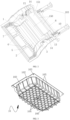
FIG. 3 is a schematic diagram showing an overall structure of the spare tire cabin according to an example of the present disclosure; -
FIG. 4 is a schematic diagram showing an overall structure of the lower vehicle body rear structure according to an example of the present disclosure from another angle of view; -
FIG. 5 is a schematic structural diagram of the lower vehicle body rear structure according to an example of the present disclosure after rear floor longitudinal beam rear sections are removed; -
FIG. 6 is a schematic diagram showing the structure ofFIG. 5 from another angle of view; -
FIG. 7 is a partially enlarged diagram of a portion A inFIG. 6 ; -
FIG. 8 is a schematic diagram showing a partial structure in a vehicle body according to an example of the present disclosure; and -
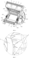
FIG. 9 is a schematic diagram showing a force transmission path when the vehicle body according to an example of the present disclosure in a collision. -
- 1. rear floor longitudinal beam; 101. rear spring mounting seat; 102. rear suspension mounting point; 103. rear floor longitudinal beam rear section;
- 2. rear floor middle cross beam; 3. rear wheel cover; 301. rear shock absorber mounting seat;
- 4. rear floor force transmission beam; 5. rear floor connecting beam; 6. rear floor rear cross beam; 7. reinforcing rib; 8. doorsill beam; 9. front floor reinforcing longitudinal beam; 10. lap-joint plate; 11. rear supporting plate; 12. inserted groove; 13. connecting seat; 14. connecting plate;
- 15. shelf; 150. bending portion; 151. upper plate; 152. lower plate; 153. cavity;
- 16. spare tire cabin; 160. spare tire cabin body; 161. accommodating chamber; 162. curled edge; 163. fixing portion; 164. reinforcing structure; 165. reinforcing rib; 166. annular rib;
- 17. rear floor cover plate; 170. reinforcing structure; and 18. storage box.
- It should be noted that examples in the present disclosure and features in the examples may be combined with each other without conflict.
- In describing the present disclosure, it should be noted that the terms "upper", "lower", "inner", "outer", and the like, if any, indicating orientations or positional relationships based on the orientations or positional relationships shown in the accompanying drawings, are merely for convenience in describing the present disclosure and simplifying the description, and do not indicate or imply that the referenced devices or elements must have a particular orientation, be constructed and operated in a particular orientation, and therefore should not be construed as limiting the present disclosure. In addition, the terms "first", "second", and the like, if present, are used for descriptive purposes only and are not to be construed as indicating or implying relative importance.
- Furthermore, in describing the present disclosure, the terms "mounting", "connecting", "connected", and "connector" are to be construed broadly, unless expressly limited otherwise. For example, it may be a fixed connection, a detachable connection, or an integral connection; it may be a mechanical connection or an electrical connection; and it may be direct connection or indirect connection through an intermediate medium, and may be internal communication between two elements. The specific meaning of the above terms in this disclosure may be understood by those of ordinary skill in the art in conjunction with a specific context.
- The present disclosure will now be described in detail in connection with examples with reference to the accompanying drawings.
- This example relates to a lower vehicle body rear structure which may improve an overall arrangement structure of a vehicle body framework of a rear portion of a vehicle, a
shelf 15, and aspare tire cabin 16. - In general, the lower vehicle body rear structure includes a rear floor integrally formed in a die-casting mode, rear floor longitudinal beam
rear sections 103 fixedly connected to the rear floor, ashelf 15, and aspare tire cabin 16;
wherein rear floorlongitudinal beams 1 arranged on two sides respectively, and a rear floormiddle cross beam 2 and a rear floorrear cross beam 6 which are connected between the rear floorlongitudinal beams 1 on the two sides are formed on the rear floor, and rear wheel covers 3 connected to the rear floorlongitudinal beams 1 on the corresponding sides are arranged on the two sides of the rear floor respectively. - The
shelf 15 is located above the rear floor, and two ends of theshelf 15 are arranged in one-to-one correspondence with the rear wheel covers 3 on the two sides and both connected to the rear wheel covers 3 by means of connectingplates 14; and at the moment, the rear floor, theshelf 15 and the two connectingplates 14 are connected to form an annular structure arranged along a height direction of a vehicle body. - Two rear floor longitudinal beam
rear sections 103 are provided to be connected to rear ends of the rear floorlongitudinal beams 1 on the two sides, arear supporting plate 11 is connected between rear ends of the two rear floor longitudinal beamrear sections 103, and thespare tire cabin 16 is arranged in a mounting space defined by the rear floor, therear supporting plate 11, and the rear floor longitudinal beamrear sections 103 on the two sides. - Based on the above design concept, an exemplary structure of the lower vehicle body rear structure of this example is shown in
FIG. 1 andFIG. 2 . As described above, the lower vehicle body rear structure mainly includes the rear floor integrally formed in the die-casting mode, the rear floor longitudinal beamrear sections 103 fixedly connected to the rear floor, theshelf 15, and thespare tire cabin 16. - The rear floor
longitudinal beams 1 arranged on the two sides respectively, and the rear floormiddle cross beam 2 connected between the rear floorlongitudinal beams 1 on the two sides are formed on the rear floor, wherein rear floorforce transmission beams 4 are formed on inner sides of the rear floorlongitudinal beams 1 on the two sides, and a rear end of each of the rear floorforce transmission beams 4 is connected to the rear floormiddle cross beam 2. In addition, the rear wheel covers 3 connected to the rear floorlongitudinal beams 1 on the corresponding sides are arranged on the two sides of the rear floorlongitudinal beams 1 respectively. - On this basis, the
shelf 15 is located above the rear floor, and two ends of theshelf 15 are arranged in one-to-one correspondence with the rear wheel covers 3 on the two sides and both connected to the rear wheel covers 3 by means of connectingplates 14. At the moment, the rear floor, theshelf 15 and the two connectingplates 14 are connected to form an annular structure arranged along the height direction of the vehicle body. - The
shelf 15 and the rear floor integrally formed are connected into a whole by means of the connectingplates 14, the annular reinforcing structure is formed in the height direction of the vehicle body, and theshelf 15 is located at an upper portion of the annular structure, so that theshelf 15 is more closely connected to a base framework of the vehicle body, thereby being conducive to the improvement of the bearing performance of theshelf 15 located at the rear portion of the vehicle. - Preferably, the
above shelf 15 is integrally formed in an extruding mode by adopting aluminum alloy, a platy structure may be adopted for theshelf 15, and a preferred structural form may be provided as follows. Theshelf 15 includes anupper plate 151 having a plurality of bendingportions 150 to be similar to a shape of steps, and alower plate 152 buckled and fixedly connected to a bottom of theupper plate 151. Acavity 153 is defined by thelower plate 152 and theupper plate 151 which are buckled together. - An integrally extruded structure is adopted for manufacturing the
shelf 15, so that theshelf 15 is convenient to machine and make, and has the advantage of weight reduction. The bendingportion 150 is arranged to form thecavity 153, thereby being conducive to the enhancement of the overall stereoscopic strength of theshelf 15. - In order to facilitate the mounting of the
shelf 15, a connectingseat 13 may be formed at a top of therear wheel cover 3, two connectingplates 14 are fixedly mounted at the connectingseats 13 of the rear wheel covers 3 on the two sides by means of riveting or screwing respectively, and the other ends of the two connectingplates 14 are fixedly connected to two ends of theshelf 15 by screwing or riveting respectively. - On the basis of the structure of the rear floor described above, rear floor longitudinal beam
rear sections 103 are also connected to rear ends of the rear floorlongitudinal beams 1 on the two sides respectively, and each of the rear floor longitudinal beamrear sections 103 are inserted with the corresponding rear floorlongitudinal beam 1 to be fixedly connected together. Preferably, the two rear floor longitudinal beamrear sections 103 are integrally formed in the extruding mode by adopting aluminum alloy. - As shown in
FIG. 3 andFIG. 4 , preferably, a structure with a cross section in a shape of a rectangle with a bar across two opposite edges of the rectangle is adopted for the rear floor longitudinal beamrear section 103. The cross section of the rear floor longitudinal beamrear section 103 adopts the structure in the shape of the rectangle with a bar across two opposite edges of the rectangle, thereby being not only convenient to machine and form, but also beneficial to the improvement of the overall strength of the rear floor longitudinal beamrear section 103 itself. - Moreover, an overhanging lap-
joint plate 10 is formed at a side portion of the rear floor longitudinal beamrear section 103; and arear supporting plate 11 may also be connected between the rear ends of the two rear floor longitudinal beamrear sections 103. By additionally arranging the structure of the lap-joint plate 10 with a curled edge at the side portion of the rear floor longitudinal beamrear section 103, the connection and matching between the rear floor longitudinal beamrear section 103 and the rear floorlongitudinal beam 1 are facilitated, thereby being beneficial to the improvement of the connecting guidance between the rear floor longitudinal beamrear section 103 and the rear floorlongitudinal beam 1. - With regard to the specific connecting mode, the rear floor
longitudinal beam 1 and the rear floor longitudinal beamrear section 103 may be fastened by matching with welding or screwing and other forms on the basis of inserting. In this example, an insertedgroove 12 is formed in a rear end of the rear floorlongitudinal beam 1, and a front end of the rear floor longitudinal beamrear section 103 is inserted into the insertedgroove 12; meanwhile, the rear floor longitudinal beamrear section 103 and the rear floorlongitudinal beam 1 are fastened and connected together by adopting a rivet. The insertedgroove 12 is formed in the rear end of the rear floorlongitudinal beam 1, and the rear floor longitudinal beamrear section 103 is fixed to the rear floorlongitudinal beam 1 by adopting an inserting mode in combination with a riveting structure, thereby not only having certain connecting firmness, but also enabling the rear floor longitudinal beamrear section 103 to be inserted into the insertedgroove 12 of the rear floorlongitudinal beam 1 after the rivet is broken when the rear portion of the vehicle encounters a great collision, so as to achieve the effect of further buffering and absorbing energy. - For the lower vehicle body rear structure of this example, by arranging the rear floor
middle cross beam 2 and the rear floorforce transmission beam 4 for matching with the rear floorlongitudinal beam 1, the force transmission path at the rear end of the vehicle is enriched and the strength of the overall structure is enhanced. Meanwhile, the rear floor longitudinal beamrear section 103 inserted at the rear end of the rear floorlongitudinal beam 1 may play a certain role in buffering and absorbing energy due to recession, deformation and retraction thereof towards the direction of the rear floorlongitudinal beam 1, thereby being beneficial to the improvement of the collision protection performance of the rear portion of the vehicle. - Two rear floor longitudinal beam
rear sections 103 are provided to be connected to rear ends of the rear floorlongitudinal beams 1 on the two sides respectively, and arear supporting plate 11 is connected between rear ends of the two rear floor longitudinal beamrear sections 103; in this manner, a mounting space is defined by the rear floor, therear supporting plate 11, and the rear floor longitudinal beamrear sections 103 on the two sides, and thespare tire cabin 16 above is arranged in the mounting space. - As also shown in
FIG. 1 in conjunction withFIG. 3 , thespare tire cabin 16 includes a sparetire cabin body 160 formed with anaccommodating chamber 161 having a top opening. A curlededge 162 which is curled outwards is formed at a periphery of a top of the sparetire cabin body 160, and the curlededge 162 is provided with a fixingportion 163 for fixing the sparetire cabin body 160 in the mounting space. The fixingportion 163 may be a mounting hole formed in the curlededge 162. The curlededge 162 is arranged at the top of the sparetire cabin body 160, so that the lap-joint plate 10 may be conveniently lapped on a frame defined by the rear floor, the rear floor longitudinal beamrear sections 103, and therear supporting plate 11; and by arranging the fixingportion 163 on the curlededge 162, the fastening and mounting of thespare tire cabin 16 may be completed in a manner of matching the mounting hole with a screw. - Preferably, a plastic part integrally formed in an injection molding mode is adopted for the
spare tire cabin 16, thereby having the advantages of mature process and convenience in machining and molding. With regard to a specific structure on the sparetire cabin body 160, the following solution may be adopted. - A reinforcing
structure 164 protruding downwards is formed on the bottom end surface of the sparetire cabin body 160, and the reinforcingstructure 164 may be designed as a convex rib structure distributed in a honeycomb shape. Reinforcingribs 165 protruding outwards may also be arranged on an outer side wall of the sparetire cabin body 160, and a plurality of reinforcingribs 165 are provided to be distributed at intervals along a circumferential direction of the sparetire cabin body 160. - Meanwhile, in this example, an
annular rib 166 protruding downwards is formed on the bottom end surface of the sparetire cabin body 160, and the reinforcingstructure 164 above is located inside theannular rib 166; and the reinforcingstructure 164 is connected to an inner wall of theannular rib 166. A bottom end of the reinforcingrib 165 extends to the bottom end surface of the sparetire cabin body 160 and connected to an outer wall of theannular rib 166. Through the matching of the reinforcing structures such as the reinforcingstructure 164, the reinforcingrib 165 and theannular rib 166, the overall strength of thespare tire cabin 16 may be greatly improved, thereby being beneficial to the improvement of the bearing performance of thespare tire cabin 16. - In addition, a rear
floor cover plate 17 may be additionally arranged in an area between the rear floormiddle cross beam 2 and the rear floorrear cross beam 6 on a framework formed on the basis of the rear floor to isolate a driving cabin from the outside. A sheet metal part or injection molded part may be adopted for the rearfloor cover plate 17, and convex reinforcingstructures 170 with different patterns may be constructed on the rearfloor cover plate 17. - In order to make full use of a space outside the rear floor longitudinal beam
rear section 103, astorage box 18 may be arranged here, and thestorage box 18 is fixed to the rear floor longitudinal beamrear section 103 and therear wheel cover 3 by means of riveting or screwing. The overall shape of the space is relatively foursquare, thereby facilitating the storage of small-sized debris. - According to the lower vehicle body rear structure of the present disclosure, the
shelf 15 and the rear floor integrally formed are connected into a whole by means of the connectingplates 14, and the annular reinforcing structure is formed in the height direction of the vehicle body, so that the bearing performance of theshelf 15 located at the rear portion of the vehicle may be improved; thespare tire cabin 16 is mounted in the space defined by the rear floor, the rear floor longitudinal beamrear sections 103, and therear supporting plate 11, so that thespare tire cabin 16 has a stable bearing foundation; meanwhile, by integrally forming a plurality of beam body structures in the vehicle body framework on the rear floor, the structural compactness and assembly efficiency of the vehicle body framework are improved, so that the overall arrangement structure of the vehicle body framework of the rear portion of the vehicle, theshelf 15, and thespare tire cabin 16 is improved. - On a main structure of the rear floor, as shown in
FIG. 4 and FIG. 5 , the rear floorlongitudinal beam 1 and the rear floorforce transmission beam 4 on each side are connected by means of the rear floormiddle cross beam 2 to form a herringbone-shaped force transmission passage. - It should be noted that the herringbone-shaped shape in this example, namely the shape as shown in
FIG. 4 , the rear floorlongitudinal beam 1 and the rear floorforce transmission beam 4 on each side which are connected by means of the rear floormiddle cross beam 2 resemble a herringbone-shaped structure in the overall visual sense. - In addition, the rear floor
middle cross beam 2 in this example may also form an auxiliary force transmission passage between the rear floorlongitudinal beams 1, thereby further enhancing the force transmission and decomposition effects of the rear floor structure. Based on the above overall description, for the lower vehicle body rear structure of this example, as a preferred embodiment, as shown inFIG. 4 to FIG. 6 , a rearfloor connecting beam 5 is also formed at a front end of the rear floor, the rearfloor connecting beam 5 is connected between the rear floorlongitudinal beams 1 on the two sides, and a front end of each of the rear floorforce transmission beams 4 is connected to the rearfloor connecting beam 5. - Preferably, as also shown in
FIG. 4 to FIG. 6 , in this example, a rear floorrear cross beam 6 is formed near the rear end of the rear floor, and the rear floorrear cross beam 6 is connected between the rear floorlongitudinal beams 1 on the two sides. The rear floorrear cross beam 6 may form another force transmission passage between the rear floorlongitudinal beams 1 on the two sides in a stressed process of the rear floor structure of this example, and is matched with the force transmission passage formed between the rear floormiddle cross beam 2 and the rear floorlongitudinal beams 1 on the two sides, thereby improving the force transmission and decomposition effects of the rear floor structure, and reducing the risk of bending of the rear floor structure. - That is, in the case of a collision, for the rear floor structure of this example, the force dispersion and transmission may be achieved by the herringbone-shaped force transmission passage, and the force dispersion and transmission may be achieved once again by the auxiliary force transmission passage formed by the rear floor
middle cross beam 2 and the rear floorrear cross beam 6 respectively, so that the overall force transmission and decomposition effects of the rear floor structure may be effectively improved. - In this example, it should be noted that the rear wheel covers 3 described above may be integrally formed in the die-casting mode with the rear floor
longitudinal beams 1, or the rear wheel covers 3 may also be separately formed and then connected to the rear floorlongitudinal beams 1, and preferably the rear wheel covers 3 are integrally formed in the die-casting mode with the rear floorlongitudinal beams 1. - As shown in
FIG. 4 andFIG. 6 , a rearspring mounting seat 101 is formed on the rear floorlongitudinal beams 1 on the two sides respectively, and a rear shockabsorber mounting seat 301 is formed on the rear wheel covers 3 on the two sides respectively. The specific structural design of the rearspring mounting seat 101 and the rear shockabsorber mounting seat 301 may refer to relevant structural portions of the lower vehicle body rear structure in the prior art, and in the specific structural design, it is necessary to ensure adaptation to mounting positions of a rear shock absorbing spring and a rear shock absorber which are configured. - In specific implementation of this example, rear
suspension mounting points 102 are arranged on the rear floorlongitudinal beams 1 on the two sides respectively for mounting a rear suspension, and two rearsuspension mounting points 102 are provided to be arranged at intervals on the rear floorlongitudinal beam 1 on each side. Of course, the positional arrangement of the two rearsuspension mounting points 102 may be adjusted and set accordingly according to actual mounting requirements or vehicle body design requirements, and it is only necessary to ensure that the assembly of corresponding suspension members is facilitated. As shown inFIG. 6 , the two rearsuspension mounting points 102 are arranged at positions adjacent to an upper end and a lower end of therear wheel cover 3 respectively. - In addition, a reinforcing
rib 7 is formed on at least one of the rear floorlongitudinal beams 1, the rear floormiddle cross beam 2, the rear wheel covers 3, the rear floorforce transmission beams 4, the rearfloor connecting beam 5, and the rear floorrear cross beam 6 to improve the local rigidity of the rear floor structure.FIG. 4 to FIG. 7 show an illustration in which the reinforcingribs 7 are formed on all of the rear floorlongitudinal beams 1, the rear floormiddle cross beam 2, the rear wheel covers 3, the rear floorforce transmission beams 4, the rearfloor connecting beam 5, and the rear floorrear cross beam 6. - It is worth mentioning that the above reinforcing
ribs 7 may be designed in an arrangement position and structure adapted to the rigidity requirements of corresponding portions in the rear floor structure. In the design of the arrangement position, taking the rear floormiddle cross beam 2 shown inFIG. 5 andFIG. 6 for example, a plurality of reinforcingribs 7 are arranged on the two sides of the rear floormiddle cross beam 2. In the structural design, for example, the rigidity reinforcing effect of the reinforcingribs 7 may be improved by increasing a wall thickness, and the reinforcing effect on the rear floor structure may also be improved by increasing the reinforcingribs 7 or improving the structural design of the reinforcingribs 7. - In addition, in order to improve the weight reduction of the whole vehicle, the rear floor in this example is integrally formed in the die-casting mode by adopting cast aluminum, and compared with the conventional rear floor structure made of sheet metal, the weight of the rear floor structure made of the cast aluminum material may be reduced by about 20%. According to the lower vehicle body rear structure of this example, the rear floor is integrally formed in the die-casting mode, so that the structural rigidity of the lower vehicle body rear structure may be effectively improved, meanwhile, by arranging the rear floor
force transmission beam 4, the herringbone-shaped force transmission passage may also be formed by matching with the rear floorlongitudinal beam 1 and the rear floormiddle cross beam 2, and then a force on the rear floorlongitudinal beam 1 may be effectively transmitted and decomposed, thereby effectively reducing the risk of bending in the event of a collision. - In addition, the rear floor is integrally formed in the die-casting mode by adopting the aluminum material, so that the rear floor is simple in connecting mode, small in quantity of parts, high in size precision, convenient to machine and manufacture, and beneficial to achieving the weight reduction of the overall structure.
- When the lower vehicle body rear structure described above is applied in the vehicle, as shown in
FIG. 8 , in the vehicle body of vehicle of this example, a front floor reinforcinglongitudinal beams 9 are arranged betweendoorsill beams 8 on the two sides, and a plurality of front floor reinforcinglongitudinal beams 9 are provided to be arranged in one-to-one correspondence with each of the rear floor force transmission beams 4. - Wherein the front floor reinforcing
longitudinal beams 9 form a longitudinal force transmission structure passing through a middle portion of the whole vehicle, and in the specific implementation, the rearfloor connecting beam 5 in the rear floor is lapped to the front floor rear cross beam structure between the rear ends of the doorsill beams 8 on the two sides. At the moment, due to the connection, force transmission connection is formed between the rear floorlongitudinal beam 1 and thedoorsill beam 8 on each side, and force transmission connection is also formed between each of the rear floorforce transmission beams 4 and the corresponding front floor reinforcinglongitudinal beam 9. - Thus, when the vehicle encounters a rear collision, a stressed process of the vehicle body may refer to
FIG. 9 . A collision force is transmitted forwards along the rear floorlongitudinal beam 1, and then the herringbone-shaped force transmission passage formed by the rear floorlongitudinal beam 1 and the adjacent rear floorforce transmission beam 4 on each side further divides the collision force into two parts, one part of which is transmitted to thedoorsill beam 8 on the corresponding side via the rear floorlongitudinal beam 1, and the other part of which is transmitted to the corresponding front floor reinforcinglongitudinal beam 9 via the rear floorforce transmission beam 4. - In addition, as both the rear floor
middle cross beam 2 and the rear floorrear cross beam 6 are connected to the rear floorlongitudinal beams 1 on the two sides, and two auxiliary force transmission passages are also formed, a part of the collision force is also transmitted and decomposed via the two auxiliary force transmission passages. - It can be seen therefrom that by adopting the lower vehicle body rear structure of this example, the structural rigidity of the rear floor structure may be effectively improved, and the force transmission path of the vehicle body structure may be optimized, thereby effectively improving the structural rigidity of the overall vehicle body structure of the vehicle, improving the force transmission and decomposition effects of the vehicle body structure, and effectively improving the safety of the vehicle.
- Finally, this example further relates to a vehicle, wherein a vehicle body of the vehicle is provided with the lower vehicle body rear structure as described above.
- While the foregoing is directed to the preferred examples of the present disclosure, the present disclosure is not limited to the disclosed examples. Any modification, equivalent and improvement made within the spirit and principle of the present disclosure shall be included in the protection scope of the present disclosure.
Claims (15)
- A lower vehicle body rear structure, characterized in that the lower vehicle body rear structure comprises:a rear floor integrally formed in a die-casting mode, rear floor longitudinal beam rear sections (103) fixedly connected to the rear floor, a shelf (15), and a spare tire cabin (16);wherein the rear floor is formed with rear floor longitudinal beams (1) arranged on two sides of the rear floor, and a rear floor middle cross beam (2) and a rear floor rear cross beam (6) which are connected between the rear floor longitudinal beams (1) on the two sides; and rear wheel covers (3) respectively connected to the rear floor longitudinal beams (1) on the corresponding sides are arranged on the two sides of the rear floor;the shelf (15) is located above the rear floor, and two ends of the shelf (15) are arranged in one-to-one correspondence with the rear wheel covers (3) on the two sides and both connected to the corresponding rear wheel covers (3) respectively by means of connecting plates (14); and the rear floor, the shelf (15) and the two connecting plates (14) are connected to form an annular structure arranged along a height direction of a vehicle body; anda number of the rear floor longitudinal beam rear sections (103) is two, and the rear floor longitudinal beam rear sections (103) are connected to rear ends of the rear floor longitudinal beams (1) on the two sides, a rear supporting plate (11) is connected between rear ends of the two rear floor longitudinal beam rear sections (103), and the spare tire cabin (16) is arranged in a mounting space defined by the rear floor, the rear supporting plate (11), and the rear floor longitudinal beam rear sections (103) on the two sides.
- The lower vehicle body rear structure according to claim 1, characterized in thatrear floor force transmission beams (4) are formed on inner sides of the rear floor longitudinal beams (1) on the two sides;a rear end of each of the rear floor force transmission beams (4) is connected to the rear floor middle cross beam (2); andthe rear floor longitudinal beam (1) and the rear floor force transmission beam (4) on each side are connected by means of the rear floor middle cross beam (2) to form a herringbone-shaped force transmission passage.
- The lower vehicle body rear structure according to claim 2, characterized in thata rear floor connecting beam (5) is formed at a front end of the rear floor;the rear floor connecting beam (5) is connected between the rear floor longitudinal beams (1) on the two sides; anda front end of each of the rear floor force transmission beams (4) is connected to the rear floor connecting beam (5).
- The lower vehicle body rear structure according to claim 3, characterized in that
a reinforcing rib (7) is formed on at least one of the rear floor longitudinal beams (1), the rear floor middle cross beam (2), the rear wheel covers (3), the rear floor force transmission beams (4), the rear floor connecting beam (5), and the rear floor rear cross beam (6). - The lower vehicle body rear structure according to claim 1, characterized in that
a rear spring mounting seat (101) is formed on the rear floor longitudinal beams (1) on the two sides, respectively. - The lower vehicle body rear structure according to claim 1, characterized in that
a rear shock absorber mounting seat (301) is formed on the rear wheel covers (3) on the two sides, respectively. - The lower vehicle body rear structure according to claim 1, characterized in thatthe rear floor longitudinal beam rear section (103) is integrally formed in an extruding mode;a cross section of the rear floor longitudinal beam rear section (103) is in a shape of a rectangle with a bar across two opposite edges of the rectangle; andan overhanging lap-joint plate (10) is formed at a side portion of the rear floor longitudinal beam rear section (103).
- The lower vehicle body rear structure according to claim 1, characterized in thatan inserted groove (12) is formed in the rear end of the rear floor longitudinal beam (1); andeach of the rear floor longitudinal beam rear sections (103) and the corresponding rear floor longitudinal beam (1) are inserted to be fixedly connected together.
- The lower vehicle body rear structure according to claim 1, characterized in thatthe shelf (15) comprises an upper plate (151), and a lower plate (152) buckled and fixedly connected to a bottom of the upper plate (151);the upper plate (151) is provided with a plurality of bending portions (150) to be similar to a shape of steps; anda cavity (153) is defined by the lower plate (152) and the upper plate (151).
- The lower vehicle body rear structure according to claim 9, characterized in thata connecting seat (13) is formed at a top of the rear wheel cover (3);one end of the connecting plate (14) connected to the rear wheel cover (3) is connected to the connecting seat (13); andone end of the connecting plate (14) connected to the shelf (15) is connected to a bottom of the lower plate (152).
- The lower vehicle body rear structure according to claim 1, characterized in thatthe spare tire cabin (16) comprises a spare tire cabin body (160) formed with an accommodating chamber (161) having a top opening;a curled edge (162) curled outwards is formed at a top of the spare tire cabin body (160), and the curled edge (162) is provided with a fixing portion (163) for fixing the spare tire cabin body (160) in the mounting space; anda reinforcing structure (164) protruding downwards is formed on a bottom end surface of the spare tire cabin body (160), and the reinforcing structure (164) is in a honeycomb shape.
- The lower vehicle body rear structure according to claim 11, characterized in thatreinforcing ribs (165) protruding outwards are formed on an outer side wall of the spare tire cabin body (160); anda number of the reinforcing ribs (165) is more than one, and the reinforcing ribs (165) are distributed at intervals along a circumferential direction of the spare tire cabin body (160).
- The lower vehicle body rear structure according to claim 12, characterized in thatan annular rib (166) protruding downwards is formed on the bottom end surface of the spare tire cabin body (160);the reinforcing structure (164) is located inside the annular rib (166) and connected to an inner wall of the annular rib (166); anda bottom end of the reinforcing rib (165) extends to the bottom end surface of the spare tire cabin body (160) and connected to an outer wall of the annular rib (166).
- The lower vehicle body rear structure according to any one of claims 1 to 13, characterized in thatthe rear floor is integrally formed in the die-casting mode by adopting cast aluminum;the shelf (15) is integrally formed in an extruding mode by adopting aluminum alloy; andthe spare tire cabin (16) is integrally formed in an injection molding mode.
- A vehicle, characterized in that a vehicle body of the vehicle is provided with the lower vehicle body rear structure according to any one of claims 1 to 14.
Applications Claiming Priority (2)
| Application Number | Priority Date | Filing Date | Title |
|---|---|---|---|
| CN202110931743.0A CN114789754B (en) | 2021-08-13 | 2021-08-13 | Lower rear structure |
| PCT/CN2022/101484 WO2023016106A1 (en) | 2021-08-13 | 2022-06-27 | Lower vehicle body rear structure and vehicle |
Publications (3)
| Publication Number | Publication Date |
|---|---|
| EP4385862A1 true EP4385862A1 (en) | 2024-06-19 |
| EP4385862A4 EP4385862A4 (en) | 2024-11-27 |
| EP4385862B1 EP4385862B1 (en) | 2025-12-10 |
Family
ID=82459658
Family Applications (1)
| Application Number | Title | Priority Date | Filing Date |
|---|---|---|---|
| EP22855091.9A Active EP4385862B1 (en) | 2021-08-13 | 2022-06-27 | Lower vehicle body rear structure and vehicle |
Country Status (4)
| Country | Link |
|---|---|
| US (1) | US20250121890A1 (en) |
| EP (1) | EP4385862B1 (en) |
| CN (1) | CN114789754B (en) |
| WO (1) | WO2023016106A1 (en) |
Cited By (2)
| Publication number | Priority date | Publication date | Assignee | Title |
|---|---|---|---|---|
| EP4570628A1 (en) * | 2023-12-13 | 2025-06-18 | Hyundai Motor Company | Rear frame for vehicle |
| CN121671738A (en) * | 2026-02-09 | 2026-03-17 | 浙江零跑科技股份有限公司 | Rear longitudinal beam frame structure and vehicle |
Families Citing this family (15)
| Publication number | Priority date | Publication date | Assignee | Title |
|---|---|---|---|---|
| KR20230169529A (en) * | 2022-06-08 | 2023-12-18 | 현대자동차주식회사 | Rear vehicle body structure |
| CN117508346A (en) * | 2022-07-29 | 2024-02-06 | 比亚迪股份有限公司 | vehicle |
| CN115257971A (en) * | 2022-08-30 | 2022-11-01 | 浙江吉利控股集团有限公司 | Rear floor assembly and vehicle |
| CN115416759B (en) * | 2022-08-30 | 2023-11-24 | 重庆长安汽车股份有限公司 | Floor structure behind platform car body and vehicle |
| CN116039774B (en) * | 2022-11-30 | 2025-05-27 | 重庆长安汽车股份有限公司 | Rear floor assembly |
| JP7690945B2 (en) * | 2022-12-26 | 2025-06-11 | トヨタ自動車株式会社 | Rear component for vehicle |
| CN118683640A (en) * | 2023-03-23 | 2024-09-24 | 本田技研工业株式会社 | Rear side structure |
| CN118810932A (en) * | 2023-04-19 | 2024-10-22 | 本田技研工业株式会社 | Vehicle rear structure |
| CN116552653A (en) * | 2023-06-16 | 2023-08-08 | 奇瑞新能源汽车股份有限公司 | New energy automobile body assembly, automobile body assembly and whole automobile preparation method |
| CN117087769B (en) * | 2023-08-22 | 2025-09-30 | 重庆长安汽车股份有限公司 | An adjustable steel-aluminum hybrid automobile rear floor assembly |
| CN116923258B (en) * | 2023-08-29 | 2025-08-26 | 重庆长安汽车股份有限公司 | Front trunk structure and vehicle |
| CN117104352B (en) * | 2023-09-13 | 2025-11-25 | 广州汽车集团股份有限公司 | The rear floor of the vehicle body and the vehicle with it |
| EP4686641A1 (en) * | 2024-08-01 | 2026-02-04 | Stellantis Automoveis Brasil Ltda | Reinforcement structure of a motor vehicle rear side panel and vehicle |
| JP2026044111A (en) * | 2024-08-29 | 2026-03-12 | 本田技研工業株式会社 | Vehicle structure |
| JP2026044112A (en) * | 2024-08-29 | 2026-03-12 | 本田技研工業株式会社 | Vehicle structure |
Family Cites Families (14)
| Publication number | Priority date | Publication date | Assignee | Title |
|---|---|---|---|---|
| JPH06211167A (en) * | 1993-01-18 | 1994-08-02 | Toyota Motor Corp | Rear body structure for automobile |
| KR100579095B1 (en) * | 2003-11-18 | 2006-05-12 | 현대자동차주식회사 | Arrangement structure of the rear floor side member |
| KR20070082736A (en) * | 2006-02-17 | 2007-08-22 | 현대자동차주식회사 | Rear floor assembly of the vehicle |
| JP5207130B2 (en) * | 2008-09-24 | 2013-06-12 | スズキ株式会社 | Car body rear structure |
| CN104670335A (en) * | 2015-03-17 | 2015-06-03 | 安徽江淮汽车股份有限公司 | Automobile body and automobile |
| JP6462554B2 (en) * | 2015-10-27 | 2019-01-30 | 本田技研工業株式会社 | Car body rear structure |
| CN207060175U (en) * | 2017-08-01 | 2018-03-02 | 广州汽车集团股份有限公司 | Rear structure of vehicle body and automobile |
| CN208036448U (en) * | 2018-04-20 | 2018-11-02 | 广州汽车集团股份有限公司 | A kind of automobile rear floor frame |
| CN209008696U (en) * | 2018-10-19 | 2019-06-21 | 广州汽车集团股份有限公司 | A rear floor frame structure and automobile |
| CN111098933B (en) * | 2018-10-29 | 2021-09-21 | 长沙市比亚迪汽车有限公司 | Vehicle body rear structure and vehicle |
| CN209667244U (en) * | 2019-01-24 | 2019-11-22 | 广州汽车集团股份有限公司 | Automobile spare tire compartment structure and automobile |
| JP7379934B2 (en) * | 2019-08-26 | 2023-11-15 | マツダ株式会社 | Vehicle rear structure |
| CN111806575B (en) * | 2020-06-11 | 2021-05-28 | 浙江零跑科技有限公司 | C-ring structure of new energy vehicles |
| JP7303843B2 (en) * | 2021-05-26 | 2023-07-05 | 本田技研工業株式会社 | vehicle rear structure |
-
2021
- 2021-08-13 CN CN202110931743.0A patent/CN114789754B/en active Active
-
2022
- 2022-06-27 US US18/682,146 patent/US20250121890A1/en active Pending
- 2022-06-27 EP EP22855091.9A patent/EP4385862B1/en active Active
- 2022-06-27 WO PCT/CN2022/101484 patent/WO2023016106A1/en not_active Ceased
Cited By (2)
| Publication number | Priority date | Publication date | Assignee | Title |
|---|---|---|---|---|
| EP4570628A1 (en) * | 2023-12-13 | 2025-06-18 | Hyundai Motor Company | Rear frame for vehicle |
| CN121671738A (en) * | 2026-02-09 | 2026-03-17 | 浙江零跑科技股份有限公司 | Rear longitudinal beam frame structure and vehicle |
Also Published As
| Publication number | Publication date |
|---|---|
| CN114789754A (en) | 2022-07-26 |
| EP4385862A4 (en) | 2024-11-27 |
| CN114789754B (en) | 2024-05-24 |
| EP4385862B1 (en) | 2025-12-10 |
| WO2023016106A1 (en) | 2023-02-16 |
| US20250121890A1 (en) | 2025-04-17 |
Similar Documents
| Publication | Publication Date | Title |
|---|---|---|
| US20250121890A1 (en) | Lower vehicle body rear structure and vehicle | |
| EP4385859A1 (en) | Lower vehicle body front structure and vehicle | |
| EP4385858A1 (en) | Lower vehicle body middle structure and vehicle | |
| CN215883809U (en) | Rear end reinforcing structure of vehicle body | |
| CN115703508B (en) | Automobile body structure | |
| CN215883808U (en) | Rear end structure of vehicle body | |
| CN215883811U (en) | Floor skeleton texture and car behind car | |
| CN114802454A (en) | New energy automobile lightweight collision energy-absorbing aluminum alloy sub vehicle frame | |
| CN219948349U (en) | Vehicle body assembly and vehicle | |
| CN215883806U (en) | Vehicle body front end collision energy-absorbing structure | |
| CN218858529U (en) | Body rear truss structure and automobile | |
| CN216916059U (en) | Vehicle rear longitudinal beam, vehicle rear floor assembly, vehicle body frame and vehicle | |
| CN217100187U (en) | Front engine room structure | |
| CN115303368A (en) | Automobile cabin sub-assembly structure | |
| CN109560218B (en) | Lower shell for battery pack and battery pack | |
| CN221928386U (en) | Battery pack mounting beam, battery pack and vehicle | |
| CN217100182U (en) | Automobile body top cover crossbeam and automobile body | |
| CN217294664U (en) | New energy automobile lightweight collision energy-absorbing aluminum alloy sub vehicle frame | |
| CN217100172U (en) | Rear anti-collision beam and vehicle | |
| CN222698584U (en) | Vehicle and rear cabin frame structure thereof | |
| CN220577371U (en) | Connection structure, anti-collision mechanism and vehicle | |
| CN210591746U (en) | Anti-impact high-strength beam for heavy-duty car | |
| CN222698581U (en) | Vehicle and its rear cabin superstructure | |
| CN223058959U (en) | Automobile front anti-collision beam and automobile | |
| CN222654196U (en) | Battery box assembly and vehicle with same |
Legal Events
| Date | Code | Title | Description |
|---|---|---|---|
| STAA | Information on the status of an ep patent application or granted ep patent |
Free format text: STATUS: THE INTERNATIONAL PUBLICATION HAS BEEN MADE |
|
| PUAI | Public reference made under article 153(3) epc to a published international application that has entered the european phase |
Free format text: ORIGINAL CODE: 0009012 |
|
| STAA | Information on the status of an ep patent application or granted ep patent |
Free format text: STATUS: REQUEST FOR EXAMINATION WAS MADE |
|
| 17P | Request for examination filed |
Effective date: 20240308 |
|
| AK | Designated contracting states |
Kind code of ref document: A1 Designated state(s): AL AT BE BG CH CY CZ DE DK EE ES FI FR GB GR HR HU IE IS IT LI LT LU LV MC MK MT NL NO PL PT RO RS SE SI SK SM TR |
|
| DAV | Request for validation of the european patent (deleted) | ||
| DAX | Request for extension of the european patent (deleted) | ||
| A4 | Supplementary search report drawn up and despatched |
Effective date: 20241029 |
|
| RIC1 | Information provided on ipc code assigned before grant |
Ipc: B62D 21/02 20060101ALI20241023BHEP Ipc: B62D 25/20 20060101AFI20241023BHEP |
|
| GRAP | Despatch of communication of intention to grant a patent |
Free format text: ORIGINAL CODE: EPIDOSNIGR1 |
|
| STAA | Information on the status of an ep patent application or granted ep patent |
Free format text: STATUS: GRANT OF PATENT IS INTENDED |
|
| INTG | Intention to grant announced |
Effective date: 20250711 |
|
| P01 | Opt-out of the competence of the unified patent court (upc) registered |
Free format text: CASE NUMBER: UPC_APP_7227_4385862/2025 Effective date: 20250916 |
|
| GRAS | Grant fee paid |
Free format text: ORIGINAL CODE: EPIDOSNIGR3 |
|
| GRAA | (expected) grant |
Free format text: ORIGINAL CODE: 0009210 |
|
| STAA | Information on the status of an ep patent application or granted ep patent |
Free format text: STATUS: THE PATENT HAS BEEN GRANTED |
|
| AK | Designated contracting states |
Kind code of ref document: B1 Designated state(s): AL AT BE BG CH CY CZ DE DK EE ES FI FR GB GR HR HU IE IS IT LI LT LU LV MC MK MT NL NO PL PT RO RS SE SI SK SM TR |
|
| REG | Reference to a national code |
Ref country code: CH Ref legal event code: F10 Free format text: ST27 STATUS EVENT CODE: U-0-0-F10-F00 (AS PROVIDED BY THE NATIONAL OFFICE) Effective date: 20251210 Ref country code: GB Ref legal event code: FG4D |
|
| REG | Reference to a national code |
Ref country code: DE Ref legal event code: R096 Ref document number: 602022026778 Country of ref document: DE Ref country code: IE Ref legal event code: FG4D |
|
| PG25 | Lapsed in a contracting state [announced via postgrant information from national office to epo] |
Ref country code: ES Free format text: LAPSE BECAUSE OF FAILURE TO SUBMIT A TRANSLATION OF THE DESCRIPTION OR TO PAY THE FEE WITHIN THE PRESCRIBED TIME-LIMIT Effective date: 20251210 |
|
| REG | Reference to a national code |
Ref country code: LT Ref legal event code: MG9D |
|
| PG25 | Lapsed in a contracting state [announced via postgrant information from national office to epo] |
Ref country code: NO Free format text: LAPSE BECAUSE OF FAILURE TO SUBMIT A TRANSLATION OF THE DESCRIPTION OR TO PAY THE FEE WITHIN THE PRESCRIBED TIME-LIMIT Effective date: 20260310 |
|
| PG25 | Lapsed in a contracting state [announced via postgrant information from national office to epo] |
Ref country code: FI Free format text: LAPSE BECAUSE OF FAILURE TO SUBMIT A TRANSLATION OF THE DESCRIPTION OR TO PAY THE FEE WITHIN THE PRESCRIBED TIME-LIMIT Effective date: 20251210 Ref country code: HR Free format text: LAPSE BECAUSE OF FAILURE TO SUBMIT A TRANSLATION OF THE DESCRIPTION OR TO PAY THE FEE WITHIN THE PRESCRIBED TIME-LIMIT Effective date: 20251210 |
|
| REG | Reference to a national code |
Ref country code: NL Ref legal event code: MP Effective date: 20251210 |
|
| PG25 | Lapsed in a contracting state [announced via postgrant information from national office to epo] |
Ref country code: RS Free format text: LAPSE BECAUSE OF FAILURE TO SUBMIT A TRANSLATION OF THE DESCRIPTION OR TO PAY THE FEE WITHIN THE PRESCRIBED TIME-LIMIT Effective date: 20260310 |
|
| PG25 | Lapsed in a contracting state [announced via postgrant information from national office to epo] |
Ref country code: LV Free format text: LAPSE BECAUSE OF FAILURE TO SUBMIT A TRANSLATION OF THE DESCRIPTION OR TO PAY THE FEE WITHIN THE PRESCRIBED TIME-LIMIT Effective date: 20251210 |
|
| PG25 | Lapsed in a contracting state [announced via postgrant information from national office to epo] |
Ref country code: BG Free format text: LAPSE BECAUSE OF FAILURE TO SUBMIT A TRANSLATION OF THE DESCRIPTION OR TO PAY THE FEE WITHIN THE PRESCRIBED TIME-LIMIT Effective date: 20251210 |