EP4385842A1 - Brake system and vehicle having same - Google Patents
Brake system and vehicle having same Download PDFInfo
- Publication number
- EP4385842A1 EP4385842A1 EP22891953.6A EP22891953A EP4385842A1 EP 4385842 A1 EP4385842 A1 EP 4385842A1 EP 22891953 A EP22891953 A EP 22891953A EP 4385842 A1 EP4385842 A1 EP 4385842A1
- Authority
- EP
- European Patent Office
- Prior art keywords
- master cylinder
- brake
- assembly
- housing
- cylinder piston
- Prior art date
- Legal status (The legal status is an assumption and is not a legal conclusion. Google has not performed a legal analysis and makes no representation as to the accuracy of the status listed.)
- Pending
Links
Images


Classifications
-
- B—PERFORMING OPERATIONS; TRANSPORTING
- B60—VEHICLES IN GENERAL
- B60T—VEHICLE BRAKE CONTROL SYSTEMS OR PARTS THEREOF; BRAKE CONTROL SYSTEMS OR PARTS THEREOF, IN GENERAL; ARRANGEMENT OF BRAKING ELEMENTS ON VEHICLES IN GENERAL; PORTABLE DEVICES FOR PREVENTING UNWANTED MOVEMENT OF VEHICLES; VEHICLE MODIFICATIONS TO FACILITATE COOLING OF BRAKES
- B60T13/00—Transmitting braking action from initiating means to ultimate brake actuator with power assistance or drive; Brake systems incorporating such transmitting means, e.g. air-pressure brake systems
- B60T13/10—Transmitting braking action from initiating means to ultimate brake actuator with power assistance or drive; Brake systems incorporating such transmitting means, e.g. air-pressure brake systems with fluid assistance, drive, or release
- B60T13/12—Transmitting braking action from initiating means to ultimate brake actuator with power assistance or drive; Brake systems incorporating such transmitting means, e.g. air-pressure brake systems with fluid assistance, drive, or release the fluid being liquid
- B60T13/14—Transmitting braking action from initiating means to ultimate brake actuator with power assistance or drive; Brake systems incorporating such transmitting means, e.g. air-pressure brake systems with fluid assistance, drive, or release the fluid being liquid using accumulators or reservoirs fed by pumps
-
- B—PERFORMING OPERATIONS; TRANSPORTING
- B60—VEHICLES IN GENERAL
- B60T—VEHICLE BRAKE CONTROL SYSTEMS OR PARTS THEREOF; BRAKE CONTROL SYSTEMS OR PARTS THEREOF, IN GENERAL; ARRANGEMENT OF BRAKING ELEMENTS ON VEHICLES IN GENERAL; PORTABLE DEVICES FOR PREVENTING UNWANTED MOVEMENT OF VEHICLES; VEHICLE MODIFICATIONS TO FACILITATE COOLING OF BRAKES
- B60T13/00—Transmitting braking action from initiating means to ultimate brake actuator with power assistance or drive; Brake systems incorporating such transmitting means, e.g. air-pressure brake systems
- B60T13/10—Transmitting braking action from initiating means to ultimate brake actuator with power assistance or drive; Brake systems incorporating such transmitting means, e.g. air-pressure brake systems with fluid assistance, drive, or release
- B60T13/12—Transmitting braking action from initiating means to ultimate brake actuator with power assistance or drive; Brake systems incorporating such transmitting means, e.g. air-pressure brake systems with fluid assistance, drive, or release the fluid being liquid
- B60T13/14—Transmitting braking action from initiating means to ultimate brake actuator with power assistance or drive; Brake systems incorporating such transmitting means, e.g. air-pressure brake systems with fluid assistance, drive, or release the fluid being liquid using accumulators or reservoirs fed by pumps
- B60T13/148—Arrangements for pressure supply
-
- B—PERFORMING OPERATIONS; TRANSPORTING
- B60—VEHICLES IN GENERAL
- B60T—VEHICLE BRAKE CONTROL SYSTEMS OR PARTS THEREOF; BRAKE CONTROL SYSTEMS OR PARTS THEREOF, IN GENERAL; ARRANGEMENT OF BRAKING ELEMENTS ON VEHICLES IN GENERAL; PORTABLE DEVICES FOR PREVENTING UNWANTED MOVEMENT OF VEHICLES; VEHICLE MODIFICATIONS TO FACILITATE COOLING OF BRAKES
- B60T7/00—Brake-action initiating means
- B60T7/02—Brake-action initiating means for personal initiation
- B60T7/04—Brake-action initiating means for personal initiation foot actuated
- B60T7/042—Brake-action initiating means for personal initiation foot actuated by electrical means, e.g. using travel or force sensors
-
- B—PERFORMING OPERATIONS; TRANSPORTING
- B60—VEHICLES IN GENERAL
- B60T—VEHICLE BRAKE CONTROL SYSTEMS OR PARTS THEREOF; BRAKE CONTROL SYSTEMS OR PARTS THEREOF, IN GENERAL; ARRANGEMENT OF BRAKING ELEMENTS ON VEHICLES IN GENERAL; PORTABLE DEVICES FOR PREVENTING UNWANTED MOVEMENT OF VEHICLES; VEHICLE MODIFICATIONS TO FACILITATE COOLING OF BRAKES
- B60T11/00—Transmitting braking action from initiating means to ultimate brake actuator without power assistance or drive or where such assistance or drive is irrelevant
- B60T11/10—Transmitting braking action from initiating means to ultimate brake actuator without power assistance or drive or where such assistance or drive is irrelevant transmitting by fluid means, e.g. hydraulic
- B60T11/16—Master control, e.g. master cylinders
- B60T11/18—Connection thereof to initiating means
-
- B—PERFORMING OPERATIONS; TRANSPORTING
- B60—VEHICLES IN GENERAL
- B60T—VEHICLE BRAKE CONTROL SYSTEMS OR PARTS THEREOF; BRAKE CONTROL SYSTEMS OR PARTS THEREOF, IN GENERAL; ARRANGEMENT OF BRAKING ELEMENTS ON VEHICLES IN GENERAL; PORTABLE DEVICES FOR PREVENTING UNWANTED MOVEMENT OF VEHICLES; VEHICLE MODIFICATIONS TO FACILITATE COOLING OF BRAKES
- B60T11/00—Transmitting braking action from initiating means to ultimate brake actuator without power assistance or drive or where such assistance or drive is irrelevant
- B60T11/10—Transmitting braking action from initiating means to ultimate brake actuator without power assistance or drive or where such assistance or drive is irrelevant transmitting by fluid means, e.g. hydraulic
- B60T11/16—Master control, e.g. master cylinders
- B60T11/22—Master control, e.g. master cylinders characterised by being integral with reservoir
-
- B—PERFORMING OPERATIONS; TRANSPORTING
- B60—VEHICLES IN GENERAL
- B60T—VEHICLE BRAKE CONTROL SYSTEMS OR PARTS THEREOF; BRAKE CONTROL SYSTEMS OR PARTS THEREOF, IN GENERAL; ARRANGEMENT OF BRAKING ELEMENTS ON VEHICLES IN GENERAL; PORTABLE DEVICES FOR PREVENTING UNWANTED MOVEMENT OF VEHICLES; VEHICLE MODIFICATIONS TO FACILITATE COOLING OF BRAKES
- B60T11/00—Transmitting braking action from initiating means to ultimate brake actuator without power assistance or drive or where such assistance or drive is irrelevant
- B60T11/10—Transmitting braking action from initiating means to ultimate brake actuator without power assistance or drive or where such assistance or drive is irrelevant transmitting by fluid means, e.g. hydraulic
- B60T11/26—Reservoirs
-
- B—PERFORMING OPERATIONS; TRANSPORTING
- B60—VEHICLES IN GENERAL
- B60T—VEHICLE BRAKE CONTROL SYSTEMS OR PARTS THEREOF; BRAKE CONTROL SYSTEMS OR PARTS THEREOF, IN GENERAL; ARRANGEMENT OF BRAKING ELEMENTS ON VEHICLES IN GENERAL; PORTABLE DEVICES FOR PREVENTING UNWANTED MOVEMENT OF VEHICLES; VEHICLE MODIFICATIONS TO FACILITATE COOLING OF BRAKES
- B60T13/00—Transmitting braking action from initiating means to ultimate brake actuator with power assistance or drive; Brake systems incorporating such transmitting means, e.g. air-pressure brake systems
- B60T13/10—Transmitting braking action from initiating means to ultimate brake actuator with power assistance or drive; Brake systems incorporating such transmitting means, e.g. air-pressure brake systems with fluid assistance, drive, or release
- B60T13/12—Transmitting braking action from initiating means to ultimate brake actuator with power assistance or drive; Brake systems incorporating such transmitting means, e.g. air-pressure brake systems with fluid assistance, drive, or release the fluid being liquid
- B60T13/14—Transmitting braking action from initiating means to ultimate brake actuator with power assistance or drive; Brake systems incorporating such transmitting means, e.g. air-pressure brake systems with fluid assistance, drive, or release the fluid being liquid using accumulators or reservoirs fed by pumps
- B60T13/142—Systems with master cylinder
-
- B—PERFORMING OPERATIONS; TRANSPORTING
- B60—VEHICLES IN GENERAL
- B60T—VEHICLE BRAKE CONTROL SYSTEMS OR PARTS THEREOF; BRAKE CONTROL SYSTEMS OR PARTS THEREOF, IN GENERAL; ARRANGEMENT OF BRAKING ELEMENTS ON VEHICLES IN GENERAL; PORTABLE DEVICES FOR PREVENTING UNWANTED MOVEMENT OF VEHICLES; VEHICLE MODIFICATIONS TO FACILITATE COOLING OF BRAKES
- B60T13/00—Transmitting braking action from initiating means to ultimate brake actuator with power assistance or drive; Brake systems incorporating such transmitting means, e.g. air-pressure brake systems
- B60T13/10—Transmitting braking action from initiating means to ultimate brake actuator with power assistance or drive; Brake systems incorporating such transmitting means, e.g. air-pressure brake systems with fluid assistance, drive, or release
- B60T13/12—Transmitting braking action from initiating means to ultimate brake actuator with power assistance or drive; Brake systems incorporating such transmitting means, e.g. air-pressure brake systems with fluid assistance, drive, or release the fluid being liquid
- B60T13/14—Transmitting braking action from initiating means to ultimate brake actuator with power assistance or drive; Brake systems incorporating such transmitting means, e.g. air-pressure brake systems with fluid assistance, drive, or release the fluid being liquid using accumulators or reservoirs fed by pumps
- B60T13/142—Systems with master cylinder
- B60T13/145—Master cylinder integrated or hydraulically coupled with booster
-
- B—PERFORMING OPERATIONS; TRANSPORTING
- B60—VEHICLES IN GENERAL
- B60T—VEHICLE BRAKE CONTROL SYSTEMS OR PARTS THEREOF; BRAKE CONTROL SYSTEMS OR PARTS THEREOF, IN GENERAL; ARRANGEMENT OF BRAKING ELEMENTS ON VEHICLES IN GENERAL; PORTABLE DEVICES FOR PREVENTING UNWANTED MOVEMENT OF VEHICLES; VEHICLE MODIFICATIONS TO FACILITATE COOLING OF BRAKES
- B60T13/00—Transmitting braking action from initiating means to ultimate brake actuator with power assistance or drive; Brake systems incorporating such transmitting means, e.g. air-pressure brake systems
- B60T13/10—Transmitting braking action from initiating means to ultimate brake actuator with power assistance or drive; Brake systems incorporating such transmitting means, e.g. air-pressure brake systems with fluid assistance, drive, or release
- B60T13/12—Transmitting braking action from initiating means to ultimate brake actuator with power assistance or drive; Brake systems incorporating such transmitting means, e.g. air-pressure brake systems with fluid assistance, drive, or release the fluid being liquid
- B60T13/16—Transmitting braking action from initiating means to ultimate brake actuator with power assistance or drive; Brake systems incorporating such transmitting means, e.g. air-pressure brake systems with fluid assistance, drive, or release the fluid being liquid using pumps directly, i.e. without interposition of accumulators or reservoirs
- B60T13/161—Systems with master cylinder
- B60T13/165—Master cylinder integrated or hydraulically coupled with booster
-
- B—PERFORMING OPERATIONS; TRANSPORTING
- B60—VEHICLES IN GENERAL
- B60T—VEHICLE BRAKE CONTROL SYSTEMS OR PARTS THEREOF; BRAKE CONTROL SYSTEMS OR PARTS THEREOF, IN GENERAL; ARRANGEMENT OF BRAKING ELEMENTS ON VEHICLES IN GENERAL; PORTABLE DEVICES FOR PREVENTING UNWANTED MOVEMENT OF VEHICLES; VEHICLE MODIFICATIONS TO FACILITATE COOLING OF BRAKES
- B60T13/00—Transmitting braking action from initiating means to ultimate brake actuator with power assistance or drive; Brake systems incorporating such transmitting means, e.g. air-pressure brake systems
- B60T13/10—Transmitting braking action from initiating means to ultimate brake actuator with power assistance or drive; Brake systems incorporating such transmitting means, e.g. air-pressure brake systems with fluid assistance, drive, or release
- B60T13/58—Combined or convertible systems
- B60T13/62—Combined or convertible systems both straight and automatic
-
- B—PERFORMING OPERATIONS; TRANSPORTING
- B60—VEHICLES IN GENERAL
- B60T—VEHICLE BRAKE CONTROL SYSTEMS OR PARTS THEREOF; BRAKE CONTROL SYSTEMS OR PARTS THEREOF, IN GENERAL; ARRANGEMENT OF BRAKING ELEMENTS ON VEHICLES IN GENERAL; PORTABLE DEVICES FOR PREVENTING UNWANTED MOVEMENT OF VEHICLES; VEHICLE MODIFICATIONS TO FACILITATE COOLING OF BRAKES
- B60T13/00—Transmitting braking action from initiating means to ultimate brake actuator with power assistance or drive; Brake systems incorporating such transmitting means, e.g. air-pressure brake systems
- B60T13/10—Transmitting braking action from initiating means to ultimate brake actuator with power assistance or drive; Brake systems incorporating such transmitting means, e.g. air-pressure brake systems with fluid assistance, drive, or release
- B60T13/66—Electrical control in fluid-pressure brake systems
- B60T13/662—Electrical control in fluid-pressure brake systems characterised by specified functions of the control system components
-
- B—PERFORMING OPERATIONS; TRANSPORTING
- B60—VEHICLES IN GENERAL
- B60T—VEHICLE BRAKE CONTROL SYSTEMS OR PARTS THEREOF; BRAKE CONTROL SYSTEMS OR PARTS THEREOF, IN GENERAL; ARRANGEMENT OF BRAKING ELEMENTS ON VEHICLES IN GENERAL; PORTABLE DEVICES FOR PREVENTING UNWANTED MOVEMENT OF VEHICLES; VEHICLE MODIFICATIONS TO FACILITATE COOLING OF BRAKES
- B60T13/00—Transmitting braking action from initiating means to ultimate brake actuator with power assistance or drive; Brake systems incorporating such transmitting means, e.g. air-pressure brake systems
- B60T13/10—Transmitting braking action from initiating means to ultimate brake actuator with power assistance or drive; Brake systems incorporating such transmitting means, e.g. air-pressure brake systems with fluid assistance, drive, or release
- B60T13/66—Electrical control in fluid-pressure brake systems
- B60T13/68—Electrical control in fluid-pressure brake systems by electrically-controlled valves
-
- B—PERFORMING OPERATIONS; TRANSPORTING
- B60—VEHICLES IN GENERAL
- B60T—VEHICLE BRAKE CONTROL SYSTEMS OR PARTS THEREOF; BRAKE CONTROL SYSTEMS OR PARTS THEREOF, IN GENERAL; ARRANGEMENT OF BRAKING ELEMENTS ON VEHICLES IN GENERAL; PORTABLE DEVICES FOR PREVENTING UNWANTED MOVEMENT OF VEHICLES; VEHICLE MODIFICATIONS TO FACILITATE COOLING OF BRAKES
- B60T13/00—Transmitting braking action from initiating means to ultimate brake actuator with power assistance or drive; Brake systems incorporating such transmitting means, e.g. air-pressure brake systems
- B60T13/10—Transmitting braking action from initiating means to ultimate brake actuator with power assistance or drive; Brake systems incorporating such transmitting means, e.g. air-pressure brake systems with fluid assistance, drive, or release
- B60T13/66—Electrical control in fluid-pressure brake systems
- B60T13/68—Electrical control in fluid-pressure brake systems by electrically-controlled valves
- B60T13/686—Electrical control in fluid-pressure brake systems by electrically-controlled valves in hydraulic systems or parts thereof
-
- B—PERFORMING OPERATIONS; TRANSPORTING
- B60—VEHICLES IN GENERAL
- B60T—VEHICLE BRAKE CONTROL SYSTEMS OR PARTS THEREOF; BRAKE CONTROL SYSTEMS OR PARTS THEREOF, IN GENERAL; ARRANGEMENT OF BRAKING ELEMENTS ON VEHICLES IN GENERAL; PORTABLE DEVICES FOR PREVENTING UNWANTED MOVEMENT OF VEHICLES; VEHICLE MODIFICATIONS TO FACILITATE COOLING OF BRAKES
- B60T13/00—Transmitting braking action from initiating means to ultimate brake actuator with power assistance or drive; Brake systems incorporating such transmitting means, e.g. air-pressure brake systems
- B60T13/74—Transmitting braking action from initiating means to ultimate brake actuator with power assistance or drive; Brake systems incorporating such transmitting means, e.g. air-pressure brake systems with electrical assistance or drive
-
- B—PERFORMING OPERATIONS; TRANSPORTING
- B60—VEHICLES IN GENERAL
- B60T—VEHICLE BRAKE CONTROL SYSTEMS OR PARTS THEREOF; BRAKE CONTROL SYSTEMS OR PARTS THEREOF, IN GENERAL; ARRANGEMENT OF BRAKING ELEMENTS ON VEHICLES IN GENERAL; PORTABLE DEVICES FOR PREVENTING UNWANTED MOVEMENT OF VEHICLES; VEHICLE MODIFICATIONS TO FACILITATE COOLING OF BRAKES
- B60T13/00—Transmitting braking action from initiating means to ultimate brake actuator with power assistance or drive; Brake systems incorporating such transmitting means, e.g. air-pressure brake systems
- B60T13/74—Transmitting braking action from initiating means to ultimate brake actuator with power assistance or drive; Brake systems incorporating such transmitting means, e.g. air-pressure brake systems with electrical assistance or drive
- B60T13/745—Transmitting braking action from initiating means to ultimate brake actuator with power assistance or drive; Brake systems incorporating such transmitting means, e.g. air-pressure brake systems with electrical assistance or drive acting on a hydraulic system, e.g. a master cylinder
-
- B—PERFORMING OPERATIONS; TRANSPORTING
- B60—VEHICLES IN GENERAL
- B60T—VEHICLE BRAKE CONTROL SYSTEMS OR PARTS THEREOF; BRAKE CONTROL SYSTEMS OR PARTS THEREOF, IN GENERAL; ARRANGEMENT OF BRAKING ELEMENTS ON VEHICLES IN GENERAL; PORTABLE DEVICES FOR PREVENTING UNWANTED MOVEMENT OF VEHICLES; VEHICLE MODIFICATIONS TO FACILITATE COOLING OF BRAKES
- B60T17/00—Component parts, details, or accessories of power brake systems not covered by groups B60T8/00, B60T13/00 or B60T15/00, or presenting other characteristic features
- B60T17/04—Arrangements of piping, valves in the piping, e.g. cut-off valves, couplings or air hoses
-
- B—PERFORMING OPERATIONS; TRANSPORTING
- B60—VEHICLES IN GENERAL
- B60T—VEHICLE BRAKE CONTROL SYSTEMS OR PARTS THEREOF; BRAKE CONTROL SYSTEMS OR PARTS THEREOF, IN GENERAL; ARRANGEMENT OF BRAKING ELEMENTS ON VEHICLES IN GENERAL; PORTABLE DEVICES FOR PREVENTING UNWANTED MOVEMENT OF VEHICLES; VEHICLE MODIFICATIONS TO FACILITATE COOLING OF BRAKES
- B60T17/00—Component parts, details, or accessories of power brake systems not covered by groups B60T8/00, B60T13/00 or B60T15/00, or presenting other characteristic features
- B60T17/06—Applications or arrangements of reservoirs
-
- B—PERFORMING OPERATIONS; TRANSPORTING
- B60—VEHICLES IN GENERAL
- B60T—VEHICLE BRAKE CONTROL SYSTEMS OR PARTS THEREOF; BRAKE CONTROL SYSTEMS OR PARTS THEREOF, IN GENERAL; ARRANGEMENT OF BRAKING ELEMENTS ON VEHICLES IN GENERAL; PORTABLE DEVICES FOR PREVENTING UNWANTED MOVEMENT OF VEHICLES; VEHICLE MODIFICATIONS TO FACILITATE COOLING OF BRAKES
- B60T17/00—Component parts, details, or accessories of power brake systems not covered by groups B60T8/00, B60T13/00 or B60T15/00, or presenting other characteristic features
- B60T17/18—Safety devices; Monitoring
- B60T17/22—Devices for monitoring or checking brake systems; Signal devices
-
- B—PERFORMING OPERATIONS; TRANSPORTING
- B60—VEHICLES IN GENERAL
- B60T—VEHICLE BRAKE CONTROL SYSTEMS OR PARTS THEREOF; BRAKE CONTROL SYSTEMS OR PARTS THEREOF, IN GENERAL; ARRANGEMENT OF BRAKING ELEMENTS ON VEHICLES IN GENERAL; PORTABLE DEVICES FOR PREVENTING UNWANTED MOVEMENT OF VEHICLES; VEHICLE MODIFICATIONS TO FACILITATE COOLING OF BRAKES
- B60T8/00—Arrangements for adjusting wheel-braking force to meet varying vehicular or ground-surface conditions, e.g. limiting or varying distribution of braking force
- B60T8/32—Arrangements for adjusting wheel-braking force to meet varying vehicular or ground-surface conditions, e.g. limiting or varying distribution of braking force responsive to a speed condition, e.g. acceleration or deceleration
- B60T8/321—Arrangements for adjusting wheel-braking force to meet varying vehicular or ground-surface conditions, e.g. limiting or varying distribution of braking force responsive to a speed condition, e.g. acceleration or deceleration deceleration
- B60T8/3255—Systems in which the braking action is dependent on brake pedal data
- B60T8/326—Hydraulic systems
- B60T8/3265—Hydraulic systems with control of the booster
-
- B—PERFORMING OPERATIONS; TRANSPORTING
- B60—VEHICLES IN GENERAL
- B60T—VEHICLE BRAKE CONTROL SYSTEMS OR PARTS THEREOF; BRAKE CONTROL SYSTEMS OR PARTS THEREOF, IN GENERAL; ARRANGEMENT OF BRAKING ELEMENTS ON VEHICLES IN GENERAL; PORTABLE DEVICES FOR PREVENTING UNWANTED MOVEMENT OF VEHICLES; VEHICLE MODIFICATIONS TO FACILITATE COOLING OF BRAKES
- B60T8/00—Arrangements for adjusting wheel-braking force to meet varying vehicular or ground-surface conditions, e.g. limiting or varying distribution of braking force
- B60T8/32—Arrangements for adjusting wheel-braking force to meet varying vehicular or ground-surface conditions, e.g. limiting or varying distribution of braking force responsive to a speed condition, e.g. acceleration or deceleration
- B60T8/34—Arrangements for adjusting wheel-braking force to meet varying vehicular or ground-surface conditions, e.g. limiting or varying distribution of braking force responsive to a speed condition, e.g. acceleration or deceleration having a fluid pressure regulator responsive to a speed condition
- B60T8/36—Arrangements for adjusting wheel-braking force to meet varying vehicular or ground-surface conditions, e.g. limiting or varying distribution of braking force responsive to a speed condition, e.g. acceleration or deceleration having a fluid pressure regulator responsive to a speed condition including a pilot valve responding to an electromagnetic force
- B60T8/3615—Electromagnetic valves specially adapted for anti-lock brake and traction control systems
- B60T8/3675—Electromagnetic valves specially adapted for anti-lock brake and traction control systems integrated in modulator units
- B60T8/368—Electromagnetic valves specially adapted for anti-lock brake and traction control systems integrated in modulator units combined with other mechanical components, e.g. pump units, master cylinders
-
- B—PERFORMING OPERATIONS; TRANSPORTING
- B60—VEHICLES IN GENERAL
- B60T—VEHICLE BRAKE CONTROL SYSTEMS OR PARTS THEREOF; BRAKE CONTROL SYSTEMS OR PARTS THEREOF, IN GENERAL; ARRANGEMENT OF BRAKING ELEMENTS ON VEHICLES IN GENERAL; PORTABLE DEVICES FOR PREVENTING UNWANTED MOVEMENT OF VEHICLES; VEHICLE MODIFICATIONS TO FACILITATE COOLING OF BRAKES
- B60T8/00—Arrangements for adjusting wheel-braking force to meet varying vehicular or ground-surface conditions, e.g. limiting or varying distribution of braking force
- B60T8/32—Arrangements for adjusting wheel-braking force to meet varying vehicular or ground-surface conditions, e.g. limiting or varying distribution of braking force responsive to a speed condition, e.g. acceleration or deceleration
- B60T8/34—Arrangements for adjusting wheel-braking force to meet varying vehicular or ground-surface conditions, e.g. limiting or varying distribution of braking force responsive to a speed condition, e.g. acceleration or deceleration having a fluid pressure regulator responsive to a speed condition
- B60T8/40—Arrangements for adjusting wheel-braking force to meet varying vehicular or ground-surface conditions, e.g. limiting or varying distribution of braking force responsive to a speed condition, e.g. acceleration or deceleration having a fluid pressure regulator responsive to a speed condition comprising an additional fluid circuit including fluid pressurising means for modifying the pressure of the braking fluid, e.g. including wheel driven pumps for detecting a speed condition, or pumps which are controlled by means independent of the braking system
- B60T8/4072—Systems in which a driver input signal is used as a control signal for the additional fluid circuit which is normally used for braking
- B60T8/4081—Systems with stroke simulating devices for driver input
-
- B—PERFORMING OPERATIONS; TRANSPORTING
- B60—VEHICLES IN GENERAL
- B60T—VEHICLE BRAKE CONTROL SYSTEMS OR PARTS THEREOF; BRAKE CONTROL SYSTEMS OR PARTS THEREOF, IN GENERAL; ARRANGEMENT OF BRAKING ELEMENTS ON VEHICLES IN GENERAL; PORTABLE DEVICES FOR PREVENTING UNWANTED MOVEMENT OF VEHICLES; VEHICLE MODIFICATIONS TO FACILITATE COOLING OF BRAKES
- B60T8/00—Arrangements for adjusting wheel-braking force to meet varying vehicular or ground-surface conditions, e.g. limiting or varying distribution of braking force
- B60T8/32—Arrangements for adjusting wheel-braking force to meet varying vehicular or ground-surface conditions, e.g. limiting or varying distribution of braking force responsive to a speed condition, e.g. acceleration or deceleration
- B60T8/34—Arrangements for adjusting wheel-braking force to meet varying vehicular or ground-surface conditions, e.g. limiting or varying distribution of braking force responsive to a speed condition, e.g. acceleration or deceleration having a fluid pressure regulator responsive to a speed condition
- B60T8/40—Arrangements for adjusting wheel-braking force to meet varying vehicular or ground-surface conditions, e.g. limiting or varying distribution of braking force responsive to a speed condition, e.g. acceleration or deceleration having a fluid pressure regulator responsive to a speed condition comprising an additional fluid circuit including fluid pressurising means for modifying the pressure of the braking fluid, e.g. including wheel driven pumps for detecting a speed condition, or pumps which are controlled by means independent of the braking system
- B60T8/4072—Systems in which a driver input signal is used as a control signal for the additional fluid circuit which is normally used for braking
- B60T8/4081—Systems with stroke simulating devices for driver input
- B60T8/4086—Systems with stroke simulating devices for driver input the stroke simulating device being connected to, or integrated in the driver input device
-
- B—PERFORMING OPERATIONS; TRANSPORTING
- B60—VEHICLES IN GENERAL
- B60T—VEHICLE BRAKE CONTROL SYSTEMS OR PARTS THEREOF; BRAKE CONTROL SYSTEMS OR PARTS THEREOF, IN GENERAL; ARRANGEMENT OF BRAKING ELEMENTS ON VEHICLES IN GENERAL; PORTABLE DEVICES FOR PREVENTING UNWANTED MOVEMENT OF VEHICLES; VEHICLE MODIFICATIONS TO FACILITATE COOLING OF BRAKES
- B60T8/00—Arrangements for adjusting wheel-braking force to meet varying vehicular or ground-surface conditions, e.g. limiting or varying distribution of braking force
- B60T8/32—Arrangements for adjusting wheel-braking force to meet varying vehicular or ground-surface conditions, e.g. limiting or varying distribution of braking force responsive to a speed condition, e.g. acceleration or deceleration
- B60T8/88—Arrangements for adjusting wheel-braking force to meet varying vehicular or ground-surface conditions, e.g. limiting or varying distribution of braking force responsive to a speed condition, e.g. acceleration or deceleration with failure responsive means, i.e. means for detecting and indicating faulty operation of the speed responsive control means
- B60T8/92—Arrangements for adjusting wheel-braking force to meet varying vehicular or ground-surface conditions, e.g. limiting or varying distribution of braking force responsive to a speed condition, e.g. acceleration or deceleration with failure responsive means, i.e. means for detecting and indicating faulty operation of the speed responsive control means automatically taking corrective action
-
- B—PERFORMING OPERATIONS; TRANSPORTING
- B60—VEHICLES IN GENERAL
- B60T—VEHICLE BRAKE CONTROL SYSTEMS OR PARTS THEREOF; BRAKE CONTROL SYSTEMS OR PARTS THEREOF, IN GENERAL; ARRANGEMENT OF BRAKING ELEMENTS ON VEHICLES IN GENERAL; PORTABLE DEVICES FOR PREVENTING UNWANTED MOVEMENT OF VEHICLES; VEHICLE MODIFICATIONS TO FACILITATE COOLING OF BRAKES
- B60T2220/00—Monitoring, detecting driver behaviour; Signalling thereof; Counteracting thereof
- B60T2220/04—Pedal travel sensor, stroke sensor; Sensing brake request
-
- B—PERFORMING OPERATIONS; TRANSPORTING
- B60—VEHICLES IN GENERAL
- B60T—VEHICLE BRAKE CONTROL SYSTEMS OR PARTS THEREOF; BRAKE CONTROL SYSTEMS OR PARTS THEREOF, IN GENERAL; ARRANGEMENT OF BRAKING ELEMENTS ON VEHICLES IN GENERAL; PORTABLE DEVICES FOR PREVENTING UNWANTED MOVEMENT OF VEHICLES; VEHICLE MODIFICATIONS TO FACILITATE COOLING OF BRAKES
- B60T2270/00—Further aspects of brake control systems not otherwise provided for
- B60T2270/40—Failsafe aspects of brake control systems
- B60T2270/402—Back-up
-
- B—PERFORMING OPERATIONS; TRANSPORTING
- B60—VEHICLES IN GENERAL
- B60T—VEHICLE BRAKE CONTROL SYSTEMS OR PARTS THEREOF; BRAKE CONTROL SYSTEMS OR PARTS THEREOF, IN GENERAL; ARRANGEMENT OF BRAKING ELEMENTS ON VEHICLES IN GENERAL; PORTABLE DEVICES FOR PREVENTING UNWANTED MOVEMENT OF VEHICLES; VEHICLE MODIFICATIONS TO FACILITATE COOLING OF BRAKES
- B60T2270/00—Further aspects of brake control systems not otherwise provided for
- B60T2270/40—Failsafe aspects of brake control systems
- B60T2270/404—Brake-by-wire or X-by-wire failsafe
-
- B—PERFORMING OPERATIONS; TRANSPORTING
- B60—VEHICLES IN GENERAL
- B60T—VEHICLE BRAKE CONTROL SYSTEMS OR PARTS THEREOF; BRAKE CONTROL SYSTEMS OR PARTS THEREOF, IN GENERAL; ARRANGEMENT OF BRAKING ELEMENTS ON VEHICLES IN GENERAL; PORTABLE DEVICES FOR PREVENTING UNWANTED MOVEMENT OF VEHICLES; VEHICLE MODIFICATIONS TO FACILITATE COOLING OF BRAKES
- B60T2270/00—Further aspects of brake control systems not otherwise provided for
- B60T2270/82—Brake-by-Wire, EHB
-
- B—PERFORMING OPERATIONS; TRANSPORTING
- B60—VEHICLES IN GENERAL
- B60Y—INDEXING SCHEME RELATING TO ASPECTS CROSS-CUTTING VEHICLE TECHNOLOGY
- B60Y2400/00—Special features of vehicle units
- B60Y2400/30—Sensors
- B60Y2400/301—Sensors for position or displacement
-
- B—PERFORMING OPERATIONS; TRANSPORTING
- B60—VEHICLES IN GENERAL
- B60Y—INDEXING SCHEME RELATING TO ASPECTS CROSS-CUTTING VEHICLE TECHNOLOGY
- B60Y2400/00—Special features of vehicle units
- B60Y2400/81—Braking systems
Definitions
- the present disclosure relates to the field of vehicle technologies, and more specifically, to a brake system and a vehicle including same.
- a brake system in the related art is usually a combination of a vacuum booster master cylinder and an antilock brake system (ABS) module.
- the vacuum booster master cylinder has a large volume, occupies a lot of space, is complex to repair and replace, and further, requires arrangement of a vacuum pump.
- the present disclosure is intended to resolve at least one of the technical problems existing in the related art.
- an objective of the present disclosure is to provide a brake system.
- the brake system has advantages such as precise braking force control, easy disassembly and assembly, convenient mounting, and a high space utilization.
- the present disclosure further provides a vehicle including the foregoing brake system.
- a brake system including: a brake master cylinder assembly, a displacement sensor, an electro-hydraulic assembly, and a control unit.
- the brake master cylinder assembly is adapted to connect to a brake pedal.
- the brake master cylinder assembly includes a master cylinder housing and a master cylinder piston.
- the master cylinder piston is reciprocally arranged inside the master cylinder housing and defines a compression chamber inside the master cylinder housing.
- the displacement sensor is mounted on the brake master cylinder assembly to detect a displacement of the master cylinder piston.
- the electro-hydraulic assembly is arranged separately from the brake master cylinder assembly and connected to the brake master cylinder assembly by a connecting oil pipe to implement communication of a brake fluid.
- the electro-hydraulic assembly is adapted to connect to a wheel brake.
- the control unit is communicatively connected to both the displacement sensor and the electro-hydraulic assembly.
- the control unit controls, according to an action of the brake pedal or a brake command, the electro-hydraulic assembly to output the brake fluid to the wheel brake.
- the brake system according to this embodiment of the present disclosure has advantages such as precise braking force control, easy disassembly and assembly, convenient mounting, and a high space utilization.
- the brake master cylinder assembly further includes a push rod.
- the push rod is connected to the master cylinder piston and adapted to connect to the brake pedal.
- the displacement sensor is mounted on the master cylinder housing and is connected to the master cylinder piston.
- the displacement sensor includes a signal generator and a signal receiver.
- the signal generator is mounted inside the master cylinder housing and connected to an end of the master cylinder piston adjacent to the push rod.
- the signal receiver is mounted outside the master cylinder housing and communicatively connected to both the signal generator and the control unit.
- an inner wall of the master cylinder housing is provided with a chute extending along a movement direction of the master cylinder piston.
- the signal generator is slidably fitted to the chute.
- the signal generator includes a magnetic component and a magnetic component mounting bracket.
- the magnetic component mounting bracket includes a radial section and an axial section.
- the radial section extends along a radial direction of the master cylinder housing and has one end mounted on the master cylinder piston.
- the axial section extends along an axial direction of the master cylinder housing and has one end connected to an other end of the radial section. An other end of the axial section is slidably fitted to the chute.
- an outer periphery of the master cylinder piston is sheathed with a mounting ring.
- the mounting ring is provided with a ring groove extending along a circumferential direction thereof. The one end of the radial section is mounted in the ring groove.
- a depth of the chute is not less than a maximum movement stroke of the master cylinder piston.
- a depth direction of the chute is the same as or parallel to a reciprocating movement direction of the master cylinder piston.
- the signal receiver includes a Hall sensing apparatus.
- the Hall sensing apparatus is configured to sense a magnetic field strength of the signal generator to detect the action of the brake pedal.
- the master cylinder piston includes a first master cylinder piston and a second master cylinder piston.
- the first master cylinder piston is connected to both the push rod and the displacement sensor.
- the second master cylinder piston is located at an end of the first master cylinder piston facing away from the push rod.
- the compression chamber includes a first compression chamber and a second compression chamber.
- the first compression chamber is formed between the first master cylinder piston and the second master cylinder piston.
- the second compression chamber is formed between a side of the second master cylinder piston facing away from the first master cylinder piston and the master cylinder housing.
- the brake master cylinder assembly further includes a first return spring and a second return spring.
- the first return spring is arranged inside the first compression chamber and located between the first master cylinder piston and the second master cylinder piston.
- the second return spring is arranged inside the second compression chamber and located between the side of the second master cylinder piston facing away from the first master cylinder piston and the master cylinder housing.
- the brake system further includes an oil pot.
- the oil pot is mounted outside the master cylinder housing and fixedly connected to the master cylinder housing.
- the oil pot includes a first opening, a second opening, and a third opening.
- the master cylinder housing is provided with a first oil passage and a second oil passage.
- the first oil passage communicates with the first opening and the first compression chamber.
- the second oil passage communicates with the second opening and the second compression chamber.
- the third opening communicates with the electro-hydraulic assembly.
- the brake system further includes an oil pot.
- the oil pot is arranged separately from the brake master cylinder assembly and includes a first opening, a second opening, and a third opening.
- the oil pot communicates with the brake master cylinder assembly through a first pipeline and a second pipeline.
- the first pipeline communicates with the first opening and the first compression chamber.
- the second pipeline communicates with the second opening and the second compression chamber.
- the third opening communicates with the electro-hydraulic assembly.
- the brake system further includes an oil pot.
- the oil pot is arranged separately from the brake master cylinder assembly and includes two openings. An opening of the oil pot communicates with a three-way valve or a three-way pipe.
- the three-way valve or the three-way pipe communicates with the brake master cylinder assembly through a first pipeline and a second pipeline.
- the first pipeline and the second pipeline communicate with the first compression chamber and the second compression chamber respectively.
- the other opening of the oil pot communicates with the electro-hydraulic assembly.
- the brake pedal acts synchronously with the master cylinder piston.
- the brake system further includes a stroke simulator.
- the stroke simulator is mounted on the electro-hydraulic assembly.
- the stroke simulator is connected to the brake master cylinder assembly to implement communication of the brake fluid.
- the stroke simulator provides the brake pedal with a damping force that increases with a pedaling depth.
- the electro-hydraulic assembly includes a hydraulic housing and an electric brake assembly
- the control unit and the stroke simulator are mounted on the hydraulic housing.
- the electric brake assembly is mounted on the hydraulic housing and includes a pressure chamber. The pressure chamber is connected to the brake master cylinder assembly and the wheel brake respectively.
- the stroke simulator is located on a lower side of the hydraulic housing.
- the electric brake assembly includes a brake housing, a drive motor, a deceleration and torque-increasing apparatus, a transmission screw rod, a transmission nut, and a brake piston.
- the brake housing is mounted on the hydraulic housing.
- the drive motor is mounted on the hydraulic housing.
- the deceleration and torque-increasing apparatus is transmission-connected to the drive motor and arranged on the hydraulic housing.
- the transmission screw rod is transmission-connected to the deceleration and torque-increasing apparatus.
- the transmission nut is threadedly connected to the transmission screw rod.
- the brake piston is mounted inside the brake housing and connected to the transmission nut. The brake piston and the brake housing form the pressure chamber.
- the brake system further includes a brake fluid shut-off valve.
- the brake master cylinder assembly is connected to the wheel brake by the brake fluid shut-off valve.
- the brake fluid shut-off valve is configured to control transmission of the brake fluid between the brake master cylinder assembly and the wheel brake.
- a vehicle including the brake system according to the embodiment of the first aspect of the present disclosure.
- the vehicle according to the embodiment of the second aspect of the present disclosure has advantages such as precise braking force control, easy disassembly and assembly, convenient mounting, and a high space utilization.
- orientations or position relationships indicated by terms such as “center”, “longitudinal”, “transverse”, “length”, “width”, “thickness”, “up”, “down”, “front”, “back”, “left”, “right”, “vertical”, “horizontal”, “top”, “bottom”, “inner”, “outer”, “clockwise”, “counterclockwise”, “axial”, “radial”, and “circumferential” are orientations or position relationship shown based on the accompanying drawings, and are merely used for describing the present disclosure and simplifying the description, rather than indicating or implying that the apparatus or element should have a particular orientation or be constructed and operated in a particular orientation, and therefore, should not be construed as a limitation on the present disclosure.
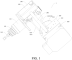
- a brake system 1 according to an embodiment of this application is described below with reference to the accompanying drawings.
- the brake system 1 includes a brake master cylinder assembly 100, a displacement sensor 200, an electro-hydraulic assembly 300, and a control unit 400.
- the brake master cylinder assembly 100 is adapted to connect to a brake pedal 2.
- the displacement sensor 200 is mounted on the brake master cylinder assembly 100 to detect a displacement of a master cylinder piston 120.
- the electro-hydraulic assembly 300 is arranged separately from the brake master cylinder assembly 100 and connected to the brake master cylinder assembly 100 by a connecting oil pipe 60 to implement communication of a brake fluid 101.
- the electro-hydraulic assembly 300 is adapted to connect to a wheel brake 3.
- the control unit 400 is communicatively connected to both the displacement sensor 200 and the electro-hydraulic assembly 300. The control unit 400 controls, according to an action of the brake pedal 2 or a brake command, the electro-hydraulic assembly 300 to output the brake fluid 101 to the wheel brake 3.
- the displacement sensor 200 may detect both a speed and a depth of the brake pedal 2, or the displacement sensor 200 may detect only the depth of the brake pedal 2.
- the brake master cylinder assembly 100 is adapted to connect to the brake pedal 2, and the displacement sensor 200 is mounted on the brake master cylinder assembly 100, to detect the displacement of the master cylinder piston 120 inside the master cylinder assembly 100. That is, the displacement sensor 200 is integrated into the brake master cylinder assembly 100. In this way, the depth of the brake pedal 2 can be measured more accurately, and it is no longer necessary to separately provide a mounting fastener for the displacement sensor 200, which can reduce a quantity of parts and also reduce a mounting space required for both the displacement sensor 200 and the brake master cylinder assembly 100, thereby improving the space utilization.
- the displacement sensor 200 and the brake master cylinder assembly 100 may be disassembled and assembled together, disassembly and assembly steps are reduced, which can improve the disassembly and assembly efficiency.
- the control unit 400 is communicatively connected to the displacement sensor 200.
- the displacement sensor 200 transfers the depth of the brake pedal 2 to the control unit 400.
- the control unit 400 can calculate, according to the depth of the brake pedal 2, a braking force required in a braking process. Because the displacement sensor 200 detects the depth of the brake pedal 2 more accurately, the control unit 400 calculates the braking force more accurately. That is, accurate brake-by-wire can be implemented through higher control accuracy of the control unit 400.
- the electro-hydraulic assembly 300 is arranged separately from the brake master cylinder assembly 100 and connected to the brake master cylinder assembly 100 by a connecting oil pipe 60 to implement communication of the brake fluid 101.
- the electro-hydraulic assembly 300 is adapted to connect to the wheel brake 3.
- the control unit 400 is communicatively connected to the electro-hydraulic assembly 300.
- the control unit 400 controls, according to the action of the brake pedal 2 or the control command, the electro-hydraulic assembly 300 to output the brake fluid 101 to the wheel brake 3. In this way, the control unit 400 can control a fluid volume of the brake fluid 101 output by the electro-hydraulic assembly 300 to the wheel brake 3.
- an automatic driving platform of a vehicle can generate a brake command according to a current road condition, a current vehicle condition, and the like, to form a brake, to adjust a braking force of the wheel brake 3 for a wheel, thereby implementing brakes with different strengths for the vehicle under different conditions, which improves the traveling reliability and extending the service life of the vehicle.
- the electro-hydraulic assembly 300 and the brake master cylinder assembly 100 By arranging the electro-hydraulic assembly 300 and the brake master cylinder assembly 100 separately, the electro-hydraulic assembly 300 and the brake master cylinder assembly 100 have a small and compact structure and a simpler production process, which can reduce the machining difficulty and ensure the quality more easily.
- mounting positions of the electro-hydraulic assembly 300 and the brake master cylinder assembly 100 may also be changed according to actual requirements. Because the mounting positions of the electro-hydraulic assembly 300 and the brake master cylinder assembly 100 do not affect each other, mounting and arrangement are more flexible and have lower requirements for the mounting space.
- the brake master cylinder assembly 100 is connected to the brake pedal 2, and the electro-hydraulic assembly 300 may be arranged at another position.
- Noise conducted to a cab when the electro-hydraulic assembly 300 builds a pressure can be reduced.
- the electro-hydraulic assembly 300 does not need to be adjusted.
- the brake master cylinder assembly 100 has good interchangeability.
- the brake system 1 has advantages such as precise braking force control, easy disassembly and assembly, convenient mounting, and a high space utilization.
- the brake master cylinder assembly 100 includes a master cylinder housing 110, a master cylinder piston 120, and a push rod 140.
- the master cylinder piston 120 is reciprocally arranged inside the master cylinder housing 110 and defines a compression chamber 130 inside the master cylinder housing 110.
- the push rod 140 is connected to the master cylinder piston 120 and adapted to connect to the brake pedal 2.
- the displacement sensor 200 is mounted on the master cylinder housing 110 and is connected to the master cylinder piston 120.
- an accommodating groove 123 is constructed at an end of the master cylinder piston 120 close to the push rod 140.
- An end of the push rod 140 is inserted into the accommodating groove 123, and an other end of the push rod 140 is constructed into a spherical shape, to facilitate connecting to the brake pedal 2.
- a sealing member 141 may be arranged at a joint between the push rod 140 and the master cylinder housing 110, to seal a gap between the push rod 140 and the master cylinder housing 110, thereby preventing dust and the like from entering into the master cylinder housing 110 through the gap between the push rod 140 and the master cylinder housing 110.
- Components of the displacement sensor 200 and the master cylinder piston 120 are placed inside the master cylinder housing 110.
- the components of the displacement sensor 200, the master cylinder piston 120, and the master cylinder housing 110 have a smaller overall volume and can be disassembled and assembled together, which further reduces the disassembly and assembly difficulty of the brake master cylinder assembly 100 and reduces the volume of the brake master cylinder assembly 100.
- the displacement sensor 200 includes a signal generator 210 and a signal receiver 220.
- the signal generator 210 is mounted inside the master cylinder housing 110 and connected to an end of the master cylinder piston 120 adjacent to the push rod 140.
- the signal receiver 220 is mounted outside the master cylinder housing 110 and communicatively connected to the signal generator 210 and the control unit 400.
- an axial direction of the signal receiver 220 may be perpendicular to an extending direction of the master cylinder piston 120.
- the signal generator 210 may move together with the master cylinder piston 120.
- the signal generator 210 can detect a current position of the master cylinder piston 120 more accurately, that is, detect the depth of the brake pedal 2 more accurately.
- there is less obstruction between the signal receiver 220 and the control unit 400 which facilitates communication between the signal receiver 220 and the control unit 400, reduces the probability of interference on the communication between the signal receiver 220 and the control unit 400, and can improve the accuracy of receiving an electrical signal from the signal receiver 220 by the control unit 400.
- the signal receiver 220 and the control unit 400 may be connected by a wire.
- an inner wall of the master cylinder housing 110 is provided with a chute 1101 extending along a movement direction of the master cylinder piston 120, and the signal generator 210 is slidably fitted to the chute 1101.
- the internal space for the master cylinder housing 110 does not need to be too large.
- the structural strength of the master cylinder housing 110 can be ensured, and the sealing between the inner wall of the master cylinder housing 110 and the master cylinder piston 120 can also be ensured, to prevent the compression chamber 130 from failing to normally compress the brake fluid 101.
- the chute 1101 can guide the movement of the signal generator 210, which increases the movement stability of the signal generator 210.
- the signal generator 210 includes a magnetic component 213 and a magnetic component mounting bracket 201.
- the magnetic component mounting bracket 201 includes a radial section 211 and an axial section 212.
- the radial section 211 extends along a radial direction of the master cylinder housing 110 and has one end mounted on the master cylinder piston 120.
- the axial section 212 extends along an axial direction of the master cylinder housing 110 and has one end connected to an other end of the radial section 211. An other end of the axial section 212 is slidably fitted to the chute 1101.
- an outer periphery of the master cylinder piston 120 is sheathed with a mounting ring 150.
- the mounting ring 150 is provided with a ring groove 151 extending along a circumferential direction thereof.
- the one end of the radial section 211 is mounted in the ring groove 151.
- the mounting ring 150 and the master cylinder piston 120 are in interference fit with each other.
- an outer peripheral surface of the master cylinder piston 120 close to an end of the push rod 140 is provided with a positioning groove.
- the mounting ring 150 is located in the positioning groove. An end of the mounting ring 150 abuts against an inner wall of the compression chamber 130, and an other end thereof abuts against a groove wall of the positioning groove.
- the ring groove 151 can fix relative positions of the master cylinder piston 120 and the radial section 211 in an axial direction of the master cylinder piston 120, and the ring groove 151 does not need to be directly machined on the master cylinder piston 120, which can reduce the machining difficulty of the master cylinder piston 120 and can also help replace the mounting ring 150 to adapt to the signal generators 210 of different sizes, thereby improving the applicability of the brake master cylinder assembly 100.
- a depth of the chute 1101 is not less than a maximum movement stroke of the master cylinder piston 120.
- a depth direction of the chute 1101 is the same or parallel to a reciprocating movement direction of the master cylinder piston 120 to ensure that master cylinder piston 120 moves smoothly.
- Such an arrangement can prevent the signal generator 210 from interfering with a bottom wall of the chute 1101 during movement and causing damage to the signal generator 210 or affecting the pedaling depth of the brake pedal 2, thereby reducing the probability of damage to the signal generator 210 and also ensuring that the brake pedal 2 can achieve its maximum displacement.
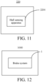
- the signal receiver 220 includes a Hall sensing apparatus 2201.
- the Hall sensing apparatus 2201 is configured to sense a magnetic field strength of the signal generator 210 to detect the action of the brake pedal 2. In this way, the signal generator 210 and the signal receiver 220 do not need to be connected to each other. Therefore, there is no need to reserve structures, such as connecting holes, on the master cylinder housing 110 for the signal generator 210 and the signal receiver 220, thereby ensuring the reliability of signal transfer between the signal generator 210 and signal receiver 220 while increasing the structural strength of the master cylinder housing 110.
- the Hall sensing apparatus 2201 is configured to sense the magnetic field strength of the magnetic component 213.
- the master cylinder piston 120 includes a first master cylinder piston 121 and a second master cylinder piston 122.
- the first master cylinder piston 121 is connected to both the push rod 140 and the displacement sensor 200.
- the second master cylinder piston 122 is located at an end of the first master cylinder piston 121 facing away from the push rod 140.
- the compression chamber 130 includes a first compression chamber 131 and a second compression chamber 132.
- the first compression chamber 131 is formed between the first master cylinder piston 121 and the second master cylinder piston 122
- the second compression chamber 132 is formed between a side of the second master cylinder piston 122 facing away from the first master cylinder piston 121 and the master cylinder housing 110.
- the compression chamber 130 is divided into two parts. While providing the same braking effect for the brake system 1, the first master cylinder piston 121 and the second master cylinder piston 122 are arranged separately, to prevent a single master cylinder piston 120 from being too long, thereby improving the structural strength of the master cylinder piston 120, and avoiding an excessively large volume of a single compression chamber 130, to improve the compression effect on the brake fluid 101, thereby improving the braking efficiency.
- the brake master cylinder assembly 100 further includes a first return spring 160 and a second return spring 170.
- the first return spring 160 is arranged inside the first compression chamber 131 and located between the first master cylinder piston 121 and the second master cylinder piston 122.
- the second return spring 170 is arranged inside the second compression chamber 132 and located between the side of the second master cylinder piston 122 facing away from the first master cylinder piston 121 and the master cylinder housing 110.
- the first return spring 160 can push the first master cylinder piston 121 to return to a non-braking position
- the second return spring 170 can push the second master cylinder piston 122 to return to a non-braking position.
- the first return spring 160 and the second return spring 170 may provide a damping force for the brake pedal 2, so that a driver clearly knows that the brake pedal 2 has been displaced, and the driver can obtain better feedback.
- the brake system 1 further includes an oil pot 180.
- the oil pot 180 is mounted outside the master cylinder housing 110 and is fixedly connected to the master cylinder housing 110.
- the oil pot 180 includes a first opening 181, a second opening 182, and a third opening 183.
- the master cylinder housing 110 is provided with a first oil passage 111 and a second oil passage 112.
- the first oil passage 111 communicates with the first opening 181 and the first compression chamber 131.
- the second oil passage 112 communicates with the second opening 182 and the second compression chamber 132.
- the third opening 183 communicates with the electro-hydraulic assembly 300.
- the third opening 183 and the electro-hydraulic assembly 300 may be connected to each other by an oil supply pipe 380, to avoid the electro-hydraulic assembly 300 from lacking the brake fluid 101 after multiple brakes, thereby improving the reliability of the electro-hydraulic assembly 300.
- the oil pot 180 may supplement the brake fluid 101 to the first compression chamber 131 and the second compression chamber 132 through the first oil passage 111 and the second oil passage 112 respectively. In this way, there is no need to arrange an additional hose structure between the oil pot 180 and the master cylinder housing 110, which simplifies the parts of the brake system 1, lowers costs, and reduces the volume.
- the brake system 1 further includes an oil pot 180.
- the oil pot 180 is arranged separately from the brake master cylinder assembly 100 and includes a first opening 181, a second opening 182, and a third opening 183.
- the oil pot 180 communicates with the brake master cylinder assembly 100 through a first pipeline 184 and a second pipeline 185.
- the first pipeline 184 communicates with the first opening 181 and the first compression chamber 131.
- the second pipeline 185 communicates with the second opening 182 and the second compression chamber 132.
- the third opening 183 communicates with the electro-hydraulic assembly 300.
- the oil pot 180 includes a vehicle large-oil pot 186 and an electro-hydraulic assembly small-oil pot 187.
- a volume of the vehicle large-oil pot 186 is greater than a volume of the electro-hydraulic assembly small-oil pot 187.
- the oil pot 180 for example, the vehicle large-oil pot 186, includes two openings 1861 and 1862.
- An opening 1861 in the two openings 1861 and 1862 is connected to the master cylinder housing 110 by the three-way valve 900 or the three-way pipe 900.
- a port of the three-way valve 900 or the three-way pipe 900 is connected to an opening of the vehicle large-oil pot 186, and the other two ports of the three-way valve 900 or the three-way pipe 900 are connected to the master cylinder housing 110 by the first pipeline 184 and the second pipeline 185 respectively.
- the first pipeline 184 and the second pipeline 185 communicate with the first compression chamber 131 and the second compression chamber 132 respectively.
- the other opening 1862 of the oil pot 180 for example, the vehicle large-oil pot 186, communicates with the electro-hydraulic assembly 300 by the oil supply pipe 380, for example, is connected to the electro-hydraulic assembly small-oil pot 187.
- the vehicle large-oil pot 186 includes a first opening 181, a second opening 182, and a third opening 183.
- the first opening 181 and the second opening 182 are connected to the master cylinder housing 110 respectively.
- the third opening 183 is connected to the electro-hydraulic assembly small-oil pot 187 by the oil supply pipe 380.
- the electro-hydraulic assembly small-oil pot 187 is mounted on the electro-hydraulic assembly 300 and supplements the brake fluid to the electro-hydraulic assembly 300. In this way, when the brake master cylinder assembly 100 needs to be adjusted, the oil pot 180 does not need to be adjusted, and the brake master cylinder assembly 100 has good interchangeability.
- the brake pedal 2 acts synchronously with master cylinder piston 120.
- the displacement of the master cylinder piston 120 detected by the displacement sensor 200 is an actual displacement of the brake pedal 2, which avoids conversion between the displacement of the master cylinder piston 120 and the displacement of the brake pedal 2, leading to simple control logic and convenient calculation.
- a spring and a rubber pad are arranged inside the stroke simulator 500.
- the brake fluid 101 in the first compression chamber 131 flows out and pushes the rubber pad to move.
- the rubber pad drives the spring to compress.
- the spring has a damping force that pushes the rubber pad to move in an opposite direction.
- the damping force acts on the first compression chamber 131 through the rubber pad and the brake fluid 101, to prevent the first compression chamber 131 from continuing to shrink, thereby providing damping for the brake pedal 2 to continue moving downward.
- the damping force can provide the driver with good feedback when the brake pedal 2 is pedaled, which improves the use comfort.
- the electro-hydraulic assembly 300 includes a hydraulic housing 310 and an electric brake assembly 320.
- the control unit 400 and the stroke simulator 500 are mounted on the hydraulic housing 310.
- the electric brake assembly 320 is mounted on the hydraulic housing 310 and includes a pressure chamber 327.
- the pressure chamber 327 is connected to the brake master cylinder assembly 100 and the wheel brake 3.
- the stroke simulator 500 is mounted outside the hydraulic housing 310, to facilitate disassembly and assembly between the electro-hydraulic assembly 300 and the stroke simulator 500.
- stroke simulators 500 with different damping forces can be matched with different vehicle models, which makes applicability higher.
- the stroke simulator 500 is located on a lower side of the hydraulic housing 310. This not only is beneficial to the exhaust of the brake system 1, but also makes mounting and replacement of the brake system 1 more convenient.
- an upper side of the electro-hydraulic assembly 300 can be connected to the brake master cylinder assembly 100.
- the pressure chamber 327 is connected to the third opening 183 by the oil supply pipe 380.
- the electric brake assembly 320 includes a brake housing 321, a drive motor 322, a deceleration and torque-increasing apparatus 323, a transmission screw rod 324, a transmission nut 325, and a brake piston 326.
- the brake housing 321 is mounted on the hydraulic housing 310.
- the drive motor 322 is mounted on the hydraulic housing 310.
- the deceleration and torque-increasing apparatus 323 is transmission-connected to the drive motor 322 and is located on the hydraulic housing 310.
- the transmission screw rod 324 is transmission-connected to the deceleration and torque-increasing apparatus 323.
- the transmission nut 325 is threadedly connected to the transmission screw rod 324.
- the brake piston 326 is mounted inside the brake housing 321 and connected to the transmission nut 325.
- the brake piston 326 and the brake housing 321 form the pressure chamber 327.
- the deceleration and torque-increasing apparatus 323 may be a planetary gear structure. That is, the deceleration and torque-increasing apparatus 323 includes a sun gear 330, a ring gear 360, and multiple planetary gears 340. Each planetary gear 340 is meshed with both the sun gear 330 and the ring gear 360. The multiple planetary gears 340 surround the sun gear 330 along a circumferential direction of the sun gear 330. The ring gear 360 is sleeved over the sun gear 330. An output shaft of the drive motor 322 may be connected to the sun gear 330.
- the multiple planetary gears 340 are connected to the transmission screw rod 324 by a planetary gear shaft 350.
- the planetary gear shaft 350 is connected to all the multiple planetary gears 340. That is, the multiple planetary gears 340 jointly drive the planetary gear shaft 350 to move.
- An output rotation speed of the planetary gear shaft 350 of the deceleration and torque-increasing apparatus 323 is lower than an input rotation speed of the sun gear 330, and an output torque of the planetary gear shaft 350 of the deceleration and torque-increasing apparatus 323 is less than an input torque of the sun gear 330, to achieve the deceleration and torque-increasing effects.
- rotational movement of the drive motor 322 can be converted into linear movement to drive the brake piston 326 to move in the brake housing 321, to change the volume of the pressure chamber 327, thereby implementing braking and normal traveling of the vehicle.
- a moving direction of the brake piston 326 may be parallel to an axial direction of the drive motor 322.
- control unit 400 and the drive motor 322 may be located on two opposite sides of the hydraulic housing 310.
- the transmission nut 325 and the brake piston 326 are fixed together in a rotationally fixed manner, and the transmission screw rod 324 and the planetary gear shaft 350 may be in interference fit with each other.
- a bearing 370 may be mounted on the transmission screw rod 324 and the hydraulic housing 310 to implement relative rotation between the transmission screw rod 324 and the hydraulic housing 310, and can fix relative positions between the transmission screw rod 324 and the hydraulic housing 310 in the axial direction and the radial direction of the transmission screw rod 324.
- the brake system 1 further includes a brake fluid shut-off valve 600.
- the brake master cylinder assembly 100 is connected to the wheel brake 3 by the brake fluid shut-off valve 600.
- the brake fluid shut-off valve 600 is configured to control transmission of the brake fluid between the brake master cylinder assembly 100 and the wheel brake 3. For example, when being powered on, the brake fluid shut-off valve 600 is in a closed state to prevent the brake master cylinder assembly 100 from transmitting the brake fluid 101 to the wheel brake 3, and when being powered off, the brake fluid shut-off valve 600 is in an open state to allow the brake master cylinder assembly 100 to transmit the brake fluid 101 to the wheel brake 3.
- the brake fluid shut-off valve 600 may be a solenoid valve.
- the solenoid valve and the drive motor 322 are located on two opposite sides of the hydraulic housing 310.
- the brake fluid shut-off valve 600 is embedded in the hydraulic housing 310 and is sealed by riveting.
- the control unit 400 can control opening and closing of the brake fluid shut-off valve 600.
- the control unit 400 controls the brake fluid shut-off valve 600 to be in a closed state.
- the vehicle can be accurately braked through only the electric brake assembly 320.
- the control unit 400 cannot control the brake fluid shut-off valve 600 to be in a closed state, and the brake fluid shut-off valve 600 changes from the closed state to an open state.
- the brake pedal 2 is pedaled, the brake fluid 101 directly enters the wheel brake 3 to brake the vehicle.
- the vehicle can be braked in both cases, that is, normal traveling and power-off traveling, which makes the traveling of the vehicle safer.
- a solenoid valve may further be arranged between the brake pedal 2 and the first compression chamber 131.
- the solenoid valve is in a closed state during power-off and is in an open state during power-on.
- the stroke simulator 500 provides a damping force for the brake pedal 2 when the brake pedal 2 is pedaled.
- the stroke simulator 500 may not provide a damping force for the brake pedal 2, to enable the driver to pedal the brake pedal 2 to the maximum stroke, to implement parking when the vehicle is in a power-off state.
- the brake fluid 101 in each wheel brake 3 may be connected to the oil pot 180 by the pressure reducing valve 800 connected thereto.
- the connecting oil pipe 60 includes a first connecting oil pipe 610 and a second connecting oil pipe 620.
- a brake fluid shut-off valve 600 is connected to the second compression chamber 132 by the second connecting oil pipe 620.
- An other brake fluid shut-off valve 600 may be connected to the first compression chamber 131 by the first connecting oil pipe 610.
- the brake fluid shut-off valve 600 When the brake system 1 is powered on, the brake fluid shut-off valve 600 is closed. When the user pedals the brake pedal 2, the first master cylinder piston 121 and the second master cylinder piston 122 move. Spaces of the first compression chamber 131 and the second compression chamber 132 are reduced. The brake fluid 101 of the first compression chamber 131 flows to the stroke simulator 500 through the first connecting oil pipe 610, to provide foot feel simulation for the brake pedal 2. Moreover, the drive motor 322 rotates to reduce the space of the pressure chamber 327, and the brake fluid 101 in the pressure chamber 327 flows to the wheel brakes 3 through the four pressure maintaining valves 700, to brake the wheels.
- the brake fluid shut-off valve 600 When the brake system 1 is powered off, the brake fluid shut-off valve 600 is open. When the user pedals the brake pedal 2, the first master cylinder piston 121 and the second master cylinder piston 122 move. Spaces of the first compression chamber 131 and the second compression chamber 132 are reduced. The brake fluid 101 of the first compression chamber 131 and the second compression chamber 132 flows to the brake fluid shut-off valve 600 through the first connecting oil pipe 610 and the second connecting oil pipe 620, and then flows to the wheel brakes 3 through the pressure maintaining valves 700, to brake the wheels.
- the vehicle 1000 includes the brake system 1 according to the foregoing embodiments of the present disclosure.
- the vehicle 1000 may be a passenger car.
- the brake master cylinder assembly 100 may be mounted on an engine compartment of the passenger car near a front wall panel.
- the vehicle 1000 may be a light commercial vehicle.
- the brake master cylinder assembly 100 may be mounted inside a cab of the light commercial vehicle.
- a distance between the electro-hydraulic assembly 300 and a driver may be greater than a distance between the brake master cylinder assembly 100 and the driver. In this way, it is difficult for noise of the electro-hydraulic assembly 300 during operation to be transferred to a position of the driver, thereby improving the noise, vibration, and harshness (NVH) effect.
- the vehicle 1000 By utilizing the brake system 1 according to the foregoing embodiments of the present disclosure, the vehicle 1000 according to this embodiment of the present disclosure has advantages such as precise braking force control, easy disassembly and assembly, convenient mounting, and a high space utilization.
Landscapes
- Engineering & Computer Science (AREA)
- Transportation (AREA)
- Mechanical Engineering (AREA)
- Physics & Mathematics (AREA)
- Fluid Mechanics (AREA)
- Electromagnetism (AREA)
- Transmission Of Braking Force In Braking Systems (AREA)
- Braking Systems And Boosters (AREA)
- Braking Elements And Transmission Devices (AREA)
- Regulating Braking Force (AREA)
- Braking Arrangements (AREA)
- Valves And Accessory Devices For Braking Systems (AREA)
Abstract
Description
- The present disclosure claims priority to and benefits of
Chinese Patent Application No. 202111317737.2, filed on November 9, 2021 - The present disclosure relates to the field of vehicle technologies, and more specifically, to a brake system and a vehicle including same.
- A brake system in the related art is usually a combination of a vacuum booster master cylinder and an antilock brake system (ABS) module. The vacuum booster master cylinder has a large volume, occupies a lot of space, is complex to repair and replace, and further, requires arrangement of a vacuum pump. Moreover, there is no displacement sensor in the combination of the vacuum booster master cylinder and the ABS module. As a result, brake-by-wire cannot be implemented, and the control accuracy of a braking force is low
- The present disclosure is intended to resolve at least one of the technical problems existing in the related art. To this end, an objective of the present disclosure is to provide a brake system. The brake system has advantages such as precise braking force control, easy disassembly and assembly, convenient mounting, and a high space utilization.
- The present disclosure further provides a vehicle including the foregoing brake system.
- To achieve the foregoing objective, according to an embodiment of first aspect of the present disclosure, a brake system is provided, including: a brake master cylinder assembly, a displacement sensor, an electro-hydraulic assembly, and a control unit. The brake master cylinder assembly is adapted to connect to a brake pedal. The brake master cylinder assembly includes a master cylinder housing and a master cylinder piston. The master cylinder piston is reciprocally arranged inside the master cylinder housing and defines a compression chamber inside the master cylinder housing. The displacement sensor is mounted on the brake master cylinder assembly to detect a displacement of the master cylinder piston. The electro-hydraulic assembly is arranged separately from the brake master cylinder assembly and connected to the brake master cylinder assembly by a connecting oil pipe to implement communication of a brake fluid. The electro-hydraulic assembly is adapted to connect to a wheel brake. The control unit is communicatively connected to both the displacement sensor and the electro-hydraulic assembly. The control unit controls, according to an action of the brake pedal or a brake command, the electro-hydraulic assembly to output the brake fluid to the wheel brake.
- The brake system according to this embodiment of the present disclosure has advantages such as precise braking force control, easy disassembly and assembly, convenient mounting, and a high space utilization.
- According to some embodiments of the present disclosure, the brake master cylinder assembly further includes a push rod. The push rod is connected to the master cylinder piston and adapted to connect to the brake pedal. The displacement sensor is mounted on the master cylinder housing and is connected to the master cylinder piston.
- According to some embodiments of the present disclosure, the displacement sensor includes a signal generator and a signal receiver. The signal generator is mounted inside the master cylinder housing and connected to an end of the master cylinder piston adjacent to the push rod. The signal receiver is mounted outside the master cylinder housing and communicatively connected to both the signal generator and the control unit.
- According to some embodiments of the present disclosure, an inner wall of the master cylinder housing is provided with a chute extending along a movement direction of the master cylinder piston. The signal generator is slidably fitted to the chute.
- According to some embodiments of the present disclosure, the signal generator includes a magnetic component and a magnetic component mounting bracket. The magnetic component mounting bracket includes a radial section and an axial section. The radial section extends along a radial direction of the master cylinder housing and has one end mounted on the master cylinder piston. The axial section extends along an axial direction of the master cylinder housing and has one end connected to an other end of the radial section. An other end of the axial section is slidably fitted to the chute.
- According to some embodiments of the present disclosure, an outer periphery of the master cylinder piston is sheathed with a mounting ring. The mounting ring is provided with a ring groove extending along a circumferential direction thereof. The one end of the radial section is mounted in the ring groove.
- According to some embodiments of the present disclosure, a depth of the chute is not less than a maximum movement stroke of the master cylinder piston. A depth direction of the chute is the same as or parallel to a reciprocating movement direction of the master cylinder piston.
- According to some embodiments of the present disclosure, the signal receiver includes a Hall sensing apparatus. The Hall sensing apparatus is configured to sense a magnetic field strength of the signal generator to detect the action of the brake pedal.
- According to some embodiments of the present disclosure, the master cylinder piston includes a first master cylinder piston and a second master cylinder piston. The first master cylinder piston is connected to both the push rod and the displacement sensor. The second master cylinder piston is located at an end of the first master cylinder piston facing away from the push rod. The compression chamber includes a first compression chamber and a second compression chamber. The first compression chamber is formed between the first master cylinder piston and the second master cylinder piston. The second compression chamber is formed between a side of the second master cylinder piston facing away from the first master cylinder piston and the master cylinder housing.
- According to some embodiments of the present disclosure, the brake master cylinder assembly further includes a first return spring and a second return spring. The first return spring is arranged inside the first compression chamber and located between the first master cylinder piston and the second master cylinder piston. The second return spring is arranged inside the second compression chamber and located between the side of the second master cylinder piston facing away from the first master cylinder piston and the master cylinder housing.
- According to some embodiments of the present disclosure, the brake system further includes an oil pot. The oil pot is mounted outside the master cylinder housing and fixedly connected to the master cylinder housing. The oil pot includes a first opening, a second opening, and a third opening. The master cylinder housing is provided with a first oil passage and a second oil passage. The first oil passage communicates with the first opening and the first compression chamber. The second oil passage communicates with the second opening and the second compression chamber. The third opening communicates with the electro-hydraulic assembly.
- According to some embodiments of the present disclosure, the brake system further includes an oil pot. The oil pot is arranged separately from the brake master cylinder assembly and includes a first opening, a second opening, and a third opening. The oil pot communicates with the brake master cylinder assembly through a first pipeline and a second pipeline. The first pipeline communicates with the first opening and the first compression chamber. The second pipeline communicates with the second opening and the second compression chamber. The third opening communicates with the electro-hydraulic assembly.
- According to some embodiments of the present disclosure, the brake system further includes an oil pot. The oil pot is arranged separately from the brake master cylinder assembly and includes two openings. An opening of the oil pot communicates with a three-way valve or a three-way pipe. The three-way valve or the three-way pipe communicates with the brake master cylinder assembly through a first pipeline and a second pipeline. The first pipeline and the second pipeline communicate with the first compression chamber and the second compression chamber respectively. The other opening of the oil pot communicates with the electro-hydraulic assembly.
- According to some embodiments of the present disclosure, the brake pedal acts synchronously with the master cylinder piston.
- According to some embodiments of the present disclosure, the brake system further includes a stroke simulator. The stroke simulator is mounted on the electro-hydraulic assembly. The stroke simulator is connected to the brake master cylinder assembly to implement communication of the brake fluid. By applying a return pressure to the brake fluid delivered to the brake master cylinder assembly, the stroke simulator provides the brake pedal with a damping force that increases with a pedaling depth.
- According to some embodiments of the present disclosure, the electro-hydraulic assembly includes a hydraulic housing and an electric brake assembly The control unit and the stroke simulator are mounted on the hydraulic housing. The electric brake assembly is mounted on the hydraulic housing and includes a pressure chamber. The pressure chamber is connected to the brake master cylinder assembly and the wheel brake respectively.
- According to some embodiments of the present disclosure, the stroke simulator is located on a lower side of the hydraulic housing.
- According to some embodiments of the present disclosure, the electric brake assembly includes a brake housing, a drive motor, a deceleration and torque-increasing apparatus, a transmission screw rod, a transmission nut, and a brake piston. The brake housing is mounted on the hydraulic housing. The drive motor is mounted on the hydraulic housing. The deceleration and torque-increasing apparatus is transmission-connected to the drive motor and arranged on the hydraulic housing. The transmission screw rod is transmission-connected to the deceleration and torque-increasing apparatus. The transmission nut is threadedly connected to the transmission screw rod. The brake piston is mounted inside the brake housing and connected to the transmission nut. The brake piston and the brake housing form the pressure chamber.
- According to some embodiments of the present disclosure, the brake system further includes a brake fluid shut-off valve. The brake master cylinder assembly is connected to the wheel brake by the brake fluid shut-off valve. The brake fluid shut-off valve is configured to control transmission of the brake fluid between the brake master cylinder assembly and the wheel brake.
- According to an embodiment of a second aspect of the present disclosure, a vehicle is provided, including the brake system according to the embodiment of the first aspect of the present disclosure.
- By utilizing the brake system according to the embodiment of the first aspect of the present disclosure, the vehicle according to the embodiment of the second aspect of the present disclosure has advantages such as precise braking force control, easy disassembly and assembly, convenient mounting, and a high space utilization.
- Additional aspects and advantages of the present disclosure are partially provided in the following description, and partially become apparent in the following description or understood through the practice of the present disclosure.
- The foregoing and/or additional aspects and advantages of this application become apparent and comprehensible in the description made with reference to the following accompanying drawing.
-
FIG. 1 is a schematic structural diagram of a brake system according to an embodiment of the present disclosure; -
FIG. 2 is a schematic structural diagram of a brake system according to an embodiment of the present disclosure from another perspective; -
FIG. 3 is a schematic structural diagram of a brake system according to an embodiment of the present disclosure from still another perspective; -
FIG. 4 is a schematic structural diagram of a brake system according to another embodiment of the present disclosure; -
FIG. 5 is a cross-sectional view of a brake master cylinder assembly of a brake system according to an embodiment of the present disclosure; -
FIG. 6 is another cross-sectional view of a brake master cylinder assembly of a brake system according to an embodiment of the present disclosure; -
FIG. 7 is a schematic structural diagram of an electro-hydraulic assembly of a brake system according to an embodiment of the present disclosure; -
FIG. 8 is a cross-sectional view of an electro-hydraulic assembly of a brake system according to an embodiment of the present disclosure; -
FIG. 9 is a schematic diagram of flowing of a brake fluid of a brake system according to an embodiment of the present disclosure; -
FIG. 10 is another schematic diagram of flowing of a brake fluid of a brake system according to an embodiment of the present disclosure; -
FIG. 11 is a schematic block diagram of a signal receiver according to an embodiment of the present disclosure; and -
FIG. 12 is a schematic block diagram of a vehicle according to an embodiment of the present disclosure. -
Brake system 1,brake pedal 2,wheel brake 3, - brake
master cylinder assembly 100,brake fluid 101,master cylinder housing 110,first oil passage 111,second oil passage 112,master cylinder piston 120, firstmaster cylinder piston 121, secondmaster cylinder piston 122,accommodating groove 123,compression chamber 130,first compression chamber 131,second compression chamber 132,push rod 140, sealingmember 141, mountingring 150,ring groove 151,first return spring 160,second return spring 170,oil pot 180,first opening 181,second opening 182,third opening 183,first pipeline 184,second pipeline 185, vehicle large-oil pot 186, electro-hydraulic assembly small-oil pot 187,chute 1101, opening 1861, 1862, -
displacement sensor 200,signal generator 210, magnetic component mounting bracket 201,radial section 211,axial section 212,magnetic component 213,signal receiver 220,Hall sensing apparatus 2201, - electro-
hydraulic assembly 300,hydraulic housing 310,electric brake assembly 320,brake housing 321, drivemotor 322, deceleration and torque-increasingapparatus 323,transmission screw rod 324,transmission nut 325,brake piston 326,pressure chamber 327,sun gear 330,planetary gear 340,planetary gear shaft 350,ring gear 360, bearing 370, oil supply pipe (380) 380, -
control unit 400,stroke simulator 500, brake fluid shut-offvalve 600, first connectingoil pipe 610, second connectingoil pipe 620,pressure maintaining valve 700,pressure reducing valve 800, three-way valve or three-way pipe 900;vehicle 1000. - The embodiments of the present disclosure are described below in detail, and the embodiments described with reference to accompanying drawings are exemplary.
- In the description of the present disclosure, it should be understood that, orientations or position relationships indicated by terms such as "center", "longitudinal", "transverse", "length", "width", "thickness", "up", "down", "front", "back", "left", "right", "vertical", "horizontal", "top", "bottom", "inner", "outer", "clockwise", "counterclockwise", "axial", "radial", and "circumferential" are orientations or position relationship shown based on the accompanying drawings, and are merely used for describing the present disclosure and simplifying the description, rather than indicating or implying that the apparatus or element should have a particular orientation or be constructed and operated in a particular orientation, and therefore, should not be construed as a limitation on the present disclosure.
- In the description of the present disclosure, "multiple" means two or more.
- A
brake system 1 according to an embodiment of this application is described below with reference to the accompanying drawings. - As shown in
FIG. 1 to FIG. 11 , thebrake system 1 includes a brakemaster cylinder assembly 100, adisplacement sensor 200, an electro-hydraulic assembly 300, and acontrol unit 400. - The brake
master cylinder assembly 100 is adapted to connect to abrake pedal 2. Thedisplacement sensor 200 is mounted on the brakemaster cylinder assembly 100 to detect a displacement of amaster cylinder piston 120. The electro-hydraulic assembly 300 is arranged separately from the brakemaster cylinder assembly 100 and connected to the brakemaster cylinder assembly 100 by a connectingoil pipe 60 to implement communication of abrake fluid 101. The electro-hydraulic assembly 300 is adapted to connect to awheel brake 3. Thecontrol unit 400 is communicatively connected to both thedisplacement sensor 200 and the electro-hydraulic assembly 300. Thecontrol unit 400 controls, according to an action of thebrake pedal 2 or a brake command, the electro-hydraulic assembly 300 to output thebrake fluid 101 to thewheel brake 3. - The
displacement sensor 200 may detect both a speed and a depth of thebrake pedal 2, or thedisplacement sensor 200 may detect only the depth of thebrake pedal 2. - For the
brake system 1 according to this embodiment of the present disclosure, the brakemaster cylinder assembly 100 is adapted to connect to thebrake pedal 2, and thedisplacement sensor 200 is mounted on the brakemaster cylinder assembly 100, to detect the displacement of themaster cylinder piston 120 inside themaster cylinder assembly 100. That is, thedisplacement sensor 200 is integrated into the brakemaster cylinder assembly 100. In this way, the depth of thebrake pedal 2 can be measured more accurately, and it is no longer necessary to separately provide a mounting fastener for thedisplacement sensor 200, which can reduce a quantity of parts and also reduce a mounting space required for both thedisplacement sensor 200 and the brakemaster cylinder assembly 100, thereby improving the space utilization. In addition, because thedisplacement sensor 200 and the brakemaster cylinder assembly 100 may be disassembled and assembled together, disassembly and assembly steps are reduced, which can improve the disassembly and assembly efficiency. - The
control unit 400 is communicatively connected to thedisplacement sensor 200. Thedisplacement sensor 200 transfers the depth of thebrake pedal 2 to thecontrol unit 400. Thecontrol unit 400 can calculate, according to the depth of thebrake pedal 2, a braking force required in a braking process. Because thedisplacement sensor 200 detects the depth of thebrake pedal 2 more accurately, thecontrol unit 400 calculates the braking force more accurately. That is, accurate brake-by-wire can be implemented through higher control accuracy of thecontrol unit 400. - In addition, the electro-
hydraulic assembly 300 is arranged separately from the brakemaster cylinder assembly 100 and connected to the brakemaster cylinder assembly 100 by a connectingoil pipe 60 to implement communication of thebrake fluid 101. The electro-hydraulic assembly 300 is adapted to connect to thewheel brake 3. Thecontrol unit 400 is communicatively connected to the electro-hydraulic assembly 300. Thecontrol unit 400 controls, according to the action of thebrake pedal 2 or the control command, the electro-hydraulic assembly 300 to output thebrake fluid 101 to thewheel brake 3. In this way, thecontrol unit 400 can control a fluid volume of thebrake fluid 101 output by the electro-hydraulic assembly 300 to thewheel brake 3. In addition, when thebrake system 1 is used in automatic driving, an automatic driving platform of a vehicle can generate a brake command according to a current road condition, a current vehicle condition, and the like, to form a brake, to adjust a braking force of thewheel brake 3 for a wheel, thereby implementing brakes with different strengths for the vehicle under different conditions, which improves the traveling reliability and extending the service life of the vehicle. - By arranging the electro-
hydraulic assembly 300 and the brakemaster cylinder assembly 100 separately, the electro-hydraulic assembly 300 and the brakemaster cylinder assembly 100 have a small and compact structure and a simpler production process, which can reduce the machining difficulty and ensure the quality more easily. In addition, mounting positions of the electro-hydraulic assembly 300 and the brakemaster cylinder assembly 100 may also be changed according to actual requirements. Because the mounting positions of the electro-hydraulic assembly 300 and the brakemaster cylinder assembly 100 do not affect each other, mounting and arrangement are more flexible and have lower requirements for the mounting space. For example, the brakemaster cylinder assembly 100 is connected to thebrake pedal 2, and the electro-hydraulic assembly 300 may be arranged at another position. Noise conducted to a cab when the electro-hydraulic assembly 300 builds a pressure can be reduced. Moreover, when the brakemaster cylinder assembly 100 needs to be adjusted, the electro-hydraulic assembly 300 does not need to be adjusted. The brakemaster cylinder assembly 100 has good interchangeability. - In this way, the
brake system 1 according to this embodiment of the present disclosure has advantages such as precise braking force control, easy disassembly and assembly, convenient mounting, and a high space utilization. - According to some specific embodiments of the present disclosure, as shown in
FIG. 1 to FIG. 3 andFIG. 5 , the brakemaster cylinder assembly 100 includes amaster cylinder housing 110, amaster cylinder piston 120, and apush rod 140. - The
master cylinder piston 120 is reciprocally arranged inside themaster cylinder housing 110 and defines acompression chamber 130 inside themaster cylinder housing 110. Thepush rod 140 is connected to themaster cylinder piston 120 and adapted to connect to thebrake pedal 2. Thedisplacement sensor 200 is mounted on themaster cylinder housing 110 and is connected to themaster cylinder piston 120. - For example, an
accommodating groove 123 is constructed at an end of themaster cylinder piston 120 close to thepush rod 140. An end of thepush rod 140 is inserted into theaccommodating groove 123, and an other end of thepush rod 140 is constructed into a spherical shape, to facilitate connecting to thebrake pedal 2. Moreover, a sealingmember 141 may be arranged at a joint between thepush rod 140 and themaster cylinder housing 110, to seal a gap between thepush rod 140 and themaster cylinder housing 110, thereby preventing dust and the like from entering into themaster cylinder housing 110 through the gap between thepush rod 140 and themaster cylinder housing 110. - Components of the
displacement sensor 200 and themaster cylinder piston 120 are placed inside themaster cylinder housing 110. In this way, the components of thedisplacement sensor 200, themaster cylinder piston 120, and themaster cylinder housing 110 have a smaller overall volume and can be disassembled and assembled together, which further reduces the disassembly and assembly difficulty of the brakemaster cylinder assembly 100 and reduces the volume of the brakemaster cylinder assembly 100. - According to some specific embodiments of the present disclosure, as shown in
FIG. 2 to FIG. 5 , thedisplacement sensor 200 includes asignal generator 210 and asignal receiver 220. Thesignal generator 210 is mounted inside themaster cylinder housing 110 and connected to an end of themaster cylinder piston 120 adjacent to thepush rod 140. Thesignal receiver 220 is mounted outside themaster cylinder housing 110 and communicatively connected to thesignal generator 210 and thecontrol unit 400. - For example, an axial direction of the
signal receiver 220 may be perpendicular to an extending direction of themaster cylinder piston 120. In this way, thesignal generator 210 may move together with themaster cylinder piston 120. Thesignal generator 210 can detect a current position of themaster cylinder piston 120 more accurately, that is, detect the depth of thebrake pedal 2 more accurately. Moreover, there is less obstruction between thesignal receiver 220 and thecontrol unit 400, which facilitates communication between thesignal receiver 220 and thecontrol unit 400, reduces the probability of interference on the communication between thesignal receiver 220 and thecontrol unit 400, and can improve the accuracy of receiving an electrical signal from thesignal receiver 220 by thecontrol unit 400. Thesignal receiver 220 and thecontrol unit 400 may be connected by a wire. - Further, an inner wall of the
master cylinder housing 110 is provided with achute 1101 extending along a movement direction of themaster cylinder piston 120, and thesignal generator 210 is slidably fitted to thechute 1101. In this way, not only interference between the inner wall of themaster cylinder housing 110 and thesignal generator 210 can be avoided, but also the internal space for themaster cylinder housing 110 does not need to be too large. The structural strength of themaster cylinder housing 110 can be ensured, and the sealing between the inner wall of themaster cylinder housing 110 and themaster cylinder piston 120 can also be ensured, to prevent thecompression chamber 130 from failing to normally compress thebrake fluid 101. Moreover, thechute 1101 can guide the movement of thesignal generator 210, which increases the movement stability of thesignal generator 210. - Specifically, as shown in
FIG. 5 , thesignal generator 210 includes amagnetic component 213 and a magnetic component mounting bracket 201. The magnetic component mounting bracket 201 includes aradial section 211 and anaxial section 212. Theradial section 211 extends along a radial direction of themaster cylinder housing 110 and has one end mounted on themaster cylinder piston 120. Theaxial section 212 extends along an axial direction of themaster cylinder housing 110 and has one end connected to an other end of theradial section 211. An other end of theaxial section 212 is slidably fitted to thechute 1101. - There may be an arc transition between the
radial section 211 and theaxial section 212, to avoid stress concentration between theradial section 211 and theaxial section 212. In this way, not only the fixation between thesignal generator 210 and themaster cylinder piston 120 can be achieved, but also that the moving direction of thesignal generator 210 is parallel to the moving direction of themaster cylinder piston 120 can be ensured, thereby improving the accuracy of detection on the depth of thebrake pedal 2. - Optionally, an outer periphery of the
master cylinder piston 120 is sheathed with a mountingring 150. The mountingring 150 is provided with aring groove 151 extending along a circumferential direction thereof. The one end of theradial section 211 is mounted in thering groove 151. The mountingring 150 and themaster cylinder piston 120 are in interference fit with each other. For example, an outer peripheral surface of themaster cylinder piston 120 close to an end of thepush rod 140 is provided with a positioning groove. The mountingring 150 is located in the positioning groove. An end of the mountingring 150 abuts against an inner wall of thecompression chamber 130, and an other end thereof abuts against a groove wall of the positioning groove. - In this way, the
ring groove 151 can fix relative positions of themaster cylinder piston 120 and theradial section 211 in an axial direction of themaster cylinder piston 120, and thering groove 151 does not need to be directly machined on themaster cylinder piston 120, which can reduce the machining difficulty of themaster cylinder piston 120 and can also help replace the mountingring 150 to adapt to thesignal generators 210 of different sizes, thereby improving the applicability of the brakemaster cylinder assembly 100. - In some embodiments of the present disclosure, a depth of the
chute 1101 is not less than a maximum movement stroke of themaster cylinder piston 120. A depth direction of thechute 1101 is the same or parallel to a reciprocating movement direction of themaster cylinder piston 120 to ensure thatmaster cylinder piston 120 moves smoothly. Such an arrangement can prevent thesignal generator 210 from interfering with a bottom wall of thechute 1101 during movement and causing damage to thesignal generator 210 or affecting the pedaling depth of thebrake pedal 2, thereby reducing the probability of damage to thesignal generator 210 and also ensuring that thebrake pedal 2 can achieve its maximum displacement. - According to some specific embodiments of the present disclosure, the
signal receiver 220 includes aHall sensing apparatus 2201. TheHall sensing apparatus 2201 is configured to sense a magnetic field strength of thesignal generator 210 to detect the action of thebrake pedal 2. In this way, thesignal generator 210 and thesignal receiver 220 do not need to be connected to each other. Therefore, there is no need to reserve structures, such as connecting holes, on themaster cylinder housing 110 for thesignal generator 210 and thesignal receiver 220, thereby ensuring the reliability of signal transfer between thesignal generator 210 andsignal receiver 220 while increasing the structural strength of themaster cylinder housing 110. - Further, the
Hall sensing apparatus 2201 is configured to sense the magnetic field strength of themagnetic component 213. - According to some specific embodiments of the present disclosure, as shown in
FIG. 5 to FIG. 11 , themaster cylinder piston 120 includes a firstmaster cylinder piston 121 and a secondmaster cylinder piston 122. The firstmaster cylinder piston 121 is connected to both thepush rod 140 and thedisplacement sensor 200. The secondmaster cylinder piston 122 is located at an end of the firstmaster cylinder piston 121 facing away from thepush rod 140. Thecompression chamber 130 includes afirst compression chamber 131 and asecond compression chamber 132. Thefirst compression chamber 131 is formed between the firstmaster cylinder piston 121 and the secondmaster cylinder piston 122, and thesecond compression chamber 132 is formed between a side of the secondmaster cylinder piston 122 facing away from the firstmaster cylinder piston 121 and themaster cylinder housing 110. - In this way, the
compression chamber 130 is divided into two parts. While providing the same braking effect for thebrake system 1, the firstmaster cylinder piston 121 and the secondmaster cylinder piston 122 are arranged separately, to prevent a singlemaster cylinder piston 120 from being too long, thereby improving the structural strength of themaster cylinder piston 120, and avoiding an excessively large volume of asingle compression chamber 130, to improve the compression effect on thebrake fluid 101, thereby improving the braking efficiency. - Further, as shown in
FIG. 5 , the brakemaster cylinder assembly 100 further includes afirst return spring 160 and asecond return spring 170. Thefirst return spring 160 is arranged inside thefirst compression chamber 131 and located between the firstmaster cylinder piston 121 and the secondmaster cylinder piston 122. Thesecond return spring 170 is arranged inside thesecond compression chamber 132 and located between the side of the secondmaster cylinder piston 122 facing away from the firstmaster cylinder piston 121 and themaster cylinder housing 110. - Through such an arrangement, the
first return spring 160 can push the firstmaster cylinder piston 121 to return to a non-braking position, and thesecond return spring 170 can push the secondmaster cylinder piston 122 to return to a non-braking position. In this way, next use of thebrake pedal 2 is facilitated, and whenbrake pedal 2 is pedaled, thefirst return spring 160 and thesecond return spring 170 may provide a damping force for thebrake pedal 2, so that a driver clearly knows that thebrake pedal 2 has been displaced, and the driver can obtain better feedback. - In some embodiments of the present disclosure, as shown in
FIG. 5 , thebrake system 1 further includes anoil pot 180. Theoil pot 180 is mounted outside themaster cylinder housing 110 and is fixedly connected to themaster cylinder housing 110. Theoil pot 180 includes afirst opening 181, asecond opening 182, and athird opening 183. Themaster cylinder housing 110 is provided with afirst oil passage 111 and asecond oil passage 112. Thefirst oil passage 111 communicates with thefirst opening 181 and thefirst compression chamber 131. Thesecond oil passage 112 communicates with thesecond opening 182 and thesecond compression chamber 132. Thethird opening 183 communicates with the electro-hydraulic assembly 300. - For example, with reference to
FIG. 1 andFIG. 5 toFIG. 11 , thethird opening 183 and the electro-hydraulic assembly 300 may be connected to each other by anoil supply pipe 380, to avoid the electro-hydraulic assembly 300 from lacking thebrake fluid 101 after multiple brakes, thereby improving the reliability of the electro-hydraulic assembly 300. Moreover, theoil pot 180 may supplement thebrake fluid 101 to thefirst compression chamber 131 and thesecond compression chamber 132 through thefirst oil passage 111 and thesecond oil passage 112 respectively. In this way, there is no need to arrange an additional hose structure between theoil pot 180 and themaster cylinder housing 110, which simplifies the parts of thebrake system 1, lowers costs, and reduces the volume. - In some other embodiments of the present disclosure, as shown in
FIG. 4 , thebrake system 1 further includes anoil pot 180. Theoil pot 180 is arranged separately from the brakemaster cylinder assembly 100 and includes afirst opening 181, asecond opening 182, and athird opening 183. Theoil pot 180 communicates with the brakemaster cylinder assembly 100 through afirst pipeline 184 and asecond pipeline 185. Thefirst pipeline 184 communicates with thefirst opening 181 and thefirst compression chamber 131. Thesecond pipeline 185 communicates with thesecond opening 182 and thesecond compression chamber 132. Thethird opening 183 communicates with the electro-hydraulic assembly 300. - For example, the
oil pot 180 includes a vehicle large-oil pot 186 and an electro-hydraulic assembly small-oil pot 187. A volume of the vehicle large-oil pot 186 is greater than a volume of the electro-hydraulic assembly small-oil pot 187. - In an embodiment, with reference to
FIG. 10 , theoil pot 180, for example, the vehicle large-oil pot 186, includes twoopenings opening 1861 in the twoopenings master cylinder housing 110 by the three-way valve 900 or the three-way pipe 900. Specifically, a port of the three-way valve 900 or the three-way pipe 900 is connected to an opening of the vehicle large-oil pot 186, and the other two ports of the three-way valve 900 or the three-way pipe 900 are connected to themaster cylinder housing 110 by thefirst pipeline 184 and thesecond pipeline 185 respectively. Thefirst pipeline 184 and thesecond pipeline 185 communicate with thefirst compression chamber 131 and thesecond compression chamber 132 respectively. Theother opening 1862 of theoil pot 180, for example, the vehicle large-oil pot 186, communicates with the electro-hydraulic assembly 300 by theoil supply pipe 380, for example, is connected to the electro-hydraulic assembly small-oil pot 187. - In another embodiment, the vehicle large-
oil pot 186 includes afirst opening 181, asecond opening 182, and athird opening 183. Thefirst opening 181 and thesecond opening 182 are connected to themaster cylinder housing 110 respectively. Thethird opening 183 is connected to the electro-hydraulic assembly small-oil pot 187 by theoil supply pipe 380. The electro-hydraulic assembly small-oil pot 187 is mounted on the electro-hydraulic assembly 300 and supplements the brake fluid to the electro-hydraulic assembly 300. In this way, when the brakemaster cylinder assembly 100 needs to be adjusted, theoil pot 180 does not need to be adjusted, and the brakemaster cylinder assembly 100 has good interchangeability. - According to some specific embodiments of the present disclosure, the
brake pedal 2 acts synchronously withmaster cylinder piston 120. In this way, the displacement of themaster cylinder piston 120 detected by thedisplacement sensor 200 is an actual displacement of thebrake pedal 2, which avoids conversion between the displacement of themaster cylinder piston 120 and the displacement of thebrake pedal 2, leading to simple control logic and convenient calculation. - According to some specific embodiments of the present disclosure, as shown in
FIG. 7 to FIG. 11 , thebrake system 1 further includes astroke simulator 500. Thestroke simulator 500 is mounted on the electro-hydraulic assembly 300. Thestroke simulator 500 is connected to the brakemaster cylinder assembly 100 to achieve communication of thebrake fluid 101. By applying a return pressure to thebrake fluid 101 delivered to the brakemaster cylinder assembly 100, thestroke simulator 500 provides thebrake pedal 2 with a damping force that increases with a pedaling depth. - For example, a spring and a rubber pad are arranged inside the
stroke simulator 500. When thebrake pedal 2 is pedaled, thebrake fluid 101 in thefirst compression chamber 131 flows out and pushes the rubber pad to move. The rubber pad drives the spring to compress. In this case, the spring has a damping force that pushes the rubber pad to move in an opposite direction. The damping force acts on thefirst compression chamber 131 through the rubber pad and thebrake fluid 101, to prevent thefirst compression chamber 131 from continuing to shrink, thereby providing damping for thebrake pedal 2 to continue moving downward. The damping force can provide the driver with good feedback when thebrake pedal 2 is pedaled, which improves the use comfort. - Further, as shown in
FIG. 1 to FIG. 3 andFIG. 8 to FIG. 11 , the electro-hydraulic assembly 300 includes ahydraulic housing 310 and anelectric brake assembly 320. Thecontrol unit 400 and thestroke simulator 500 are mounted on thehydraulic housing 310. Theelectric brake assembly 320 is mounted on thehydraulic housing 310 and includes apressure chamber 327. Thepressure chamber 327 is connected to the brakemaster cylinder assembly 100 and thewheel brake 3. Thestroke simulator 500 is mounted outside thehydraulic housing 310, to facilitate disassembly and assembly between the electro-hydraulic assembly 300 and thestroke simulator 500. In addition,stroke simulators 500 with different damping forces can be matched with different vehicle models, which makes applicability higher. - Specifically, as shown in
FIG. 1 to FIG. 3 andFIG. 8 to FIG. 11 , thestroke simulator 500 is located on a lower side of thehydraulic housing 310. This not only is beneficial to the exhaust of thebrake system 1, but also makes mounting and replacement of thebrake system 1 more convenient. In addition, an upper side of the electro-hydraulic assembly 300 can be connected to the brakemaster cylinder assembly 100. Moreover, thepressure chamber 327 is connected to thethird opening 183 by theoil supply pipe 380. - Optionally, as shown in
FIG. 8 , theelectric brake assembly 320 includes abrake housing 321, adrive motor 322, a deceleration and torque-increasingapparatus 323, atransmission screw rod 324, atransmission nut 325, and abrake piston 326. - The
brake housing 321 is mounted on thehydraulic housing 310. Thedrive motor 322 is mounted on thehydraulic housing 310. The deceleration and torque-increasingapparatus 323 is transmission-connected to thedrive motor 322 and is located on thehydraulic housing 310. Thetransmission screw rod 324 is transmission-connected to the deceleration and torque-increasingapparatus 323. Thetransmission nut 325 is threadedly connected to thetransmission screw rod 324. Thebrake piston 326 is mounted inside thebrake housing 321 and connected to thetransmission nut 325. Thebrake piston 326 and thebrake housing 321 form thepressure chamber 327. - For example, as shown in
FIG. 8 , the deceleration and torque-increasingapparatus 323 may be a planetary gear structure. That is, the deceleration and torque-increasingapparatus 323 includes asun gear 330, aring gear 360, and multipleplanetary gears 340. Eachplanetary gear 340 is meshed with both thesun gear 330 and thering gear 360. The multipleplanetary gears 340 surround thesun gear 330 along a circumferential direction of thesun gear 330. Thering gear 360 is sleeved over thesun gear 330. An output shaft of thedrive motor 322 may be connected to thesun gear 330. The multipleplanetary gears 340 are connected to thetransmission screw rod 324 by aplanetary gear shaft 350. Theplanetary gear shaft 350 is connected to all the multipleplanetary gears 340. That is, the multipleplanetary gears 340 jointly drive theplanetary gear shaft 350 to move. An output rotation speed of theplanetary gear shaft 350 of the deceleration and torque-increasingapparatus 323 is lower than an input rotation speed of thesun gear 330, and an output torque of theplanetary gear shaft 350 of the deceleration and torque-increasingapparatus 323 is less than an input torque of thesun gear 330, to achieve the deceleration and torque-increasing effects. - Through the
transmission screw rod 324 and thetransmission nut 325, rotational movement of thedrive motor 322 can be converted into linear movement to drive thebrake piston 326 to move in thebrake housing 321, to change the volume of thepressure chamber 327, thereby implementing braking and normal traveling of the vehicle. A moving direction of thebrake piston 326 may be parallel to an axial direction of thedrive motor 322. - As shown in
FIG. 2 andFIG. 8 , thecontrol unit 400 and thedrive motor 322 may be located on two opposite sides of thehydraulic housing 310. Moreover, thetransmission nut 325 and thebrake piston 326 are fixed together in a rotationally fixed manner, and thetransmission screw rod 324 and theplanetary gear shaft 350 may be in interference fit with each other. A bearing 370 may be mounted on thetransmission screw rod 324 and thehydraulic housing 310 to implement relative rotation between thetransmission screw rod 324 and thehydraulic housing 310, and can fix relative positions between thetransmission screw rod 324 and thehydraulic housing 310 in the axial direction and the radial direction of thetransmission screw rod 324. - According to some specific embodiments of the present disclosure, as shown in
FIG. 9 , thebrake system 1 further includes a brake fluid shut-offvalve 600. The brakemaster cylinder assembly 100 is connected to thewheel brake 3 by the brake fluid shut-offvalve 600. The brake fluid shut-offvalve 600 is configured to control transmission of the brake fluid between the brakemaster cylinder assembly 100 and thewheel brake 3. For example, when being powered on, the brake fluid shut-offvalve 600 is in a closed state to prevent the brakemaster cylinder assembly 100 from transmitting thebrake fluid 101 to thewheel brake 3, and when being powered off, the brake fluid shut-offvalve 600 is in an open state to allow the brakemaster cylinder assembly 100 to transmit thebrake fluid 101 to thewheel brake 3. - For example, the brake fluid shut-off
valve 600 may be a solenoid valve. The solenoid valve and thedrive motor 322 are located on two opposite sides of thehydraulic housing 310. The brake fluid shut-offvalve 600 is embedded in thehydraulic housing 310 and is sealed by riveting. Thecontrol unit 400 can control opening and closing of the brake fluid shut-offvalve 600. - In this way, by setting the brake fluid shut-off
valve 600, when the vehicle is traveling normally, thecontrol unit 400 controls the brake fluid shut-offvalve 600 to be in a closed state. In this case, the vehicle can be accurately braked through only theelectric brake assembly 320. When there is a power outage in the vehicle (in this case, the vehicle may fail or the power battery is exhausted), thecontrol unit 400 cannot control the brake fluid shut-offvalve 600 to be in a closed state, and the brake fluid shut-offvalve 600 changes from the closed state to an open state. When thebrake pedal 2 is pedaled, thebrake fluid 101 directly enters thewheel brake 3 to brake the vehicle. As a result, the vehicle can be braked in both cases, that is, normal traveling and power-off traveling, which makes the traveling of the vehicle safer. - In some embodiments of the present disclosure, as shown in
FIG. 9 , a solenoid valve may further be arranged between thebrake pedal 2 and thefirst compression chamber 131. The solenoid valve is in a closed state during power-off and is in an open state during power-on. In other words, when the vehicle is normally traveling, thestroke simulator 500 provides a damping force for thebrake pedal 2 when thebrake pedal 2 is pedaled. When the vehicle is in a power-off state, thestroke simulator 500 may not provide a damping force for thebrake pedal 2, to enable the driver to pedal thebrake pedal 2 to the maximum stroke, to implement parking when the vehicle is in a power-off state. - For example, there are four
wheel brakes 3, and the fourwheel brakes 3 apply braking forces to four wheels respectively. There may be two brake fluid shut-offvalves 600. An end of eachwheel brake 3 is connected to apressure reducing valve 800, and an other end thereof is connected to apressure maintaining valve 700. An end of a brake fluid shut-offvalve 600 may be connected to thesecond compression chamber 132, and an other end thereof is connected to a front-leftwheel brake 3 and a rear-right wheel brake 3 by thepressure maintaining valve 700. An end of an other brake fluid shut-offvalve 600 may be connected to thefirst compression chamber 131, and an other end thereof is connected to a rear-leftwheel brake 3 and a front-right wheel brake 3. Thebrake fluid 101 in eachwheel brake 3 may be connected to theoil pot 180 by thepressure reducing valve 800 connected thereto. The connectingoil pipe 60 includes a first connectingoil pipe 610 and a second connectingoil pipe 620. A brake fluid shut-offvalve 600 is connected to thesecond compression chamber 132 by the second connectingoil pipe 620. An other brake fluid shut-offvalve 600 may be connected to thefirst compression chamber 131 by the first connectingoil pipe 610. - The flowing route of the
brake fluid 101 between thebrake system 1 and thewheel brake 3 is described below with reference to the accompanying drawings. - When the
brake system 1 is powered on, the brake fluid shut-offvalve 600 is closed. When the user pedals thebrake pedal 2, the firstmaster cylinder piston 121 and the secondmaster cylinder piston 122 move. Spaces of thefirst compression chamber 131 and thesecond compression chamber 132 are reduced. Thebrake fluid 101 of thefirst compression chamber 131 flows to thestroke simulator 500 through the first connectingoil pipe 610, to provide foot feel simulation for thebrake pedal 2. Moreover, thedrive motor 322 rotates to reduce the space of thepressure chamber 327, and thebrake fluid 101 in thepressure chamber 327 flows to thewheel brakes 3 through the fourpressure maintaining valves 700, to brake the wheels. - When the
brake system 1 is powered off, the brake fluid shut-offvalve 600 is open. When the user pedals thebrake pedal 2, the firstmaster cylinder piston 121 and the secondmaster cylinder piston 122 move. Spaces of thefirst compression chamber 131 and thesecond compression chamber 132 are reduced. Thebrake fluid 101 of thefirst compression chamber 131 and thesecond compression chamber 132 flows to the brake fluid shut-offvalve 600 through the first connectingoil pipe 610 and the second connectingoil pipe 620, and then flows to thewheel brakes 3 through thepressure maintaining valves 700, to brake the wheels. - A
vehicle 1000 according to an embodiment of the present disclosure is described below with reference toFIG. 12 . Thevehicle 1000 includes thebrake system 1 according to the foregoing embodiments of the present disclosure. Thevehicle 1000 may be a passenger car. The brakemaster cylinder assembly 100 may be mounted on an engine compartment of the passenger car near a front wall panel. Alternatively, thevehicle 1000 may be a light commercial vehicle. The brakemaster cylinder assembly 100 may be mounted inside a cab of the light commercial vehicle. - In addition, a distance between the electro-
hydraulic assembly 300 and a driver may be greater than a distance between the brakemaster cylinder assembly 100 and the driver. In this way, it is difficult for noise of the electro-hydraulic assembly 300 during operation to be transferred to a position of the driver, thereby improving the noise, vibration, and harshness (NVH) effect. - By utilizing the
brake system 1 according to the foregoing embodiments of the present disclosure, thevehicle 1000 according to this embodiment of the present disclosure has advantages such as precise braking force control, easy disassembly and assembly, convenient mounting, and a high space utilization. - Other configurations and operations of the
brake system 1 according to the embodiments of the disclosure and thevehicle 1000 including the same are known to a person of ordinary skill in the art, and are not described herein in detail. - In the description of this specification, the description of the reference terms such as "an embodiment", "some embodiments", "exemplary embodiments", "example", "specific example", or "some examples" means that the specific features, structures, materials or characteristics described with reference to the embodiment or example are included in at least one embodiment or example of the present disclosure. In this specification, schematic descriptions of the foregoing terms are not necessarily directed at a same embodiment or example.
- Although the embodiments of this application have been shown and described, a person of ordinary skill in the art should understand that various changes, modifications, replacements and variations may be made to the embodiments without departing from the principles and spirit of this application, and the scope of this application is as defined by the appended claims and their equivalents.
Claims (20)
- A brake system (1), comprising:a brake master cylinder assembly (100), the brake master cylinder assembly (100) being adapted to connect to a brake pedal (2), and the brake master cylinder assembly (100) comprising:a master cylinder housing (110); anda master cylinder piston (120), the master cylinder piston (120) being reciprocally arranged inside the master cylinder housing (110) and defining a compression chamber (130) inside the master cylinder housing (110);a displacement sensor (200), the displacement sensor (200) being mounted on the brake master cylinder assembly (100) to detect a displacement of the master cylinder piston (120);an electro-hydraulic assembly (300), the electro-hydraulic assembly (300) being arranged separately from the brake master cylinder assembly (100) and connected to the brake master cylinder assembly (100) by a connecting oil pipe to implement communication of a brake fluid (101), and the electro-hydraulic assembly (300) being adapted to connect to a wheel brake (3); anda control unit (400), the control unit (400) being communicatively connected to both the displacement sensor (200) and the electro-hydraulic assembly (300), and the control unit (400) controlling, according to an action of the brake pedal (2) or a brake command, the electro-hydraulic assembly (300) to output the brake fluid (101) to the wheel brake (3).
- The brake system (1) according to claim 1, wherein the brake master cylinder assembly (100) further comprises:a push rod (140), the push rod (140) being connected to the master cylinder piston (120) and adapted to connect to the brake pedal (2),wherein the displacement sensor (200) is mounted on the master cylinder housing (110) and is connected to the master cylinder piston (120).
- The brake system (1) according to claim 1, wherein the displacement sensor (200) comprises:a signal generator (210), the signal generator (210) being mounted inside the master cylinder housing (110) and connected to an end of the master cylinder piston (120) adjacent to the push rod (140); anda signal receiver (220), the signal receiver (220) being mounted outside the master cylinder housing (110) and communicatively connected to both the signal generator (210) and the control unit (400).
- The brake system (1) according to claim 3, wherein an inner wall of the master cylinder housing (110) is provided with a chute (1101) extending along a movement direction of the master cylinder piston (120), and the signal generator (210) is slidably fitted to the chute (1101).
- The brake system (1) according to claim 4, wherein the signal generator (210) comprises:a magnetic component (213); anda magnetic component mounting bracket (201), the magnetic component mounting bracket (201) comprising:a radial section (211), the radial section (211) extending along a radial direction of the master cylinder housing (110) and having one end mounted on the master cylinder piston (120); andan axial section (212), the axial section (212) extending along an axial direction of the master cylinder housing (110) and having one end connected to an other end of the radial section (211), an other end of the axial section (212) being slidably fitted to the chute (1101).
- The brake system (1) according to claim 5, wherein an outer periphery of the master cylinder piston (120) is sheathed with a mounting ring (150), the mounting ring (150) is provided with a ring groove (151) extending along a circumferential direction thereof, and the one end of the radial section (211) is mounted in the ring groove (151).
- The brake system (1) according to any one of claims 4 to 6, wherein a depth of the chute (1101) is not less than a maximum movement stroke of the master cylinder piston (120), and a depth direction of the chute (1101) is the same as or parallel to a reciprocating movement direction of the master cylinder piston (120).
- The brake system (1) according to any one of claims 3 to 7, wherein the signal receiver (220) comprises a Hall sensing apparatus (2201), the Hall sensing apparatus (2201) being configured to sense a magnetic field strength of the signal generator (210) to detect the displacement of the master cylinder piston (120).
- The brake system (1) according to any one of claims 1 to 8, wherein the master cylinder piston (120) comprises:a first master cylinder piston (121), the first master cylinder piston (121) being connected to both the push rod (140) and the displacement sensor (200); anda second master cylinder piston (122), the second master cylinder piston (122) being located at an end of the first master cylinder piston (121) facing away from the push rod (140),wherein the compression chamber (130) comprises a first compression chamber (131) and a second compression chamber (132), the first compression chamber (131) is formed between the first master cylinder piston (121) and the second master cylinder piston (122), and the second compression chamber (132) is formed between a side of the second master cylinder piston (122) facing away from the first master cylinder piston (121) and the master cylinder housing (110).
- The brake system (1) according to claim 9, wherein the brake master cylinder assembly (100) further comprises:a first return spring (160), the first return spring (160) being arranged inside the first compression chamber (131) and located between the first master cylinder piston (121) and the second master cylinder piston (122); anda second return spring (170), the second return spring (170) being arranged inside the second compression chamber (132) and located between the side of the second master cylinder piston (122) facing away from the first master cylinder piston (121) and the master cylinder housing (110).
- The brake system (1) according to claim 9 or 10, further comprising:
an oil pot (180), the oil pot (180) being mounted outside the master cylinder housing (110) and fixedly connected to the master cylinder housing (110), the oil pot (180) comprising a first opening (181), a second opening (182), and a third opening (183), the master cylinder housing (110) being provided with a first oil passage (111) and a second oil passage (112), the first oil passage (111) communicating with the first opening (181) and the first compression chamber (131), the second oil passage (112) communicating with the second opening (182) and the second compression chamber (132), and the third opening (183) communicating with the electro-hydraulic assembly (300). - The brake system (1) according to claim 9 or 10, further comprising:
an oil pot (180), the oil pot (180) being arranged separately from the brake master cylinder assembly (100) and comprising a first opening (181), a second opening (182), and a third opening (183), the oil pot (180) communicating with the brake master cylinder assembly (100) through a first pipeline (184) and a second pipeline (185), the first pipeline (184) communicating with the first opening (181) and the first compression chamber (131), the second pipeline (185) communicating with the second opening (182) and the second compression chamber (132), and the third opening (183) communicating with the electro-hydraulic assembly (300). - The brake system (1) according to claim 9 or 10, further comprising:
an oil pot (180), the oil pot (180) being arranged separately from the brake master cylinder assembly (100) and comprising two openings (1861, 1862), an opening (1861) of the oil pot (180) communicating with a three-way valve (900) or a three-way pipe (900), the three-way valve (900) or the three-way pipe (900) communicating with the brake master cylinder assembly (100) through a first pipeline (184) and a second pipeline (185), the first pipeline (184) and the second pipeline (185) communicating with the first compression chamber (131) and the second compression chamber (132) respectively, and the other opening (1862) of the oil pot (180) communicating with the electro-hydraulic assembly (300). - The brake system (1) according to any one of claims 1 to 13, wherein the brake pedal (2) acts synchronously with the master cylinder piston (120).
- The brake system (1) according to any one of claims 1 to 14, further comprising:
a stroke simulator (500), the stroke simulator (500) being mounted on the electro-hydraulic assembly (300), the stroke simulator (500) being connected to the brake master cylinder assembly (100) to implement communication of the brake fluid (101), and by applying a return pressure to the brake fluid (101) delivered to the brake master cylinder assembly (100), the stroke simulator (500) provides the brake pedal (2) with a damping force that increases with a pedaling depth. - The brake system (1) according to claim 15, wherein the electro-hydraulic assembly (300) comprises:a hydraulic housing (310), the control unit (400) and the stroke simulator (500) being mounted on the hydraulic housing (310); andan electric brake assembly (320), the electric brake assembly (320) being mounted on the hydraulic housing (310) and comprising a pressure chamber (327), the pressure chamber (327) being connected to the brake master cylinder assembly (100) and the wheel brake (3) respectively.
- The brake system (1) according to claim 16, wherein the stroke simulator (500) is located on a lower side of the hydraulic housing (310).
- The brake system (1) according to claim 16 or 17, wherein the electric brake assembly (320) comprises:a brake housing (321), the brake housing (321) being mounted on the hydraulic housing (310);a drive motor (322), the drive motor (322) being mounted on the hydraulic housing (310);a deceleration and torque-increasing apparatus (323), the deceleration and torque-increasing apparatus (323) being transmission-connected to the drive motor (322) and arranged on the hydraulic housing (310);a transmission screw rod (324), the transmission screw rod (324) being transmission-connected to the deceleration and torque-increasing apparatus (323);a transmission nut (325), the transmission nut (325) being threadedly connected to the transmission screw rod (324); anda brake piston (326), the brake piston (326) being mounted inside the brake housing (321) and connected to the transmission nut (325), and the brake piston (326) and the brake housing (321) forming the pressure chamber (327).
- The brake system (1) according to any one of claims 1 to 18, further comprising:
a brake fluid shut-off valve (600), the brake master cylinder assembly (100) being connected to the wheel brake (3) by the brake fluid shut-off valve (600), and the brake fluid shut-off valve (600) being configured to control transmission of the brake fluid between the brake master cylinder assembly (100) and the wheel brake (3). - A vehicle (1000), comprising the brake system (1) according to any one of claims 1 to 19.
Applications Claiming Priority (2)
| Application Number | Priority Date | Filing Date | Title |
|---|---|---|---|
| CN202111317737.2A CN116101242A (en) | 2021-11-09 | 2021-11-09 | Brake system and vehicle having same |
| PCT/CN2022/130522 WO2023083159A1 (en) | 2021-11-09 | 2022-11-08 | Brake system and vehicle having same |
Publications (2)
| Publication Number | Publication Date |
|---|---|
| EP4385842A1 true EP4385842A1 (en) | 2024-06-19 |
| EP4385842A4 EP4385842A4 (en) | 2024-12-18 |
Family
ID=86260231
Family Applications (1)
| Application Number | Title | Priority Date | Filing Date |
|---|---|---|---|
| EP22891953.6A Pending EP4385842A4 (en) | 2021-11-09 | 2022-11-08 | BRAKING SYSTEM AND VEHICLE |
Country Status (11)
| Country | Link |
|---|---|
| US (1) | US20240217494A1 (en) |
| EP (1) | EP4385842A4 (en) |
| JP (1) | JP7762293B2 (en) |
| KR (1) | KR20240042036A (en) |
| CN (1) | CN116101242A (en) |
| AU (1) | AU2022384357B2 (en) |
| CA (1) | CA3232905A1 (en) |
| CL (1) | CL2024000945A1 (en) |
| IL (1) | IL311597A (en) |
| MX (1) | MX2024003633A (en) |
| WO (1) | WO2023083159A1 (en) |
Families Citing this family (3)
| Publication number | Priority date | Publication date | Assignee | Title |
|---|---|---|---|---|
| CN116552477A (en) * | 2023-06-09 | 2023-08-08 | 辰致科技有限公司 | An integrated brake-by-wire system with an attached oiler |
| CN119840581A (en) * | 2024-12-26 | 2025-04-18 | 比亚迪股份有限公司 | Hydraulic brake unit, brake assembly and vehicle |
| CN121871553A (en) * | 2026-03-19 | 2026-04-17 | 万向钱潮股份公司 | A braking assembly and a vehicle |
Family Cites Families (22)
| Publication number | Priority date | Publication date | Assignee | Title |
|---|---|---|---|---|
| KR101287372B1 (en) * | 2009-03-02 | 2013-07-19 | 주식회사 만도 | Brake for vehicle |
| KR101134901B1 (en) * | 2010-04-22 | 2012-04-17 | 주식회사 만도 | Brake Actuator Unit |
| JP5364076B2 (en) * | 2010-11-17 | 2013-12-11 | 本田技研工業株式会社 | Input device for vehicle brake system |
| JP5719214B2 (en) * | 2011-03-31 | 2015-05-13 | 本田技研工業株式会社 | Brake actuator |
| DE102012222897A1 (en) * | 2012-02-28 | 2013-08-29 | Continental Teves Ag & Co. Ohg | Method for operating a brake system |
| JP6213730B2 (en) * | 2013-11-20 | 2017-10-18 | 日立オートモティブシステムズ株式会社 | Brake device |
| JP5953635B2 (en) * | 2013-12-12 | 2016-07-20 | 日信工業株式会社 | Hydraulic pressure generator |
| KR102345500B1 (en) * | 2015-05-06 | 2022-01-03 | 주식회사 만도 | Brake master cylinder |
| FR3037548B1 (en) * | 2015-06-22 | 2019-05-17 | Robert Bosch Gmbh | MASTER CYLINDER TANDEM |
| JP6535952B2 (en) * | 2015-11-20 | 2019-07-03 | 日立オートモティブシステムズ株式会社 | Hydraulic control device and brake system |
| DE102016005377A1 (en) * | 2016-05-04 | 2017-11-09 | Fte Automotive Gmbh | Hydraulic cylinders, in particular master brake cylinders for hydraulic brake systems |
| DE102016014483A1 (en) * | 2016-12-06 | 2018-06-07 | Lucas Automotive Gmbh | Master brake cylinder arrangement with position sensor element and coupling arrangement therefor |
| KR102514974B1 (en) * | 2017-05-23 | 2023-03-28 | 에이치엘만도 주식회사 | Electric brake system |
| CN208774747U (en) * | 2018-07-19 | 2019-04-23 | 宁波拓普智能刹车系统有限公司 | A kind of series brake master cylinder of integrated electrical control braking force aid system |
| DE102019005857A1 (en) * | 2018-08-21 | 2020-02-27 | ZF Active Safety US Inc. | Method for controlling a vehicle brake system |
| JP7141307B2 (en) * | 2018-10-29 | 2022-09-22 | 日立Astemo株式会社 | brake controller |
| KR102673731B1 (en) * | 2019-05-02 | 2024-06-10 | 에이치엘만도 주식회사 | Stroke sensor device for brake pedal |
| CN210554751U (en) * | 2019-07-11 | 2020-05-19 | 浙江亚太机电股份有限公司 | Electro-hydraulic coupling line control power-assisted braking system |
| CN211223392U (en) * | 2019-11-15 | 2020-08-11 | 宁波拓普智能刹车系统有限公司 | Electric control brake boosting system |
| KR20210062945A (en) * | 2019-11-22 | 2021-06-01 | 주식회사 만도 | Stroke sensor device for brake pedal |
| CN113085826B (en) * | 2019-12-23 | 2022-06-14 | 比亚迪股份有限公司 | Electric drive hydraulics, braking systems and automobiles |
| CN112896125B (en) * | 2021-03-05 | 2021-11-26 | 南京经纬达汽车科技有限公司 | Split type electro-hydraulic braking system and braking control method thereof |
-
2021
- 2021-11-09 CN CN202111317737.2A patent/CN116101242A/en active Pending
-
2022
- 2022-11-08 EP EP22891953.6A patent/EP4385842A4/en active Pending
- 2022-11-08 JP JP2024519547A patent/JP7762293B2/en active Active
- 2022-11-08 IL IL311597A patent/IL311597A/en unknown
- 2022-11-08 CA CA3232905A patent/CA3232905A1/en active Pending
- 2022-11-08 MX MX2024003633A patent/MX2024003633A/en unknown
- 2022-11-08 WO PCT/CN2022/130522 patent/WO2023083159A1/en not_active Ceased
- 2022-11-08 AU AU2022384357A patent/AU2022384357B2/en active Active
- 2022-11-08 KR KR1020247007478A patent/KR20240042036A/en not_active Ceased
-
2024
- 2024-03-14 US US18/605,487 patent/US20240217494A1/en active Pending
- 2024-03-28 CL CL2024000945A patent/CL2024000945A1/en unknown
Also Published As
| Publication number | Publication date |
|---|---|
| US20240217494A1 (en) | 2024-07-04 |
| WO2023083159A1 (en) | 2023-05-19 |
| AU2022384357A1 (en) | 2024-04-04 |
| CA3232905A1 (en) | 2023-05-19 |
| AU2022384357B2 (en) | 2025-11-20 |
| JP7762293B2 (en) | 2025-10-29 |
| IL311597A (en) | 2024-05-01 |
| KR20240042036A (en) | 2024-04-01 |
| MX2024003633A (en) | 2024-04-12 |
| EP4385842A4 (en) | 2024-12-18 |
| CL2024000945A1 (en) | 2024-08-02 |
| JP2024541807A (en) | 2024-11-13 |
| CN116101242A (en) | 2023-05-12 |
Similar Documents
| Publication | Publication Date | Title |
|---|---|---|
| AU2022384357B2 (en) | Brake system and vehicle having same | |
| US11904819B2 (en) | Vehicle brake system | |
| AU2014244937B2 (en) | Vehicular brake system | |
| US10308232B2 (en) | Hydraulic block for a hydraulic power unit of a hydraulic vehicle brake system | |
| JP2020525341A (en) | Equipment for hydraulic actuation systems | |
| US20130234501A1 (en) | Piston-cylinder device and method for conducting a hydraulic fluid under pressure to an actuating device, actuating device for a vehicle brake system, and a method for actuating an actuating device | |
| WO2015076133A1 (en) | Brake device | |
| CN106184173A (en) | EHB and the method for controlling this system | |
| EP2641795B1 (en) | Vehicle brake system | |
| CN103950445A (en) | Hydraulic double-motor driving electronic hydraulic braking system | |
| CN115123169B (en) | Electric power-assisted braking structure | |
| CN208897043U (en) | A kind of electronic hydraulic brake system of Hydraulic coupling | |
| CN206049645U (en) | A kind of power-assisted braking arrangement | |
| CN107139913A (en) | A kind of electric-controlled hydraulic power brake master cylinder | |
| CN107697050A (en) | Line traffic control brake fluid system where a kind of liquid high pressure source generator | |
| CN104442777A (en) | Chassis wheel distributed independent brake actuator and chassis brake system | |
| CN113492817A (en) | Vehicle braking system and vehicle | |
| CN201872741U (en) | Hydraulic control type automobile auxiliary brake apparatus used for ABS (Anti-skid Brake System) | |
| CN110027533B (en) | Pedal feel simulator for vehicle and vehicle with same | |
| EP2641794A1 (en) | Vehicle brake system | |
| CN204309768U (en) | Chassis wheel distributed independent brake actuator and chassis brake system | |
| CN203381616U (en) | Hydraulic brake control device applied to brake energy recovery | |
| CN206826634U (en) | A kind of electric-controlled hydraulic power brake master cylinder | |
| JP2012214110A (en) | Electrically-powered brake device | |
| CN107891852A (en) | A kind of pedal simulator |
Legal Events
| Date | Code | Title | Description |
|---|---|---|---|
| STAA | Information on the status of an ep patent application or granted ep patent |
Free format text: STATUS: THE INTERNATIONAL PUBLICATION HAS BEEN MADE |
|
| PUAI | Public reference made under article 153(3) epc to a published international application that has entered the european phase |
Free format text: ORIGINAL CODE: 0009012 |
|
| STAA | Information on the status of an ep patent application or granted ep patent |
Free format text: STATUS: REQUEST FOR EXAMINATION WAS MADE |
|
| 17P | Request for examination filed |
Effective date: 20240311 |
|
| AK | Designated contracting states |
Kind code of ref document: A1 Designated state(s): AL AT BE BG CH CY CZ DE DK EE ES FI FR GB GR HR HU IE IS IT LI LT LU LV MC ME MK MT NL NO PL PT RO RS SE SI SK SM TR |
|
| A4 | Supplementary search report drawn up and despatched |
Effective date: 20241115 |
|
| RIC1 | Information provided on ipc code assigned before grant |
Ipc: B60T 13/68 20060101ALI20241111BHEP Ipc: B60T 13/66 20060101ALI20241111BHEP Ipc: B60T 7/04 20060101ALI20241111BHEP Ipc: B60T 17/22 20060101ALI20241111BHEP Ipc: B60T 17/06 20060101ALI20241111BHEP Ipc: B60T 13/16 20060101ALI20241111BHEP Ipc: B60T 11/26 20060101ALI20241111BHEP Ipc: B60T 11/22 20060101ALI20241111BHEP Ipc: B60T 11/18 20060101ALI20241111BHEP Ipc: B60T 8/92 20060101ALI20241111BHEP Ipc: B60T 8/40 20060101ALI20241111BHEP Ipc: B60T 8/36 20060101ALI20241111BHEP Ipc: B60T 8/32 20060101ALI20241111BHEP Ipc: B60T 13/74 20060101AFI20241111BHEP |
|
| DAV | Request for validation of the european patent (deleted) | ||
| DAX | Request for extension of the european patent (deleted) |