EP4385827A1 - Interior member - Google Patents
Interior member Download PDFInfo
- Publication number
- EP4385827A1 EP4385827A1 EP23780268.1A EP23780268A EP4385827A1 EP 4385827 A1 EP4385827 A1 EP 4385827A1 EP 23780268 A EP23780268 A EP 23780268A EP 4385827 A1 EP4385827 A1 EP 4385827A1
- Authority
- EP
- European Patent Office
- Prior art keywords
- region
- layer
- disposed
- interior member
- exposed
- Prior art date
- Legal status (The legal status is an assumption and is not a legal conclusion. Google has not performed a legal analysis and makes no representation as to the accuracy of the status listed.)
- Granted
Links
Images



Classifications
-
- G—PHYSICS
- G06—COMPUTING OR CALCULATING; COUNTING
- G06F—ELECTRIC DIGITAL DATA PROCESSING
- G06F3/00—Input arrangements for transferring data to be processed into a form capable of being handled by the computer; Output arrangements for transferring data from processing unit to output unit, e.g. interface arrangements
- G06F3/01—Input arrangements or combined input and output arrangements for interaction between user and computer
- G06F3/02—Input arrangements using manually operated switches, e.g. using keyboards or dials
- G06F3/0202—Constructional details or processes of manufacture of the input device
-
- B—PERFORMING OPERATIONS; TRANSPORTING
- B60—VEHICLES IN GENERAL
- B60R—VEHICLES, VEHICLE FITTINGS, OR VEHICLE PARTS, NOT OTHERWISE PROVIDED FOR
- B60R13/00—Elements for body-finishing, identifying, or decorating; Arrangements or adaptations for advertising purposes
- B60R13/02—Internal Trim mouldings ; Internal Ledges; Wall liners for passenger compartments; Roof liners
-
- B—PERFORMING OPERATIONS; TRANSPORTING
- B60—VEHICLES IN GENERAL
- B60R—VEHICLES, VEHICLE FITTINGS, OR VEHICLE PARTS, NOT OTHERWISE PROVIDED FOR
- B60R13/00—Elements for body-finishing, identifying, or decorating; Arrangements or adaptations for advertising purposes
- B60R13/02—Internal Trim mouldings ; Internal Ledges; Wall liners for passenger compartments; Roof liners
- B60R13/0256—Dashboard liners
-
- H—ELECTRICITY
- H03—ELECTRONIC CIRCUITRY
- H03K—PULSE TECHNIQUE
- H03K17/00—Electronic switching or gating, i.e. not by contact-making and –breaking
- H03K17/94—Electronic switching or gating, i.e. not by contact-making and –breaking characterised by the way in which the control signals are generated
- H03K17/965—Switches controlled by moving an element forming part of the switch
- H03K17/975—Switches controlled by moving an element forming part of the switch using a capacitive movable element
- H03K17/98—Switches controlled by moving an element forming part of the switch using a capacitive movable element having a plurality of control members, e.g. keyboard
-
- B—PERFORMING OPERATIONS; TRANSPORTING
- B60—VEHICLES IN GENERAL
- B60K—ARRANGEMENT OR MOUNTING OF PROPULSION UNITS OR OF TRANSMISSIONS IN VEHICLES; ARRANGEMENT OR MOUNTING OF PLURAL DIVERSE PRIME-MOVERS IN VEHICLES; AUXILIARY DRIVES FOR VEHICLES; INSTRUMENTATION OR DASHBOARDS FOR VEHICLES; ARRANGEMENTS IN CONNECTION WITH COOLING, AIR INTAKE, GAS EXHAUST OR FUEL SUPPLY OF PROPULSION UNITS IN VEHICLES
- B60K2360/00—Indexing scheme associated with groups B60K35/00 or B60K37/00 relating to details of instruments or dashboards
- B60K2360/143—Touch sensitive instrument input devices
-
- B—PERFORMING OPERATIONS; TRANSPORTING
- B60—VEHICLES IN GENERAL
- B60K—ARRANGEMENT OR MOUNTING OF PROPULSION UNITS OR OF TRANSMISSIONS IN VEHICLES; ARRANGEMENT OR MOUNTING OF PLURAL DIVERSE PRIME-MOVERS IN VEHICLES; AUXILIARY DRIVES FOR VEHICLES; INSTRUMENTATION OR DASHBOARDS FOR VEHICLES; ARRANGEMENTS IN CONNECTION WITH COOLING, AIR INTAKE, GAS EXHAUST OR FUEL SUPPLY OF PROPULSION UNITS IN VEHICLES
- B60K2360/00—Indexing scheme associated with groups B60K35/00 or B60K37/00 relating to details of instruments or dashboards
- B60K2360/20—Optical features of instruments
- B60K2360/33—Illumination features
- B60K2360/34—Backlit symbols
-
- B—PERFORMING OPERATIONS; TRANSPORTING
- B60—VEHICLES IN GENERAL
- B60K—ARRANGEMENT OR MOUNTING OF PROPULSION UNITS OR OF TRANSMISSIONS IN VEHICLES; ARRANGEMENT OR MOUNTING OF PLURAL DIVERSE PRIME-MOVERS IN VEHICLES; AUXILIARY DRIVES FOR VEHICLES; INSTRUMENTATION OR DASHBOARDS FOR VEHICLES; ARRANGEMENTS IN CONNECTION WITH COOLING, AIR INTAKE, GAS EXHAUST OR FUEL SUPPLY OF PROPULSION UNITS IN VEHICLES
- B60K2360/00—Indexing scheme associated with groups B60K35/00 or B60K37/00 relating to details of instruments or dashboards
- B60K2360/20—Optical features of instruments
- B60K2360/33—Illumination features
- B60K2360/345—Illumination of controls
-
- B—PERFORMING OPERATIONS; TRANSPORTING
- B60—VEHICLES IN GENERAL
- B60K—ARRANGEMENT OR MOUNTING OF PROPULSION UNITS OR OF TRANSMISSIONS IN VEHICLES; ARRANGEMENT OR MOUNTING OF PLURAL DIVERSE PRIME-MOVERS IN VEHICLES; AUXILIARY DRIVES FOR VEHICLES; INSTRUMENTATION OR DASHBOARDS FOR VEHICLES; ARRANGEMENTS IN CONNECTION WITH COOLING, AIR INTAKE, GAS EXHAUST OR FUEL SUPPLY OF PROPULSION UNITS IN VEHICLES
- B60K2360/00—Indexing scheme associated with groups B60K35/00 or B60K37/00 relating to details of instruments or dashboards
- B60K2360/40—Hardware adaptations for dashboards or instruments
- B60K2360/46—Electrical connections
-
- B—PERFORMING OPERATIONS; TRANSPORTING
- B60—VEHICLES IN GENERAL
- B60K—ARRANGEMENT OR MOUNTING OF PROPULSION UNITS OR OF TRANSMISSIONS IN VEHICLES; ARRANGEMENT OR MOUNTING OF PLURAL DIVERSE PRIME-MOVERS IN VEHICLES; AUXILIARY DRIVES FOR VEHICLES; INSTRUMENTATION OR DASHBOARDS FOR VEHICLES; ARRANGEMENTS IN CONNECTION WITH COOLING, AIR INTAKE, GAS EXHAUST OR FUEL SUPPLY OF PROPULSION UNITS IN VEHICLES
- B60K2360/00—Indexing scheme associated with groups B60K35/00 or B60K37/00 relating to details of instruments or dashboards
- B60K2360/40—Hardware adaptations for dashboards or instruments
- B60K2360/48—Sensors
-
- B—PERFORMING OPERATIONS; TRANSPORTING
- B60—VEHICLES IN GENERAL
- B60K—ARRANGEMENT OR MOUNTING OF PROPULSION UNITS OR OF TRANSMISSIONS IN VEHICLES; ARRANGEMENT OR MOUNTING OF PLURAL DIVERSE PRIME-MOVERS IN VEHICLES; AUXILIARY DRIVES FOR VEHICLES; INSTRUMENTATION OR DASHBOARDS FOR VEHICLES; ARRANGEMENTS IN CONNECTION WITH COOLING, AIR INTAKE, GAS EXHAUST OR FUEL SUPPLY OF PROPULSION UNITS IN VEHICLES
- B60K35/00—Instruments specially adapted for vehicles; Arrangement of instruments in or on vehicles
- B60K35/10—Input arrangements, i.e. from user to vehicle, associated with vehicle functions or specially adapted therefor
-
- B—PERFORMING OPERATIONS; TRANSPORTING
- B60—VEHICLES IN GENERAL
- B60K—ARRANGEMENT OR MOUNTING OF PROPULSION UNITS OR OF TRANSMISSIONS IN VEHICLES; ARRANGEMENT OR MOUNTING OF PLURAL DIVERSE PRIME-MOVERS IN VEHICLES; AUXILIARY DRIVES FOR VEHICLES; INSTRUMENTATION OR DASHBOARDS FOR VEHICLES; ARRANGEMENTS IN CONNECTION WITH COOLING, AIR INTAKE, GAS EXHAUST OR FUEL SUPPLY OF PROPULSION UNITS IN VEHICLES
- B60K37/00—Dashboards
- B60K37/20—Dashboard panels
-
- B—PERFORMING OPERATIONS; TRANSPORTING
- B60—VEHICLES IN GENERAL
- B60R—VEHICLES, VEHICLE FITTINGS, OR VEHICLE PARTS, NOT OTHERWISE PROVIDED FOR
- B60R13/00—Elements for body-finishing, identifying, or decorating; Arrangements or adaptations for advertising purposes
- B60R13/02—Internal Trim mouldings ; Internal Ledges; Wall liners for passenger compartments; Roof liners
- B60R2013/0287—Internal Trim mouldings ; Internal Ledges; Wall liners for passenger compartments; Roof liners integrating other functions or accessories
-
- H—ELECTRICITY
- H03—ELECTRONIC CIRCUITRY
- H03K—PULSE TECHNIQUE
- H03K2217/00—Indexing scheme related to electronic switching or gating, i.e. not by contact-making or -breaking covered by H03K17/00
- H03K2217/94—Indexing scheme related to electronic switching or gating, i.e. not by contact-making or -breaking covered by H03K17/00 characterised by the way in which the control signal is generated
- H03K2217/965—Switches controlled by moving an element forming part of the switch
- H03K2217/9651—Switches controlled by moving an element forming part of the switch the moving element acting on a force, e.g. pressure sensitive element
-
- H—ELECTRICITY
- H03—ELECTRONIC CIRCUITRY
- H03K—PULSE TECHNIQUE
- H03K2217/00—Indexing scheme related to electronic switching or gating, i.e. not by contact-making or -breaking covered by H03K17/00
- H03K2217/94—Indexing scheme related to electronic switching or gating, i.e. not by contact-making or -breaking covered by H03K17/00 characterised by the way in which the control signal is generated
- H03K2217/965—Switches controlled by moving an element forming part of the switch
- H03K2217/9653—Switches controlled by moving an element forming part of the switch with illumination
Definitions
- the present disclosure relates to an interior member with a skin material, which is used in, for example, the interior of a vehicle.
- a lid of a console box of Patent Document 1 includes, from the front side toward the back side, a skin material, a switch, and a base material.
- the skin material includes, from the front side toward the back side, a surface layer and a cushion layer.
- a design (a large number of light spots arranged in a grid pattern) corresponding to the switch is displayed by backlighting.
- An operator is able to grasp a position of the switch by visually recognizing said design.
- By pressing said design the operator is able to press the switch via the surface layer and the cushion layer.
- the skin material bypasses the base material, that is, an outer edge of the lid, and is rolled from a front surface into a back surface of the base material. An end of the skin material is joined to the back surface of the base material.
- a wire connected to the switch bypasses the outer edge of the lid and is rolled from the front surface into the back surface of the base material.
- a cover member is adjacent to a lower side of the lid. The cover member covers an opening of a box body of the console box. The cover member is not exposed to a vehicle interior.
- Patent Document 1 Japanese Patent Laid-open No. 2019-188919
- a routing length (wire length) may be increased. That is, the wire may become redundant.
- the cushion layer is flexible. Hence, when the switch is disposed on the back side of the cushion layer, a pressing force from the operator is likely to be absorbed by the cushion layer. Accordingly, the pressing force is less likely to be transmitted to the switch. In this way, when the switch is disposed on the back side of the cushion layer, operability deteriorates. In this regard, operability can be improved when the switch is disposed on the front side of the cushion layer.
- the wire may also be disposed on the front side of the cushion layer. Hence, the operator is likely to recognize the wire through the surface layer by the tactile sense or the visual sense.
- an object of the present disclosure is to provide an interior member in which a wiring part can be prevented from becoming redundant, the tactile feel can be prevented from deteriorating, and designability can be improved.
- an interior member of the present disclosure includes a first skin material, a second skin material, and a transducer.
- the first skin material includes: a first exposed part, exposed to a cabin interior; and a first embedded part, embedded on a cabin exterior side from the first exposed part.
- the second skin material includes: a second exposed part, exposed to the cabin interior and adjacent to the first exposed part; and a second embedded part, embedded on the cabin exterior side from the second exposed part and joined to the first embedded part.
- the transducer includes: a main body, disposed directly back of the first exposed part; and a wiring part, disposed directly back of at least the first embedded part and electrically connected to the main body. An end of the wiring part is disposed on the cabin exterior side of the first embedded part.
- the wiring part is routed using a joint portion between the first skin material and the second skin material.
- the wiring part can be prevented from becoming redundant compared to the case where the wiring part is routed to bypass an outer edge of the interior member. Since the wiring part can be prevented from becoming redundant, the operator is less likely to touch the wiring part and visually recognize the wiring part through the first skin material. Accordingly, the tactile feel can be prevented from deteriorating and designability can be improved.
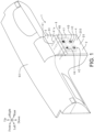
- FIG. 1 shows a layout diagram of the interior member of the present embodiment.
- FIG. 2 shows a transparent rear view (transparent front view) of said interior member.
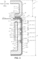
- FIG. 3 shows a cross-sectional view taken along III-III of FIG. 2 .
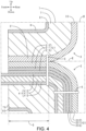
- FIG. 4 shows an enlarged view within a frame IV of FIG. 3 .
- FIG. 5 shows an enlarged view within a frame V of FIG. 3 .
- display regions A1 to D1 for convenience of description of a positional relationship between each member, display regions A1 to D1, a sensor part 4, light sources 90A to 90D and so on are shown as seen through a skin layer 200 and so on.
- an interior member 1 is disposed in a central portion in a left-right direction (vehicle width direction) of an instrument panel (interior part) 92 in a vehicle interior. That is, the interior member 1 is an interior member for vehicles. As shown in FIG. 2 to FIG. 5 , the interior member 1 includes a first skin material 2, a second skin material 3, the sensor part 4, a first stitch 5, a second stitch 6, a flexible part 7, a base 8, and a light source part 9.
- the first skin material 2 includes a first exposed part 20 and a first embedded part 21.
- the first exposed part 20 is exposed to the vehicle interior (cabin interior).
- the first exposed part 20 is in the shape of a flexible sheet having a three-layer structure. That is, from a front side (rear side) toward a back side (front side), the first exposed part 20 includes a skin layer 200, an intermediate layer 201, and a design layer 202.
- the skin layer 200 is made of synthetic leather and is layered.
- the skin layer 200 has a light transmitting property and flexibility.
- a front surface of the skin layer 200 is exposed to the vehicle interior.
- the intermediate layer 201 is disposed on the back side of the skin layer 200.
- the intermediate layer 201 is made of light transmitting ink and is layered.
- the intermediate layer 201 has a light transmitting property and flexibility.
- the intermediate layer 201 has a lower light transmitting property than the skin layer 200. That is, the intermediate layer 201 is semitransparent with a smoky tone.
- the intermediate layer 201 is colored transparent.
- the design layer 202 is disposed on the back side of the intermediate layer 201.
- the design layer 202 is made of light non-transmitting ink and is layered.
- the design layer 202 has a light non-transmitting property and flexibility.
- four recesses 203A to 203D are disposed.
- the design layer 202 (excluding portions where the recesses 203A to 203D are disposed) does not transmit light.
- the four recesses 203A to 203D open on a front surface and a back surface of the design layer 202. That is, the recesses 203A to 203D penetrate the design layer 202 in a front-back direction.
- a space Provided inside the recesses 203A to 203D is a space.
- the recesses 203A to 203D set the display regions A1 to D1 in the first exposed part 20. As shown in FIG.
- a letter “A” is formed in the display region A1 (recess 203A)
- a letter “B” is formed in the display region B1 (recess 203B)
- a letter “C” is formed in the display region C1 (recess 203C)
- a letter “D” is formed in the display region D1 (recess 203D).
- the portions where the display regions A1 to D1 (recesses 203A to 203D) are set have a smaller thickness in the front-back direction than the other portions. Hence, light is likely to be transmitted therethrough.
- the display regions A1 to D1 display the predetermined designs "A" to "D” on the front surface of the skin layer 200 (that is, first exposed part 20).
- the first embedded part 21 is embedded on the front side from an upper edge of the first exposed part 20.
- the first embedded part 21 is not exposed to the vehicle interior.
- the first embedded part 21 is integrally connected to the first exposed part 20. That is, like the first exposed part 20, the first embedded part 21 is in the shape of a flexible sheet having a three-layer structure.
- the first embedded part 21 includes, from a front side (upper side) toward a back side (lower side), a skin layer 210, an intermediate layer 211, and a design layer 212.
- the skin layer 210 and the skin layer 200 are made of the same material and are integrally connected; the intermediate layer 211 and the intermediate layer 201 are made of the same material and are integrally connected; the design layer 202 and the design layer 212 are made of the same material and are integrally connected.
- the second skin material 3 is disposed on the upper side of and side by side with the first skin material 2.
- the second skin material 3 is made of synthetic leather and is in the shape of a sheet.
- the second skin material 3 includes a second exposed part 30 and a second embedded part 31.
- the second exposed part 30 is exposed to the vehicle interior.
- the second exposed part 30 is adjacent to the upper side of the first exposed part 20.
- the second embedded part 31 is embedded on the front side from a lower edge of the second exposed part 30.
- the second embedded part 31 is not exposed to the vehicle interior.
- the second embedded part 31 is integrally connected to the second exposed part 30.
- the second embedded part 31 is disposed on the upper side of the first embedded part 21. As will be described later, the second embedded part 31 is joined to the first embedded part 21.
- the sensor part 4 is disposed on the back side of the first exposed part 20 and on the back side of the first embedded part 21.
- the sensor part 4 includes four sensors (switches for device operation) 4A to 4D. First, a configuration of the four sensors 4A to 4D is described. The four sensors 4A to 4D have similar configurations. The configuration of the sensor 4A is representatively described below.
- the sensor 4A is a capacitive pressure sensor (load sensor).
- the sensor 4A is able to detect a load (pressing force from an operator) input from the front side (vehicle interior inner side).
- the load is included in the concept of "physical quantity" of the present disclosure.
- the sensor 4A includes a main body 40 and a wiring part 41.
- the main body 40 is disposed on the back side of the first exposed part 20. As shown in FIG. 2 , the main body 40 has an annular shape as seen from the front side.
- the main body 40 is in the shape of a flexible sheet having a three-layer structure. That is, as shown in FIG. 3 and FIG. 5 , the main body 40 includes, from the front side toward the back side, a front-side electrode layer 400, an insulation layer 401, and a back-side electrode layer 402.
- the front-side electrode layer 400 is disposed on the back side of the design layer 202.
- the front-side electrode layer 400 is layered and has flexibility.
- the front-side electrode layer 400 includes a styrene-based thermoplastic elastomer and a conductive material containing carbon black.
- the insulation layer 401 is disposed on the back side of the front-side electrode layer 400.
- the insulation layer 401 is layered and has flexibility.
- the insulation layer 401 includes a styrene-based elastomer and an olefin-based elastomer.
- the back-side electrode layer 402 is laminated on the back side of the insulation layer 401.
- the back-side electrode layer 402 is layered and has flexibility.
- the back-side electrode layer 402 is made of the same material as the front-side electrode layer 400.
- input regions A2 to D2 are set in the main body 40.
- the input regions A2 to D2 extend over the entire main body 40.
- the input regions A2 to D2 have an annular shape as seen from the front side.
- the input regions A2 to D2 are disposed around the display regions A1 to D1 as seen from the front side.
- a load is input to the input regions A2 to D2 from the front side. Due to said load, the insulation layer 401 is elastically deformed, and an interelectrode distance (distance in the front-back direction between the front-side electrode layer 400 and the back-side electrode layer 402) changes. That is, the capacitance changes.
- the wiring part 41 is disposed on the back side of the first exposed part 20 and on the back side of the first embedded part 21. As shown in FIG. 2 , the wiring part 41 has a band shape as seen from the front side.
- the wiring part 41 is integrally connected to the main body 40. That is, as shown in FIG. 3 and FIG. 4 , like the main body 40, the wiring part 41 is in the shape of a flexible sheet having a three-layer structure.
- the wiring part 41 includes, from the front side toward the back side, a front-side wiring layer 410, an insulation layer 411, and a back-side wiring layer 412.
- the front-side wiring layer 410 and the front-side electrode layer 400 are made of the same material and are integrally connected; the insulation layer 411 and the insulation layer 401 are made of the same material and are integrally connected; the back-side wiring layer 412 and the back-side electrode layer 402 are made of the same material and are integrally connected.
- one end (rear end) of the wiring part 41 is connected to the main body 40.
- a connector 41a is disposed at the other end (front end) of the wiring part 41.
- the connector 41a corresponds to an "end of a wiring part" of the present disclosure.
- the connector 41a is disposed on the front side of the first embedded part 21, the second embedded part 31, and the flexible part 7.
- a control device (not illustrated) is disposed on the front side of the interior member 1.
- the connector 41a (specifically, front-side wiring layer 410 and back-side wiring layer 412) is electrically connected to the control device via a harness 91.
- the main bodies 40 of the four sensors 4A to 4D are disposed spaced apart at predetermined intervals in the up-down and left-right directions.
- the wiring parts 41 of the four sensors 4A to 4D are spaced apart at predetermined intervals in the left-right direction and extend in the up-down direction on the back side of the first exposed part 20.
- the wiring parts 41 of the four sensors 4A to 4D are spaced apart at predetermined intervals in the left-right direction and extend in the front-rear direction on the back side of the first embedded part 21.
- the first stitch 5 is made of a thread. Like the second stitch 6 shown in FIG. 2 , the first stitch 5 extends in the left-right direction. As shown in FIG. 4 , the first stitch 5 sutures the wiring part 41, the first embedded part 21, and the second embedded part 31 from the lower side toward the upper side. Specifically, the first stitch 5 sutures (joins) the first embedded part 21 and the second embedded part 31. By the first embedded part 21 and the second embedded part 31 joined to each other, an embedded junction O is formed. Also, the first stitch 5 sews the wiring part 41 on a back surface of the first embedded part 21. That is, the wiring part 41 is positioned and fixed with respect to the first embedded part 21.
- the second stitch 6 is made of a thread. As shown in FIG. 2 , the second stitch 6 extends in the left-right direction. As shown in FIG. 4 , the second stitch 6 sutures the wiring part 41 and the first exposed part 20 from the front side (back side) toward the rear side (front side). Specifically, the second stitch 6 sews the wiring part 41 on a back surface of the first exposed part 20. That is, the wiring part 41 is positioned and fixed with respect to the first exposed part 20.
- the second stitch 6 is disposed between a boundary E and the main body 40, the boundary E being between the first exposed part 20 and the second exposed part 30.
- the second stitch 6 protrudes to the rear side (vehicle interior inner side) with respect to the front surface of the first exposed part 20.
- the second stitch 6 is in the shape of dotted lines long in the left-right direction.
- the flexible part 7 includes a first flexible layer 70 and a second flexible layer 71.
- the first flexible layer 70 is disposed on the back side of the first skin material 2 and the sensor part 4.
- the first flexible layer 70 is made of a foam of a thermoplastic elastomer.
- the first flexible layer 70 is layered and has flexibility.
- through holes 700A to 700D are opened in the first flexible layer 70.
- the through holes 700A to 700D serve as both "through holes” and "light introduction holes” of the present disclosure.
- the through holes 700A to 700D penetrate the first flexible layer 70 in the front-back direction.
- first regions A3 to D3 and second regions A4 to D4 are set in the first flexible layer 70.
- the first regions A3 to D3 are disposed on the back side of the input regions A2 to D2.
- the first regions A3 to D3 have an annular shape as seen from the front side.
- the first regions A3 to D3 are disposed around the display regions A1 to D1 as seen from the front side.
- the second regions A4 to D4 are adjacent to the first regions A3 to D3.
- the second regions A4 to D4 are disposed radially inside the first regions A3 to D3 as seen from the front side.
- the second regions A4 to D4 are disposed on the back side of the display regions A1 to D1.
- the second regions A4 to D4 correspond to the through holes (spaces) 700A to 700D.
- the first regions A3 to D3 have higher hardness than the second regions A4 to D4. That is, the first regions A3 to D3 are a high hardness region H.
- the second regions A4 to D4 are a low hardness region L having lower hardness than the high hardness region H.
- the term "hardness" is, for example, hardness measured with an ASKER-C (durometer defined by SRISO101 (standards of the Society of Rubber Science and Technology, Japan)) hardness meter.
- the second flexible layer 71 is disposed on the back side of the second skin material 3.
- the second flexible layer 71 is layered and has flexibility.
- the second flexible layer 71 is made of the same material as the first flexible layer 70.
- the base 8 includes a first base material 80 and a second base material 81.
- the first base material 80 is disposed on the back side of the first flexible layer 70.
- the first base material 80 is made of resin and is layered.
- the first base material 80 has a light transmitting property and flexibility.
- the second base material 81 is disposed on the back side of the second flexible layer 71.
- the second base material 81 is layered and made of the same material as the first base material 80.
- the light source part 9 is disposed on the back side of the base 8. As shown in FIG. 2 and FIG. 3 , the light source part 9 includes the four light sources (LEDs) 90A to 90D. The light sources 90A to 90D are disposed on the back side of the through holes 700A to 700D, respectively. Front surfaces of the light sources 90A to 90D are each able to emit light over the entire surface.
- LEDs light sources
- the display region C1 when the display region C1 is focused, as shown in FIG. 5 , the light from the light source 90C reaches the display region C1 via the base 8 and the through hole 700C. Said light reaches a front surface of the interior member 1 via the display region C1 (recess 203C), the intermediate layer 201, and the skin layer 200. Hence, as shown in FIG. 1 , the design "C" is displayed on the front surface of the interior member 1.
- the interior member of the present embodiment is particularly suitable when the operator operates the interior member 1 while being unable to visually recognize the interior member 1.
- the method is suitable when a vehicle driver operates an interior member (specifically, a device associated with an interior member) while driving.
- the operator touches the front surface of the interior member 1 without visually recognizing the interior member 1.
- the second stitch 6 and the first exposed part 20 are different in material.
- the second stitch 6 (specifically, a rear end of the second stitch 6) protrudes from the front surface of the first exposed part 20.
- the operator is able to recognize the second stitch 6 by the tactile sense.
- the second stitch 6 is disposed on the upper side of and in close proximity to the input regions A2 to D2.
- the operator understands in advance a positional relationship between the second stitch 6 and the input regions A2 to D2.
- the operator is able to, on the basis of a position of the second stitch 6 recognized by the tactile sense, recognize (find out) positions of the desired input regions A2 to D2 by groping.
- the first regions A3 to D3 directly back of the input regions A2 to D2 are the high hardness region H.
- the second regions A4 to D4 adjacent to the first regions A3 to D3 are the low hardness region L.
- the operator is able to, on the basis of a hardness difference between the high hardness region H and the low hardness region L, recognize the positions of the desired input regions A2 to D2 by groping.
- the operator is able to visually recognize the interior member and the light sources 90A to 90D have been turned on, the operator is able to recognize the positions of the desired input regions A2 to D2 on the basis of the designs "A" to "D" displayed on the front surface of the first exposed part 20.
- the main bodies (load detectors) 40 of the sensors 4A to 4D corresponding to the input regions A2 to D2 are compressed.
- the control device drives the device (not illustrated) associated with the main bodies 40 based on a change in the capacitance of the main body 40. In this way, the interior member 1 of the present embodiment is operated.
- a skin material is composed of two divided bodies (first skin material 2 and second skin material 3).
- the wiring part 41 can be routed to a vehicle interior outer side (vehicle interior outer side of the first embedded part 21, the second embedded part 31, the first flexible layer 70, and the second flexible layer 71) of the interior member 1 using the boundary (joint portion or seam) E between the first skin material 2 and the second skin material 3. Accordingly, compared to the case where the skin material is an integral piece, the routing length can be reduced. Thus, the wiring part 41 can be prevented from becoming redundant. The influence (such as deterioration of detection accuracy) of noise (such as electrical resistance or stray capacitance) caused by redundancy of the wiring part 41 on the sensor part 4 can be suppressed.
- the front-side electrode layer 400 is disposed directly back of the design layer 202. That is, the main body 40 is disposed directly back of the first skin material 2 without via another layer (such as a flexible layer). Hence, the pressing force from the operator is likely to be transmitted to the main body 40. Accordingly, operability can be improved.
- the wiring part 41 when the main body 40 is disposed directly back of the first skin material 2, the wiring part 41 is also disposed directly back of the first skin material 2. That is, the wiring part 41, which is not directly related to operation of a device, may cause deterioration of the tactile feel of the operator.
- the wiring part 41 can be prevented from becoming redundant, as described above. Hence, when the operator touches the interior member 1, the operator is less likely to recognize the wiring part 41. Accordingly, even if the wiring part 41 is disposed directly back of the first skin material 2, the tactile feel of the operator is less likely to deteriorate.
- the wiring part 41 can be prevented from becoming redundant, an outline of the wiring part 41 is less likely to appear (less noticeable) on a front surface of the first skin material 2. Hence, the operator is less likely to visually recognize the wiring part 41 through the first skin material 2. Accordingly, even if the wiring part 41 is disposed directly back of the first skin material 2, designability of the interior member 1 can be improved.
- the sensor part 4 is disposed on the back side of the first skin material 2. Hence, while the sensor part 4 can be prevented from being visually recognized from inside of the vehicle interior, the position of the sensor part 4 can be recognized by the tactile sense. Also, the sensor part 4 can be operated.
- the first stitch 5 sutures the first embedded part 21 and the second embedded part 31.
- the first stitch 5 sews the wiring part 41 on the first embedded part 21.
- the wiring part 41 can be fixed to the first embedded part 21.
- An extension direction (left-right direction) of the first stitch 5 and an extension direction (front-rear direction) of the wiring part 41 intersect (are orthogonal to) each other. Hence, a length of a seam allowance can be reduced. Accordingly, an increase in wiring resistance can be suppressed.
- the first stitch 5 is disposed at the embedded junction O (specifically, a rear end of the embedded junction O). The first stitch 5 is not exposed to the vehicle interior. Hence, a good appearance is provided.
- the second stitch 6 is disposed in the first exposed part 20.
- the operator is able to recognize the second stitch 6 by the tactile sense.
- the operator is able to, on the basis of a position of the second stitch 6 recognized by the tactile sense, recognize the positions of the desired input regions A2 to D2.
- the second stitch 6 is in the shape of dotted lines. Hence, the operator is likely to recognize the second stitch 6 by the tactile sense.
- the second stitch 6 sews the wiring part 41 on the first exposed part 20.
- the wiring part 41 can be fixed to the first exposed part 20.
- An extension direction (left-right direction) of the second stitch 6 and an extension direction (up-down direction) of the wiring part 41 intersect (are orthogonal to) each other. Hence, a length of a seam allowance can be reduced. Accordingly, an increase in wiring resistance can be suppressed.
- the connector 41a is disposed on the vehicle interior outer side of the flexible part 7. That is, the wiring part 41 is routed using a boundary between the first flexible layer 70 and the second flexible layer 71. Hence, the wiring part 41 can be prevented from becoming redundant compared to the case where the wiring part 41 is routed to bypass the flexible part 7. The influence of noise caused by redundancy of the wiring part 41 on the sensor part 4 can be suppressed.
- the first regions A3 to D3 directly back of the input regions A2 to D2 are the high hardness region H.
- the second regions A4 to D4 adjacent to the first regions A3 to D3 are the low hardness region L.
- the operator is able to recognize the hardness difference between the high hardness region H and the low hardness region L by the tactile sense from the front side of the first exposed part 20. Hence, the operator is able to recognize the positions of the desired input regions A2 to D2 on the basis of said hardness difference.
- the second regions A4 to D4 include the through holes 700A to 700D.
- the through holes 700A to 700D penetrate the second regions A4 to D4 in the front-back direction. Hence, the hardness of the second regions A4 to D4 can be easily reduced.
- the light sources 90A to 90D are disposed on the back side of the through holes 700A to 700D via the first base material 80. Also, the display regions A1 to D1 are disposed on the front side of the through holes 700A to 700D. Hence, the light from the light sources 90A to 90D can be irradiated to the display regions A1 to D1 from the back side. In this way, the through holes 700A to 700D function as the "light introduction holes" that introduce light into the display regions A1 to D1.
- the first exposed part 20 includes the intermediate layer 201 that is semitransparent.
- the designs "A" to “D” of the display regions A1 to D1 can be prevented from being displayed on the front surface of the first exposed part 20.
- assistance can be provided in displaying the designs "A" to "D” of the display regions A1 to D1 on the front surface of the first exposed part 20.
- the first flexible layer 70 is disposed on the back side of the sensor part 4.
- the first flexible layer 70 is made of an elastomer and has flexibility. Hence, the operator has a good tactile feel when touching the first skin material 2.
- the through holes 700A to 700D are opened in the first flexible layer 70. Hence, the first flexible layer 70 has a high light transmitting property.
- the first base material 80 is disposed on the back side of the first flexible layer 70.
- the first base material 80 has a light transmitting property. Hence, the light from the light sources 90A to 90D can be transmitted to the through holes 700A to 700D of the first flexible layer 70.
- the base 8 is harder than other parts (first skin material 2, second skin material 3, sensor part 4, first stitch 5, second stitch 6, and flexible part 7). Hence, the shape retention of the interior member 1 can be ensured.
- the light sources 90A to 90D and the through holes 700A to 700D are linearly connected in the front-back direction. Hence, a high light transmitting property is provided.
- the light sources 90A to 90D are LEDs. Hence, the light from the light sources 90A to 90D has high straightness (directionality). Accordingly, the light is likely to be introduced into the through holes 700A to 700D.
- a front-side conductive layer (front-side electrode layer 400 and front-side wiring layer 410) and a back-side conductive layer (back-side electrode layer 402 and back-side wiring layer 412) include a styrene-based thermoplastic elastomer as an elastomer component. That is, a conductive layer (front-side conductive layer and back-side conductive layer) includes an elastomer component as a base material. Hence, the conductive layer is flexible.
- An interior member of the present embodiment differs from the interior member of the first embodiment in that no first stitch is disposed, and that the second stitch does not fix the wiring part to the first exposed part. Here, only the differences will be described.
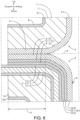
- FIG. 6 shows a partial cross-sectional view in the up-down direction of the interior member of the present embodiment. Portions corresponding to those in FIG. 4 are denoted by the same reference numerals.
- there is no first stitch 5 (see FIG. 4 ) disposed at the embedded junction O.
- a front surface of the first embedded part 21 (skin layer 210) and a front surface of the second embedded part 31 are bonded.
- a front surface of the wiring part 41 front-side wiring layer 410) is bonded to the back surface of the first embedded part 21 (design layer 212).
- the second stitch 6 is a stitch-like molded product. That is, the second stitch 6 is a pseudo stitch.
- the second stitch 6 is fixed to the front surface of the first exposed part 20 (skin layer 200).
- the second stitch 6 protrudes from the front surface of the first exposed part 20.
- the front surface of the wiring part 41 front-side wiring layer 410) is bonded to the back surface of the first exposed part 20 (design layer 202).
- the interior member of the present embodiment and the interior member of the first embodiment have similar effects with respect to portions having common configurations.
- the first stitch may not be disposed. That is, at the embedded junction O, the first embedded part 21 and the second embedded part 31 may be bonded together.
- the wiring part 41 may be bonded to the first embedded part 21. In this way, a seam allowance caused by the first stitch can be removed from the wiring part 41. Hence, an increase in wiring resistance can be suppressed.
- the second stitch 6 may be a pseudo stitch.
- the wiring part 41 may be bonded to the first exposed part 20. In this way, a seam allowance caused by the second stitch 6 can be removed from the wiring part 41. Hence, an increase in wiring resistance can be suppressed. Even in this case, the operator is able to recognize the second stitch 6 by the tactile sense.
- An interior member of the present embodiment differs from the interior member of the first embodiment in that a first region corresponds to a low hardness region and a second region corresponds to a high hardness region. Here, only the differences will be described.
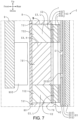
- FIG. 7 shows a partial cross-sectional view in the up-down direction of the interior member of the present embodiment. Portions corresponding to those in FIG. 5 are denoted by the same reference numerals.
- the first flexible layer 70 includes a hard part 701 and a soft part 702.
- the hard part 701 and the soft part 702 are both made of an elastomer.
- the hard part 701 has higher hardness than the soft part 702. That is, a hardness difference is set between the hard part 701 and the soft part 702.
- the soft part 702 has an annular shape as seen from the front side.
- the soft part 702 is disposed in the first region C3.
- the first region C3 is the low hardness region L.
- the hard part 701 is disposed in a portion other than the soft part 702 in the first flexible layer 70.
- the second region C4 is the high hardness region H.
- the hard part 701 has a light transmitting property. Hence, the light from the light source 90C is able to be transmitted through the hard part 701.
- the interior member of the present embodiment and the interior member of the first embodiment have similar effects with respect to portions having common configurations.
- the first region C3 may be the low hardness region L as in the interior member 1 of the present embodiment.
- the second region C4 may be the high hardness region H. Even in this case, the operator is able to recognize the input region C2 by the tactile sense.
- the first region C3 (low hardness region L) is compressed and deformed (sinks) to the back side.
- the second region C4 high hardness region H guides the compression and deformation of the first region C3 from radially inside. Hence, a deformation direction of the first region C3 is likely to be stabilized.
- FIG. 8(A) shows a partial cross-sectional view in the up-down direction of an interior member of another embodiment (part 1).
- FIG. 8(B) shows a partial cross-sectional view in the up-down direction of an interior member of another embodiment (part 2).
- FIG. 8(C) shows a partial cross-sectional view in the up-down direction of an interior member of another embodiment (part 3).
- Portions corresponding to those in FIG. 7 are denoted by the same reference numerals. Portions shown in FIG. 8(A) to FIG. 8(C) correspond to those within a frame VIII of FIG. 7 .
- the first flexible layer 70 of another embodiment includes the hard part 701 and the soft part 702.
- the soft part 702 is made of a foam of an elastomer.
- the hard part 701 is integrally connected to the soft part 702.
- the foam forming the soft part 702 is impregnated with resin. That is, the hard part 701 is made of a foam impregnated with resin.
- the high hardness region H (second region C4) and the low hardness region L (first region C3) can be easily set.
- the amount of resin for impregnating the hard part 701 is not particularly limited.
- the soft part 702 (low hardness region L) may be impregnated with resin. It is sufficient if a difference in resin impregnation rate can be set between the hard part 701 and the soft part 702.
- the first flexible layer 70 of another embodiment includes a thin part 703 and a thick part 704.
- the thin part 703 has a smaller thickness in the front-back direction than the thick part 704.
- the thin part 703 has lower hardness than the thick part 704.
- the thin part 703 corresponds to the low hardness region L
- the thick part 704 corresponds to the high hardness region H.
- the present embodiment by partially reducing the thickness in the front-back direction (front-rear direction) of the first flexible layer 70, the high hardness region H (first region C3) and the low hardness region L (second region C4) can be easily set.
- the thickness in the front-back direction of the thick part 704 (high hardness region H) may be made smaller than the original thickness in the front-back direction of the first flexible layer 70. It is sufficient if a difference in thickness in the front-back direction can be set between the thin part 703 and the thick part 704.
- a plurality of through holes 700C are opened in the first flexible layer 70 of another embodiment (part 3).
- the through holes 700C penetrate the first flexible layer 70 in the front-back direction (front-rear direction).
- the high hardness region H first region C3
- the low hardness region L second region C4
- the through hole 700C may be disposed in the high hardness region H.
- the diameter, number disposed and shape of the through holes 700C are not particularly limited. It is sufficient if a difference in aperture ratio of the through hole 700C can be set between the high hardness region H and the low hardness region L.
- the stitch type of the first stitch 5 shown in FIG. 4 is not particularly limited. Examples thereof may include straight stitch, chain stitch, fly stitch, blanket stitch, French knot stitch, cross stitch, back stitch, outline stitch, feather stitch, herringbone stitch, couching stitch, and chevron stitch.
- the number of the first stitch 5 disposed is not particularly limited. The number disposed may be single (single stitch) or plural (for example, double stitch). The same applies to the second stitch 6.
- the first stitch 5 shown in FIG. 4 may be combined into the form shown in FIG. 6 . That is, the first embedded part 21 and the second embedded part 31 may be bonded together, the wiring part 41 may be bonded to the first embedded part 21, and the wiring part 41, the first embedded part 21, and the second embedded part 31 may be sutured by the first stitch 5. In this way, a joining strength between the wiring part 41 and the first embedded part 21 and between the first embedded part 21 and the second embedded part 31 is increased.
- the first stitch 5 functions both as a “skin material joining member” that joins the first skin material 2 and the second skin material 3, and as a “first wiring part fixing member” that fixes the wiring part 41 to the first skin material 2.
- the second stitch 6 functions as a "second wiring part fixing member” that fixes the wiring part 41 to the first skin material 2.
- a stapler, a rivet or the like may be used as the "skin material joining member," the "first wiring part fixing member,” and the "second wiring part fixing member.”
- the second stitch 6 functions as an "input position notification member" that indirectly informs the operator of the positions of the input regions A2 to D2.
- the second stitch 6 (pseudo stitch) shown in FIG. 6 does not function as the "second wiring part fixing member," but only functions as the "input position notification member.”
- a predetermined design may be threedimensionally disposed on the front surface of the first exposed part 20 as the "input position notification member.” Even in this case, the operator is able to recognize the design by the tactile sense.
- the predetermined design may be planarly disposed as the "input position notification member.” Even in this case, by setting a difference in coefficient of friction between a front surface of the design and the front surface of the first exposed part 20, the operator is able to recognize the design by the tactile sense.
- examples of the design disposed as the "input position notification member” include at least one selected from a pattern (such as polka dot pattern, stripe pattern, lattice pattern, wood grain pattern, or marble pattern), a letter (such as alphabet, hiragana character, katakana character, kanji character, number, or braille character), a shape (such as dot, straight line, dotted lines, dashdotted lines, polygon or circle), and a symbol (such as button for device operation, or icon indicating device status).
- a pattern such as polka dot pattern, stripe pattern, lattice pattern, wood grain pattern, or marble pattern
- a letter such as alphabet, hiragana character, katakana character, kanji character, number, or braille character
- a shape such as dot, straight line, dotted lines, dashdotted lines, polygon or circle
- a symbol such as button for device operation, or icon indicating device status
- the second stitch 6 may not be disposed in the interior member 1.
- the boundary E is sunk on the front side from the front surfaces (portions of the front surfaces that protrude most rearward) of the first exposed part 20 and the second exposed part 30.
- the operator is able to recognize the boundary E by the tactile sense. Accordingly, the operator is able to, on the basis of a position of the boundary E, recognize (find out) the positions of the desired input regions A2 to D2 by groping.
- a bonding manner between the first embedded part 21 and the second embedded part 31 shown in FIG. 6 is not particularly limited.
- the first embedded part 21 and the second embedded part 31 may be directly bonded (including fusion bonded).
- the first embedded part 21 and the second embedded part 31 may be indirectly bonded via a bonding layer (which may be a single layer or multiple layers). The same applies to the bonding form between the wiring part 41 and the first embedded part 21 and the bonding form between the wiring part 41 and the first exposed part 20.
- the first exposed part 20 and the first embedded part 21 may have the same or different configurations.
- the first exposed part 20 may include the skin layer 200, the intermediate layer 201 and the design layer 202, while the first embedded part 21 may include only the skin layer 210. That is, the first embedded part 21 may not include the intermediate layer 211 and the design layer 212.
- the configuration of the flexible part 7 is not particularly limited.
- the first flexible layer 70 and the second flexible layer 71 may be integrated into one piece.
- the configuration of the base 8 is not particularly limited.
- the first base material 80 and the second base material 81 may be integrated into one piece.
- the configuration of the sensor part 4 is not particularly limited.
- the number of sensors 4A to 4D disposed may be single or plural.
- an intersection portion where the front-side electrode layer 400, the insulation layer 401 and the back-side electrode layer 402 are laminated (see FIG. 5 )) of a plurality of front-side electrode layers 400 of a band shape and a plurality of back-side electrode layers 402 of a band shape that are disposed in a grid pattern as seen from the front side may be set as the input regions A2 to D2.
- the type of the sensors 4A to 4D is not particularly limited. Examples thereof may include capacitive sensor, resistive film sensor, strain gauge sensor, and piezoelectric effect sensor. It is sufficient if a physical quantity input by the operator touching the first exposed part 20 can be detected.
- the type of the physical quantity is not particularly limited. Examples thereof include length, mass, time, current, load, pressure, and energy.
- a tactile switch or an actuator may be disposed instead of the sensors 4A to 4D.
- the actuator for example, an electrostatic actuator, an electromagnetic actuator, or a piezoelectric actuator may be disposed.
- the electrostatic actuator may include the front-side electrode layer 400, the insulation layer 401, and the back-side electrode layer 402 (see FIG. 5 ).
- the wiring part 41 shown in FIG. 6 may not include the insulation layer 411. It is sufficient if insulation between the front-side wiring layer 410 and the back-side wiring layer 412 can be ensured.
- the type of the front-side wiring layer 410 and the back-side wiring layer 412 is not particularly limited. Examples thereof may include a conductive sheet and a conductive wire.
- the configuration of the end of the wiring part 41 is not particularly limited. Examples thereof may include a connector, a coupler, and a terminal. The end may be the wiring part 41 itself (for example, an end of a conductive sheet or an end of a conductive wire).
- the sensor 4A includes the input region A2, the sensor 4B includes the input region B2, the sensor 4C includes the input region C2, and the sensor 4D includes the input region D2.
- the first region A3 is disposed on the back side of the input region A2, the first region B3 is disposed on the back side of the input region B2, the first region C3 is disposed on the back side of the input region C2, and the first region D3 is disposed on the back side of the input region D2.
- a hardness difference may be set between at least two of the first regions A3 to D3.
- any first region corresponds to the high hardness region H
- another first region corresponds to the low hardness region L.
- the method for setting the hardness difference applies to FIG. 5 and FIG. 8(A) to FIG. 8(C) .
- the number disposed, position, size, shape and so on of the recesses 203A to 203D shown in FIG. 2 , FIG. 3 , and FIG. 5 are not particularly limited.
- the number of display regions A1 to D1 disposed and the number of recesses 203A to 203D disposed may be the same or different.
- a single display region A1 to D1 may be formed by a plurality of recesses 203A to 203D.
- a plurality of display regions A1 to D1 may be formed by a single recess 203A to 203D.
- the positions of openings of the recesses 203A to 203D are not particularly limited.
- the recesses 203A to 203D may open on the front surface or the back surface of the design layer 202.
- positions of bottoms of the recesses 203A to 203D may be within the design layer 202, on the front surface of the front-side electrode layer 400, within the front-side electrode layer 400, or the like.
- the positions of the bottoms of the recesses 203A to 203D may be within the design layer 202, on the back surface of the intermediate layer 201, within the intermediate layer 201, or the like.
- the display regions A1 to D1 are disposed in at least the design layer 202 according to the number disposed, position, size, shape and so on of the recesses 203A to 203D. That is, it is sufficient if the design layer 202 includes at least a portion of the display regions A1 to D1.
- the on/off mode of the light sources 90A to 90D is not particularly limited.
- the interior member 1 may include a trigger sensor for turning on the light sources 90A to 90D.
- the light sources 90A to 90D may be always on.
- the light sources 90A to 90D may be turned on and off in conjunction with vehicle lights (such as an interior light or a headlight).
- a design displayed on the first exposed part 20 by the display regions A1 to D1 is not particularly limited. Examples thereof include a design (at least one selected from a pattern, a letter, a shape, and a symbol) disposed as the "input position notification member" described above.
- the design displayed on the first exposed part 20 may be in a single color or in multiple colors. It is sufficient if the color or colors are exhibited on the first exposed part 20 by at least one selected from the skin layer 200, the intermediate layer 201, the design layer 202, and the light sources 90A to 90D.
- the light transmitting property of the skin layer 200 and the intermediate layer 201 is not particularly limited.
- the skin layer 200 and the intermediate layer 201 may be colorless transparent, colored transparent, or semitransparent.
- the design layer 202 may not have a light non-transmitting property. That is, it is sufficient if the design layer 202 has a lower light transmitting property than the intermediate layer 201.
- the color (hue, saturation, or brightness) of the skin layer 200, the intermediate layer 201, the design layer 202, and the light sources 90A to 90D is not particularly limited.
- the luminance of the light sources 90A to 90D is not particularly limited.
- the type, number disposed, and position of the light sources 90A to 90D are not particularly limited.
- the light sources 90A to 90D may be organic EL sheets, inorganic EL sheets, phosphorescent sheets, or the like.
- the light source part 9 may include the light sources 90A to 90D and a light guide plate (for example, an acrylic plate).
- the light sources 90A to 90D may be disposed adjacent to the first base material 80 in a plane direction to cause a front surface of the first base material 80 to emit light from the surface.
- the interior part in which the interior member 1 is disposed is not particularly limited. Examples thereof include a door trim, a seat, a floor, a ceiling, an instrument panel, a glove box, a steering wheel, a center console, and a register.
- An installation surface of the interior member 1 in the interior part may be a flat surface or a curved surface.
- a direction (front-back direction) in which the interior member 1 is installed is not particularly limited.
- the interior member 1 may be disposed in an interior part of, other than vehicles, a ship, an aircraft, a building, or a house.
- a layer configuration of the interior member 1 is not particularly limited.
- the sensor part 4, the flexible part 7, and the base 8 another layer may be interposed between two layers adjacent in the front-back direction.
- Another layer may be disposed on the front side of the first skin material 2.
- the skin material is composed of two divided bodies (first skin material 2 and second skin material 3), but the number of divided bodies is not particularly limited.
- the material of the skin layers 200, 210 and the second skin material 3 is not particularly limited. Examples thereof include synthetic leather, resin, elastomers, nonwoven fabrics, and various fabrics (such as woven fabrics and knitted fabrics). Specific examples of synthetic leather, resin, and elastomers include acrylic, polyethylene terephthalate, polycarbonate, polyvinyl chloride, silicone, epoxy, polyurethane, styrene-based thermoplastic elastomers, olefin-based thermoplastic elastomers, and dynamic crosslinking thermoplastic elastomers. Examples of nonwoven fabrics and various fabrics include polyester, polypropylene, nylon, and cotton.
- the skin layers 200, 210 and the second skin material 3 may contain a coloring agent (such as colored polyethylene), a light diffusing agent (such as silicone, acrylic, and titanium oxide), and a light absorbing agent (such as titanium black and carbon black).
- the material of the intermediate layers 201 and 211 is not particularly limited. Examples thereof include resin and elastomers, such as acrylic, polyethylene terephthalate, polycarbonate, polyvinyl chloride, silicone, polyester, epoxy, polyurethane, styrene-based thermoplastic elastomers, olefin-based thermoplastic elastomers, and dynamic crosslinking thermoplastic elastomers.
- the intermediate layers 201 and 211 may contain the coloring agent, light diffusing agent, and light absorbing agent described above.
- the material of the design layers 202 and 212 is not particularly limited. Examples thereof include resin and elastomers, such as acrylic, polyethylene terephthalate, polycarbonate, polyvinyl chloride, silicone, polyester, epoxy, polyurethane, styrene-based thermoplastic elastomers, olefin-based thermoplastic elastomers, and dynamic crosslinking thermoplastic elastomers.
- the design layers 202 and 212 may contain the coloring agent, light diffusing agent, and light absorbing agent described above.
- the material of the first flexible layer 70 and the second flexible layer 71 is not particularly limited. Examples thereof include elastomers such as styrene-based thermoplastic elastomers, olefin-based thermoplastic elastomers, and dynamic crosslinking thermoplastic elastomers, and foam such as polyurethane foam. In the case where the first flexible layer 70 includes the through holes 700A to 700D, the light transmitting property due to the material is not required.
- the material of the insulation layer is not particularly limited.
- the thermoplastic elastomer for the insulation layer is not particularly limited, and may be appropriately selected from styrene-based, olefin-based, vinyl chloride-based, urethane-based, ester-based, and amide-based elastomers. One type or two or more types of thermoplastic elastomers may be used.
- styrene-based thermoplastic elastomer examples include styrene-butadiene-styrene block copolymer (SBS), styrene-ethylene-butylene-styrene block copolymer (SEBS), and styrene-ethylene-propylene-styrene block copolymer (SEPS).
- SBS styrene-butadiene-styrene block copolymer
- SEBS styrene-ethylene-butylene-styrene block copolymer
- SEPS styrene-ethylene-propylene-styrene block copolymer
- olefin-based elastomer examples include, in addition to ethylene ethyl acrylate (EEA), ethylene methyl acrylate (EMA), and ethylene methyl methacrylate copolymer (EMMA), copolymer (ethylene-octene copolymer
- Rubber, resin, or foam other than thermoplastic elastomers may be used for the insulation layer.
- examples thereof include: rubber such as ethylene propylene rubber (ethylene propylene copolymer (EPM) or ethylene propylene diene terpolymer (EPDM)), or resin such as acrylic, polyethylene terephthalate, polycarbonate, polyvinyl chloride, silicone, polyester, and epoxy, and foam such as polyurethane foam.
- EPM ethylene propylene copolymer
- EPDM ethylene propylene diene terpolymer
- resin such as acrylic, polyethylene terephthalate, polycarbonate, polyvinyl chloride, silicone, polyester, and epoxy
- foam such as polyurethane foam.
- the material of the conductive layer (front-side conductive layer (front-side electrode layer 400 and front-side wiring layer 410) and back-side conductive layer (back-side electrode layer 402 and back-side wiring layer 412)) is not particularly limited.
- the conductive layer preferably has conductivity and is flexible. Examples of the material of the conductive layer include conductive rubber and conductive cloth.
- the conductive rubber includes an elastomer and a conductive material.
- the elastomer at least one selected from crosslinked rubbers such as acrylic rubber, silicone rubber, urethane rubber, urea rubber, fluororubber, nitrile rubber, and hydrogenated nitrile rubber, and thermoplastic elastomers may be used.
- the conductive material may be appropriately selected from among: metal particles made of silver, gold, copper, nickel, rhodium, palladium, chromium, titanium, platinum, iron, and alloys thereof; metal oxide particles made of zinc oxide, titanium oxide or the like; metal carbide particles made of titanium carbonate or the like; metal nanowires made of silver, gold, copper, platinum, nickel, or the like; and conductive carbon materials such as carbon black, carbon nanotube, graphite, thin layer graphite, and graphene.
- the conductive rubber may contain a crosslinking agent, a crosslinking accelerator, a dispersant, a reinforcing material, a plasticizer, an anti-aging agent, a coloring agent, or the like.
- conductive cloth a woven fabric, a nonwoven fabric, or the like of conductive fibers may be used.
- the conductive fibers include those obtained by plating highly conductive copper, nickel, or the like on polyester fibers such as polyethylene terephthalate (PET).
- the material of the first base material 80 and the second base material 81 is not particularly limited. Examples thereof include resin and elastomers, such as acrylic, polyethylene terephthalate, polycarbonate, polyvinyl chloride, silicone, polyester, epoxy, polyurethane, styrene-based thermoplastic elastomers, olefin-based thermoplastic elastomers, and dynamic crosslinking thermoplastic elastomers. In order to ensure the shape retention of the interior member 1, it is sufficient if the first base material 80 and the second base material 81 are harder than the other layers (first skin material 2, second skin material 3, sensor part 4, first flexible layer 70, and second flexible layer 71).
- resin and elastomers such as acrylic, polyethylene terephthalate, polycarbonate, polyvinyl chloride, silicone, polyester, epoxy, polyurethane, styrene-based thermoplastic elastomers, olefin-based thermoplastic elastomers, and dynamic crosslinking thermoplastic elastomers
- a member (for example, base 8, flexible part 7, and sensor part 4) interposed between the light sources 90A to 90D and the display regions A1 to D1 may have a light transmitting property or a light diffusing property.
- a method for imparting the light diffusing property to these members is not particularly limited.
- a light diffusing agent such as silicone, acrylic, or titanium oxide
- These members may have a light introduction hole.
- a method for laminating the skin layer 200, the intermediate layer 201, and the design layer 202 in the first skin material 2 shown in FIG. 4 is not particularly limited. Screen printing, gravure printing, inkjet printing, flexo printing or the like may be used. The layers may be laminated by bonding, vapor deposition or the like. The same applies to a method for laminating the skin layer 210, the intermediate layer 211, and the design layer 212.
- a method for forming the recesses 203A to 203D with respect to the first skin material 2 is not particularly limited. Laser processing, photoetching or the like may be used.
- a method for fixing the sensors 4A to 4D, the first skin material 2 and the first flexible layer 70 shown in FIG. 3 is not particularly limited.
- the installation surface of the interior member 1 in the interior part is a convex surface that bulges out to the front side
- another layer inside a radius of curvature of the curve come into pressure contact with the base 8 inside the radius of curvature.
- the sensors 4A to 4D, the first skin material 2 and the first flexible layer 70 can be fixed using the pressure contact force.
- the pressure contact force described above does not act.
- the sensors 4A to 4D, the first skin material 2 and the first flexible layer 70 can be fixed using adhesive, double-sided tape or the like.
- 1 interior member; 2: first skin material; 20: first exposed part; 200: skin layer; 201: intermediate layer; 202: design layer; 203A to 203D: recess; 21: first embedded part; 210: skin layer; 211: intermediate layer; 212: design layer; 3: second skin material; 30: second exposed part; 31: second embedded part; 4: sensor part; 4A to 4D: sensor; 40: main body; 400: front-side electrode layer; 401: insulation layer; 402: back-side electrode layer; 41: wiring part; 41a: connector (end of wiring part); 410: front-side wiring layer; 411: insulation layer; 412: back-side wiring layer; 5: first stitch; 6: second stitch; 7: flexible part; 70: first flexible layer; 700A to 700D: through hole (light introduction hole); 701: hard part; 702: soft part; 703: thin part; 704: thick part; 71: second flexible layer; 8: base; 80: first base material; 81: second base material; 9: light source part
Landscapes
- Engineering & Computer Science (AREA)
- Mechanical Engineering (AREA)
- General Engineering & Computer Science (AREA)
- Theoretical Computer Science (AREA)
- Human Computer Interaction (AREA)
- Physics & Mathematics (AREA)
- General Physics & Mathematics (AREA)
- Vehicle Interior And Exterior Ornaments, Soundproofing, And Insulation (AREA)
Abstract
Description
- The present disclosure relates to an interior member with a skin material, which is used in, for example, the interior of a vehicle.
- In the field of vehicle interiors, the development of interior members in which switches for device operation are embedded is progressing. As an example, a lid of a console box of
Patent Document 1 includes, from the front side toward the back side, a skin material, a switch, and a base material. The skin material includes, from the front side toward the back side, a surface layer and a cushion layer. - On a front surface of the surface layer, a design (a large number of light spots arranged in a grid pattern) corresponding to the switch is displayed by backlighting. An operator is able to grasp a position of the switch by visually recognizing said design. By pressing said design, the operator is able to press the switch via the surface layer and the cushion layer.
- The skin material bypasses the base material, that is, an outer edge of the lid, and is rolled from a front surface into a back surface of the base material. An end of the skin material is joined to the back surface of the base material. Along with the skin material, a wire connected to the switch bypasses the outer edge of the lid and is rolled from the front surface into the back surface of the base material. A cover member is adjacent to a lower side of the lid. The cover member covers an opening of a box body of the console box. The cover member is not exposed to a vehicle interior.
- Patent Document 1:
Japanese Patent Laid-open No. 2019-188919 - However, when the wire is routed to bypass the outer edge of the lid, a routing length (wire length) may be increased. That is, the wire may become redundant. The cushion layer is flexible. Hence, when the switch is disposed on the back side of the cushion layer, a pressing force from the operator is likely to be absorbed by the cushion layer. Accordingly, the pressing force is less likely to be transmitted to the switch. In this way, when the switch is disposed on the back side of the cushion layer, operability deteriorates. In this regard, operability can be improved when the switch is disposed on the front side of the cushion layer. However, in this way, the wire may also be disposed on the front side of the cushion layer. Hence, the operator is likely to recognize the wire through the surface layer by the tactile sense or the visual sense. Accordingly, the wire that is not directly related to operation of a device may cause deterioration of the tactile feel of the operator. The appearance of the lid may deteriorate and designability may be impaired. Accordingly, an object of the present disclosure is to provide an interior member in which a wiring part can be prevented from becoming redundant, the tactile feel can be prevented from deteriorating, and designability can be improved.
- In order to solve the above problems, an interior member of the present disclosure includes a first skin material, a second skin material, and a transducer. The first skin material includes: a first exposed part, exposed to a cabin interior; and a first embedded part, embedded on a cabin exterior side from the first exposed part. The second skin material includes: a second exposed part, exposed to the cabin interior and adjacent to the first exposed part; and a second embedded part, embedded on the cabin exterior side from the second exposed part and joined to the first embedded part. The transducer includes: a main body, disposed directly back of the first exposed part; and a wiring part, disposed directly back of at least the first embedded part and electrically connected to the main body. An end of the wiring part is disposed on the cabin exterior side of the first embedded part.
- According to the interior member of the present disclosure, the wiring part is routed using a joint portion between the first skin material and the second skin material. Hence, the wiring part can be prevented from becoming redundant compared to the case where the wiring part is routed to bypass an outer edge of the interior member. Since the wiring part can be prevented from becoming redundant, the operator is less likely to touch the wiring part and visually recognize the wiring part through the first skin material. Accordingly, the tactile feel can be prevented from deteriorating and designability can be improved.
-
- [
FIG. 1] FIG. 1 is a layout diagram of an interior member of a first embodiment. - [
FIG. 2] FIG. 2 is a transparent rear view of said interior member. - [
FIG. 3] FIG. 3 is a cross-sectional view taken along III-III ofFIG. 2 . - [
FIG. 4] FIG. 4 is an enlarged view within a frame IV ofFIG. 3 . - [
FIG. 5] FIG. 5 is an enlarged view within a frame V ofFIG. 3 . - [
FIG. 6] FIG. 6 is a partial cross-sectional view in an up-down direction of an interior member of a second embodiment. - [
FIG. 7] FIG. 7 is a partial cross-sectional view in the up-down direction of an interior member of a third embodiment. - [
FIG. 8] FIG. 8(A) is a partial cross-sectional view in the up-down direction of an interior member of another embodiment (part 1).FIG. 8(B) is a partial cross-sectional view in the up-down direction of an interior member of another embodiment (part 2).FIG. 8(C) is a partial cross-sectional view in the up-down direction of an interior member of another embodiment (part 3). - Hereinafter, embodiments of an interior member of the present disclosure will be described.
- First, an arrangement and a configuration of an interior member of the present embodiment are described. In the drawings hereinafter, a rear side corresponds to a "cabin interior side" of the present disclosure, and a front side corresponds to a "cabin exterior side" of the present disclosure.
FIG. 1 shows a layout diagram of the interior member of the present embodiment.FIG. 2 shows a transparent rear view (transparent front view) of said interior member.FIG. 3 shows a cross-sectional view taken along III-III ofFIG. 2 .FIG. 4 shows an enlarged view within a frame IV ofFIG. 3 .FIG. 5 shows an enlarged view within a frame V ofFIG. 3 . InFIG. 2 , for convenience of description of a positional relationship between each member, display regions A1 to D1, asensor part 4,light sources 90A to 90D and so on are shown as seen through askin layer 200 and so on. - As shown in
FIG. 1 , aninterior member 1 is disposed in a central portion in a left-right direction (vehicle width direction) of an instrument panel (interior part) 92 in a vehicle interior. That is, theinterior member 1 is an interior member for vehicles. As shown inFIG. 2 to FIG. 5 , theinterior member 1 includes afirst skin material 2, asecond skin material 3, thesensor part 4, afirst stitch 5, asecond stitch 6, aflexible part 7, abase 8, and alight source part 9. - The
first skin material 2 includes a firstexposed part 20 and a first embeddedpart 21. The firstexposed part 20 is exposed to the vehicle interior (cabin interior). The firstexposed part 20 is in the shape of a flexible sheet having a three-layer structure. That is, from a front side (rear side) toward a back side (front side), the firstexposed part 20 includes askin layer 200, anintermediate layer 201, and adesign layer 202. - The
skin layer 200 is made of synthetic leather and is layered. Theskin layer 200 has a light transmitting property and flexibility. A front surface of theskin layer 200 is exposed to the vehicle interior. Theintermediate layer 201 is disposed on the back side of theskin layer 200. Theintermediate layer 201 is made of light transmitting ink and is layered. Theintermediate layer 201 has a light transmitting property and flexibility. Theintermediate layer 201 has a lower light transmitting property than theskin layer 200. That is, theintermediate layer 201 is semitransparent with a smoky tone. Theintermediate layer 201 is colored transparent. - The
design layer 202 is disposed on the back side of theintermediate layer 201. Thedesign layer 202 is made of light non-transmitting ink and is layered. Thedesign layer 202 has a light non-transmitting property and flexibility. In thedesign layer 202, four recesses 203A to 203D are disposed. The design layer 202 (excluding portions where the recesses 203A to 203D are disposed) does not transmit light. - The four recesses 203A to 203D open on a front surface and a back surface of the
design layer 202. That is, the recesses 203A to 203D penetrate thedesign layer 202 in a front-back direction. Provided inside the recesses 203A to 203D is a space. The recesses 203A to 203D set the display regions A1 to D1 in the firstexposed part 20. As shown inFIG. 2 , as seen from the front side, a letter "A" is formed in the display region A1 (recess 203A), a letter "B" is formed in the display region B1 (recess 203B), a letter "C" is formed in the display region C1 (recess 203C), and a letter "D" is formed in the display region D1 (recess 203D). As shown inFIG. 3 andFIG. 5 , in the firstexposed part 20, the portions where the display regions A1 to D1 (recesses 203A to 203D) are set have a smaller thickness in the front-back direction than the other portions. Hence, light is likely to be transmitted therethrough. As shown in black inFIG. 1 , by light irradiated from the back side, the display regions A1 to D1 display the predetermined designs "A" to "D" on the front surface of the skin layer 200 (that is, first exposed part 20). - The first embedded
part 21 is embedded on the front side from an upper edge of the firstexposed part 20. The first embeddedpart 21 is not exposed to the vehicle interior. The first embeddedpart 21 is integrally connected to the firstexposed part 20. That is, like the firstexposed part 20, the first embeddedpart 21 is in the shape of a flexible sheet having a three-layer structure. The first embeddedpart 21 includes, from a front side (upper side) toward a back side (lower side), askin layer 210, anintermediate layer 211, and adesign layer 212. Theskin layer 210 and theskin layer 200 are made of the same material and are integrally connected; theintermediate layer 211 and theintermediate layer 201 are made of the same material and are integrally connected; thedesign layer 202 and thedesign layer 212 are made of the same material and are integrally connected. - The
second skin material 3 is disposed on the upper side of and side by side with thefirst skin material 2. Thesecond skin material 3 is made of synthetic leather and is in the shape of a sheet. Thesecond skin material 3 includes a secondexposed part 30 and a second embeddedpart 31. The secondexposed part 30 is exposed to the vehicle interior. The secondexposed part 30 is adjacent to the upper side of the firstexposed part 20. - The second embedded
part 31 is embedded on the front side from a lower edge of the secondexposed part 30. The second embeddedpart 31 is not exposed to the vehicle interior. The second embeddedpart 31 is integrally connected to the secondexposed part 30. The second embeddedpart 31 is disposed on the upper side of the first embeddedpart 21. As will be described later, the second embeddedpart 31 is joined to the first embeddedpart 21. - The
sensor part 4 is disposed on the back side of the firstexposed part 20 and on the back side of the first embeddedpart 21. Thesensor part 4 includes four sensors (switches for device operation) 4A to 4D. First, a configuration of the four sensors 4A to 4D is described. The four sensors 4A to 4D have similar configurations. The configuration of the sensor 4A is representatively described below. - The sensor 4A is a capacitive pressure sensor (load sensor). The sensor 4A is able to detect a load (pressing force from an operator) input from the front side (vehicle interior inner side). The load is included in the concept of "physical quantity" of the present disclosure. The sensor 4A includes a
main body 40 and awiring part 41. - The
main body 40 is disposed on the back side of the firstexposed part 20. As shown inFIG. 2 , themain body 40 has an annular shape as seen from the front side. Themain body 40 is in the shape of a flexible sheet having a three-layer structure. That is, as shown inFIG. 3 andFIG. 5 , themain body 40 includes, from the front side toward the back side, a front-side electrode layer 400, aninsulation layer 401, and a back-side electrode layer 402. The front-side electrode layer 400 is disposed on the back side of thedesign layer 202. The front-side electrode layer 400 is layered and has flexibility. The front-side electrode layer 400 includes a styrene-based thermoplastic elastomer and a conductive material containing carbon black. - The
insulation layer 401 is disposed on the back side of the front-side electrode layer 400. Theinsulation layer 401 is layered and has flexibility. Theinsulation layer 401 includes a styrene-based elastomer and an olefin-based elastomer. The back-side electrode layer 402 is laminated on the back side of theinsulation layer 401. The back-side electrode layer 402 is layered and has flexibility. The back-side electrode layer 402 is made of the same material as the front-side electrode layer 400. - As shown in
FIG. 2 ,FIG. 3 , andFIG. 5 , input regions A2 to D2 are set in themain body 40. The input regions A2 to D2 extend over the entiremain body 40. The input regions A2 to D2 have an annular shape as seen from the front side. The input regions A2 to D2 are disposed around the display regions A1 to D1 as seen from the front side. A load is input to the input regions A2 to D2 from the front side. Due to said load, theinsulation layer 401 is elastically deformed, and an interelectrode distance (distance in the front-back direction between the front-side electrode layer 400 and the back-side electrode layer 402) changes. That is, the capacitance changes. - As shown by dotted lines in
FIG. 1 , thewiring part 41 is disposed on the back side of the firstexposed part 20 and on the back side of the first embeddedpart 21. As shown inFIG. 2 , thewiring part 41 has a band shape as seen from the front side. Thewiring part 41 is integrally connected to themain body 40. That is, as shown inFIG. 3 andFIG. 4 , like themain body 40, thewiring part 41 is in the shape of a flexible sheet having a three-layer structure. Thewiring part 41 includes, from the front side toward the back side, a front-side wiring layer 410, aninsulation layer 411, and a back-side wiring layer 412. The front-side wiring layer 410 and the front-side electrode layer 400 are made of the same material and are integrally connected; theinsulation layer 411 and theinsulation layer 401 are made of the same material and are integrally connected; the back-side wiring layer 412 and the back-side electrode layer 402 are made of the same material and are integrally connected. - As shown in
FIG. 1 andFIG. 3 , one end (rear end) of thewiring part 41 is connected to themain body 40. On the other hand, at the other end (front end) of thewiring part 41, a connector 41a is disposed. The connector 41a corresponds to an "end of a wiring part" of the present disclosure. The connector 41a is disposed on the front side of the first embeddedpart 21, the second embeddedpart 31, and theflexible part 7. - A control device (not illustrated) is disposed on the front side of the
interior member 1. The connector 41a (specifically, front-side wiring layer 410 and back-side wiring layer 412) is electrically connected to the control device via aharness 91. - Next, an arrangement of the four sensors 4A to 4D is described. As shown by dotted lines in
FIG. 1 , themain bodies 40 of the four sensors 4A to 4D are disposed spaced apart at predetermined intervals in the up-down and left-right directions. Thewiring parts 41 of the four sensors 4A to 4D are spaced apart at predetermined intervals in the left-right direction and extend in the up-down direction on the back side of the firstexposed part 20. Thewiring parts 41 of the four sensors 4A to 4D are spaced apart at predetermined intervals in the left-right direction and extend in the front-rear direction on the back side of the first embeddedpart 21. - The
first stitch 5 is made of a thread. Like thesecond stitch 6 shown inFIG. 2 , thefirst stitch 5 extends in the left-right direction. As shown inFIG. 4 , thefirst stitch 5 sutures thewiring part 41, the first embeddedpart 21, and the second embeddedpart 31 from the lower side toward the upper side. Specifically, thefirst stitch 5 sutures (joins) the first embeddedpart 21 and the second embeddedpart 31. By the first embeddedpart 21 and the second embeddedpart 31 joined to each other, an embedded junction O is formed. Also, thefirst stitch 5 sews thewiring part 41 on a back surface of the first embeddedpart 21. That is, thewiring part 41 is positioned and fixed with respect to the first embeddedpart 21. - The
second stitch 6 is made of a thread. As shown inFIG. 2 , thesecond stitch 6 extends in the left-right direction. As shown inFIG. 4 , thesecond stitch 6 sutures thewiring part 41 and the firstexposed part 20 from the front side (back side) toward the rear side (front side). Specifically, thesecond stitch 6 sews thewiring part 41 on a back surface of the firstexposed part 20. That is, thewiring part 41 is positioned and fixed with respect to the firstexposed part 20. - As shown in
FIG. 2 , as seen from the front side, thesecond stitch 6 is disposed between a boundary E and themain body 40, the boundary E being between the firstexposed part 20 and the secondexposed part 30. As shown inFIG. 4 , thesecond stitch 6 protrudes to the rear side (vehicle interior inner side) with respect to the front surface of the firstexposed part 20. As seen from the rear side, thesecond stitch 6 is in the shape of dotted lines long in the left-right direction. When the operator touches the firstexposed part 20, the operator is able to distinguish between theskin layer 200 and thesecond stitch 6 by the tactile sense. That is, thesecond stitch 6 is tactilely recognizable from the front side of the firstexposed part 20. - The
flexible part 7 includes a firstflexible layer 70 and a secondflexible layer 71. The firstflexible layer 70 is disposed on the back side of thefirst skin material 2 and thesensor part 4. The firstflexible layer 70 is made of a foam of a thermoplastic elastomer. The firstflexible layer 70 is layered and has flexibility. - As shown in
FIG. 2 andFIG. 3 , four throughholes 700A to 700D are opened in the firstflexible layer 70. The throughholes 700A to 700D serve as both "through holes" and "light introduction holes" of the present disclosure. The throughholes 700A to 700D penetrate the firstflexible layer 70 in the front-back direction. - As shown in
FIG. 2 ,FIG. 3 , andFIG. 5 , in the firstflexible layer 70, first regions A3 to D3 and second regions A4 to D4 are set. The first regions A3 to D3 are disposed on the back side of the input regions A2 to D2. The first regions A3 to D3 have an annular shape as seen from the front side. The first regions A3 to D3 are disposed around the display regions A1 to D1 as seen from the front side. - The second regions A4 to D4 are adjacent to the first regions A3 to D3. The second regions A4 to D4 are disposed radially inside the first regions A3 to D3 as seen from the front side. The second regions A4 to D4 are disposed on the back side of the display regions A1 to D1. The second regions A4 to D4 correspond to the through holes (spaces) 700A to 700D.
- Here, the first regions A3 to D3 have higher hardness than the second regions A4 to D4. That is, the first regions A3 to D3 are a high hardness region H. The second regions A4 to D4 are a low hardness region L having lower hardness than the high hardness region H. The term "hardness" is, for example, hardness measured with an ASKER-C (durometer defined by SRISO101 (standards of the Society of Rubber Science and Technology, Japan)) hardness meter. The second
flexible layer 71 is disposed on the back side of thesecond skin material 3. The secondflexible layer 71 is layered and has flexibility. The secondflexible layer 71 is made of the same material as the firstflexible layer 70. - The
base 8 includes afirst base material 80 and a second base material 81. Thefirst base material 80 is disposed on the back side of the firstflexible layer 70. Thefirst base material 80 is made of resin and is layered. Thefirst base material 80 has a light transmitting property and flexibility. The second base material 81 is disposed on the back side of the secondflexible layer 71. The second base material 81 is layered and made of the same material as thefirst base material 80. - The
light source part 9 is disposed on the back side of thebase 8. As shown inFIG. 2 andFIG. 3 , thelight source part 9 includes the four light sources (LEDs) 90A to 90D. Thelight sources 90A to 90D are disposed on the back side of the throughholes 700A to 700D, respectively. Front surfaces of thelight sources 90A to 90D are each able to emit light over the entire surface. - As an example, when the display region C1 is focused, as shown in
FIG. 5 , the light from thelight source 90C reaches the display region C1 via thebase 8 and the through hole 700C. Said light reaches a front surface of theinterior member 1 via the display region C1 (recess 203C), theintermediate layer 201, and theskin layer 200. Hence, as shown inFIG. 1 , the design "C" is displayed on the front surface of theinterior member 1. - Next, a method for operating the interior member of the present embodiment is described. The interior member of the present embodiment is particularly suitable when the operator operates the
interior member 1 while being unable to visually recognize theinterior member 1. For example, the method is suitable when a vehicle driver operates an interior member (specifically, a device associated with an interior member) while driving. - During operation, the operator touches the front surface of the
interior member 1 without visually recognizing theinterior member 1. Here, thesecond stitch 6 and the first exposed part 20 (specifically, skin layer 200) are different in material. As shown inFIG. 4 , the second stitch 6 (specifically, a rear end of the second stitch 6) protrudes from the front surface of the firstexposed part 20. Hence, the operator is able to recognize thesecond stitch 6 by the tactile sense. - As shown in
FIG. 2 , thesecond stitch 6 is disposed on the upper side of and in close proximity to the input regions A2 to D2. The operator understands in advance a positional relationship between thesecond stitch 6 and the input regions A2 to D2. Hence, the operator is able to, on the basis of a position of thesecond stitch 6 recognized by the tactile sense, recognize (find out) positions of the desired input regions A2 to D2 by groping. - Also, as shown in
FIG. 5 , the first regions A3 to D3 directly back of the input regions A2 to D2 are the high hardness region H. On the other hand, the second regions A4 to D4 adjacent to the first regions A3 to D3 are the low hardness region L. Hence, the operator is able to, on the basis of a hardness difference between the high hardness region H and the low hardness region L, recognize the positions of the desired input regions A2 to D2 by groping. - In the case where the operator is able to visually recognize the interior member and the
light sources 90A to 90D have been turned on, the operator is able to recognize the positions of the desired input regions A2 to D2 on the basis of the designs "A" to "D" displayed on the front surface of the firstexposed part 20. - When the operator presses the desired input regions A2 to D2 (specifically, portions of the front surface of the first
exposed part 20 having the desired input regions A2 to D2 disposed on the back side thereof), the main bodies (load detectors) 40 of the sensors 4A to 4D corresponding to the input regions A2 to D2 are compressed. Hence, the capacitance of themain bodies 40 increases. The control device drives the device (not illustrated) associated with themain bodies 40 based on a change in the capacitance of themain body 40. In this way, theinterior member 1 of the present embodiment is operated. - Next, effects of the interior member of the present embodiment are described. A case is assumed where a skin material is an integral piece, and a wiring part is routed to a vehicle interior outer side of the interior member. In this case, it is necessary to route the wiring part via an outer edge of the skin material. For example, in the case where the
first skin material 2 and thesecond skin material 3 shown inFIG. 3 are integrally connected in the up-down direction, it is necessary to route thewiring part 41 via a lower edge of thefirst skin material 2 or an upper edge of thesecond skin material 3. - In contrast, in the case of the
interior member 1 of the present embodiment, as shown inFIG. 3 , a skin material is composed of two divided bodies (first skin material 2 and second skin material 3). Hence, thewiring part 41 can be routed to a vehicle interior outer side (vehicle interior outer side of the first embeddedpart 21, the second embeddedpart 31, the firstflexible layer 70, and the second flexible layer 71) of theinterior member 1 using the boundary (joint portion or seam) E between thefirst skin material 2 and thesecond skin material 3. Accordingly, compared to the case where the skin material is an integral piece, the routing length can be reduced. Thus, thewiring part 41 can be prevented from becoming redundant. The influence (such as deterioration of detection accuracy) of noise (such as electrical resistance or stray capacitance) caused by redundancy of thewiring part 41 on thesensor part 4 can be suppressed. - As shown in
FIG. 3 andFIG. 5 , the front-side electrode layer 400 is disposed directly back of thedesign layer 202. That is, themain body 40 is disposed directly back of thefirst skin material 2 without via another layer (such as a flexible layer). Hence, the pressing force from the operator is likely to be transmitted to themain body 40. Accordingly, operability can be improved. - Here, as shown in
FIG. 4 , when themain body 40 is disposed directly back of thefirst skin material 2, thewiring part 41 is also disposed directly back of thefirst skin material 2. That is, thewiring part 41, which is not directly related to operation of a device, may cause deterioration of the tactile feel of the operator. In this regard, according to theinterior member 1 of the present embodiment, thewiring part 41 can be prevented from becoming redundant, as described above. Hence, when the operator touches theinterior member 1, the operator is less likely to recognize thewiring part 41. Accordingly, even if thewiring part 41 is disposed directly back of thefirst skin material 2, the tactile feel of the operator is less likely to deteriorate. Since thewiring part 41 can be prevented from becoming redundant, an outline of thewiring part 41 is less likely to appear (less noticeable) on a front surface of thefirst skin material 2. Hence, the operator is less likely to visually recognize thewiring part 41 through thefirst skin material 2. Accordingly, even if thewiring part 41 is disposed directly back of thefirst skin material 2, designability of theinterior member 1 can be improved. - As shown in
FIG. 3 , thesensor part 4 is disposed on the back side of thefirst skin material 2. Hence, while thesensor part 4 can be prevented from being visually recognized from inside of the vehicle interior, the position of thesensor part 4 can be recognized by the tactile sense. Also, thesensor part 4 can be operated. - As shown in
FIG. 4 , thefirst stitch 5 sutures the first embeddedpart 21 and the second embeddedpart 31. Hence, the first embeddedpart 21 and the second embeddedpart 31 can be fixed. Thefirst stitch 5 sews thewiring part 41 on the first embeddedpart 21. Hence, thewiring part 41 can be fixed to the first embeddedpart 21. An extension direction (left-right direction) of thefirst stitch 5 and an extension direction (front-rear direction) of thewiring part 41 intersect (are orthogonal to) each other. Hence, a length of a seam allowance can be reduced. Accordingly, an increase in wiring resistance can be suppressed. Thefirst stitch 5 is disposed at the embedded junction O (specifically, a rear end of the embedded junction O). Thefirst stitch 5 is not exposed to the vehicle interior. Hence, a good appearance is provided. - As shown in
FIG. 4 , thesecond stitch 6 is disposed in the firstexposed part 20. The operator is able to recognize thesecond stitch 6 by the tactile sense. Hence, the operator is able to, on the basis of a position of thesecond stitch 6 recognized by the tactile sense, recognize the positions of the desired input regions A2 to D2. Thesecond stitch 6 is in the shape of dotted lines. Hence, the operator is likely to recognize thesecond stitch 6 by the tactile sense. - As shown in
FIG. 4 , thesecond stitch 6 sews thewiring part 41 on the firstexposed part 20. Hence, thewiring part 41 can be fixed to the firstexposed part 20. An extension direction (left-right direction) of thesecond stitch 6 and an extension direction (up-down direction) of thewiring part 41 intersect (are orthogonal to) each other. Hence, a length of a seam allowance can be reduced. Accordingly, an increase in wiring resistance can be suppressed. - As shown in
FIG. 3 , the connector 41a is disposed on the vehicle interior outer side of theflexible part 7. That is, thewiring part 41 is routed using a boundary between the firstflexible layer 70 and the secondflexible layer 71. Hence, thewiring part 41 can be prevented from becoming redundant compared to the case where thewiring part 41 is routed to bypass theflexible part 7. The influence of noise caused by redundancy of thewiring part 41 on thesensor part 4 can be suppressed. - As shown in
FIG. 2 ,FIG. 3 , andFIG. 5 , the first regions A3 to D3 directly back of the input regions A2 to D2 are the high hardness region H. On the other hand, the second regions A4 to D4 adjacent to the first regions A3 to D3 are the low hardness region L. The operator is able to recognize the hardness difference between the high hardness region H and the low hardness region L by the tactile sense from the front side of the firstexposed part 20. Hence, the operator is able to recognize the positions of the desired input regions A2 to D2 on the basis of said hardness difference. - As shown in
FIG. 2 ,FIG. 3 , andFIG. 5 , the second regions A4 to D4 (low hardness region L) include the throughholes 700A to 700D. The throughholes 700A to 700D penetrate the second regions A4 to D4 in the front-back direction. Hence, the hardness of the second regions A4 to D4 can be easily reduced. - The
light sources 90A to 90D are disposed on the back side of the throughholes 700A to 700D via thefirst base material 80. Also, the display regions A1 to D1 are disposed on the front side of the throughholes 700A to 700D. Hence, the light from thelight sources 90A to 90D can be irradiated to the display regions A1 to D1 from the back side. In this way, the throughholes 700A to 700D function as the "light introduction holes" that introduce light into the display regions A1 to D1. - As shown in
FIG. 3 andFIG. 5 , the firstexposed part 20 includes theintermediate layer 201 that is semitransparent. Hence, in the case where thelight sources 90A to 90D are off (turned off), the designs "A" to "D" of the display regions A1 to D1 can be prevented from being displayed on the front surface of the firstexposed part 20. On the other hand, in the case where thelight sources 90A to 90D are on (turned on), assistance can be provided in displaying the designs "A" to "D" of the display regions A1 to D1 on the front surface of the firstexposed part 20. - As shown in
FIG. 3 andFIG. 5 , the firstflexible layer 70 is disposed on the back side of thesensor part 4. The firstflexible layer 70 is made of an elastomer and has flexibility. Hence, the operator has a good tactile feel when touching thefirst skin material 2. The throughholes 700A to 700D are opened in the firstflexible layer 70. Hence, the firstflexible layer 70 has a high light transmitting property. - As shown in
FIG. 3 andFIG. 5 , thefirst base material 80 is disposed on the back side of the firstflexible layer 70. Thefirst base material 80 has a light transmitting property. Hence, the light from thelight sources 90A to 90D can be transmitted to the throughholes 700A to 700D of the firstflexible layer 70. Thebase 8 is harder than other parts (first skin material 2,second skin material 3,sensor part 4,first stitch 5,second stitch 6, and flexible part 7). Hence, the shape retention of theinterior member 1 can be ensured. - As shown in
FIG. 3 andFIG. 5 , thelight sources 90A to 90D and the throughholes 700A to 700D are linearly connected in the front-back direction. Hence, a high light transmitting property is provided. Thelight sources 90A to 90D are LEDs. Hence, the light from thelight sources 90A to 90D has high straightness (directionality). Accordingly, the light is likely to be introduced into the throughholes 700A to 700D. - A front-side conductive layer (front-
side electrode layer 400 and front-side wiring layer 410) and a back-side conductive layer (back-side electrode layer 402 and back-side wiring layer 412) include a styrene-based thermoplastic elastomer as an elastomer component. That is, a conductive layer (front-side conductive layer and back-side conductive layer) includes an elastomer component as a base material. Hence, the conductive layer is flexible. - An interior member of the present embodiment differs from the interior member of the first embodiment in that no first stitch is disposed, and that the second stitch does not fix the wiring part to the first exposed part. Here, only the differences will be described.
-
FIG. 6 shows a partial cross-sectional view in the up-down direction of the interior member of the present embodiment. Portions corresponding to those inFIG. 4 are denoted by the same reference numerals. As shown inFIG. 6 , there is no first stitch 5 (seeFIG. 4 ) disposed at the embedded junction O. A front surface of the first embedded part 21 (skin layer 210) and a front surface of the second embeddedpart 31 are bonded. A front surface of the wiring part 41 (front-side wiring layer 410) is bonded to the back surface of the first embedded part 21 (design layer 212). - The
second stitch 6 is a stitch-like molded product. That is, thesecond stitch 6 is a pseudo stitch. Thesecond stitch 6 is fixed to the front surface of the first exposed part 20 (skin layer 200). Thesecond stitch 6 protrudes from the front surface of the firstexposed part 20. The front surface of the wiring part 41 (front-side wiring layer 410) is bonded to the back surface of the first exposed part 20 (design layer 202). - The interior member of the present embodiment and the interior member of the first embodiment have similar effects with respect to portions having common configurations. As in the
interior member 1 of the present embodiment, the first stitch may not be disposed. That is, at the embedded junction O, the first embeddedpart 21 and the second embeddedpart 31 may be bonded together. Thewiring part 41 may be bonded to the first embeddedpart 21. In this way, a seam allowance caused by the first stitch can be removed from thewiring part 41. Hence, an increase in wiring resistance can be suppressed. - The
second stitch 6 may be a pseudo stitch. Thewiring part 41 may be bonded to the firstexposed part 20. In this way, a seam allowance caused by thesecond stitch 6 can be removed from thewiring part 41. Hence, an increase in wiring resistance can be suppressed. Even in this case, the operator is able to recognize thesecond stitch 6 by the tactile sense. - An interior member of the present embodiment differs from the interior member of the first embodiment in that a first region corresponds to a low hardness region and a second region corresponds to a high hardness region. Here, only the differences will be described.
-
FIG. 7 shows a partial cross-sectional view in the up-down direction of the interior member of the present embodiment. Portions corresponding to those inFIG. 5 are denoted by the same reference numerals. As shown inFIG. 7 , the firstflexible layer 70 includes ahard part 701 and asoft part 702. Thehard part 701 and thesoft part 702 are both made of an elastomer. Thehard part 701 has higher hardness than thesoft part 702. That is, a hardness difference is set between thehard part 701 and thesoft part 702. - The
soft part 702 has an annular shape as seen from the front side. Thesoft part 702 is disposed in the first region C3. Hence, the first region C3 is the low hardness region L. On the other hand, thehard part 701 is disposed in a portion other than thesoft part 702 in the firstflexible layer 70. Hence, the second region C4 is the high hardness region H. Thehard part 701 has a light transmitting property. Hence, the light from thelight source 90C is able to be transmitted through thehard part 701. - The interior member of the present embodiment and the interior member of the first embodiment have similar effects with respect to portions having common configurations. The first region C3 may be the low hardness region L as in the
interior member 1 of the present embodiment. The second region C4 may be the high hardness region H. Even in this case, the operator is able to recognize the input region C2 by the tactile sense. - When the operator applies a pressing force to the input region C2 via the first
exposed part 20, the first region C3 (low hardness region L) is compressed and deformed (sinks) to the back side. At this time, the second region C4 (high hardness region H) guides the compression and deformation of the first region C3 from radially inside. Hence, a deformation direction of the first region C3 is likely to be stabilized. - The embodiments of the interior member of the present disclosure have been described above. However, embodiments are not particularly limited to the above embodiments. It is also possible to implement various modifications and improvements that can be made by those skilled in the art.
-
FIG. 8(A) shows a partial cross-sectional view in the up-down direction of an interior member of another embodiment (part 1).FIG. 8(B) shows a partial cross-sectional view in the up-down direction of an interior member of another embodiment (part 2).FIG. 8(C) shows a partial cross-sectional view in the up-down direction of an interior member of another embodiment (part 3). Portions corresponding to those inFIG. 7 are denoted by the same reference numerals. Portions shown inFIG. 8(A) to FIG. 8(C) correspond to those within a frame VIII ofFIG. 7 . - As shown in
FIG. 8(A) , the firstflexible layer 70 of another embodiment (part 1) includes thehard part 701 and thesoft part 702. Thesoft part 702 is made of a foam of an elastomer. Thehard part 701 is integrally connected to thesoft part 702. In thehard part 701, the foam forming thesoft part 702 is impregnated with resin. That is, thehard part 701 is made of a foam impregnated with resin. According to the present embodiment, by partially impregnating the firstflexible layer 70 with resin, the high hardness region H (second region C4) and the low hardness region L (first region C3) can be easily set. The amount of resin for impregnating thehard part 701 is not particularly limited. The soft part 702 (low hardness region L) may be impregnated with resin. It is sufficient if a difference in resin impregnation rate can be set between thehard part 701 and thesoft part 702. - As shown in
FIG. 8(B) , the firstflexible layer 70 of another embodiment (part 2) includes athin part 703 and athick part 704. Thethin part 703 has a smaller thickness in the front-back direction than thethick part 704. Hence, thethin part 703 has lower hardness than thethick part 704. Accordingly, thethin part 703 corresponds to the low hardness region L, and thethick part 704 corresponds to the high hardness region H. According to the present embodiment, by partially reducing the thickness in the front-back direction (front-rear direction) of the firstflexible layer 70, the high hardness region H (first region C3) and the low hardness region L (second region C4) can be easily set. The thickness in the front-back direction of the thick part 704 (high hardness region H) may be made smaller than the original thickness in the front-back direction of the firstflexible layer 70. It is sufficient if a difference in thickness in the front-back direction can be set between thethin part 703 and thethick part 704. - As shown in
FIG. 8(C) , a plurality of throughholes 700C are opened in the firstflexible layer 70 of another embodiment (part 3). The throughholes 700C penetrate the firstflexible layer 70 in the front-back direction (front-rear direction). According to the present embodiment, by partially disposing the throughhole 700C in the firstflexible layer 70, the high hardness region H (first region C3) and the low hardness region L (second region C4) can be easily set. The throughhole 700C may be disposed in the high hardness region H. The diameter, number disposed and shape of the throughholes 700C are not particularly limited. It is sufficient if a difference in aperture ratio of the throughhole 700C can be set between the high hardness region H and the low hardness region L. - The stitch type of the
first stitch 5 shown inFIG. 4 is not particularly limited. Examples thereof may include straight stitch, chain stitch, fly stitch, blanket stitch, French knot stitch, cross stitch, back stitch, outline stitch, feather stitch, herringbone stitch, couching stitch, and chevron stitch. The number of thefirst stitch 5 disposed is not particularly limited. The number disposed may be single (single stitch) or plural (for example, double stitch). The same applies to thesecond stitch 6. - The
first stitch 5 shown inFIG. 4 may be combined into the form shown inFIG. 6 . That is, the first embeddedpart 21 and the second embeddedpart 31 may be bonded together, thewiring part 41 may be bonded to the first embeddedpart 21, and thewiring part 41, the first embeddedpart 21, and the second embeddedpart 31 may be sutured by thefirst stitch 5. In this way, a joining strength between thewiring part 41 and the first embeddedpart 21 and between the first embeddedpart 21 and the second embeddedpart 31 is increased. - As shown in
FIG. 4 , thefirst stitch 5 functions both as a "skin material joining member" that joins thefirst skin material 2 and thesecond skin material 3, and as a "first wiring part fixing member" that fixes thewiring part 41 to thefirst skin material 2. Thesecond stitch 6 functions as a "second wiring part fixing member" that fixes thewiring part 41 to thefirst skin material 2. A stapler, a rivet or the like may be used as the "skin material joining member," the "first wiring part fixing member," and the "second wiring part fixing member." - The
second stitch 6 functions as an "input position notification member" that indirectly informs the operator of the positions of the input regions A2 to D2. For example, the second stitch 6 (pseudo stitch) shown inFIG. 6 does not function as the "second wiring part fixing member," but only functions as the "input position notification member." A predetermined design may be threedimensionally disposed on the front surface of the firstexposed part 20 as the "input position notification member." Even in this case, the operator is able to recognize the design by the tactile sense. The predetermined design may be planarly disposed as the "input position notification member." Even in this case, by setting a difference in coefficient of friction between a front surface of the design and the front surface of the firstexposed part 20, the operator is able to recognize the design by the tactile sense. - Here, examples of the design disposed as the "input position notification member" include at least one selected from a pattern (such as polka dot pattern, stripe pattern, lattice pattern, wood grain pattern, or marble pattern), a letter (such as alphabet, hiragana character, katakana character, kanji character, number, or braille character), a shape (such as dot, straight line, dotted lines, dashdotted lines, polygon or circle), and a symbol (such as button for device operation, or icon indicating device status).
- The
second stitch 6 may not be disposed in theinterior member 1. As shown inFIG. 3 , the boundary E is sunk on the front side from the front surfaces (portions of the front surfaces that protrude most rearward) of the firstexposed part 20 and the secondexposed part 30. Hence, the operator is able to recognize the boundary E by the tactile sense. Accordingly, the operator is able to, on the basis of a position of the boundary E, recognize (find out) the positions of the desired input regions A2 to D2 by groping. - A bonding manner between the first embedded
part 21 and the second embeddedpart 31 shown inFIG. 6 is not particularly limited. The first embeddedpart 21 and the second embeddedpart 31 may be directly bonded (including fusion bonded). The first embeddedpart 21 and the second embeddedpart 31 may be indirectly bonded via a bonding layer (which may be a single layer or multiple layers). The same applies to the bonding form between thewiring part 41 and the first embeddedpart 21 and the bonding form between thewiring part 41 and the firstexposed part 20. - The first
exposed part 20 and the first embeddedpart 21 may have the same or different configurations. For example, the firstexposed part 20 may include theskin layer 200, theintermediate layer 201 and thedesign layer 202, while the first embeddedpart 21 may include only theskin layer 210. That is, the first embeddedpart 21 may not include theintermediate layer 211 and thedesign layer 212. - The configuration of the
flexible part 7 is not particularly limited. The firstflexible layer 70 and the secondflexible layer 71 may be integrated into one piece. The configuration of thebase 8 is not particularly limited. Thefirst base material 80 and the second base material 81 may be integrated into one piece. - The configuration of the
sensor part 4 is not particularly limited. The number of sensors 4A to 4D disposed may be single or plural. For example, in the case of the number of sensors 4A to 4D disposed is single, an intersection (portion where the front-side electrode layer 400, theinsulation layer 401 and the back-side electrode layer 402 are laminated (seeFIG. 5 )) of a plurality of front-side electrode layers 400 of a band shape and a plurality of back-side electrode layers 402 of a band shape that are disposed in a grid pattern as seen from the front side may be set as the input regions A2 to D2. - The type of the sensors 4A to 4D is not particularly limited. Examples thereof may include capacitive sensor, resistive film sensor, strain gauge sensor, and piezoelectric effect sensor. It is sufficient if a physical quantity input by the operator touching the first
exposed part 20 can be detected. The type of the physical quantity is not particularly limited. Examples thereof include length, mass, time, current, load, pressure, and energy. - As a "transducer" of the present disclosure, a tactile switch or an actuator may be disposed instead of the sensors 4A to 4D. As the actuator, for example, an electrostatic actuator, an electromagnetic actuator, or a piezoelectric actuator may be disposed. The electrostatic actuator may include the front-
side electrode layer 400, theinsulation layer 401, and the back-side electrode layer 402 (seeFIG. 5 ). - The
wiring part 41 shown inFIG. 6 may not include theinsulation layer 411. It is sufficient if insulation between the front-side wiring layer 410 and the back-side wiring layer 412 can be ensured. The type of the front-side wiring layer 410 and the back-side wiring layer 412 is not particularly limited. Examples thereof may include a conductive sheet and a conductive wire. The configuration of the end of thewiring part 41 is not particularly limited. Examples thereof may include a connector, a coupler, and a terminal. The end may be thewiring part 41 itself (for example, an end of a conductive sheet or an end of a conductive wire). - As shown in
FIG. 2 , the sensor 4A includes the input region A2, the sensor 4B includes the input region B2, the sensor 4C includes the input region C2, and the sensor 4D includes the input region D2. The first region A3 is disposed on the back side of the input region A2, the first region B3 is disposed on the back side of the input region B2, the first region C3 is disposed on the back side of the input region C2, and the first region D3 is disposed on the back side of the input region D2. A hardness difference may be set between at least two of the first regions A3 to D3. In this case, any first region (for example, first regions A3 and B3 on the upper side) corresponds to the high hardness region H, and another first region (for example, first regions C3 and D3 on the lower side) corresponds to the low hardness region L. The method for setting the hardness difference applies toFIG. 5 andFIG. 8(A) to FIG. 8(C) . - The number disposed, position, size, shape and so on of the recesses 203A to 203D shown in
FIG. 2 ,FIG. 3 , andFIG. 5 are not particularly limited. The number of display regions A1 to D1 disposed and the number of recesses 203A to 203D disposed may be the same or different. For example, a single display region A1 to D1 may be formed by a plurality of recesses 203A to 203D. A plurality of display regions A1 to D1 may be formed by a single recess 203A to 203D. The positions of openings of the recesses 203A to 203D are not particularly limited. The recesses 203A to 203D may open on the front surface or the back surface of thedesign layer 202. In the case where the recesses 203A to 203D open on the front surface of thedesign layer 202, positions of bottoms of the recesses 203A to 203D may be within thedesign layer 202, on the front surface of the front-side electrode layer 400, within the front-side electrode layer 400, or the like. In the case where the recesses 203A to 203D open on the back surface of thedesign layer 202, the positions of the bottoms of the recesses 203A to 203D may be within thedesign layer 202, on the back surface of theintermediate layer 201, within theintermediate layer 201, or the like. - Among the
intermediate layer 201, thedesign layer 202, and the front-side electrode layer 400, it is sufficient if the display regions A1 to D1 are disposed in at least thedesign layer 202 according to the number disposed, position, size, shape and so on of the recesses 203A to 203D. That is, it is sufficient if thedesign layer 202 includes at least a portion of the display regions A1 to D1. - The on/off mode of the
light sources 90A to 90D is not particularly limited. Theinterior member 1 may include a trigger sensor for turning on thelight sources 90A to 90D. Thelight sources 90A to 90D may be always on. Thelight sources 90A to 90D may be turned on and off in conjunction with vehicle lights (such as an interior light or a headlight). - A design displayed on the first
exposed part 20 by the display regions A1 to D1 (recesses 203A to 203D) is not particularly limited. Examples thereof include a design (at least one selected from a pattern, a letter, a shape, and a symbol) disposed as the "input position notification member" described above. The design displayed on the firstexposed part 20 may be in a single color or in multiple colors. It is sufficient if the color or colors are exhibited on the firstexposed part 20 by at least one selected from theskin layer 200, theintermediate layer 201, thedesign layer 202, and thelight sources 90A to 90D. - The light transmitting property of the
skin layer 200 and theintermediate layer 201 is not particularly limited. Theskin layer 200 and theintermediate layer 201 may be colorless transparent, colored transparent, or semitransparent. Thedesign layer 202 may not have a light non-transmitting property. That is, it is sufficient if thedesign layer 202 has a lower light transmitting property than theintermediate layer 201. The color (hue, saturation, or brightness) of theskin layer 200, theintermediate layer 201, thedesign layer 202, and thelight sources 90A to 90D is not particularly limited. The luminance of thelight sources 90A to 90D is not particularly limited. - The type, number disposed, and position of the
light sources 90A to 90D are not particularly limited. Thelight sources 90A to 90D may be organic EL sheets, inorganic EL sheets, phosphorescent sheets, or the like. Thelight source part 9 may include thelight sources 90A to 90D and a light guide plate (for example, an acrylic plate). Thelight sources 90A to 90D may be disposed adjacent to thefirst base material 80 in a plane direction to cause a front surface of thefirst base material 80 to emit light from the surface. - The interior part in which the
interior member 1 is disposed is not particularly limited. Examples thereof include a door trim, a seat, a floor, a ceiling, an instrument panel, a glove box, a steering wheel, a center console, and a register. An installation surface of theinterior member 1 in the interior part may be a flat surface or a curved surface. A direction (front-back direction) in which theinterior member 1 is installed is not particularly limited. Theinterior member 1 may be disposed in an interior part of, other than vehicles, a ship, an aircraft, a building, or a house. - A layer configuration of the
interior member 1 is not particularly limited. Of thefirst skin material 2, thesensor part 4, theflexible part 7, and thebase 8, another layer may be interposed between two layers adjacent in the front-back direction. The same applies to configurations within each layer (for example, the configurations of theskin layer 200, theintermediate layer 201, and thedesign layer 202 within the firstexposed part 20 of the first skin material 2). Another layer may be disposed on the front side of thefirst skin material 2. The same applies to thesecond skin material 3. In the above embodiments, the skin material is composed of two divided bodies (first skin material 2 and second skin material 3), but the number of divided bodies is not particularly limited. - The material of the skin layers 200, 210 and the
second skin material 3 is not particularly limited. Examples thereof include synthetic leather, resin, elastomers, nonwoven fabrics, and various fabrics (such as woven fabrics and knitted fabrics). Specific examples of synthetic leather, resin, and elastomers include acrylic, polyethylene terephthalate, polycarbonate, polyvinyl chloride, silicone, epoxy, polyurethane, styrene-based thermoplastic elastomers, olefin-based thermoplastic elastomers, and dynamic crosslinking thermoplastic elastomers. Examples of nonwoven fabrics and various fabrics include polyester, polypropylene, nylon, and cotton. The skin layers 200, 210 and thesecond skin material 3 may contain a coloring agent (such as colored polyethylene), a light diffusing agent (such as silicone, acrylic, and titanium oxide), and a light absorbing agent (such as titanium black and carbon black). - The material of the
intermediate layers intermediate layers - The material of the design layers 202 and 212 is not particularly limited. Examples thereof include resin and elastomers, such as acrylic, polyethylene terephthalate, polycarbonate, polyvinyl chloride, silicone, polyester, epoxy, polyurethane, styrene-based thermoplastic elastomers, olefin-based thermoplastic elastomers, and dynamic crosslinking thermoplastic elastomers. The design layers 202 and 212 may contain the coloring agent, light diffusing agent, and light absorbing agent described above.
- The material of the first
flexible layer 70 and the secondflexible layer 71 is not particularly limited. Examples thereof include elastomers such as styrene-based thermoplastic elastomers, olefin-based thermoplastic elastomers, and dynamic crosslinking thermoplastic elastomers, and foam such as polyurethane foam. In the case where the firstflexible layer 70 includes the throughholes 700A to 700D, the light transmitting property due to the material is not required. - Regarding the sensors 4A to 4D, the material of the insulation layer (insulation layers 401 and 411) is not particularly limited. The thermoplastic elastomer for the insulation layer is not particularly limited, and may be appropriately selected from styrene-based, olefin-based, vinyl chloride-based, urethane-based, ester-based, and amide-based elastomers. One type or two or more types of thermoplastic elastomers may be used. Examples of the styrene-based thermoplastic elastomer include styrene-butadiene-styrene block copolymer (SBS), styrene-ethylene-butylene-styrene block copolymer (SEBS), and styrene-ethylene-propylene-styrene block copolymer (SEPS). Examples of the olefin-based elastomer include, in addition to ethylene ethyl acrylate (EEA), ethylene methyl acrylate (EMA), and ethylene methyl methacrylate copolymer (EMMA), copolymer (ethylene-octene copolymer) of ethylene and α-olefin.
- Rubber, resin, or foam other than thermoplastic elastomers may be used for the insulation layer. Examples thereof include: rubber such as ethylene propylene rubber (ethylene propylene copolymer (EPM) or ethylene propylene diene terpolymer (EPDM)), or resin such as acrylic, polyethylene terephthalate, polycarbonate, polyvinyl chloride, silicone, polyester, and epoxy, and foam such as polyurethane foam.
- The material of the conductive layer (front-side conductive layer (front-
side electrode layer 400 and front-side wiring layer 410) and back-side conductive layer (back-side electrode layer 402 and back-side wiring layer 412)) is not particularly limited. The conductive layer preferably has conductivity and is flexible. Examples of the material of the conductive layer include conductive rubber and conductive cloth. - The conductive rubber includes an elastomer and a conductive material. As the elastomer, at least one selected from crosslinked rubbers such as acrylic rubber, silicone rubber, urethane rubber, urea rubber, fluororubber, nitrile rubber, and hydrogenated nitrile rubber, and thermoplastic elastomers may be used. The conductive material may be appropriately selected from among: metal particles made of silver, gold, copper, nickel, rhodium, palladium, chromium, titanium, platinum, iron, and alloys thereof; metal oxide particles made of zinc oxide, titanium oxide or the like; metal carbide particles made of titanium carbonate or the like; metal nanowires made of silver, gold, copper, platinum, nickel, or the like; and conductive carbon materials such as carbon black, carbon nanotube, graphite, thin layer graphite, and graphene. The conductive rubber may contain a crosslinking agent, a crosslinking accelerator, a dispersant, a reinforcing material, a plasticizer, an anti-aging agent, a coloring agent, or the like.
- As the conductive cloth, a woven fabric, a nonwoven fabric, or the like of conductive fibers may be used. Examples of the conductive fibers include those obtained by plating highly conductive copper, nickel, or the like on polyester fibers such as polyethylene terephthalate (PET).
- The material of the
first base material 80 and the second base material 81 is not particularly limited. Examples thereof include resin and elastomers, such as acrylic, polyethylene terephthalate, polycarbonate, polyvinyl chloride, silicone, polyester, epoxy, polyurethane, styrene-based thermoplastic elastomers, olefin-based thermoplastic elastomers, and dynamic crosslinking thermoplastic elastomers. In order to ensure the shape retention of theinterior member 1, it is sufficient if thefirst base material 80 and the second base material 81 are harder than the other layers (first skin material 2,second skin material 3,sensor part 4, firstflexible layer 70, and second flexible layer 71). - A member (for example,
base 8,flexible part 7, and sensor part 4) interposed between thelight sources 90A to 90D and the display regions A1 to D1 may have a light transmitting property or a light diffusing property. A method for imparting the light diffusing property to these members is not particularly limited. For example, in a transparent base material, a light diffusing agent (such as silicone, acrylic, or titanium oxide) having a different refractive index from the base material may be dispersed. These members may have a light introduction hole. - A method for laminating the
skin layer 200, theintermediate layer 201, and thedesign layer 202 in thefirst skin material 2 shown inFIG. 4 is not particularly limited. Screen printing, gravure printing, inkjet printing, flexo printing or the like may be used. The layers may be laminated by bonding, vapor deposition or the like. The same applies to a method for laminating theskin layer 210, theintermediate layer 211, and thedesign layer 212. A method for forming the recesses 203A to 203D with respect to thefirst skin material 2 is not particularly limited. Laser processing, photoetching or the like may be used. - A method for fixing the sensors 4A to 4D, the
first skin material 2 and the firstflexible layer 70 shown inFIG. 3 is not particularly limited. For example, in the case where the installation surface of theinterior member 1 in the interior part (instrument panel 92 shown inFIG. 1 ) is a convex surface that bulges out to the front side, another layer (firstflexible layer 70, sensors 4A to 4D, and first skin material 2) outside a radius of curvature of the curve come into pressure contact with thebase 8 inside the radius of curvature. The sensors 4A to 4D, thefirst skin material 2 and the firstflexible layer 70 can be fixed using the pressure contact force. In contrast, in the case where the installation surface of theinterior member 1 in the interior part is a concave surface that bulges out to the back side, the pressure contact force described above does not act. In this case, the sensors 4A to 4D, thefirst skin material 2 and the firstflexible layer 70 can be fixed using adhesive, double-sided tape or the like. - 1: interior member; 2: first skin material; 20: first exposed part; 200: skin layer; 201: intermediate layer; 202: design layer; 203A to 203D: recess; 21: first embedded part; 210: skin layer; 211: intermediate layer; 212: design layer; 3: second skin material; 30: second exposed part; 31: second embedded part; 4: sensor part; 4A to 4D: sensor; 40: main body; 400: front-side electrode layer; 401: insulation layer; 402: back-side electrode layer; 41: wiring part; 41a: connector (end of wiring part); 410: front-side wiring layer; 411: insulation layer; 412: back-side wiring layer; 5: first stitch; 6: second stitch; 7: flexible part; 70: first flexible layer; 700A to 700D: through hole (light introduction hole); 701: hard part; 702: soft part; 703: thin part; 704: thick part; 71: second flexible layer; 8: base; 80: first base material; 81: second base material; 9: light source part; 90A to 90D: light source; 91: harness; 92: instrument panel; A1 to D1: display region; A2 to D2: input region; A3 to D3: first region; A4 to D4: second region; H: high hardness region; L: low hardness region; E: boundary; O: embedded junction
Claims (12)
- An interior member comprising:a first skin material comprising:a first exposed part, exposed to a cabin interior; anda first embedded part, embedded on a cabin exterior side from the first exposed part;a second skin material comprising:a second exposed part, exposed to the cabin interior and adjacent to the first exposed part; anda second embedded part, embedded on the cabin exterior side from the second exposed part and joined to the first embedded part; anda transducer comprising:a main body, disposed directly back of the first exposed part; anda wiring part, disposed directly back of at least the first embedded part and electrically connected to the main body, whereinan end of the wiring part is disposed on the cabin exterior side of the first embedded part.
- The interior member according to claim 1, wherein
the transducer is a sensor that detects a predetermined physical quantity input from a cabin interior side and transmits an electric signal corresponding to the physical quantity. - The interior member according to claim 1 or 2, further comprising:
a first stitch, suturing the first embedded part and the second embedded part, and sewing the wiring part on the first embedded part. - The interior member according to any one of claims 1 to 3, further comprising:a second stitch, disposed in the first exposed part and tactilely recognizable from a front side, whereinthe second stitch is disposed between a boundary and the main body as seen from the front side, the boundary being between the first exposed part and the second exposed part.
- The interior member according to claim 4, whereinthe wiring part is further disposed directly back of the first exposed part; andthe second stitch sews the wiring part on the first exposed part.
- The interior member according to any one of claims 1 to 5, further comprising:a flexible part, disposed on a back side of the first skin material, the second skin material, and the transducer, whereinthe end of the wiring part is disposed on the cabin exterior side of the flexible part.
- The interior member according to claim 6, whereinthe main body comprises an input region where a predetermined physical quantity is input;the flexible part comprises a first region disposed on the back side of the input region, a second region adj acent to the first region, a high hardness region, and a low hardness region lower in hardness than the high hardness region; andat least one of (a) and (b) below is satisfied:(a) one of the first region and the second region is the high hardness region and the other is the low hardness region; and(b) one of the two first regions comprised in the flexible part is the high hardness region and the other is the low hardness region.
- The interior member according to claim 7, wherein
the high hardness region and the low hardness region are different in material. - The interior member according to claim 8, wherein
at least one of the high hardness region and the low hardness region is made of a foam impregnated with resin. - The interior member according to any one of claims 7 to 9, wherein
the high hardness region and the low hardness region are different in thickness in a front-back direction. - The interior member according to any one of claims 7 to 10, wherein
at least one of the high hardness region and the low hardness region comprises a through hole that penetrates the interior member in a front-back direction. - The interior member according to any one of claims 7 to 11, whereinthe first exposed part comprises: a skin layer, having a light transmitting property; an intermediate layer, disposed on the back side of the skin layer and having a lower light transmitting property than the skin layer; a design layer, disposed on the back side of the intermediate layer and having a lower light transmitting property than the intermediate layer; and a recess, opening on at least one of a front surface and a back surface of the design layer;the first exposed part comprises a display region formed by the recess and displaying a predetermined design on a front surface of the first exposed part by light irradiated from the back side;as seen from a front side, the input region and the first region are disposed around the display region, and the second region is disposed in the display region; andthe second region comprises a light introduction hole that introduces the light.
Applications Claiming Priority (2)
| Application Number | Priority Date | Filing Date | Title |
|---|---|---|---|
| JP2022055485A JP7711024B2 (en) | 2022-03-30 | 2022-03-30 | Interior materials |
| PCT/JP2023/012027 WO2023190258A1 (en) | 2022-03-30 | 2023-03-24 | Interior member |
Publications (3)
| Publication Number | Publication Date |
|---|---|
| EP4385827A1 true EP4385827A1 (en) | 2024-06-19 |
| EP4385827A4 EP4385827A4 (en) | 2025-01-22 |
| EP4385827B1 EP4385827B1 (en) | 2025-08-13 |
Family
ID=88201661
Family Applications (1)
| Application Number | Title | Priority Date | Filing Date |
|---|---|---|---|
| EP23780268.1A Active EP4385827B1 (en) | 2022-03-30 | 2023-03-24 | Interior member |
Country Status (5)
| Country | Link |
|---|---|
| US (1) | US12455634B2 (en) |
| EP (1) | EP4385827B1 (en) |
| JP (1) | JP7711024B2 (en) |
| CN (1) | CN118804855A (en) |
| WO (1) | WO2023190258A1 (en) |
Families Citing this family (1)
| Publication number | Priority date | Publication date | Assignee | Title |
|---|---|---|---|---|
| JP7731311B2 (en) * | 2022-03-30 | 2025-08-29 | 東海化成工業株式会社 | Decorative sheets and interior components |
Family Cites Families (12)
| Publication number | Priority date | Publication date | Assignee | Title |
|---|---|---|---|---|
| JP2001061598A (en) * | 1999-08-31 | 2001-03-13 | Honda Motor Co Ltd | Structure of vehicle seat |
| JP4745124B2 (en) * | 2006-05-19 | 2011-08-10 | トヨタ紡織株式会社 | Wiring laying structure for vehicle seats |
| JP2008067850A (en) * | 2006-09-13 | 2008-03-27 | Denso Corp | Seat heater |
| JP5197473B2 (en) * | 2009-04-15 | 2013-05-15 | 信越ポリマー株式会社 | Capacitive input device |
| JP2011132856A (en) * | 2009-12-24 | 2011-07-07 | Makita Corp | Engine for working machine |
| JP5442427B2 (en) * | 2009-12-25 | 2014-03-12 | テイ・エス テック株式会社 | Seat with seat heater |
| JP6437198B2 (en) * | 2013-12-27 | 2018-12-12 | テイ・エス テック株式会社 | Vehicle seat |
| JP6469748B2 (en) * | 2017-03-29 | 2019-02-13 | テイ・エス テック株式会社 | Vehicle seat |
| FR3079457B1 (en) * | 2018-03-30 | 2020-03-13 | Faurecia Interieur Industrie | VEHICLE EQUIPMENT AND ASSOCIATED METHOD |
| JP7236219B2 (en) | 2018-04-20 | 2023-03-09 | 株式会社イノアックコーポレーション | vehicle interior parts |
| KR102714462B1 (en) * | 2019-05-31 | 2024-10-08 | 현대자동차주식회사 | Entertainment apparatus and method for self-driving vehicle |
| JP2021124874A (en) * | 2020-02-04 | 2021-08-30 | 株式会社東海理化電機製作所 | Operating device |
-
2022
- 2022-03-30 JP JP2022055485A patent/JP7711024B2/en active Active
-
2023
- 2023-03-24 EP EP23780268.1A patent/EP4385827B1/en active Active
- 2023-03-24 WO PCT/JP2023/012027 patent/WO2023190258A1/en not_active Ceased
- 2023-03-24 CN CN202380024906.4A patent/CN118804855A/en active Pending
-
2024
- 2024-03-18 US US18/608,845 patent/US12455634B2/en active Active
Also Published As
| Publication number | Publication date |
|---|---|
| US12455634B2 (en) | 2025-10-28 |
| EP4385827B1 (en) | 2025-08-13 |
| CN118804855A (en) | 2024-10-18 |
| US20240220030A1 (en) | 2024-07-04 |
| WO2023190258A1 (en) | 2023-10-05 |
| JP7711024B2 (en) | 2025-07-22 |
| EP4385827A4 (en) | 2025-01-22 |
| JP2023147778A (en) | 2023-10-13 |
Similar Documents
| Publication | Publication Date | Title |
|---|---|---|
| US20110041409A1 (en) | Vehicle Assemblies Having Fascia Panels with Capacitance Sensors Operative for Detecting Proximal Objects | |
| US12455634B2 (en) | Interior member | |
| JP5038422B2 (en) | Control module for automobile | |
| US10102986B2 (en) | Control panel with printed LED for vehicle and method for creating same | |
| JP2002329445A (en) | Capacitive command device of functional device or the like for automobile and parts for equipment provided with such device | |
| KR20060073614A (en) | Vehicle touch input device and manufacturing method thereof | |
| US20220348082A1 (en) | Vehicle control panel with pressure-sensitive switch | |
| WO2019077788A1 (en) | Capacitively coupled sensor and method for producing same | |
| US11021099B2 (en) | Touch module for vehicle interior trim and interior trim comprising such touch module and vehicle | |
| JP7236219B2 (en) | vehicle interior parts | |
| US20130127782A1 (en) | Surface-Integrated Keypad with Capacitive Analysis | |
| US11958416B2 (en) | Display panel | |
| CN116669978B (en) | Display device and input device | |
| US20230407027A1 (en) | Skin material | |
| JP2025069439A (en) | Sensor assembly and manufacturing method thereof | |
| JP6788857B2 (en) | Steering heater | |
| CN118475495A (en) | Seat cover with control element, seat element for motor vehicle and motor vehicle | |
| JP5118217B2 (en) | controller | |
| JP4908803B2 (en) | controller | |
| KR20110053676A (en) | Capacitive touch key stack with dome switch | |
| JP7579700B2 (en) | Switching device | |
| JP2020132075A (en) | Vehicle paddle switch and steering wheel having the same | |
| JP2024005325A (en) | Vehicle display device | |
| JP2025009262A (en) | Vehicle interior part and vehicle occupant notification system | |
| JP6040841B2 (en) | Capacitive switch |
Legal Events
| Date | Code | Title | Description |
|---|---|---|---|
| STAA | Information on the status of an ep patent application or granted ep patent |
Free format text: STATUS: THE INTERNATIONAL PUBLICATION HAS BEEN MADE |
|
| PUAI | Public reference made under article 153(3) epc to a published international application that has entered the european phase |
Free format text: ORIGINAL CODE: 0009012 |
|
| STAA | Information on the status of an ep patent application or granted ep patent |
Free format text: STATUS: REQUEST FOR EXAMINATION WAS MADE |
|
| 17P | Request for examination filed |
Effective date: 20240312 |
|
| AK | Designated contracting states |
Kind code of ref document: A1 Designated state(s): AL AT BE BG CH CY CZ DE DK EE ES FI FR GB GR HR HU IE IS IT LI LT LU LV MC ME MK MT NL NO PL PT RO RS SE SI SK SM TR |
|
| A4 | Supplementary search report drawn up and despatched |
Effective date: 20241219 |
|
| RIC1 | Information provided on ipc code assigned before grant |
Ipc: B60R 13/02 20060101ALI20241213BHEP Ipc: B60R 16/02 20060101AFI20241213BHEP |
|
| GRAP | Despatch of communication of intention to grant a patent |
Free format text: ORIGINAL CODE: EPIDOSNIGR1 |
|
| STAA | Information on the status of an ep patent application or granted ep patent |
Free format text: STATUS: GRANT OF PATENT IS INTENDED |
|
| INTG | Intention to grant announced |
Effective date: 20250512 |
|
| DAV | Request for validation of the european patent (deleted) | ||
| DAX | Request for extension of the european patent (deleted) | ||
| GRAS | Grant fee paid |
Free format text: ORIGINAL CODE: EPIDOSNIGR3 |
|
| GRAA | (expected) grant |
Free format text: ORIGINAL CODE: 0009210 |
|
| STAA | Information on the status of an ep patent application or granted ep patent |
Free format text: STATUS: THE PATENT HAS BEEN GRANTED |
|
| AK | Designated contracting states |
Kind code of ref document: B1 Designated state(s): AL AT BE BG CH CY CZ DE DK EE ES FI FR GB GR HR HU IE IS IT LI LT LU LV MC ME MK MT NL NO PL PT RO RS SE SI SK SM TR |
|
| REG | Reference to a national code |
Ref country code: GB Ref legal event code: FG4D |
|
| REG | Reference to a national code |
Ref country code: CH Ref legal event code: EP |
|
| REG | Reference to a national code |
Ref country code: DE Ref legal event code: R096 Ref document number: 602023005749 Country of ref document: DE |
|
| REG | Reference to a national code |
Ref country code: IE Ref legal event code: FG4D |
|
| REG | Reference to a national code |
Ref country code: DE Ref legal event code: R084 Ref document number: 602023005749 Country of ref document: DE |
|
| REG | Reference to a national code |
Ref country code: NL Ref legal event code: MP Effective date: 20250813 |
|
| PG25 | Lapsed in a contracting state [announced via postgrant information from national office to epo] |
Ref country code: IS Free format text: LAPSE BECAUSE OF FAILURE TO SUBMIT A TRANSLATION OF THE DESCRIPTION OR TO PAY THE FEE WITHIN THE PRESCRIBED TIME-LIMIT Effective date: 20251213 |
|
| PG25 | Lapsed in a contracting state [announced via postgrant information from national office to epo] |
Ref country code: NO Free format text: LAPSE BECAUSE OF FAILURE TO SUBMIT A TRANSLATION OF THE DESCRIPTION OR TO PAY THE FEE WITHIN THE PRESCRIBED TIME-LIMIT Effective date: 20251113 |
|
| REG | Reference to a national code |
Ref country code: LT Ref legal event code: MG9D |
|
| PG25 | Lapsed in a contracting state [announced via postgrant information from national office to epo] |
Ref country code: PT Free format text: LAPSE BECAUSE OF FAILURE TO SUBMIT A TRANSLATION OF THE DESCRIPTION OR TO PAY THE FEE WITHIN THE PRESCRIBED TIME-LIMIT Effective date: 20251215 |
|
| PG25 | Lapsed in a contracting state [announced via postgrant information from national office to epo] |
Ref country code: FI Free format text: LAPSE BECAUSE OF FAILURE TO SUBMIT A TRANSLATION OF THE DESCRIPTION OR TO PAY THE FEE WITHIN THE PRESCRIBED TIME-LIMIT Effective date: 20250813 |
|
| PG25 | Lapsed in a contracting state [announced via postgrant information from national office to epo] |
Ref country code: NL Free format text: LAPSE BECAUSE OF FAILURE TO SUBMIT A TRANSLATION OF THE DESCRIPTION OR TO PAY THE FEE WITHIN THE PRESCRIBED TIME-LIMIT Effective date: 20250813 Ref country code: HR Free format text: LAPSE BECAUSE OF FAILURE TO SUBMIT A TRANSLATION OF THE DESCRIPTION OR TO PAY THE FEE WITHIN THE PRESCRIBED TIME-LIMIT Effective date: 20250813 |
|
| PG25 | Lapsed in a contracting state [announced via postgrant information from national office to epo] |
Ref country code: GR Free format text: LAPSE BECAUSE OF FAILURE TO SUBMIT A TRANSLATION OF THE DESCRIPTION OR TO PAY THE FEE WITHIN THE PRESCRIBED TIME-LIMIT Effective date: 20251114 |
|
| PG25 | Lapsed in a contracting state [announced via postgrant information from national office to epo] |
Ref country code: SE Free format text: LAPSE BECAUSE OF FAILURE TO SUBMIT A TRANSLATION OF THE DESCRIPTION OR TO PAY THE FEE WITHIN THE PRESCRIBED TIME-LIMIT Effective date: 20250813 |
|
| PG25 | Lapsed in a contracting state [announced via postgrant information from national office to epo] |
Ref country code: LV Free format text: LAPSE BECAUSE OF FAILURE TO SUBMIT A TRANSLATION OF THE DESCRIPTION OR TO PAY THE FEE WITHIN THE PRESCRIBED TIME-LIMIT Effective date: 20250813 |
|
| PG25 | Lapsed in a contracting state [announced via postgrant information from national office to epo] |
Ref country code: PL Free format text: LAPSE BECAUSE OF FAILURE TO SUBMIT A TRANSLATION OF THE DESCRIPTION OR TO PAY THE FEE WITHIN THE PRESCRIBED TIME-LIMIT Effective date: 20250813 Ref country code: BG Free format text: LAPSE BECAUSE OF FAILURE TO SUBMIT A TRANSLATION OF THE DESCRIPTION OR TO PAY THE FEE WITHIN THE PRESCRIBED TIME-LIMIT Effective date: 20250813 |
|
| PG25 | Lapsed in a contracting state [announced via postgrant information from national office to epo] |
Ref country code: RS Free format text: LAPSE BECAUSE OF FAILURE TO SUBMIT A TRANSLATION OF THE DESCRIPTION OR TO PAY THE FEE WITHIN THE PRESCRIBED TIME-LIMIT Effective date: 20251113 |
|
| PG25 | Lapsed in a contracting state [announced via postgrant information from national office to epo] |
Ref country code: ES Free format text: LAPSE BECAUSE OF FAILURE TO SUBMIT A TRANSLATION OF THE DESCRIPTION OR TO PAY THE FEE WITHIN THE PRESCRIBED TIME-LIMIT Effective date: 20250813 |
|
| REG | Reference to a national code |
Ref country code: AT Ref legal event code: MK05 Ref document number: 1824369 Country of ref document: AT Kind code of ref document: T Effective date: 20250813 |
|
| PG25 | Lapsed in a contracting state [announced via postgrant information from national office to epo] |
Ref country code: SM Free format text: LAPSE BECAUSE OF FAILURE TO SUBMIT A TRANSLATION OF THE DESCRIPTION OR TO PAY THE FEE WITHIN THE PRESCRIBED TIME-LIMIT Effective date: 20250813 |
|
| PG25 | Lapsed in a contracting state [announced via postgrant information from national office to epo] |
Ref country code: DK Free format text: LAPSE BECAUSE OF FAILURE TO SUBMIT A TRANSLATION OF THE DESCRIPTION OR TO PAY THE FEE WITHIN THE PRESCRIBED TIME-LIMIT Effective date: 20250813 |
|
| PGFP | Annual fee paid to national office [announced via postgrant information from national office to epo] |
Ref country code: DE Payment date: 20260128 Year of fee payment: 4 |
|
| PG25 | Lapsed in a contracting state [announced via postgrant information from national office to epo] |
Ref country code: AT Free format text: LAPSE BECAUSE OF FAILURE TO SUBMIT A TRANSLATION OF THE DESCRIPTION OR TO PAY THE FEE WITHIN THE PRESCRIBED TIME-LIMIT Effective date: 20250813 |
|
| PG25 | Lapsed in a contracting state [announced via postgrant information from national office to epo] |
Ref country code: IT Free format text: LAPSE BECAUSE OF FAILURE TO SUBMIT A TRANSLATION OF THE DESCRIPTION OR TO PAY THE FEE WITHIN THE PRESCRIBED TIME-LIMIT Effective date: 20250813 |
|
| PG25 | Lapsed in a contracting state [announced via postgrant information from national office to epo] |
Ref country code: CZ Free format text: LAPSE BECAUSE OF FAILURE TO SUBMIT A TRANSLATION OF THE DESCRIPTION OR TO PAY THE FEE WITHIN THE PRESCRIBED TIME-LIMIT Effective date: 20250813 |
|
| PG25 | Lapsed in a contracting state [announced via postgrant information from national office to epo] |
Ref country code: SK Free format text: LAPSE BECAUSE OF FAILURE TO SUBMIT A TRANSLATION OF THE DESCRIPTION OR TO PAY THE FEE WITHIN THE PRESCRIBED TIME-LIMIT Effective date: 20250813 Ref country code: EE Free format text: LAPSE BECAUSE OF FAILURE TO SUBMIT A TRANSLATION OF THE DESCRIPTION OR TO PAY THE FEE WITHIN THE PRESCRIBED TIME-LIMIT Effective date: 20250813 |