EP4385817A1 - Deadweight reduction in tippers - Google Patents
Deadweight reduction in tippers Download PDFInfo
- Publication number
- EP4385817A1 EP4385817A1 EP22212743.3A EP22212743A EP4385817A1 EP 4385817 A1 EP4385817 A1 EP 4385817A1 EP 22212743 A EP22212743 A EP 22212743A EP 4385817 A1 EP4385817 A1 EP 4385817A1
- Authority
- EP
- European Patent Office
- Prior art keywords
- tipper
- ejector
- tipper body
- arm
- ejection
- Prior art date
- Legal status (The legal status is an assumption and is not a legal conclusion. Google has not performed a legal analysis and makes no representation as to the accuracy of the status listed.)
- Granted
Links
Images



Classifications
-
- B—PERFORMING OPERATIONS; TRANSPORTING
- B60—VEHICLES IN GENERAL
- B60P—VEHICLES ADAPTED FOR LOAD TRANSPORTATION OR TO TRANSPORT, TO CARRY, OR TO COMPRISE SPECIAL LOADS OR OBJECTS
- B60P1/00—Vehicles predominantly for transporting loads and modified to facilitate loading, consolidating the load, or unloading
- B60P1/04—Vehicles predominantly for transporting loads and modified to facilitate loading, consolidating the load, or unloading with a tipping movement of load-transporting element
- B60P1/28—Tipping body constructions
- B60P1/283—Elements of tipping devices
-
- B—PERFORMING OPERATIONS; TRANSPORTING
- B60—VEHICLES IN GENERAL
- B60P—VEHICLES ADAPTED FOR LOAD TRANSPORTATION OR TO TRANSPORT, TO CARRY, OR TO COMPRISE SPECIAL LOADS OR OBJECTS
- B60P1/00—Vehicles predominantly for transporting loads and modified to facilitate loading, consolidating the load, or unloading
- B60P1/04—Vehicles predominantly for transporting loads and modified to facilitate loading, consolidating the load, or unloading with a tipping movement of load-transporting element
- B60P1/28—Tipping body constructions
Definitions
- the disclosure relates generally to a tipper arrangement for a vehicle.
- the disclosure relates to deadweight reduction in tippers.
- the disclosure can be applied in heavy-duty vehicles, such as trucks, buses, and construction equipment.
- trucks, buses, and construction equipment such as trucks, buses, and construction equipment.
- tipper vehicles For tipper vehicles it is of importance that as much as possible of the load is unloaded when intended. It is often observed that after tipping, a portion of load often gets stuck due the nature of design of tipper structures.
- a tipper arrangement for a vehicle comprising: a tipper body for carrying a load; a movable ejection board mechanically attached to at least one an ejection arm at a front of the tipper body inside the tipper body, the at least one ejection arm is pivotable attached with respect to the tipper body and extend to below the tipper body; an actuator configured to rotate the at least one ejection arm from an initial position in which the at least one ejection arm is in mechanical contact with a stopper element below the tipper body that prevent rotation of the at least one ejection arm, to a rotated position in which the at least one ejection arm is rotated about a pivot axis to cause a motion of the ejector board towards the rear of the tipper body to expel load from the front of the tipper body.
- the first aspect of the disclosure may seek to provide a simple yet robust way of reducing the amount of residual deadweight that is left in the tipper body after a tipping action. Furthermore, the first aspect of the disclosure may provide for a mechanical solution with reduced risk of failure due to its robustness.
- the at least one ejection arm when the tipper body is in a normal loading position the at least one ejection arm is in mechanical contact with the stopper element.
- a technical benefit may be that the stopper element provides for a robust way of preventing the ejection arm from rotating when the tipper body is in a normal loading position.
- the normal loading position may be that the tipper body is substantially horizontal so that load maintains by gravity in the tipper body.
- the ejection board may be mechanically attached to a first end portion of the at least one ejection arm on one side of the pivot point of the at least one ejection arm and the mechanical contact between the at least one ejection arm and the stopper element is on a second end portion of the at least one ejection arm on the opposite end of the ejection arm with respect to the pivot point.
- the ejection arm is used as a relatively longer lever to provide a higher ejection force on the residual load in the tipper body via the ejection board.
- the at least one ejection arm may be substantially L-shaped. This advantageously provides for arranging the second end portion under the tipper body where it can be packaged in a compact way.
- the actuator is a resilient actuator such as a spring or a torsion bar.
- a resilient actuator advantageously provides for a simple and robust way of timely apply a force on the ejection arm as the tipper body moves from a normal loading position to a tipping position to expel load from the front of the tipper body.
- the resilient actuator may be biased between the second end portion of the at least one ejection arm and the underside of the tipper body, wherein the spring action push the second end portion of the at least one ejection arm away from the underside of the tipper body.
- the underside is the side opposite, and vertically, from the side where the load is located. The underside faces the chassis of the vehicle.
- a fixed end of the resilient actuator may be attached to the tipper body and the other end is a free end that push on the ejection arm.
- the fixed end may reduce the risk of losing the resilient actuator, and the free end may ensure that the resilient actuator force is fully utilized, i.e., the free does not pull the ejector arm back after release.
- the actuator may be assisted by one of a pneumatic actuator, a hydraulic actuator, and an electric actuator.
- the assisting actuator may be activated in response to that the at least one ejection arm loses contact with the stopper element.
- the ejector board may reach from side-to-side of the front of the tipper body. Hereby, more residual load can be expelled from the tipper body.
- the ejector board may reach from the bottom of the tipper body to at least midway to the upper edge of the tipper body. Again, in this way, an increased amount of residual load can be expelled from the tipper body.
- the ejector board reach from the bottom of the tipper body to about one third towards the upper edge of the tipper body.
- the ejector board is perforated. Perforations can act as passage for stuck material between the tipper body headboard and the ejector board, thus enabling for ejecting increased amounts of residual load. Furthermore, a perforated ejector board may reduce the weight of the ejector boar and consequently reduces the effort on the spring to increase its lifetime.
- the ejector arm may pivotably attached to the tipper body. This may provide a convenient attachment location for the ejector arm.
- the tipper arrangement may comprise two ejector arms attached to opposite edge portions of the ejector board.
- a benefit is that two ejector arms provide a more stable and even activation force on the ejector board.
- a higher total force can be provided which may allow for more efficient expulsion of residual load.
- the ejector arms advantageously have a common pivot axis.
- the ejector board may be a plate shaped headboard of the tipper body.
- the tipper body may comprise a through-hole for each ejector arm through which the receptive at least one ejector arm is arranged.
- the tipper arrangement may comprise two ejection arms being substantially L-shaped with a first end portion of the L-shaped ejector arm reaching inside the tipper body where it is attached to the ejector body being a headboard of the tipper body, and a second end portion of the L-shaped ejector arm reaching outside and to the underside of the tipper body, and, wherein L-shaped ejector arms have a common pivot axis where the first portion and the second portion of the substantially L-shaped ejector arm come together at an angle, wherein the actuator is a spring or a torsion bar, wherein the spring action is configured to push the second end portion of the at least one ejection arm away from the underside of the tipper body to cause the rotation of the ejector arms, wherein, in the an initial position of the ejector arm when the tipper body is in a neutral position, the mechanical contact with the stopper element prevents rotation of the at least one ejection arm under the spring action, and wherein when the tip
- a vehicle comprising a tipper body and the tipper arrangement according to the first aspect.
- FIG. 1 illustrates a typical prior art tipper truck 1000, or sometimes referred to as dumping truck or dump trailer, having a tipper structure 1002 for carrying a load, typically for construction or mining such as macadam, sand, coal, dirt, to mention a few examples.
- a load typically for construction or mining
- material 5 gets stuck on the tipper structure 1002, typically in front area A of the tipper structure 1002 but also flat on the bottom surface in area B of the tipper structure 1002.
- This stuck material leads to deadweight in subsequent laden cycles since the tipper capacity is reduced for payload.
- the examples discussed herein aim to at least alleviate this problem.
- FIG. 2A is an exemplary vehicle 100 according to one example.
- the vehicle comprises a tipper arrangement 1 and a tipper body 3 for carrying a load 5, here only shown in the front region A of the tipper body 3.
- the tipper arrangement 1 comprises a movable ejection board 7 mechanically attached to at least one an ejection arm 9 at the front 10 of the tipper body inside the tipper body.
- the front of the tipper body is at the end of the tipper body facing towards the cab 4 of the vehicle in the forward driving direction of the vehicle 100.
- the at least one ejection arm 9 is pivotable attached with respect to the tipper body 3 and extend to below the tipper body 3 towards a chassis 8 of the vehicle 100. Below the tipper body 3 is here between, e.g., sandwiched between the tipper body 3 and the chassis 8.
- the tipper arrangement 1 comprises an actuator 11 provided as a spring 11 or a torsion bar, configured to rotate the at least one ejection arm 9 from an initial position, shown in fig. 2A , in which the at least one ejection arm 9 is in mechanical contact with a stopper element 13, better seen in fig. 2B , below the tipper body 3 that prevent rotation of the at least one ejection arm, to a rotated position, better seen in fig. 2B , in which the at least one ejection arm 9 is rotated about a pivot axis 15 to cause a motion of the ejector board 7 towards the rear 17 of the tipper body to expel load from the front 10 of the tipper body 3.
- the tipper body 3 In the initial position of the ejection arm, the tipper body 3 is in a normal loading position shown in fig. 2A .
- the tipper body 3 is in a generally horizontal orientation so that load maintains in the tipper body 3.
- the actuator 11 is herein depicted as a spring, but may equally well be replaced by a torsion bar performing the same function as the spring 11, thus providing a spring force that cause rotation of the ejection arm 9.
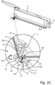
- Fig. 2C is a close-up view of the tipper arrangement 1.
- a single ejection arm 9 that is substantially L-shaped is shown being attached to a rear side 22 of the ejection board 7.
- the rear side 22 faces towards the front 10 of the tipper body 3, in the direction of the vehicle cab 4, at least in the initial position of the ejection board 7.
- the ejection board 7 is mechanically connected to a first end portion 21 of the at least one ejection arm 9.
- the first end portion 21 is on one end of the ejection arm with respect to the pivot point defining the pivot axis 15.
- the ejection arm 9 further comprises a second end portion 37 which provides a mechanical contact between the at least one ejection arm 9 and the respective stopper element 13.
- the second end portion 37 is on the opposite end of the ejection arm 9 with respect to the pivot axis 15. This means that if the second end 37 is pushed downwards, i.e., away from the underside 23 of the tipper body 3, the ejection arm 9 rotates clockwise in fig. 2C as indicated by the directional arrow 26 about the pivot axis 15. This rotation causes a displacement of the ejection arm 9 from its initial position P1 indicated in dashed lines 28 to a rotationally displaced position P2. Since the ejection board 7 is attached to the first end portion 21, the ejection board 7 is tilted towards the rear 17 of the tipper body to move stuck material A towards the rear 17.
- the spring 11 or torsion bar is biased between the ejection arm 9 and the tipper body 3. More specifically, the spring 11 is arranged under the tipper body biased between the second end portion 37 the at least one ejection arm 9 and the underside 23 of the tipper body 3.
- the spring in the initial position P1 of the ejection arm 9, the spring is compressed between the side 23 of the tipper body and the second end portion 37 of the ejection arm 9.
- the tipper body in is its horizontal portion, the second end portion 37 is in contact with the stopper element preventing a rotation of the ejection arm 9 about the pivot axis 15. Consequently, the spring 11 is kept biased, or compressed, until the contact between the second end portion 37 and the stopper element 13 is lost.
- the pressure between the second end portion 37 and the stopper element 13 reduces which allows the spring to decompress.
- the spring action push the second end portion 37 of the at least one ejection arm 9 away from the underside 23 of the tipper body 3 and cause the rotation of the ejection arm about the pivot axis 15.
- the spring 11 or torsion bar is attached to the underside 23 of the tipper body 3.
- the attachment is mechanical and is made by for example bolting or welding.
- a spring 11 has a fixed end 25 attached to the tipper body 3 and a free end 27 that push on the ejection arm 9.
- the free end 27 may lose contact with the ejection arm 9 during an unladen cycle when the ejection arm 9 has rotated through a sufficiently large rotation angle.
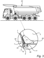
- Fig. 3 is a perspective view of the tipper arrangement 1 installed in the tipper body 3.
- the ejection arm 9 is attached to the tipper body 3 by an axle 33 that allow for the ejection arm 9 to rotate about the rotation axis 15.
- a bushing or a bearing arrangement of the axle 33 may provide for the rotation of the ejection arm 9 about teh axis 15.
- the axle 33 may be fixedly attached to the tipper body and the ejection arm 9 is rotatable with respect to the axle 33.
- the axle 33 may be welded or bolted to the tipper body 3, and the axle may be fitted through holes 36 in the ejection arm 9 having slightly larger diameter than the diameter of the axle 33.
- the axle 33 may
- the axle 33 may be fixedly attached to the ejection arm 9 while being rotatable about the axis 15 with respect to the tipper body 3.
- the axle 33 may be welded or bolted to the ejection arm 9.
- the axle 33 may be fitted through holes in attachment brackets of the tipper body 3 having slightly larger diameter than the diameter of the axle 33.
- the ejector board 7 may be plate shaped and be part of a headboard of the tipper body.
- the tipper body 3 comprises a through-hole 40 for each ejector arm through which the receptive at least one ejector arm 9 is arranged.
- Fig. 4A is a perspective view of the ejector board 7 being attached to the second portions 21a, 21b of respective ejector arms 9a, 9b.
- An axle 33 is coupled to the ejector arms 9a and 9b to form a common pivot axis 15 for the ejector arms 9a, 9b.
- the two ejector arms 9a, 9b are attached to opposite edge portions 31, 35 of the ejector board.
- two ejector arms 9a, 9b are attached to the ejector board 7 so that they are closer to the respective side edge that they are to each other.
- the edges portions 31 and 35 are on either side of the ejector board 7 along the width W.
- the ejector board 7 has dimensions being a width W and a height h, and thickness t.
- the width W is in the side-to-side direction of the tipper body, along a transverse axis of the vehicle 100 when the tipper arrangement is operationally installed in a vehicle 100.
- the height h is perpendicular to the width W, and the smallest dimension of the ejector board 7 is the thickness t.
- the thickness t is substantially smaller than the height h and width W.
- the ejector board 7 is relatively planar, or plate shaped.
- the ejector board 7 reach from side-to-side of the front 10 of the tipper body 3.
- the width W of the ejector board 7 may be only slightly smaller than the width of the tipper body 3 so that ejector board 7 fits inside the width of the tipper body 3.
- the height h of the ejector board 7 reach from the bottom 29 of the tipper body 3 to at least midway to the upper edge of the tipper body 3. In a further example, the ejector board 7 reaches from the bottom 29 of the tipper body 3 to about one third towards the upper edge 42 of the tipper body 3.
- the first portion 21, 21a, 21b of the ejector arm 9, 9a, 9b, may be welded or bolted to the ejector board 7.
- Fig. 4B is a perspective view of a further example where a single ejector arm 9 is attached to the ejector board 7. It is envisaged that two or more ejector arms 9 are possible and within possible developments of the preset disclosure.
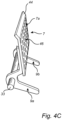
- Fig. 4C is a further perspective view of a further example where the ejector board 7 comprises an upper lip 44 that bends at an angle from the otherwise planar main body 7a of the ejector board 7.
- the lip 44 bends towards the front of the tipper body 3 to prevent material from falling in behind the ejector board 7.
- the ejector boards described herein may be perforated.
- the ejector board comprises a matrix of through-holes 46 reaching through the thickness t of the ejector board 7.
- the entire ejector board may be perforated, that is the matrix may cover the entire ejector board.
- the ejector arms and ejector boards presented herein are preferably made from a strong material such as a metal, e.g., steel or so-called Hardox ® steel (SSAB).
- the spring is also preferably made from e.g., steel.
- the tipper arrangement 1, comprising two ejection arms 9a-b being substantially L-shaped with a second portion 37 of the L-shaped ejector arm reaching outside and to the underside of the tipper body 3, and a first portion 21 of the L-shaped ejector arm reaching inside the tipper body 3 where it is attached to the ejector body 7 being a headboard of the tipper body.
- the L-shaped ejector arms 9a-b have a common pivot axis where the first portion and the second portion of the substantially L-shaped ejector arm come together at an angle.
- the actuator is a spring 11 or a torsion bar, wherein the spring action is configured to push the first end portion of the at least one ejection arm 9 away from the underside of the tipper body 3 to cause the rotation of the ejector arms.
- the mechanical contact with the stopper element 13 prevents rotation of the at least one ejection arm 9 under the spring action, and when the tipper body 3 is tilted for an unloading action, the mechanical contact between the stopper element and the ejector arm is lost so that the spring acts on the ejector arm 9a-b to cause a rotation about the pivot axis 15 and thereby a motion of the ejector board towards the rear of the tipper body 3 to expel load from the tipper body.
- the actuator may be one of, or may be assisted by one of a pneumatic actuator, a hydraulic actuator, and an electric actuator.
- the actuator is activated in response to that the at least one ejection arm 9 loses contact with the stopper element 13.
- Relative terms such as “below” or “above” or “upper” or “lower” or “horizontal” or “vertical” may be used herein to describe a relationship of one element to another element as illustrated in the Figures. It will be understood that these terms and those discussed above are intended to encompass different orientations of the device in addition to the orientation depicted in the Figures. It will be understood that when an element is referred to as being “connected” or “coupled” to another element, it can be directly connected or coupled to the other element, or intervening elements may be present. In contrast, when an element is referred to as being “directly connected” or “directly coupled” to another element, there are no intervening elements present.
Landscapes
- Engineering & Computer Science (AREA)
- Transportation (AREA)
- Mechanical Engineering (AREA)
- Cleaning Of Streets, Tracks, Or Beaches (AREA)
Abstract
Description
- The disclosure relates generally to a tipper arrangement for a vehicle. In particular aspects, the disclosure relates to deadweight reduction in tippers. The disclosure can be applied in heavy-duty vehicles, such as trucks, buses, and construction equipment. Although the disclosure may be described with respect to a particular vehicle, the disclosure is not restricted to any particular vehicle.
- For tipper vehicles it is of importance that as much as possible of the load is unloaded when intended. It is often observed that after tipping, a portion of load often gets stuck due the nature of design of tipper structures.
- This stuck material, or residual load, cause so-called deadweight which effectively reduces the amount of material that can be loaded in subsequent transport cycles. This requires additional time consuming and environmentally disadvantageous transport cycles to transport a given amount of load. In many applications, such as heavy construction and mining trucks, payload matters a lot to the efficiency of an overall fleet operation and stuck material should be avoided.
- According to a first aspect of the disclosure, there is provided a tipper arrangement for a vehicle, comprising: a tipper body for carrying a load; a movable ejection board mechanically attached to at least one an ejection arm at a front of the tipper body inside the tipper body, the at least one ejection arm is pivotable attached with respect to the tipper body and extend to below the tipper body; an actuator configured to rotate the at least one ejection arm from an initial position in which the at least one ejection arm is in mechanical contact with a stopper element below the tipper body that prevent rotation of the at least one ejection arm, to a rotated position in which the at least one ejection arm is rotated about a pivot axis to cause a motion of the ejector board towards the rear of the tipper body to expel load from the front of the tipper body.
- The first aspect of the disclosure may seek to provide a simple yet robust way of reducing the amount of residual deadweight that is left in the tipper body after a tipping action. Furthermore, the first aspect of the disclosure may provide for a mechanical solution with reduced risk of failure due to its robustness.
- According to one example, when the tipper body is in a normal loading position the at least one ejection arm is in mechanical contact with the stopper element. A technical benefit may be that the stopper element provides for a robust way of preventing the ejection arm from rotating when the tipper body is in a normal loading position. The normal loading position may be that the tipper body is substantially horizontal so that load maintains by gravity in the tipper body.
- In one example, the ejection board may be mechanically attached to a first end portion of the at least one ejection arm on one side of the pivot point of the at least one ejection arm and the mechanical contact between the at least one ejection arm and the stopper element is on a second end portion of the at least one ejection arm on the opposite end of the ejection arm with respect to the pivot point.
- Hereby, the ejection arm is used as a relatively longer lever to provide a higher ejection force on the residual load in the tipper body via the ejection board.
- In one example, the at least one ejection arm may be substantially L-shaped. This advantageously provides for arranging the second end portion under the tipper body where it can be packaged in a compact way.
- In one example, the actuator is a resilient actuator such as a spring or a torsion bar. A resilient actuator advantageously provides for a simple and robust way of timely apply a force on the ejection arm as the tipper body moves from a normal loading position to a tipping position to expel load from the front of the tipper body.
- In one example, the resilient actuator may be biased between the second end portion of the at least one ejection arm and the underside of the tipper body, wherein the spring action push the second end portion of the at least one ejection arm away from the underside of the tipper body. The underside is the side opposite, and vertically, from the side where the load is located. The underside faces the chassis of the vehicle.
- In one example, a fixed end of the resilient actuator may be attached to the tipper body and the other end is a free end that push on the ejection arm. The fixed end may reduce the risk of losing the resilient actuator, and the free end may ensure that the resilient actuator force is fully utilized, i.e., the free does not pull the ejector arm back after release.
- In one example, the actuator may be assisted by one of a pneumatic actuator, a hydraulic actuator, and an electric actuator. For example, the assisting actuator may be activated in response to that the at least one ejection arm loses contact with the stopper element.
- In one example, the ejector board may reach from side-to-side of the front of the tipper body. Hereby, more residual load can be expelled from the tipper body.
- In one example, the ejector board may reach from the bottom of the tipper body to at least midway to the upper edge of the tipper body. Again, in this way, an increased amount of residual load can be expelled from the tipper body.
- In one example, the ejector board reach from the bottom of the tipper body to about one third towards the upper edge of the tipper body.
- In one example, the ejector board is perforated. Perforations can act as passage for stuck material between the tipper body headboard and the ejector board, thus enabling for ejecting increased amounts of residual load. Furthermore, a perforated ejector board may reduce the weight of the ejector boar and consequently reduces the effort on the spring to increase its lifetime.
- In one example, the ejector arm may pivotably attached to the tipper body. This may provide a convenient attachment location for the ejector arm.
- In one example, the tipper arrangement may comprise two ejector arms attached to opposite edge portions of the ejector board. A benefit is that two ejector arms provide a more stable and even activation force on the ejector board. Furthermore, with one spring per ejector arm, a higher total force can be provided which may allow for more efficient expulsion of residual load. The ejector arms advantageously have a common pivot axis.
- In one example, the ejector board may be a plate shaped headboard of the tipper body.
- In one example, and to provide for efficient installation and operation, the tipper body may comprise a through-hole for each ejector arm through which the receptive at least one ejector arm is arranged.
- In one example, the tipper arrangement may comprise two ejection arms being substantially L-shaped with a first end portion of the L-shaped ejector arm reaching inside the tipper body where it is attached to the ejector body being a headboard of the tipper body, and a second end portion of the L-shaped ejector arm reaching outside and to the underside of the tipper body, and, wherein L-shaped ejector arms have a common pivot axis where the first portion and the second portion of the substantially L-shaped ejector arm come together at an angle, wherein the actuator is a spring or a torsion bar, wherein the spring action is configured to push the second end portion of the at least one ejection arm away from the underside of the tipper body to cause the rotation of the ejector arms, wherein, in the an initial position of the ejector arm when the tipper body is in a neutral position, the mechanical contact with the stopper element prevents rotation of the at least one ejection arm under the spring action, and wherein when the tipper body is tilted for an unloading action, the mechanical contact between the stopper element and the ejector arm is lost so that the spring or torsion bar acts on the ejector arm to cause a rotation about the pivot axis and thereby a motion of the ejector board towards the rear of the tipper body to expel load from the tipper body.
- According to a second aspect of the disclosure, there is provided a vehicle comprising a tipper body and the tipper arrangement according to the first aspect.
- The above aspects, accompanying claims, and/or examples disclosed herein above and later below may be suitably combined with each other as would be apparent to anyone of ordinary skill in the art.
- Additional features and advantages are disclosed in the following description, claims, and drawings, and in part will be readily apparent therefrom to those skilled in the art or recognized by practicing the disclosure as described herein. There are also disclosed herein control units, computer readable media, and computer program products associated with the above discussed technical benefits.
- With reference to the appended drawings, below follows a more detailed description of aspects of the disclosure cited as examples.
-
FIG. 1 is an exemplary prior art truck with a tipper structure; -
FIG. 2A is an exemplary is an exemplary vehicle with a tipper arrangement and a tipper body in an initial position; -
FIG. 2B is an exemplary is an exemplary vehicle with a tipper arrangement and a tipper body in an unladen position; -
FIG. 2C is a close-up view of an exemplary tipper arrangement infig. 2A andfig. 2C ; -
FIG. 3 is a perspective view of an example tipper arrangement installed in a tipper body; -
FIG. 4A is a perspective view of an example ejector board attached to two ejector arms; -
FIG. 4B is a perspective view of an example ejector board attached to on ejector arm; and -
FIG. 4C is a perspective view of an example perforated ejector arm attached to ejector arms. - Aspects set forth below represent the necessary information to enable those skilled in the art to practice the disclosure.
-
FIG. 1 illustrates a typical priorart tipper truck 1000, or sometimes referred to as dumping truck or dump trailer, having atipper structure 1002 for carrying a load, typically for construction or mining such as macadam, sand, coal, dirt, to mention a few examples. During an unladen cycle wherecargo 5 should be unloaded from thetipper structure 1002, it often occurs thatmaterial 5 gets stuck on thetipper structure 1002, typically in front area A of thetipper structure 1002 but also flat on the bottom surface in area B of thetipper structure 1002. This stuck material leads to deadweight in subsequent laden cycles since the tipper capacity is reduced for payload. The examples discussed herein aim to at least alleviate this problem. -
FIG. 2A is anexemplary vehicle 100 according to one example. The vehicle comprises atipper arrangement 1 and atipper body 3 for carrying aload 5, here only shown in the front region A of thetipper body 3. - The
tipper arrangement 1 comprises amovable ejection board 7 mechanically attached to at least one anejection arm 9 at thefront 10 of the tipper body inside the tipper body. The front of the tipper body is at the end of the tipper body facing towards thecab 4 of the vehicle in the forward driving direction of thevehicle 100. The at least oneejection arm 9 is pivotable attached with respect to thetipper body 3 and extend to below thetipper body 3 towards achassis 8 of thevehicle 100. Below thetipper body 3 is here between, e.g., sandwiched between thetipper body 3 and thechassis 8. - Further, the
tipper arrangement 1 comprises anactuator 11 provided as aspring 11 or a torsion bar, configured to rotate the at least oneejection arm 9 from an initial position, shown infig. 2A , in which the at least oneejection arm 9 is in mechanical contact with astopper element 13, better seen infig. 2B , below thetipper body 3 that prevent rotation of the at least one ejection arm, to a rotated position, better seen infig. 2B , in which the at least oneejection arm 9 is rotated about apivot axis 15 to cause a motion of theejector board 7 towards the rear 17 of the tipper body to expel load from thefront 10 of thetipper body 3. In the initial position of the ejection arm, thetipper body 3 is in a normal loading position shown infig. 2A . Thus, thetipper body 3 is in a generally horizontal orientation so that load maintains in thetipper body 3. - The
actuator 11 is herein depicted as a spring, but may equally well be replaced by a torsion bar performing the same function as thespring 11, thus providing a spring force that cause rotation of theejection arm 9. -
Fig. 2C is a close-up view of thetipper arrangement 1. Here, in this side-view asingle ejection arm 9 that is substantially L-shaped is shown being attached to arear side 22 of theejection board 7. Therear side 22 faces towards thefront 10 of thetipper body 3, in the direction of thevehicle cab 4, at least in the initial position of theejection board 7. More specifically, theejection board 7 is mechanically connected to afirst end portion 21 of the at least oneejection arm 9. Thefirst end portion 21 is on one end of the ejection arm with respect to the pivot point defining thepivot axis 15. Theejection arm 9 further comprises asecond end portion 37 which provides a mechanical contact between the at least oneejection arm 9 and therespective stopper element 13. Thesecond end portion 37 is on the opposite end of theejection arm 9 with respect to thepivot axis 15. This means that if thesecond end 37 is pushed downwards, i.e., away from theunderside 23 of thetipper body 3, theejection arm 9 rotates clockwise infig. 2C as indicated by thedirectional arrow 26 about thepivot axis 15. This rotation causes a displacement of theejection arm 9 from its initial position P1 indicated in dashedlines 28 to a rotationally displaced position P2. Since theejection board 7 is attached to thefirst end portion 21, theejection board 7 is tilted towards the rear 17 of the tipper body to move stuck material A towards the rear 17. - The
spring 11 or torsion bar is biased between theejection arm 9 and thetipper body 3. More specifically, thespring 11 is arranged under the tipper body biased between thesecond end portion 37 the at least oneejection arm 9 and theunderside 23 of thetipper body 3. Thus, in the initial position P1 of theejection arm 9, the spring is compressed between theside 23 of the tipper body and thesecond end portion 37 of theejection arm 9. As long as the tipper body in is its horizontal portion, thesecond end portion 37 is in contact with the stopper element preventing a rotation of theejection arm 9 about thepivot axis 15. Consequently, thespring 11 is kept biased, or compressed, until the contact between thesecond end portion 37 and thestopper element 13 is lost. - When the
tipper body 3 is tilted i.e., due to a unladen cycle, the pressure between thesecond end portion 37 and thestopper element 13 reduces which allows the spring to decompress. The spring action push thesecond end portion 37 of the at least oneejection arm 9 away from theunderside 23 of thetipper body 3 and cause the rotation of the ejection arm about thepivot axis 15. - The
spring 11 or torsion bar is attached to theunderside 23 of thetipper body 3. The attachment is mechanical and is made by for example bolting or welding. In this case, aspring 11 has a fixed end 25 attached to thetipper body 3 and afree end 27 that push on theejection arm 9. Thefree end 27 may lose contact with theejection arm 9 during an unladen cycle when theejection arm 9 has rotated through a sufficiently large rotation angle. -
Fig. 3 is a perspective view of thetipper arrangement 1 installed in thetipper body 3. Theejection arm 9 is attached to thetipper body 3 by anaxle 33 that allow for theejection arm 9 to rotate about therotation axis 15. A bushing or a bearing arrangement of theaxle 33 may provide for the rotation of theejection arm 9 about tehaxis 15. Theaxle 33 may be fixedly attached to the tipper body and theejection arm 9 is rotatable with respect to theaxle 33. For example, theaxle 33 may be welded or bolted to thetipper body 3, and the axle may be fitted throughholes 36 in theejection arm 9 having slightly larger diameter than the diameter of theaxle 33. Furthermore, theaxle 33 may - Equally, the
axle 33 may be fixedly attached to theejection arm 9 while being rotatable about theaxis 15 with respect to thetipper body 3. Theaxle 33 may be welded or bolted to theejection arm 9. In this case, theaxle 33 may be fitted through holes in attachment brackets of thetipper body 3 having slightly larger diameter than the diameter of theaxle 33. Theejector board 7 may be plate shaped and be part of a headboard of the tipper body. - Furthermore, to allow the
ejector arm 9 to reach inside thetipper body 3 at the front 10, thetipper body 3 comprises a through-hole 40 for each ejector arm through which the receptive at least oneejector arm 9 is arranged. -
Fig. 4A is a perspective view of theejector board 7 being attached to thesecond portions respective ejector arms axle 33 is coupled to theejector arms common pivot axis 15 for theejector arms ejector arms opposite edge portions ejector arms ejector board 7 so that they are closer to the respective side edge that they are to each other. Theedges portions ejector board 7 along the width W. - The
ejector board 7 has dimensions being a width W and a height h, and thickness t. The width W is in the side-to-side direction of the tipper body, along a transverse axis of thevehicle 100 when the tipper arrangement is operationally installed in avehicle 100. The height h is perpendicular to the width W, and the smallest dimension of theejector board 7 is the thickness t. The thickness t is substantially smaller than the height h and width W. Further, theejector board 7 is relatively planar, or plate shaped. - With further reference to
fig. 3 , preferably, theejector board 7 reach from side-to-side of thefront 10 of thetipper body 3. In other words, the width W of theejector board 7 may be only slightly smaller than the width of thetipper body 3 so thatejector board 7 fits inside the width of thetipper body 3. - To further improve the ability for the
tipper arrangement 1 to eject residual material from the tipper body, the height h of theejector board 7 reach from the bottom 29 of thetipper body 3 to at least midway to the upper edge of thetipper body 3. In a further example, theejector board 7 reaches from the bottom 29 of thetipper body 3 to about one third towards theupper edge 42 of thetipper body 3. - The
first portion ejector arm ejector board 7. -
Fig. 4B is a perspective view of a further example where asingle ejector arm 9 is attached to theejector board 7. It is envisaged that two ormore ejector arms 9 are possible and within possible developments of the preset disclosure. -
Fig. 4C is a further perspective view of a further example where theejector board 7 comprises anupper lip 44 that bends at an angle from the otherwise planarmain body 7a of theejector board 7. Thelip 44 bends towards the front of thetipper body 3 to prevent material from falling in behind theejector board 7. - Furthermore, the ejector boards described herein may be perforated. Thus, the ejector board comprises a matrix of through-
holes 46 reaching through the thickness t of theejector board 7. The entire ejector board may be perforated, that is the matrix may cover the entire ejector board. - The ejector arms and ejector boards presented herein are preferably made from a strong material such as a metal, e.g., steel or so-called Hardox® steel (SSAB). The spring is also preferably made from e.g., steel.
- It is envisaged that the
tipper arrangement 1, comprising twoejection arms 9a-b being substantially L-shaped with asecond portion 37 of the L-shaped ejector arm reaching outside and to the underside of thetipper body 3, and afirst portion 21 of the L-shaped ejector arm reaching inside thetipper body 3 where it is attached to theejector body 7 being a headboard of the tipper body. The L-shapedejector arms 9a-b have a common pivot axis where the first portion and the second portion of the substantially L-shaped ejector arm come together at an angle. Further, in this example, the actuator is aspring 11 or a torsion bar, wherein the spring action is configured to push the first end portion of the at least oneejection arm 9 away from the underside of thetipper body 3 to cause the rotation of the ejector arms. In the initial position of the ejector arm when thetipper body 3 is in a neutral position, or loading, or horizontal position, the mechanical contact with thestopper element 13 prevents rotation of the at least oneejection arm 9 under the spring action, and when thetipper body 3 is tilted for an unloading action, the mechanical contact between the stopper element and the ejector arm is lost so that the spring acts on theejector arm 9a-b to cause a rotation about thepivot axis 15 and thereby a motion of the ejector board towards the rear of thetipper body 3 to expel load from the tipper body. - It is envisaged that the actuator may be one of, or may be assisted by one of a pneumatic actuator, a hydraulic actuator, and an electric actuator. In such arrangements, the actuator is activated in response to that the at least one
ejection arm 9 loses contact with thestopper element 13. - The terminology used herein is for the purpose of describing particular aspects only and is not intended to be limiting of the disclosure. As used herein, the singular forms "a," "an," and "the" are intended to include the plural forms as well, unless the context clearly indicates otherwise. As used herein, the term "and/or" includes any and all combinations of one or more of the associated listed items. It will be further understood that the terms "comprises," "comprising," "includes," and/or "including" when used herein specify the presence of stated features, integers, steps, operations, elements, and/or components, but do not preclude the presence or addition of one or more other features, integers, steps, operations, elements, components, and/or groups thereof.
- It will be understood that, although the terms first, second, etc., may be used herein to describe various elements, these elements should not be limited by these terms. These terms are only used to distinguish one element from another. For example, a first element could be termed a second element, and, similarly, a second element could be termed a first element without departing from the scope of the present disclosure.
- Relative terms such as "below" or "above" or "upper" or "lower" or "horizontal" or "vertical" may be used herein to describe a relationship of one element to another element as illustrated in the Figures. It will be understood that these terms and those discussed above are intended to encompass different orientations of the device in addition to the orientation depicted in the Figures. It will be understood that when an element is referred to as being "connected" or "coupled" to another element, it can be directly connected or coupled to the other element, or intervening elements may be present. In contrast, when an element is referred to as being "directly connected" or "directly coupled" to another element, there are no intervening elements present.
- Unless otherwise defined, all terms (including technical and scientific terms) used herein have the same meaning as commonly understood by one of ordinary skill in the art to which this disclosure belongs. It will be further understood that terms used herein should be interpreted as having a meaning consistent with their meaning in the context of this specification and the relevant art and will not be interpreted in an idealized or overly formal sense unless expressly so defined herein.
- It is to be understood that the present disclosure is not limited to the aspects described above and illustrated in the drawings; rather, the skilled person will recognize that many changes and modifications may be made within the scope of the present disclosure and appended claims. In the drawings and specification, there have been disclosed aspects for purposes of illustration only and not for purposes of limitation, the scope of the inventive concepts being set forth in the following claims.
Claims (15)
- A tipper arrangement (1) for a vehicle, comprising:a tipper body (3) for carrying a load (5/A);a movable ejection board (7) mechanically attached to at least one an ejection arm (9) at a front (10) of the tipper body inside the tipper body, the at least one ejection arm (9) is pivotable attached with respect to the tipper body (3) and extend to below the tipper body;an actuator (11) configured to rotate the at least one ejection arm (9) from an initial position in which the at least one ejection arm (9) is in mechanical contact with a stopper element (13) below the tipper body that prevent rotation of the at least one ejection arm (9), to a rotated position in which the at least one ejection arm (9) is rotated about a pivot axis (15) to cause a motion of the ejector board (7) towards the rear (17) of the tipper body to expel load from the front of the tipper body.
- The tipper arrangement (1) of claim 1, wherein, when the tipper body (3) is in a normal loading position the at least one ejection arm (9) is in mechanical contact with the stopper element (13).
- The tipper arrangement (1) of any of claims 1-2, wherein the ejection board (7) is mechanically attached to a first end portion (21) of the at least one ejection arm (9) on one side of the pivot point of the at least one ejection arm (9) and the mechanical contact between the at least one ejection arm (9) and the stopper element is on a second end portion (37) of the at least one ejection arm (9) on the opposite end of the ejection arm with respect to the pivot point.
- The tipper arrangement (1) of any of claims 1-3, the at least one ejection arm (9) being substantially L-shaped.
- The tipper arrangement (1) of any of claims 1-3, wherein the actuator (11) is a resilient actuator.
- The tipper arrangement (1) of claim 5, wherein the resilient actuator is biased between a second end portion (37) the at least one ejection arm (9) and the underside (23) of the tipper body (3), wherein the resilient actuator action push the second end portion (37) of the at least one ejection arm (9) away from the underside (23) of the tipper body (3).
- The tipper arrangement (1) of any one of claims 5 and 6, wherein a fixed end (25) of the resilient actuator is attached to the tipper body (3) and the other end is a free end (27) that push on the ejection arm.
- The tipper arrangement (1) of any of claims 1-7, the ejector board (7) reach from side-to-side of the front (10) of the tipper body (3).
- The tipper arrangement (1) of any of claims 1-8, wherein the ejector board reach from the bottom (29) of the tipper body (3) to at least midway to the upper edge of the tipper body.
- The tipper arrangement (1) of any of claims 1-9, the ejector board reach from the bottom of the tipper body (3) to about one third towards the upper edge of the tipper body.
- The tipper arrangement (1) of any of claims 1-10, wherein the ejector arm (9) is pivotably attached to the tipper body.
- The tipper arrangement (1) of any of claims 1-11, comprising two ejector arms attached to opposite edge portions (31, 35) of the ejector board.
- The tipper arrangement (1) of any of claims 1-12, the ejector board is perforated.
- The tipper arrangement (1) of claim 1, comprising two ejection arms (9a-b) being substantially L-shaped with a first end portion (21) of the L-shaped ejector arm reaching inside the tipper body (3) where it is attached to the ejector body (7) being a headboard of the tipper body, and a second end portion (37) of the L-shaped ejector arm reaching outside and to the underside of the tipper body (3), and,wherein L-shaped ejector arms (9a-b) have a common pivot axis where the first portion and the second portion of the substantially L-shaped ejector arm come together at an angle,wherein the actuator is a spring (11) or a torsion bar, wherein the spring action is configured to push the second end portion of the at least one ejection arm (9) away from the underside of the tipper body (3) to cause the rotation of the ejector arms,wherein, in the an initial position of the ejector arm when the tipper body (3) is in a neutral position, the mechanical contact with the stopper element (13) prevents rotation of the at least one ejection arm (9) under the spring action, and wherein when the tipper body (3) is tilted for an unloading action, the mechanical contact between the stopper element and the ejector arm is lost so that the spring acts on the ejector arm (9a-b) to cause a rotation about the pivot axis (15) and thereby a motion of the ejector board towards the rear of the tipper body (3) to expel load from the tipper body.
- A vehicle (100) comprising a tipper body (3) and the tipper arrangement (1) according to any of claims 1-19.
Priority Applications (2)
| Application Number | Priority Date | Filing Date | Title |
|---|---|---|---|
| EP22212743.3A EP4385817B1 (en) | 2022-12-12 | 2022-12-12 | Deadweight reduction in tippers |
| US18/517,628 US20240190324A1 (en) | 2022-12-12 | 2023-11-22 | Deadweight reduction in tippers |
Applications Claiming Priority (1)
| Application Number | Priority Date | Filing Date | Title |
|---|---|---|---|
| EP22212743.3A EP4385817B1 (en) | 2022-12-12 | 2022-12-12 | Deadweight reduction in tippers |
Publications (2)
| Publication Number | Publication Date |
|---|---|
| EP4385817A1 true EP4385817A1 (en) | 2024-06-19 |
| EP4385817B1 EP4385817B1 (en) | 2025-07-09 |
Family
ID=84488213
Family Applications (1)
| Application Number | Title | Priority Date | Filing Date |
|---|---|---|---|
| EP22212743.3A Active EP4385817B1 (en) | 2022-12-12 | 2022-12-12 | Deadweight reduction in tippers |
Country Status (2)
| Country | Link |
|---|---|
| US (1) | US20240190324A1 (en) |
| EP (1) | EP4385817B1 (en) |
Citations (3)
| Publication number | Priority date | Publication date | Assignee | Title |
|---|---|---|---|---|
| FR2140849A5 (en) * | 1971-06-09 | 1973-01-19 | Semat | |
| US6764138B1 (en) * | 2002-02-28 | 2004-07-20 | David A. Johnas | Automatic actuating baffle for a dump box |
| FR2944488A1 (en) * | 2009-04-20 | 2010-10-22 | Ornaise De Chaudronnerie Carro | Autonomous loading bed for e.g. trailer, has pushing units pushing raising wall between loading position in which lower edge rests on bottom and unloading position in which lower edge is remote from bottom, and raises and pushes back load |
-
2022
- 2022-12-12 EP EP22212743.3A patent/EP4385817B1/en active Active
-
2023
- 2023-11-22 US US18/517,628 patent/US20240190324A1/en active Pending
Patent Citations (3)
| Publication number | Priority date | Publication date | Assignee | Title |
|---|---|---|---|---|
| FR2140849A5 (en) * | 1971-06-09 | 1973-01-19 | Semat | |
| US6764138B1 (en) * | 2002-02-28 | 2004-07-20 | David A. Johnas | Automatic actuating baffle for a dump box |
| FR2944488A1 (en) * | 2009-04-20 | 2010-10-22 | Ornaise De Chaudronnerie Carro | Autonomous loading bed for e.g. trailer, has pushing units pushing raising wall between loading position in which lower edge rests on bottom and unloading position in which lower edge is remote from bottom, and raises and pushes back load |
Also Published As
| Publication number | Publication date |
|---|---|
| US20240190324A1 (en) | 2024-06-13 |
| EP4385817B1 (en) | 2025-07-09 |
Similar Documents
| Publication | Publication Date | Title |
|---|---|---|
| EP1188612B1 (en) | Improvements in and relating to tipping trailers | |
| JP2015116920A (en) | Dump device loadable on truck | |
| CN113771721B (en) | Side-turning type self-discharging semi-trailer carriage | |
| US8333543B1 (en) | Mining scoop material ejection retrieval system | |
| CN105283352B (en) | Foldable backboard, the loader(-mounted) shovel with the foldable backboard and the vehicle with the loader(-mounted) shovel | |
| EP4385817B1 (en) | Deadweight reduction in tippers | |
| CN110203234B (en) | Top cover device and railway wagon | |
| US9381846B2 (en) | Haul bodies and related apparatus | |
| CN101495360B (en) | mechanical tailgate | |
| US8079646B2 (en) | Vehicle or trailer | |
| CN100462254C (en) | Walkable rollover dump truck | |
| CN210337697U (en) | A tailgate actively opening type cargo box and a mining dump truck using the same | |
| KR102195801B1 (en) | Mounted agricultural product dump carrier | |
| CN213861985U (en) | Dumper with double-side turnover locking bottom plate | |
| EP2928725B1 (en) | Vehicle or trailer with dropping floor | |
| CN219790001U (en) | Skeleton transportation semitrailer crawler back-pushing type dump truck | |
| JP4159851B2 (en) | Container loading and unloading vehicle | |
| JP6814679B2 (en) | Freight car | |
| JP6676797B2 (en) | Lorry | |
| CN216139898U (en) | Dumper with carriage shaking function | |
| CN222988048U (en) | Novel dumper container overturning mechanism | |
| CN213007793U (en) | Dumper transportation asphalt raw material anti-falling device | |
| CN200954795Y (en) | Self-unloading vehicle car for mine use | |
| CN1876436A (en) | Self-dumping vehicle with bottom plate capable of being overturned from both sides | |
| CN213920798U (en) | Bottom plate unilateral flip locking dump truck |
Legal Events
| Date | Code | Title | Description |
|---|---|---|---|
| PUAI | Public reference made under article 153(3) epc to a published international application that has entered the european phase |
Free format text: ORIGINAL CODE: 0009012 |
|
| STAA | Information on the status of an ep patent application or granted ep patent |
Free format text: STATUS: THE APPLICATION HAS BEEN PUBLISHED |
|
| AK | Designated contracting states |
Kind code of ref document: A1 Designated state(s): AL AT BE BG CH CY CZ DE DK EE ES FI FR GB GR HR HU IE IS IT LI LT LU LV MC ME MK MT NL NO PL PT RO RS SE SI SK SM TR |
|
| STAA | Information on the status of an ep patent application or granted ep patent |
Free format text: STATUS: REQUEST FOR EXAMINATION WAS MADE |
|
| 17P | Request for examination filed |
Effective date: 20241114 |
|
| RBV | Designated contracting states (corrected) |
Designated state(s): AL AT BE BG CH CY CZ DE DK EE ES FI FR GB GR HR HU IE IS IT LI LT LU LV MC ME MK MT NL NO PL PT RO RS SE SI SK SM TR |
|
| GRAP | Despatch of communication of intention to grant a patent |
Free format text: ORIGINAL CODE: EPIDOSNIGR1 |
|
| STAA | Information on the status of an ep patent application or granted ep patent |
Free format text: STATUS: GRANT OF PATENT IS INTENDED |
|
| INTG | Intention to grant announced |
Effective date: 20250217 |
|
| GRAS | Grant fee paid |
Free format text: ORIGINAL CODE: EPIDOSNIGR3 |
|
| GRAA | (expected) grant |
Free format text: ORIGINAL CODE: 0009210 |
|
| STAA | Information on the status of an ep patent application or granted ep patent |
Free format text: STATUS: THE PATENT HAS BEEN GRANTED |
|
| AK | Designated contracting states |
Kind code of ref document: B1 Designated state(s): AL AT BE BG CH CY CZ DE DK EE ES FI FR GB GR HR HU IE IS IT LI LT LU LV MC ME MK MT NL NO PL PT RO RS SE SI SK SM TR |
|
| REG | Reference to a national code |
Ref country code: GB Ref legal event code: FG4D |
|
| REG | Reference to a national code |
Ref country code: CH Ref legal event code: EP |
|
| REG | Reference to a national code |
Ref country code: IE Ref legal event code: FG4D |
|
| REG | Reference to a national code |
Ref country code: DE Ref legal event code: R096 Ref document number: 602022017266 Country of ref document: DE |
|
| REG | Reference to a national code |
Ref country code: NL Ref legal event code: MP Effective date: 20250709 |
|
| PG25 | Lapsed in a contracting state [announced via postgrant information from national office to epo] |
Ref country code: PT Free format text: LAPSE BECAUSE OF FAILURE TO SUBMIT A TRANSLATION OF THE DESCRIPTION OR TO PAY THE FEE WITHIN THE PRESCRIBED TIME-LIMIT Effective date: 20251110 |
|
| PG25 | Lapsed in a contracting state [announced via postgrant information from national office to epo] |
Ref country code: NL Free format text: LAPSE BECAUSE OF FAILURE TO SUBMIT A TRANSLATION OF THE DESCRIPTION OR TO PAY THE FEE WITHIN THE PRESCRIBED TIME-LIMIT Effective date: 20250709 |
|
| REG | Reference to a national code |
Ref country code: AT Ref legal event code: MK05 Ref document number: 1811582 Country of ref document: AT Kind code of ref document: T Effective date: 20250709 |
|
| PG25 | Lapsed in a contracting state [announced via postgrant information from national office to epo] |
Ref country code: IS Free format text: LAPSE BECAUSE OF FAILURE TO SUBMIT A TRANSLATION OF THE DESCRIPTION OR TO PAY THE FEE WITHIN THE PRESCRIBED TIME-LIMIT Effective date: 20251109 |
|
| PG25 | Lapsed in a contracting state [announced via postgrant information from national office to epo] |
Ref country code: NO Free format text: LAPSE BECAUSE OF FAILURE TO SUBMIT A TRANSLATION OF THE DESCRIPTION OR TO PAY THE FEE WITHIN THE PRESCRIBED TIME-LIMIT Effective date: 20251009 |
|
| REG | Reference to a national code |
Ref country code: LT Ref legal event code: MG9D |
|
| PG25 | Lapsed in a contracting state [announced via postgrant information from national office to epo] |
Ref country code: AT Free format text: LAPSE BECAUSE OF FAILURE TO SUBMIT A TRANSLATION OF THE DESCRIPTION OR TO PAY THE FEE WITHIN THE PRESCRIBED TIME-LIMIT Effective date: 20250709 |
|
| PG25 | Lapsed in a contracting state [announced via postgrant information from national office to epo] |
Ref country code: FI Free format text: LAPSE BECAUSE OF FAILURE TO SUBMIT A TRANSLATION OF THE DESCRIPTION OR TO PAY THE FEE WITHIN THE PRESCRIBED TIME-LIMIT Effective date: 20250709 |
|
| PG25 | Lapsed in a contracting state [announced via postgrant information from national office to epo] |
Ref country code: HR Free format text: LAPSE BECAUSE OF FAILURE TO SUBMIT A TRANSLATION OF THE DESCRIPTION OR TO PAY THE FEE WITHIN THE PRESCRIBED TIME-LIMIT Effective date: 20250709 |
|
| PG25 | Lapsed in a contracting state [announced via postgrant information from national office to epo] |
Ref country code: GR Free format text: LAPSE BECAUSE OF FAILURE TO SUBMIT A TRANSLATION OF THE DESCRIPTION OR TO PAY THE FEE WITHIN THE PRESCRIBED TIME-LIMIT Effective date: 20251010 |
|
| PG25 | Lapsed in a contracting state [announced via postgrant information from national office to epo] |
Ref country code: SE Free format text: LAPSE BECAUSE OF FAILURE TO SUBMIT A TRANSLATION OF THE DESCRIPTION OR TO PAY THE FEE WITHIN THE PRESCRIBED TIME-LIMIT Effective date: 20250709 |
|
| PG25 | Lapsed in a contracting state [announced via postgrant information from national office to epo] |
Ref country code: LV Free format text: LAPSE BECAUSE OF FAILURE TO SUBMIT A TRANSLATION OF THE DESCRIPTION OR TO PAY THE FEE WITHIN THE PRESCRIBED TIME-LIMIT Effective date: 20250709 |
|
| PG25 | Lapsed in a contracting state [announced via postgrant information from national office to epo] |
Ref country code: PL Free format text: LAPSE BECAUSE OF FAILURE TO SUBMIT A TRANSLATION OF THE DESCRIPTION OR TO PAY THE FEE WITHIN THE PRESCRIBED TIME-LIMIT Effective date: 20250709 Ref country code: BG Free format text: LAPSE BECAUSE OF FAILURE TO SUBMIT A TRANSLATION OF THE DESCRIPTION OR TO PAY THE FEE WITHIN THE PRESCRIBED TIME-LIMIT Effective date: 20250709 |
|
| PG25 | Lapsed in a contracting state [announced via postgrant information from national office to epo] |
Ref country code: RS Free format text: LAPSE BECAUSE OF FAILURE TO SUBMIT A TRANSLATION OF THE DESCRIPTION OR TO PAY THE FEE WITHIN THE PRESCRIBED TIME-LIMIT Effective date: 20251009 |
|
| PG25 | Lapsed in a contracting state [announced via postgrant information from national office to epo] |
Ref country code: ES Free format text: LAPSE BECAUSE OF FAILURE TO SUBMIT A TRANSLATION OF THE DESCRIPTION OR TO PAY THE FEE WITHIN THE PRESCRIBED TIME-LIMIT Effective date: 20250709 |
|
| PG25 | Lapsed in a contracting state [announced via postgrant information from national office to epo] |
Ref country code: RO Free format text: LAPSE BECAUSE OF FAILURE TO SUBMIT A TRANSLATION OF THE DESCRIPTION OR TO PAY THE FEE WITHIN THE PRESCRIBED TIME-LIMIT Effective date: 20250709 |
|
| PG25 | Lapsed in a contracting state [announced via postgrant information from national office to epo] |
Ref country code: SM Free format text: LAPSE BECAUSE OF FAILURE TO SUBMIT A TRANSLATION OF THE DESCRIPTION OR TO PAY THE FEE WITHIN THE PRESCRIBED TIME-LIMIT Effective date: 20250709 |
|
| PG25 | Lapsed in a contracting state [announced via postgrant information from national office to epo] |
Ref country code: DK Free format text: LAPSE BECAUSE OF FAILURE TO SUBMIT A TRANSLATION OF THE DESCRIPTION OR TO PAY THE FEE WITHIN THE PRESCRIBED TIME-LIMIT Effective date: 20250709 |
|
| PGFP | Annual fee paid to national office [announced via postgrant information from national office to epo] |
Ref country code: DE Payment date: 20251229 Year of fee payment: 4 |
|
| PG25 | Lapsed in a contracting state [announced via postgrant information from national office to epo] |
Ref country code: IT Free format text: LAPSE BECAUSE OF FAILURE TO SUBMIT A TRANSLATION OF THE DESCRIPTION OR TO PAY THE FEE WITHIN THE PRESCRIBED TIME-LIMIT Effective date: 20250709 |
|
| PG25 | Lapsed in a contracting state [announced via postgrant information from national office to epo] |
Ref country code: CZ Free format text: LAPSE BECAUSE OF FAILURE TO SUBMIT A TRANSLATION OF THE DESCRIPTION OR TO PAY THE FEE WITHIN THE PRESCRIBED TIME-LIMIT Effective date: 20250709 |
|
| PG25 | Lapsed in a contracting state [announced via postgrant information from national office to epo] |
Ref country code: SK Free format text: LAPSE BECAUSE OF FAILURE TO SUBMIT A TRANSLATION OF THE DESCRIPTION OR TO PAY THE FEE WITHIN THE PRESCRIBED TIME-LIMIT Effective date: 20250709 Ref country code: EE Free format text: LAPSE BECAUSE OF FAILURE TO SUBMIT A TRANSLATION OF THE DESCRIPTION OR TO PAY THE FEE WITHIN THE PRESCRIBED TIME-LIMIT Effective date: 20250709 |
|
| PLBE | No opposition filed within time limit |
Free format text: ORIGINAL CODE: 0009261 |
|
| STAA | Information on the status of an ep patent application or granted ep patent |
Free format text: STATUS: NO OPPOSITION FILED WITHIN TIME LIMIT |