EP4385761A1 - Fahrzeugluftreifen - Google Patents
Fahrzeugluftreifen Download PDFInfo
- Publication number
- EP4385761A1 EP4385761A1 EP23215378.3A EP23215378A EP4385761A1 EP 4385761 A1 EP4385761 A1 EP 4385761A1 EP 23215378 A EP23215378 A EP 23215378A EP 4385761 A1 EP4385761 A1 EP 4385761A1
- Authority
- EP
- European Patent Office
- Prior art keywords
- incision
- section
- radial direction
- radially outer
- cut
- Prior art date
- Legal status (The legal status is an assumption and is not a legal conclusion. Google has not performed a legal analysis and makes no representation as to the accuracy of the status listed.)
- Granted
Links
Images
Classifications
-
- B—PERFORMING OPERATIONS; TRANSPORTING
- B60—VEHICLES IN GENERAL
- B60C—VEHICLE TYRES; TYRE INFLATION; TYRE CHANGING; CONNECTING VALVES TO INFLATABLE ELASTIC BODIES IN GENERAL; DEVICES OR ARRANGEMENTS RELATED TO TYRES
- B60C11/00—Tyre tread bands; Tread patterns; Anti-skid inserts
- B60C11/03—Tread patterns
- B60C11/12—Tread patterns characterised by the use of narrow slits or incisions, e.g. sipes
- B60C11/1204—Tread patterns characterised by the use of narrow slits or incisions, e.g. sipes with special shape of the sipe
- B60C11/1218—Three-dimensional shape with regard to depth and extending direction
Definitions
- the invention relates to a pneumatic vehicle tire with a tread with profile blocks or at least one profile rib, each with cuts which, when viewed from above, run at an angle of 0° to 50° to the axial direction, have a cut base and a cut center surface, with a width of 0.4 mm to 1.2 mm and a maximum depth which corresponds at least to the profile depth reduced by 2.0 mm, wherein each cut has, at least in a partial area, viewed in cross section, a radially outer cut section inclined to the radial direction, a radially inner cut section extending to the cut base and inclined in the same direction as the radially outer cut section with respect to the radial direction, and a middle cut section running between these two cut sections, wherein the cut center surface has a radially outer kink at the connection of the radially outer cut section to the middle cut section and a radially inner kink at the connection of the middle cut section to the radially inner cut section.
- the tread of the tire has profile blocks which are provided with incisions which, when viewed from above, are wave-shaped, in particular reaching the profile depth, have a width of 0.4 mm to 0.6 mm, which, when viewed in cross section, have a radially outer incision section, a middle incision section and a radially inner incision section.
- the radially outer incision section runs at an acute angle to the radial direction while retaining the wave shape.
- the middle incision section adjoins the radially outer incision section via a bend region, wherein in the middle incision section the amplitude of the wave shape decreases continuously to zero in the direction of the radially inner end of the middle incision section.
- the radially outer incision section and the middle incision section run at an angle of 20° to 50°, in particular of about 35°, to the radial direction.
- the radially inner cut section runs in the radial direction and is unstructured.
- the tire should have balanced properties when driving on dry, snow-covered and wet roads.
- the tread of the tire has profile blocks with cuts running in the axial direction in plan view with a width of 0.4 mm to 0.6 mm. Each cut runs in a zigzag shape when viewed in cross section and is made up of a radially outer cut section, a middle cut section and a radially inner cut section.
- the cuts formed in the positive profile of the tread on tires of the type mentioned above are particularly beneficial for snow performance.
- the cuts can be improved, in particular to avoid uneven wear due to an uneven decrease in the stiffness of the positive profile.
- the invention is therefore based on the object of ensuring good snow performance and uniform or essentially uniform stiffness of the profile positives over the tread wear in a pneumatic vehicle tire of the type mentioned at the beginning.
- the radially outer cut section enables a very good grip in the area of the cut edges for new or slightly worn tires due to its special angle relative to the radial direction.
- the radially inner cut section provides a similar "performance boost" for the snow grip properties when the tread is significantly worn. This ensures good snow performance across the entire tread wear.
- the special position of the radially inner bend in the middle of the cut area ensures that the profile elements are evenly stiff across the tread wear.
- the central incision section runs at an angle of 0° to 30° to the radial direction, in particular of up to 20°, preferably of up to 18°, particularly preferably of up to 15°, very particularly preferably of up to 10°.
- Such a design of the central incision section ensures particularly uniform stiffness of the profile positives over the tread wear.
- the angle at which the central incision section runs to the radial direction is 0°.
- the incision in the partial region in which the incision has the radially outer incision section, the middle incision section and the radially inner incision section is made to the maximum depth in the radial direction, whereby the object is achieved in a particularly advantageous manner.
- the maximum depth of the cut is no more than 100% of the tread depth.
- the maximum depth of the incision is at most the profile depth reduced by 0.5 mm, preferably at most 1.5 mm.
- the incision is composed, at least in the partial region, of the radially outer incision section, the radially inner incision section and the central incision section.
- the incision is made up, at least in part, of the radially outer incision section, the radially inner incision section, the middle incision section and a further incision section that runs at an angle of 0° to 2° to the radial direction and extends from the tread periphery and has a length of up to 1.0 mm, in particular up to 0.5 mm, in the radial direction.
- a further incision section does not affect the advantageous effects of the radially outer incision section on the snow grip properties explained above.
- the further incision section is advantageous in the manufacture of vulcanization molds, primarily for manufacturing reasons.
- the angle at which the radially outer cut section extends to the radial direction is 18° to 27°, in particular 20° to 25°. Such an angle is advantageous for the snow grip properties of new or slightly worn tires.
- the angle at which the radially inner incision section runs to the radial direction is 18° to 27°, in particular 20° to 25°.
- a further preferred embodiment is characterized in that the angle at which the radially outer incision section runs to the radial direction deviates from the angle at which the radially inner incision section runs to the radial direction by a maximum of 3° or that these angles are the same. This measure also contributes to a uniform stiffness of the profile positives over the tread wear.
- a further preferred embodiment which contributes to the uniform stiffness of the profile positives over the tread wear, is characterized in that the length of the radially outer incision section deviates from the length of the radially inner incision section by at most 0.3 mm or that these lengths coincide.
- the length of the radially outer incision section and the length of the radially inner incision section is up to 2.5 mm.
- Pneumatic vehicle tires designed according to the invention are tires for motor vehicles, in particular for multi-track motor vehicles, and preferably tires of radial design for passenger cars, vans or light trucks (light trucks with a GVW ⁇ 7.5 1), wherein the tires are intended in particular for year-round use or for driving under winter driving conditions.
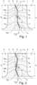
- Fig. 1 and Fig. 2 each show a cross-section through a profile block 1 ( Fig.1 ), 2 ( Fig.2 ), which belongs to a tread of a pneumatic vehicle tire.
- the tread has a plurality of profile blocks 1 and/or 2.
- the circumferential direction of the tire is indicated by a double arrow U.
- the profile block 1, 2 is circumferentially separated by Fig. 1 and Fig. 2 merely indicated transverse grooves 3 and laterally by further grooves not shown, for example circumferential grooves.
- the transverse grooves 3 are designed in the radial direction to the respectively intended tread depth T P , which in the mentioned, preferred tire type is usually 6.5 mm to 12.0 mm, in particular 7.0 mm to 9.5 mm.
- the profile block 1, 2 has an outer block surface 4 on the tread periphery and is - in relation to its circumferential extent - provided in its central region with an incision 5 (profile block 1), 6 (profile block 2) extending from the outer block surface 4 into the radial interior of the profile block 1, 2 with two incision edges 9 located on the outer block surface 4.
- the Fig. 1 and Fig. 2 The cross-section shown runs, viewed in plan view (not shown), perpendicular to the incision edges 9.
- the incision 5, 6 can pass through the profile block 1 or 2 or end on one or both sides within the profile block 1, 2 and runs, in each case viewed in plan view, and to the axial direction at an angle of 0° to 50°, in particular of up to 35°, and is straight, curved, undulating or undulating and additionally curved overall.
- the angle refers to the incision center line and in the case of incisions that are curved or curved overall in plan view, it refers to a straight line connecting the ends of the incision center line.
- the incision center line coincides with the shaft center line that corresponds to the direction of propagation of the wave in plan view.
- the incision 5, 6 is delimited by two incision walls 7 extending from the incision edges 9 and facing one another and by an incision base 8, has a constant width b E of 0.4 mm to 1.2 mm, in particular of up to 0.8 mm, determined between and perpendicular to the incision walls 7, a maximum depth t E (depth at the deepest point) measured in the radial direction and an incision center area m F at a corresponding distance from the incision walls 7, 7'.
- the maximum depth t E is at least the profile depth T P reduced by 2.0 mm and at most 100% of the profile depth Tp, wherein the maximum depth t E preferably corresponds to at most the profile depth T P reduced by 0.5 mm, particularly preferably at most 1.5 mm.
- the incision 5, 6 is designed to the maximum depth t E over its entire extent.
- the incision 5, 6 viewed in a cross-section running perpendicular to the incision edges 9 in plan view, has a straight, radially outer incision section 10a, a straight, middle incision section 10b adjoining this and a straight, radially inner incision section 10c.
- the incision 5, 6 is made up of the incision sections 10a, 10b, 10c.
- the incision 5, 6 can have a further incision section running in the radial direction or at an angle of 0° to 2° thereto, starting from the block outer surface 4 and adjoining the radially outer incision section 10a, which - based on the incision middle surface m F - has a length determined in the radial direction of up to 1.0 mm, in particular of up to 0.5 mm.
- the radially outer incision section 10a extends to the radial direction at an angle ⁇ of 15° to 30°, in particular of 18° to 27°, preferably of 20° to 25° and has - based on the incision center area m F - a radial Direction determined length c a of 2.0 mm to 3.0 mm, in particular of up to 2.5 mm.
- the radially inner incision section 10c runs to the radial direction at an angle ⁇ of 15° to 30°, in particular of 18° to 27°, preferably of 20° to 25° and - based on the incision center area m F - has a length c c determined in the radial direction of 2.0 mm to 3.0 mm, in particular of up to 2.5 mm.
- the length c a deviates from the length c c by at most 0.3 mm, wherein it is particularly preferred if the lengths c a , c c match.
- the angle ⁇ deviates from the angle ⁇ by at most 3°.
- the angle ⁇ matches the angle ⁇ .
- the incision center area m F has a radially outer kink point K a at the mutual connection of the incision sections 10a, 10b and a radially inner kink point K b at the mutual connection of the incision sections 10b, 10c, whereby the kink points K a , K b appear as kink points in the cross section shown.
- Fig. 1 and Fig. 2 A reference line L 1 running in the radial direction through the radially outer end of the incision center surface m F and a reference line L 2 running in the radial direction through the radially outer kink point K a are drawn in each case.
- the design of the incision 5, 6 is such that the kink point K b is located on the reference line L 1 , on the reference line L 2 (incision 5) or between the reference line L 1 and the reference line L 2 (incision 6).
- the design of the incision 5, 6 is further such that the middle incision section 10b - based on the incision middle area m F - runs at an angle ⁇ of 0° to 30°, in particular of up to 20°, preferably of up to 18°, particularly preferably of up to 15°, very particularly preferably of up to 10°, to the radial direction.
- the angle ⁇ is 0°.
- the incisions can also be formed in profile ribs which run in the circumferential direction.
- the profile rib or the profile blocks can be provided with several of the incisions.
- the incisions can run in a shoulder-side profile rib or in shoulder-side profile blocks.
- the incisions each have the three incision sections described in at least one part of the associated incision, with this part preferably extending at least over the majority of the incision in plan view.
Landscapes
- Engineering & Computer Science (AREA)
- Mechanical Engineering (AREA)
- Tires In General (AREA)
Abstract
Description
- Die Erfindung betrifft einen Fahrzeugluftreifen mit einem Laufstreifen mit Profilblöcken oder zumindest einer Profilrippe jeweils mit in Draufsicht unter einem Winkel von 0° bis zu 50° zur axialen Richtung verlaufenden, einen Einschnittgrund und eine Einschnittmittelfläche aufweisenden Einschnitten mit einer Breite von 0,4 mm bis 1,2 mm und einer maximalen Tiefe, welche zumindest der um 2,0 mm verringerten Profiltiefe entspricht, wobei jeder Einschnitt zumindest in einem Teilbereich, im Querschnitt betrachtet, einen zur radialen Richtung geneigten, radial äußeren Einschnittabschnitt, einen bis zum Einschnittgrund reichenden, bezüglich der radialen Richtung gleichsinnig zum radial äußeren Einschnittabschnitt geneigten, radial inneren Einschnittabschnitt und einen zwischen diesen beiden Einschnittabschnitten verlaufenden mittleren Einschnittabschnitt aufweist, wobei die Einschnittmittelfläche am Anschluss des radial äußeren Einschnittabschnittes an den mittleren Einschnittabschnitt eine radial äußere Knickstelle und am Anschluss des mittleren Einschnittabschnittes an den radial inneren Einschnittabschnitt eine radial innere Knickstelle aufweist.
- Ein derartiger Fahrzeugluftreifen ist beispielsweise aus der
DE 10 2007 059 291 A1 bekannt. Der Laufstreifen des Reifens weist gemäß einem Ausführungsbeispiel Profilblöcke auf, welche mit in Draufsicht wellenförmig verlaufenden, insbesondere auf Profiltiefe reichende, eine Breite von 0,4 mm bis 0,6 mm aufweisenden Einschnitten versehen sind, welche, im Querschnitt betrachtet, einen radial äußeren Einschnittabschnitt, einen mittleren Einschnittabschnitt und einen radial inneren Einschnittabschnitt aufweisen. Der radial äußere Einschnittabschnitt verläuft unter Beibehaltung der Wellenform zur radialen Richtung unter einem spitzen Winkel. Der mittlere Einschnittabschnitt schließt über einen Knickbereich an den radial äußeren Einschnittabschnitt an, wobei im mittleren Einschnittabschnitt die Amplitude der Wellenform in Richtung zum radial inneren Ende des mittleren Einschnittabschnittes kontinuierlich auf null abnimmt. Der radial äußere Einschnittabschnitt und der mittlere Einschnittabschnitt verlaufen zur radialen Richtung jeweils unter einem Winkel von 20° bis 50°, insbesondere von etwa 35°. Der radial innere Einschnittabschnitt verläuft in radialer Richtung und ist unstrukturiert ausgeführt. Der Reifen soll ausgewogene Eigenschaften beim Fahren auf trockener, mit Schnee bedeckter und nasser Fahrbahn aufweisen. - Ein weiterer Fahrzeugluftreifen der eingangs genannten Art ist aus der
WO 94/21478 A1 - Die bei Reifen der eingangs genannten Art in den Profilpositiven des Laufstreifens ausgebildeten Einschnitte sind vor allem für die Schneeperformance günstig. Im Hinblick auf die sich über den Laufstreifenabrieb ändernde Steifigkeit der Profilpositive sind die Einschnitte verbesserungsfähig, insbesondere um einen ungleichmäßigen Abrieb durch eine auf ungleichmäßige Weise abnehmende Steifigkeit der Profilpositive zu vermeiden.
- Der Erfindung liegt daher die Aufgabe zugrunde, bei einem Fahrzeugluftreifen der eingangs genannten Art eine gute Schneeperformance und eine gleichmäßige bzw. im Wesentlichen gleichmäßige Steifigkeit der Profilpositive über den Laufstreifenabrieb sicherzustellen.
- Gelöst wird die gestellte Aufgabe erfindungsgemäß dadurch, dass der radial äußere Einschnittabschnitt und der radial innere Einschnittabschnitt jeweils eine auf die Einschnittmittelfläche bezogene, in radialer Richtung ermittelte Länge von 2,0 mm bis 3,0 mm aufweisen, wobei der radial äußere Einschnittabschnitt zur radialen Richtung unter einem Winkel von 15° bis 30° und der radial innere Einschnittabschnitt zur radialen Richtung unter einem Winkel von 15° bis 30° verläuft, wobei die radial innere Knickstelle der Einschnittmittelfläche
- a) auf einer in radialer Richtung verlaufenden ersten Bezugslinie, welche am radial äußeren Ende des radial äußeren Einschnittabschnittes durch die Einschnittmittelfläche verläuft,
- b) auf einer in radialer Richtung verlaufenden zweiten Bezugslinie, welche durch die radial äußere Knickstelle der Einschnittmittelfläche verläuft, oder
- c) zwischen der ersten Bezugslinie und der zweiten Bezugslinie liegt.
- Der radial äußere Einschnittabschnitt ermöglicht bei neuem bzw. wenig abgefahrenem Reifen durch seinen speziellen Winkel relativ zur radialen Richtung ein für die Schneegriffeigenschaften sehr günstiges Griffverhalten in Bereich der Einschnittkanten. Der radial innere Einschnittabschnitt sorgt in analoger Weise bei deutlich abgefahrenem Laufstreifen für einen erneuten, die Schneegriffeigenschaften betreffenden "Performanceboost". Es ist somit eine gute Schneeperformance über den gesamten Laufstreifenabrieb sichergestellt. Die spezielle Lage der radial inneren Knickstelle der Einschnittmittelfläche sorgt für eine gleichmäßige Steifigkeit der Profilelemente über den Laufstreifenabrieb.
- Gemäß einer bevorzugten Ausführung verläuft der mittlere Einschnittabschnitt zur radialen Richtung unter einem Winkel von 0° bis 30°, insbesondere von bis zu 20°, bevorzugt von bis zu 18°, besonders bevorzugt von bis zu 15°, ganz besonders bevorzugt von bis zu 10°. Eine derartige Auslegung des mittleren Einschnittabschnittes sorgt für eine besonders gleichmäßige Steifigkeit der Profilpositive über den Laufstreifenabrieb.
- In diesen Zusammenhang ist es von besonderem Vorteil, wenn der Winkel, unter welchem der mittlere Einschnittabschnitt zur radialen Richtung verläuft, 0° beträgt.
- Gemäß einer weiteren bevorzugten Ausführung ist der Einschnitt im Teilbereich, in welchem der Einschnitt den radial äußeren Einschnittabschnitt, den mittleren Einschnittabschnitt und den radial inneren Einschnittabschnitt aufweist, in radialer Richtung auf die maximale Tiefe ausgeführt, wodurch die Aufgabe auf besonders vorteilhafte Weise gelöst wird.
- Bevorzugter Weise beträgt die maximale Tiefe des Einschnittes höchstens 100% der Profiltiefe.
- Insbesondere beträgt die maximale Tiefe des Einschnittes höchstens der um 0,5 mm, bevorzugt höchstens der um 1,5 mm, verringerten Profiltiefe.
- Gemäß einer weiteren bevorzugten Ausführung setzt sich der Einschnitt zumindest im Teilbereich aus dem radial äußeren Einschnittabschnitt, dem radial inneren Einschnittabschnitt und dem mittleren Einschnittabschnitt zusammen.
- Gemäß einer zur letztgenannten Ausführung alternativen bevorzugten Ausführung setzt sich der Einschnitt zumindest im Teilbereich aus dem radial äußeren Einschnittabschnitt, dem radial inneren Einschnittabschnitt, dem mittleren Einschnittabschnitt und einem zur radialer Richtung unter einem Winkel von 0° bis 2° verlaufenden, von der Laufstreifenperipherie ausgehenden, weiteren Einschnittabschnitt mit einer in radialer Richtung eine Länge von bis zu 1,0 mm, insbesondere von bis zu 0,5 mm, zusammen. Ein solcher weiterer Einschnittabschnitt lässt die erläuterten, vorteilhaften Auswirkungen des radial äußeren Einschnittabschnittes auf die Schneegriffeigenschaften unbeeinflusst. Der weitere Einschnittabschnitt ist vor allem aus fertigungstechnischen Gründen bei der Vulkanisationsformherstellung vorteilhaft.
- Bevorzugter Weise beträgt der Winkel, unter welchem der radial äußere Einschnittabschnitt zur radialen Richtung verläuft, 18° bis 27°, insbesondere 20° bis 25°. Ein derartiger Winkel ist bei neuem bzw. wenig abgefahrenem Reifen für die Schneegriffeigenschaften von Vorteil.
- Insbesondere ist es für den erwähnten Performanceboost von Vorteil, wenn der Winkel, unter welchem der radial innere Einschnittabschnitt zur radialen Richtung verläuft, 18° bis 27°, insbesondere 20° bis 25°, beträgt.
- Eine weitere bevorzugte Ausführung ist dadurch gekennzeichnet, dass der Winkel, unter welchem der radial äußere Einschnittabschnitt zur radialen Richtung verläuft, vom Winkel, unter welchem der radial innere Einschnittabschnitt zur radialen Richtung verläuft, um höchstens 3° abweicht oder dass diese Winkel übereinstimmen. Diese Maßnahme trägt zusätzlich zu einer gleichmäßigen Steifigkeit der Profilpositive über den Laufstreifenabrieb bei.
- Eine weitere bevorzugte Ausführung, welche zur gleichmäßigen Steifigkeit der Profilpositive über den Laufstreifenabrieb beiträgt, ist dadurch gekennzeichnet, dass die Länge des radial äußeren Einschnittabschnittes von der Länge des radial inneren Einschnittabschnittes um höchstens 0,3 mm abweicht oder dass diese Längen übereinstimmen.
- Bevorzugter Weise beträgt die Länge des radial äußeren Einschnittabschnittes und die Länge des radial inneren Einschnittabschnittes bis zu 2,5 mm.
- Weitere Merkmale, Vorteile und Einzelheiten der Erfindung werden nun anhand der Zeichnung, die schematisch Ausführungsbeispiele der Erfindung zeigt, näher beschrieben. Dabei zeigen
-
Fig. 1 einen Schnitt durch einen Profilblock eines Laufstreifens eines Fahrzeugluftreifens mit einer ersten Ausführungsvariante der Erfindung und -
Fig. 2 einen Schnitt durch einen Profilblock eines Laufstreifens eines Fahrzeugluftreifens mit einer zweiten Ausführungsvariante der Erfindung. - Gemäß der Erfindung ausgeführte Fahrzeugluftreifen sind Reifen für Kraftfahrzeuge, insbesondere für mehrspurige Kraftfahrzeuge, sowie vorzugsweise Reifen in Radialbauart für Personenkraftwagen, Vans oder Light-Trucks (Leichte LKWs mit zGM ≤ 7,5 1), wobei die Reifen insbesondere für den Ganzjahreseinsatz oder zum Fahren unter winterlichen Fahrbedingungen vorgesehen sind.
-
Fig. 1 und Fig. 2 zeigen je einen Querschnitt durch einen Profilblock 1 (Fig. 1 ), 2 (Fig. 2 ), welcher zu einem Laufstreifen eines Fahrzeugluftreifens gehört. Der Laufstreifen weist eine Vielzahl von Profilblöcken 1 und/oder 2 auf. Die Umfangsrichtung des Reifens ist jeweils durch einen Doppelpfeil U gekennzeichnet. Der Profilblock 1, 2 ist in Umfangsrichtung durch inFig. 1 und Fig. 2 lediglich angedeutete Querrillen 3 sowie seitlich durch weitere, nicht gezeigte Rillen, beispielsweise Umfangsrillen, begrenzt. - Beim den gezeigten Ausführungsbeispielen sind die Querrillen 3 in radialer Richtung auf die jeweils vorgesehene Profiltiefe TP ausgeführt, welche beim erwähnten, bevorzugten Reifentyp üblicherweise 6,5 mm bis 12,0 mm, insbesondere 7,0 mm bis 9,5 mm, beträgt.
- Der Profilblock 1, 2 weist an der Laufstreifenperipherie eine Blockaußenfläche 4 auf und ist - bezogen auf seine Umfangserstreckung - in seinem mittleren Bereich mit einem von der Blockaußenfläche 4 ausgehenden, ins radial Innere des Profilblockes 1, 2 hineinragenden Einschnitt 5 (Profilblock 1), 6 (Profilblock 2) mit zwei an der Blockaußenfläche 4 liegenden Einschnittkanten 9 versehen. Der in
Fig. 1 und Fig. 2 gezeigte Querschnitt verläuft, betrachtet in Draufsicht (nicht gezeigt), jeweils senkrecht zu den Einschnittkanten 9. - Der Einschnitt 5, 6 kann den Profilblock 1 bzw. 2 durchqueren oder ein- bzw. beidseitig innerhalb des Profilblockes 1, 2 enden und verläuft, jeweils in Draufsicht betrachtet, sowie zur axialen Richtung unter einem Winkel von 0° bis 50°, insbesondere von bis zu 35° sowie gerade, bogenförmig, wellenförmig oder wellenförmig und zusätzlich insgesamt gebogen. Der Winkel bezieht sich bei in Draufsicht insgesamt gerade verlaufenden Einschnitten auf die Einschnittmittellinie und bei in Draufsicht bogenförmig bzw. insgesamt gebogen verlaufenden Einschnitten auf eine die Enden der Einschnittmittellinie verbindende gerade Linie. Bei wellenförmig verlaufenden Einschnitten fällt die Einschnittmittellinie mit der in Draufsicht der Ausbreitungsrichtung der Welle entsprechenden Wellenmittellinie zusammen.
- Der Einschnitt 5, 6 ist durch zwei von den Einschnittkanten 9 ausgehenden, einander gegenüberliegenden Einschnittwänden 7 und einem Einschnittgrund 8 begrenzt, weist eine zwischen sowie senkrecht zu den Einschnittwänden 7 ermittelte, konstante Breite bE von 0,4 mm bis 1,2 mm, insbesondere von bis zu 0,8 mm, eine in radialer Richtung gemessene maximale Tiefe tE (Tiefe an der tiefsten Stelle) und eine zu den Einschnittwänden 7, 7' übereinstimmend beabstandete Einschnittmittelfläche mF auf. Die maximale Tiefe tE beträgt zumindest der um 2,0 mm verringerten Profiltiefe TP und höchstens 100% der Profiltiefe Tp, wobei die maximale Tiefe tE vorzugsweise höchstens der um 0,5 mm, besonders bevorzugt höchstens der um 1,5 mm, verringerten Profiltiefe TP entspricht. Beim gezeigten Ausführungsbeispiel ist der Einschnitt 5, 6 über seine gesamte Erstreckung auf die maximale Tiefe tE ausgeführt.
- Der Einschnitt 5, 6 weist, im in Draufsicht senkrecht zu den Einschnittkanten 9 verlaufenden Querschnitt betrachtet, einen gerade verlaufenden, radial äußeren Einschnittabschnitt 10a, einen an diesen anschließenden, gerade verlaufenden, mittleren Einschnittabschnitt 10b und einen gerade verlaufenden, radial inneren Einschnittabschnitt 10c auf. Beim gezeigten Ausführungsbeispiel setzt sich der Einschnitt 5, 6 aus den Einschnittabschnitten 10a, 10b, 10c zusammen. Alternativ kann der Einschnitt 5, 6 zusätzlich zu den Einschnittabschnitten 10a, 10b, 10c einen in radialer Richtung oder zu dieser unter einem Winkel von 0° bis zu 2° verlaufenden, von der Blockaußenfläche 4 ausgehenden, an den radial äußeren Einschnittabschnitt 10a anschließenden weiteren Einschnittabschnitt aufweisen, welcher - bezogen auf die Einschnittmittelfläche mF - eine in radialer Richtung ermittelte Länge von bis zu 1,0 mm, insbesondere von bis zu 0,5 mm, aufweist.
- Die nachfolgenden, weiteren Erläuterungen beziehen sich auf den in Draufsicht senkrecht zu den Einschnittkanten 9 verlaufenden Querschnitt durch den Einschnitt 5, 6.
- Der radial äußere Einschnittabschnitt 10a verläuft zur radialen Richtung unter einem Winkel α von 15° bis 30°, insbesondere von 18° bis 27°, bevorzugt von 20° bis 25° und weist - bezogen auf die Einschnittmittelfläche mF - eine in radialer Richtung ermittelte Länge ca von 2,0 mm bis 3,0 mm, insbesondere von bis zu 2,5 mm, auf. Der radial innere Einschnittabschnitt 10c verläuft zur radialen Richtung unter einem Winkel γ von 15° bis 30°, insbesondere von 18° bis 27°, bevorzugt von 20° bis 25° und weist - bezogen auf die Einschnittmittelfläche mF - eine in radialer Richtung ermittelte Länge cc von 2,0 mm bis 3,0 mm, insbesondere von bis zu 2,5 mm, auf. Bevorzugter Weise weicht die Länge ca von der Länge cc um höchstens 0,3 mm ab, wobei es besonders bevorzugt ist, wenn die Längen ca, cc übereinstimmen. Bevorzugter Weise weicht der Winkel α vom Winkel γ um höchstens 3° ab. Besonders bevorzugter Weise stimmt der Winkel α mit dem Winkel γ überein.
- Die Einschnittmittelfläche mF weist am gegenseitigen Anschluss der Einschnittabschnitte 10a, 10b eine radial äußere Knickstelle Ka und am gegenseitigen Anschluss der Einschnittabschnitte 10b, 10c eine radial innere Knickstelle Kb auf, wobei die Knickstellen Ka, Kb im gezeigten Querschnitt als Knickpunkte erscheinen. In
Fig. 1 und Fig. 2 ist jeweils eine in radialer Richtung durch das radial äußere Ende der Einschnittmittelfläche mF verlaufende Bezugslinie L1 und eine in radialer Richtung durch die radial äußere Knickstelle Ka verlaufende Bezugslinie L2 eingezeichnet. - Die Ausgestaltung des Einschnittes 5, 6 ist derart, dass sich die Knickstelle Kb auf der Bezugslinie L1, auf der Bezugslinie L2 (Einschnitt 5) oder zwischen der Bezugslinie L1 und Bezugslinie L2 (Einschnitt 6) befindet.
- Bevorzugter Weise ist die Ausgestaltung des Einschnittes 5, 6 ferner derart, dass der mittlere Einschnittabschnitt 10b - bezogen auf die Einschnittmittelfläche mF - zur radialen Richtung unter einem Winkel β von 0° bis 30°, insbesondere von bis zu 20°, bevorzugt von bis zu 18°, besonders bevorzugt von bis zu 15°, ganz besonders bevorzugt von bis zu 10° verläuft. Beim Ausführungsbeispiel in
Fig. 1 beträgt der Winkel β 0°. - Die Erfindung ist auf die beschriebenen Ausführungsbeispiele nicht beschränkt.
- Insbesondere können die Einschnitte auch in Profilrippen, welche in Umfangsrichtung umlaufen, ausgebildet sein. Die Profilrippe bzw. die Profilblöcke können mit mehreren der Einschnitte versehen sein. Ferner können die Einschnitte in einer schulterseitigen Profilrippe bzw. in schulterseitigen Profilblöcken verlaufen. Die Einschnitte weisen die beschriebenen drei Einschnittabschnitte jeweils zumindest in einem Teil des zugehörigen Einschnittes auf, wobei dieser Teil in Draufsicht vorzugsweise zumindest über den Großteil des Einschnittes reicht.
-
- 1
- Profilblock
- 2
- Profilblock
- 3
- Querrille
- 4
- Blockaußenfläche
- 5
- Einschnitt
- 6
- Einschnitt
- 7
- Einschnittwand
- 8
- Einschnittgrund
- 9
- Einschnittkante
- 10a
- radial äußerer Einschnittabschnitt
- 10b
- mittlerer Einschnittabschnitt
- 10c
- radial innerer Einschnittabschnitt
- bE
- Breite
- ca, cc
- Länge
- Ka
- radial äußere Knickstelle
- Kb
- radial innere Knickstelle
- L1, L2
- Bezugslinie
- mF
- Einschnittmittelfläche
- tE
- maximale Tiefe
- TP
- Profiltiefe
- U
- Doppelpfeil (Umfangsrichtung)
- α, β, γ
- Winkel
Claims (13)
- Fahrzeugluftreifen mit einem Laufstreifen mit Profilblöcken (1, 2) oder zumindest einer Profilrippe jeweils mit in Draufsicht unter einem Winkel von 0° bis zu 50° zur axialen Richtung verlaufenden, einen Einschnittgrund (8) und eine Einschnittmittelfläche (mF) aufweisenden Einschnitten (5, 6) mit einer Breite (bE) von 0,4 mm bis 1,2 mm und einer maximalen Tiefe (tE), welche zumindest der um 2,0 mm verringerten Profiltiefe (TP) entspricht, wobei jeder Einschnitt (5, 6) zumindest in einem Teilbereich, im Querschnitt betrachtet, einen zur radialen Richtung geneigten, radial äußeren Einschnittabschnitt (10a), einen bis zum Einschnittgrund (8) reichenden, bezüglich der radialen Richtung gleichsinnig zum radial äußeren Einschnittabschnitt (10a) geneigten, radial inneren Einschnittabschnitt (10c) und einen zwischen diesen beiden Einschnittabschnitten (10a, 10c) verlaufenden mittleren Einschnittabschnitt (10b) aufweist, wobei die Einschnittmittelfläche (mF) am Anschluss des radial äußeren Einschnittabschnittes (10a) an den mittleren Einschnittabschnitt (10b) eine radial äußere Knickstelle (Ka) und am Anschluss des mittleren Einschnittabschnittes (10b) an den radial inneren Einschnittabschnitt (10c) eine radial innere Knickstelle (Kb) aufweist,
dadurch gekennzeichnet,
dass der radial äußere Einschnittabschnitt (10a) und der radial innere Einschnittabschnitt (10c) jeweils eine auf die Einschnittmittelfläche (mF) bezogene, in radialer Richtung ermittelte Länge (ca, cc) von 2,0 mm bis 3,0 mm aufweisen, wobei der radial äußere Einschnittabschnitt (10a) zur radialen Richtung unter einem Winkel (α) von 15° bis 30° und der radial innere Einschnittabschnitt (10c) zur radialen Richtung unter einem Winkel (γ) von 15° bis 30° verläuft, wobei die radial innere Knickstelle (Kb) der Einschnittmittelfläche (mF)a) auf einer in radialer Richtung verlaufenden ersten Bezugslinie (L1), welche am radial äußeren Ende des radial äußeren Einschnittabschnittes (10a) durch die Einschnittmittelfläche (mF) verläuft,b) auf einer in radialer Richtung verlaufenden zweiten Bezugslinie (L2), welche durch die radial äußere Knickstelle (Ka) der Einschnittmittelfläche (mF) verläuft,
oderc) zwischen der ersten Bezugslinie (L1) und der zweiten Bezugslinie (L2) liegt. - Fahrzeugluftreifen nach Anspruch 1, dadurch gekennzeichnet, dass der mittlere Einschnittabschnitt (10b) zur radialen Richtung unter einem Winkel (β) von 0° bis 30°, insbesondere von bis zu 20°, bevorzugt von bis zu 18°, besonders bevorzugt von bis zu 15°, ganz besonders bevorzugt von bis zu 10°, verläuft.
- Fahrzeugluftreifen nach Anspruch 2, dadurch gekennzeichnet, dass der Winkel (β), unter welchem der mittlere Einschnittabschnitt (10b) zur radialen Richtung verläuft, 0° beträgt.
- Fahrzeugluftreifen nach einem der Ansprüche 1 bis 3, dadurch gekennzeichnet, dass der Einschnitt (10) im Teilbereich, in welchem der Einschnitt (10) den radial äußeren Einschnittabschnitt (10a), den mittleren Einschnittabschnitt (10b) und den radial inneren Einschnittabschnitt (10c) aufweist, in radialer Richtung auf die maximale Tiefe (tE) ausgeführt ist.
- Fahrzeugluftreifen nach einem der Ansprüche 1 bis 4, dadurch gekennzeichnet, dass die maximale Tiefe (tE) des Einschnittes (5, 6) höchstens 100% der Profiltiefe (TP) beträgt.
- Fahrzeugluftreifen nach einem der Ansprüche 1 bis 4, dadurch gekennzeichnet, dass die maximale Tiefe (tE) des Einschnittes (5, 6) höchstens der um 0,5 mm, bevorzugt höchstens der um 1,5 mm, verringerten Profiltiefe (TP) beträgt.
- Fahrzeugluftreifen nach einem der Ansprüche 1 bis 6, dadurch gekennzeichnet, dass sich der Einschnitt (5, 6) zumindest im Teilbereich aus dem radial äußeren Einschnittabschnitt (10a), dem radial inneren Einschnittabschnitt (10c) und dem mittleren Einschnittabschnitt (10b) zusammensetzt.
- Fahrzeugluftreifen nach einem der Ansprüche 1 bis 6, dadurch gekennzeichnet, dass sich der Einschnitt (5, 6) zumindest im Teilbereich aus dem radial äußeren Einschnittabschnitt (10a), dem radial inneren Einschnittabschnitt (10c), dem mittleren Einschnittabschnitt (10b) und einem zur radialer Richtung unter einem Winkel von 0° bis 2° verlaufenden, von der Laufstreifenperipherie ausgehenden, weiteren Einschnittabschnitt mit einer in radialer Richtung ermittelten Länge von bis zu 1,0 mm, insbesondere von bis zu 0,5 mm, zusammensetzt.
- Fahrzeugluftreifen nach einem der Ansprüche 1 bis 8, dadurch gekennzeichnet, dass der Winkel (α), unter welchem der radial äußere Einschnittabschnitt (10a) zur radialen Richtung verläuft, 18° bis 27°, insbesondere 20° bis 25°, beträgt.
- Fahrzeugluftreifen nach einem der Ansprüche 1 bis 9, dadurch gekennzeichnet, dass der Winkel (γ), unter welchem der radial innere Einschnittabschnitt (10c) zur radialen Richtung verläuft, 18° bis 27°, insbesondere 20° bis 25°, beträgt.
- Fahrzeugluftreifen nach einem der Ansprüche 1 bis 10, dadurch gekennzeichnet, dass der Winkel (α), unter welchem der radial äußere Einschnittabschnitt (10a) zur radialen Richtung verläuft, vom Winkel (γ), unter welchem der radial innere Einschnittabschnitt (10c) zur radialen Richtung verläuft, um höchstens 3° abweicht oder dass diese Winkel (α, γ) übereinstimmen.
- Fahrzeugluftreifen nach einem der Ansprüche 1 bis 11, dadurch gekennzeichnet, dass die Länge (ca) des radial äußeren Einschnittabschnittes (10a) von der Länge (cc) des radial inneren Einschnittabschnittes (10c) um höchstens 0,3 mm abweicht oder dass diese Längen (ca, cc) übereinstimmen.
- Fahrzeugluftreifen nach einem der Ansprüche 1 bis 12, dadurch gekennzeichnet, dass die Länge (ca) des radial äußeren Einschnittabschnittes (10a) und die Länge (cc) des radial inneren Einschnittabschnittes (10c) bis zu 2,5 mm beträgt.
Applications Claiming Priority (1)
| Application Number | Priority Date | Filing Date | Title |
|---|---|---|---|
| DE102022213492.3A DE102022213492A1 (de) | 2022-12-12 | 2022-12-12 | Fahrzeugluftreifen |
Publications (2)
| Publication Number | Publication Date |
|---|---|
| EP4385761A1 true EP4385761A1 (de) | 2024-06-19 |
| EP4385761B1 EP4385761B1 (de) | 2025-08-27 |
Family
ID=89164558
Family Applications (1)
| Application Number | Title | Priority Date | Filing Date |
|---|---|---|---|
| EP23215378.3A Active EP4385761B1 (de) | 2022-12-12 | 2023-12-08 | Fahrzeugluftreifen |
Country Status (2)
| Country | Link |
|---|---|
| EP (1) | EP4385761B1 (de) |
| DE (1) | DE102022213492A1 (de) |
Citations (11)
| Publication number | Priority date | Publication date | Assignee | Title |
|---|---|---|---|---|
| WO1994021478A1 (fr) | 1993-03-25 | 1994-09-29 | Compagnie Generale Des Etablissements Michelin - Michelin & Cie | Bande de roulement pour pneumatique radial ayant des elements en relief pourvus d'incisions |
| EP1277599A2 (de) * | 2001-07-18 | 2003-01-22 | Sumitomo Rubber Industries Ltd. | Luftreifen |
| US20050150581A1 (en) * | 2004-01-09 | 2005-07-14 | Sumitomo Rubber Industries, Ltd. | Pneumatic tire |
| US20090000713A1 (en) * | 2007-06-27 | 2009-01-01 | Bridgestone Firestone North American Tire, Llc | Tire including segmented sipes |
| JP2009012678A (ja) * | 2007-07-06 | 2009-01-22 | Yokohama Rubber Co Ltd:The | 空気入りタイヤ |
| DE102007059291A1 (de) | 2007-12-08 | 2009-06-10 | Continental Aktiengesellschaft | Fahrzeugluftreifen |
| EP2138330A1 (de) * | 2008-06-28 | 2009-12-30 | Continental Aktiengesellschaft | Fahrzeugluftreifen |
| US20130133799A1 (en) * | 2011-11-28 | 2013-05-30 | The Yorkohama Rubber Co., LTD. | Pneumatic Tire |
| US20150266346A1 (en) * | 2012-10-24 | 2015-09-24 | Bridgestone Corporation | Pneumatic tire |
| WO2015176958A1 (en) * | 2014-05-20 | 2015-11-26 | Apollo Tyres Global R&D B.V. | Tire profile and molding form |
| JP2017024476A (ja) * | 2015-07-17 | 2017-02-02 | 住友ゴム工業株式会社 | タイヤ |
-
2022
- 2022-12-12 DE DE102022213492.3A patent/DE102022213492A1/de active Pending
-
2023
- 2023-12-08 EP EP23215378.3A patent/EP4385761B1/de active Active
Patent Citations (11)
| Publication number | Priority date | Publication date | Assignee | Title |
|---|---|---|---|---|
| WO1994021478A1 (fr) | 1993-03-25 | 1994-09-29 | Compagnie Generale Des Etablissements Michelin - Michelin & Cie | Bande de roulement pour pneumatique radial ayant des elements en relief pourvus d'incisions |
| EP1277599A2 (de) * | 2001-07-18 | 2003-01-22 | Sumitomo Rubber Industries Ltd. | Luftreifen |
| US20050150581A1 (en) * | 2004-01-09 | 2005-07-14 | Sumitomo Rubber Industries, Ltd. | Pneumatic tire |
| US20090000713A1 (en) * | 2007-06-27 | 2009-01-01 | Bridgestone Firestone North American Tire, Llc | Tire including segmented sipes |
| JP2009012678A (ja) * | 2007-07-06 | 2009-01-22 | Yokohama Rubber Co Ltd:The | 空気入りタイヤ |
| DE102007059291A1 (de) | 2007-12-08 | 2009-06-10 | Continental Aktiengesellschaft | Fahrzeugluftreifen |
| EP2138330A1 (de) * | 2008-06-28 | 2009-12-30 | Continental Aktiengesellschaft | Fahrzeugluftreifen |
| US20130133799A1 (en) * | 2011-11-28 | 2013-05-30 | The Yorkohama Rubber Co., LTD. | Pneumatic Tire |
| US20150266346A1 (en) * | 2012-10-24 | 2015-09-24 | Bridgestone Corporation | Pneumatic tire |
| WO2015176958A1 (en) * | 2014-05-20 | 2015-11-26 | Apollo Tyres Global R&D B.V. | Tire profile and molding form |
| JP2017024476A (ja) * | 2015-07-17 | 2017-02-02 | 住友ゴム工業株式会社 | タイヤ |
Non-Patent Citations (1)
| Title |
|---|
| ANONYMOUS: "Reifenprofiltiefe | Continental Reifen", 6 March 2021 (2021-03-06), pages 1 - 6, XP093152502, Retrieved from the Internet <URL:https://www.continental-reifen.de/b2c/tire-knowledge/tread-depth/> * |
Also Published As
| Publication number | Publication date |
|---|---|
| DE102022213492A1 (de) | 2024-06-13 |
| EP4385761B1 (de) | 2025-08-27 |
Similar Documents
| Publication | Publication Date | Title |
|---|---|---|
| EP3888948B1 (de) | Fahrzeugluftreifen, insbesondere nutzfahrzeugreifen | |
| EP0669216A1 (de) | Fahrzeugluftreifen | |
| WO2009037056A1 (de) | Fahrzeugluftreifen | |
| WO2019001790A1 (de) | Fahrzeugluftreifen | |
| DE102019213044A1 (de) | Fahrzeugluftreifen | |
| WO2019115036A1 (de) | Nutzfahrzeugreifen | |
| DE102018208670A1 (de) | Fahrzeugluftreifen | |
| EP3277523B1 (de) | Fahrzeugluftreifen | |
| EP4577416A1 (de) | Fahrzeugluftreifen | |
| EP3130481B1 (de) | Fahrzeugluftreifen | |
| DE102016224803A1 (de) | Fahrzeugluftreifen | |
| EP4171972B1 (de) | Fahrzeugluftreifen | |
| EP2138329B1 (de) | Laufflächenprofil für einen Fahrzeugluftreifen | |
| EP2138328B1 (de) | Fahrzeugluftreifen | |
| EP4347276B1 (de) | Fahrzeugluftreifen | |
| EP3300925B1 (de) | Fahrzeugluftreifen | |
| EP4385761B1 (de) | Fahrzeugluftreifen | |
| EP4003760B1 (de) | Fahrzeugluftreifen | |
| WO2018103920A1 (de) | Fahrzeugluftreifen | |
| EP4173847A1 (de) | Fahrzeugluftreifen | |
| EP2000329A1 (de) | Fahrzeugluftreifen | |
| EP4434768B1 (de) | Fahrzeugluftreifen | |
| EP4628328A1 (de) | Fahrzeugreifen | |
| EP4389462A1 (de) | Fahrzeugluftreifen | |
| DE102024205989A1 (de) | Fahrzeugreifen |
Legal Events
| Date | Code | Title | Description |
|---|---|---|---|
| PUAI | Public reference made under article 153(3) epc to a published international application that has entered the european phase |
Free format text: ORIGINAL CODE: 0009012 |
|
| STAA | Information on the status of an ep patent application or granted ep patent |
Free format text: STATUS: THE APPLICATION HAS BEEN PUBLISHED |
|
| AK | Designated contracting states |
Kind code of ref document: A1 Designated state(s): AL AT BE BG CH CY CZ DE DK EE ES FI FR GB GR HR HU IE IS IT LI LT LU LV MC ME MK MT NL NO PL PT RO RS SE SI SK SM TR |
|
| STAA | Information on the status of an ep patent application or granted ep patent |
Free format text: STATUS: REQUEST FOR EXAMINATION WAS MADE |
|
| 17P | Request for examination filed |
Effective date: 20241219 |
|
| GRAP | Despatch of communication of intention to grant a patent |
Free format text: ORIGINAL CODE: EPIDOSNIGR1 |
|
| STAA | Information on the status of an ep patent application or granted ep patent |
Free format text: STATUS: GRANT OF PATENT IS INTENDED |
|
| INTG | Intention to grant announced |
Effective date: 20250422 |
|
| GRAS | Grant fee paid |
Free format text: ORIGINAL CODE: EPIDOSNIGR3 |
|
| GRAA | (expected) grant |
Free format text: ORIGINAL CODE: 0009210 |
|
| STAA | Information on the status of an ep patent application or granted ep patent |
Free format text: STATUS: THE PATENT HAS BEEN GRANTED |
|
| AK | Designated contracting states |
Kind code of ref document: B1 Designated state(s): AL AT BE BG CH CY CZ DE DK EE ES FI FR GB GR HR HU IE IS IT LI LT LU LV MC ME MK MT NL NO PL PT RO RS SE SI SK SM TR |
|
| REG | Reference to a national code |
Ref country code: CH Ref legal event code: EP |
|
| REG | Reference to a national code |
Ref country code: DE Ref legal event code: R096 Ref document number: 502023001679 Country of ref document: DE |
|
| REG | Reference to a national code |
Ref country code: IE Ref legal event code: FG4D Free format text: LANGUAGE OF EP DOCUMENT: GERMAN |
|
| REG | Reference to a national code |
Ref country code: NL Ref legal event code: FP |
|
| PG25 | Lapsed in a contracting state [announced via postgrant information from national office to epo] |
Ref country code: IS Free format text: LAPSE BECAUSE OF FAILURE TO SUBMIT A TRANSLATION OF THE DESCRIPTION OR TO PAY THE FEE WITHIN THE PRESCRIBED TIME-LIMIT Effective date: 20251227 |
|
| PG25 | Lapsed in a contracting state [announced via postgrant information from national office to epo] |
Ref country code: NO Free format text: LAPSE BECAUSE OF FAILURE TO SUBMIT A TRANSLATION OF THE DESCRIPTION OR TO PAY THE FEE WITHIN THE PRESCRIBED TIME-LIMIT Effective date: 20251127 |
|
| REG | Reference to a national code |
Ref country code: LT Ref legal event code: MG9D |
|
| PG25 | Lapsed in a contracting state [announced via postgrant information from national office to epo] |
Ref country code: PT Free format text: LAPSE BECAUSE OF FAILURE TO SUBMIT A TRANSLATION OF THE DESCRIPTION OR TO PAY THE FEE WITHIN THE PRESCRIBED TIME-LIMIT Effective date: 20251229 |
|
| PGFP | Annual fee paid to national office [announced via postgrant information from national office to epo] |
Ref country code: AT Payment date: 20260113 Year of fee payment: 3 |
|
| PG25 | Lapsed in a contracting state [announced via postgrant information from national office to epo] |
Ref country code: FI Free format text: LAPSE BECAUSE OF FAILURE TO SUBMIT A TRANSLATION OF THE DESCRIPTION OR TO PAY THE FEE WITHIN THE PRESCRIBED TIME-LIMIT Effective date: 20250827 |
|
| PG25 | Lapsed in a contracting state [announced via postgrant information from national office to epo] |
Ref country code: HR Free format text: LAPSE BECAUSE OF FAILURE TO SUBMIT A TRANSLATION OF THE DESCRIPTION OR TO PAY THE FEE WITHIN THE PRESCRIBED TIME-LIMIT Effective date: 20250827 |
|
| PGFP | Annual fee paid to national office [announced via postgrant information from national office to epo] |
Ref country code: FR Payment date: 20251229 Year of fee payment: 3 |
|
| PG25 | Lapsed in a contracting state [announced via postgrant information from national office to epo] |
Ref country code: GR Free format text: LAPSE BECAUSE OF FAILURE TO SUBMIT A TRANSLATION OF THE DESCRIPTION OR TO PAY THE FEE WITHIN THE PRESCRIBED TIME-LIMIT Effective date: 20251128 |
|
| PG25 | Lapsed in a contracting state [announced via postgrant information from national office to epo] |
Ref country code: SE Free format text: LAPSE BECAUSE OF FAILURE TO SUBMIT A TRANSLATION OF THE DESCRIPTION OR TO PAY THE FEE WITHIN THE PRESCRIBED TIME-LIMIT Effective date: 20250827 |
|
| PG25 | Lapsed in a contracting state [announced via postgrant information from national office to epo] |
Ref country code: LV Free format text: LAPSE BECAUSE OF FAILURE TO SUBMIT A TRANSLATION OF THE DESCRIPTION OR TO PAY THE FEE WITHIN THE PRESCRIBED TIME-LIMIT Effective date: 20250827 |
|
| PG25 | Lapsed in a contracting state [announced via postgrant information from national office to epo] |
Ref country code: PL Free format text: LAPSE BECAUSE OF FAILURE TO SUBMIT A TRANSLATION OF THE DESCRIPTION OR TO PAY THE FEE WITHIN THE PRESCRIBED TIME-LIMIT Effective date: 20250827 Ref country code: BG Free format text: LAPSE BECAUSE OF FAILURE TO SUBMIT A TRANSLATION OF THE DESCRIPTION OR TO PAY THE FEE WITHIN THE PRESCRIBED TIME-LIMIT Effective date: 20250827 |
|
| PG25 | Lapsed in a contracting state [announced via postgrant information from national office to epo] |
Ref country code: RS Free format text: LAPSE BECAUSE OF FAILURE TO SUBMIT A TRANSLATION OF THE DESCRIPTION OR TO PAY THE FEE WITHIN THE PRESCRIBED TIME-LIMIT Effective date: 20251127 |
|
| PG25 | Lapsed in a contracting state [announced via postgrant information from national office to epo] |
Ref country code: ES Free format text: LAPSE BECAUSE OF FAILURE TO SUBMIT A TRANSLATION OF THE DESCRIPTION OR TO PAY THE FEE WITHIN THE PRESCRIBED TIME-LIMIT Effective date: 20250827 |
|
| PG25 | Lapsed in a contracting state [announced via postgrant information from national office to epo] |
Ref country code: RO Free format text: LAPSE BECAUSE OF FAILURE TO SUBMIT A TRANSLATION OF THE DESCRIPTION OR TO PAY THE FEE WITHIN THE PRESCRIBED TIME-LIMIT Effective date: 20250827 |
|
| PG25 | Lapsed in a contracting state [announced via postgrant information from national office to epo] |
Ref country code: SM Free format text: LAPSE BECAUSE OF FAILURE TO SUBMIT A TRANSLATION OF THE DESCRIPTION OR TO PAY THE FEE WITHIN THE PRESCRIBED TIME-LIMIT Effective date: 20250827 |
|
| PG25 | Lapsed in a contracting state [announced via postgrant information from national office to epo] |
Ref country code: DK Free format text: LAPSE BECAUSE OF FAILURE TO SUBMIT A TRANSLATION OF THE DESCRIPTION OR TO PAY THE FEE WITHIN THE PRESCRIBED TIME-LIMIT Effective date: 20250827 |
|
| PGFP | Annual fee paid to national office [announced via postgrant information from national office to epo] |
Ref country code: DE Payment date: 20251231 Year of fee payment: 3 |
|
| PG25 | Lapsed in a contracting state [announced via postgrant information from national office to epo] |
Ref country code: IT Free format text: LAPSE BECAUSE OF FAILURE TO SUBMIT A TRANSLATION OF THE DESCRIPTION OR TO PAY THE FEE WITHIN THE PRESCRIBED TIME-LIMIT Effective date: 20250827 |
|
| PG25 | Lapsed in a contracting state [announced via postgrant information from national office to epo] |
Ref country code: CZ Free format text: LAPSE BECAUSE OF FAILURE TO SUBMIT A TRANSLATION OF THE DESCRIPTION OR TO PAY THE FEE WITHIN THE PRESCRIBED TIME-LIMIT Effective date: 20250827 |
|
| PG25 | Lapsed in a contracting state [announced via postgrant information from national office to epo] |
Ref country code: SK Free format text: LAPSE BECAUSE OF FAILURE TO SUBMIT A TRANSLATION OF THE DESCRIPTION OR TO PAY THE FEE WITHIN THE PRESCRIBED TIME-LIMIT Effective date: 20250827 Ref country code: EE Free format text: LAPSE BECAUSE OF FAILURE TO SUBMIT A TRANSLATION OF THE DESCRIPTION OR TO PAY THE FEE WITHIN THE PRESCRIBED TIME-LIMIT Effective date: 20250827 |