EP4385751A1 - Corrosion protection for aircraft wheel pneumatic ports - Google Patents
Corrosion protection for aircraft wheel pneumatic ports Download PDFInfo
- Publication number
- EP4385751A1 EP4385751A1 EP23214389.1A EP23214389A EP4385751A1 EP 4385751 A1 EP4385751 A1 EP 4385751A1 EP 23214389 A EP23214389 A EP 23214389A EP 4385751 A1 EP4385751 A1 EP 4385751A1
- Authority
- EP
- European Patent Office
- Prior art keywords
- various embodiments
- air channel
- valve
- mitigation device
- wheel
- Prior art date
- Legal status (The legal status is an assumption and is not a legal conclusion. Google has not performed a legal analysis and makes no representation as to the accuracy of the status listed.)
- Pending
Links
Images




Classifications
-
- B—PERFORMING OPERATIONS; TRANSPORTING
- B60—VEHICLES IN GENERAL
- B60B—VEHICLE WHEELS; CASTORS; AXLES FOR WHEELS OR CASTORS; INCREASING WHEEL ADHESION
- B60B21/00—Rims
- B60B21/02—Rims characterised by transverse section
-
- B—PERFORMING OPERATIONS; TRANSPORTING
- B60—VEHICLES IN GENERAL
- B60C—VEHICLE TYRES; TYRE INFLATION; TYRE CHANGING; CONNECTING VALVES TO INFLATABLE ELASTIC BODIES IN GENERAL; DEVICES OR ARRANGEMENTS RELATED TO TYRES
- B60C29/00—Arrangements of tyre-inflating valves to tyres or rims; Accessories for tyre-inflating valves, not otherwise provided for
- B60C29/06—Accessories for tyre-inflating valves, e.g. housings, guards, covers for valve caps, locks, not otherwise provided for
-
- B—PERFORMING OPERATIONS; TRANSPORTING
- B60—VEHICLES IN GENERAL
- B60B—VEHICLE WHEELS; CASTORS; AXLES FOR WHEELS OR CASTORS; INCREASING WHEEL ADHESION
- B60B19/00—Wheels not otherwise provided for or having characteristics specified in one of the subgroups of this group
- B60B19/08—Wheels not otherwise provided for or having characteristics specified in one of the subgroups of this group with lubricating passages, channels, or reservoirs
-
- B—PERFORMING OPERATIONS; TRANSPORTING
- B60—VEHICLES IN GENERAL
- B60B—VEHICLE WHEELS; CASTORS; AXLES FOR WHEELS OR CASTORS; INCREASING WHEEL ADHESION
- B60B21/00—Rims
- B60B21/02—Rims characterised by transverse section
- B60B21/026—Rims characterised by transverse section the shape of rim well
-
- B—PERFORMING OPERATIONS; TRANSPORTING
- B60—VEHICLES IN GENERAL
- B60B—VEHICLE WHEELS; CASTORS; AXLES FOR WHEELS OR CASTORS; INCREASING WHEEL ADHESION
- B60B25/00—Rims built-up of several main parts ; Locking means for the rim parts
- B60B25/002—Rims split in circumferential direction
-
- B—PERFORMING OPERATIONS; TRANSPORTING
- B60—VEHICLES IN GENERAL
- B60B—VEHICLE WHEELS; CASTORS; AXLES FOR WHEELS OR CASTORS; INCREASING WHEEL ADHESION
- B60B3/00—Disc wheels, i.e. wheels with load-supporting disc body
-
- B—PERFORMING OPERATIONS; TRANSPORTING
- B60—VEHICLES IN GENERAL
- B60C—VEHICLE TYRES; TYRE INFLATION; TYRE CHANGING; CONNECTING VALVES TO INFLATABLE ELASTIC BODIES IN GENERAL; DEVICES OR ARRANGEMENTS RELATED TO TYRES
- B60C2200/00—Tyres specially adapted for particular applications
- B60C2200/02—Tyres specially adapted for particular applications for aircrafts
-
- B—PERFORMING OPERATIONS; TRANSPORTING
- B60—VEHICLES IN GENERAL
- B60C—VEHICLE TYRES; TYRE INFLATION; TYRE CHANGING; CONNECTING VALVES TO INFLATABLE ELASTIC BODIES IN GENERAL; DEVICES OR ARRANGEMENTS RELATED TO TYRES
- B60C29/00—Arrangements of tyre-inflating valves to tyres or rims; Accessories for tyre-inflating valves, not otherwise provided for
- B60C29/02—Connection to rims
Definitions
- the present disclosure generally relates to pneumatic ports, and more particularly, to corrosion protection for aircraft wheel pneumatic ports.
- Each landing gear may include one or more wheel assemblies that may each receive an aircraft tire.
- Each wheel assembly may be split wheel assemblies, for example, and may have an inboard wheel portion and an outboard wheel portion. Such wheel portions of a split wheel are often held together using a plurality of tie bolts.
- Each wheel assembly may include at least one pneumatic port, such as an inflation valve for inflating the aircraft tire, an over-inflation pressure relief valves to prevent over-inflation of the aircraft tire, and a tire pressure monitoring system (TPMS) sensor that may communicate wirelessly with a controller of the aircraft.
- TPMS tire pressure monitoring system
- a wheel assembly is disclosed herein.
- the wheel assembly includes a structure defining a wheel portion configured to receive a portion of a tire; and a structure of the wheel portion defining an air channel from a face of the wheel portion to an area that receives the portion of the tire, an end of the air channel proximate to the face being configured to receive a valve, wherein the structure is further configured to receive a corrosion mitigation device within the air channel.
- the corrosion mitigation device is positioned in in an entry to the air channel, the entry being substantially near the face of the wheel portion, the air channel being configured to receive the valve, the corrosion mitigation device being located between the wheel assembly and the valve.
- the corrosion mitigation device is annular shaped.
- the corrosion mitigation device is positioned in an entry to the air channel substantially near the area that receives the portion of the tire.
- the corrosion mitigation device is tubular shaped.
- the corrosion mitigation device is configured to be positioned between threads of the wheel assembly configured to receive the valve and threads on an exterior of the valve. In various embodiments, the corrosion mitigation device is helically shaped to align with the threads of the wheel assembly and the threads on the exterior of the valve. In various embodiments, the corrosion mitigation device is an anodic device. In various embodiments, the corrosion mitigation device is a desiccant device.
- a landing gear of an aircraft including: a wheel assembly, the wheel assembly including: a structure defining a wheel portion configured to receive a portion of a tire; and a structure of the wheel portion defining an air channel from a face of the wheel portion to an area that receives the portion of the tire, an end of the air channel proximate to the face being configured to receive a valve, wherein the structure is further configured to receive a corrosion mitigation device within the air channel.
- the corrosion mitigation device is positioned in in an entry to the air channel, the entry being substantially near the face of the wheel portion, the air channel being configured to receive the valve, the corrosion mitigation device being located between the wheel assembly and the valve.
- the corrosion mitigation device is annular shaped.
- the corrosion mitigation device is positioned in an entry to the air channel substantially near the area that receives the portion of the tire.
- the corrosion mitigation device is tubular shaped.
- the corrosion mitigation device is configured to be positioned between threads of the wheel assembly configured to receive the valve and threads on an exterior of the valve. In various embodiments, the corrosion mitigation device is helically shaped to align with the threads of the wheel assembly and the threads on the exterior of the valve. In various embodiments, the corrosion mitigation device is an anodic device. In various embodiments, the corrosion mitigation device is a desiccant device.
- an aircraft including: a landing gear, where the landing gear includes a wheel assembly, the wheel assembly including: a structure defining a wheel portion configured to receive a portion of a tire; and a structure of the wheel portion defining an air channel from a face of the wheel portion to an area that receives the portion of the tire, an end of the air channel proximate to the face being configured to receive a valve, wherein the structure is further configured to receive a corrosion mitigation device within the air channel.
- the corrosion mitigation device is an anodic device or a desiccant device.
- references to "a,” “an” or “the” may include one or more than one and that reference to an item in the singular may also include the item in the plural. Further, all ranges may include upper and lower values and all ranges and ratio limits disclosed herein may be combined.
- Each landing gear may include one or more wheel assemblies that may each receive an aircraft tire.
- Each wheel assembly may include at least one pneumatic port, such as an inflation valve for inflating the aircraft tire, an over-inflation pressure relief valves to prevent over-inflation of the aircraft tire, and a tire pressure monitoring system (TPMS) sensor that may communicate wirelessly with a controller of the aircraft.
- TPMS tire pressure monitoring system
- a pneumatic port assembly that includes a corrosion mitigation device, such as an anodic device or a desiccant device, among others.
- the anodic device is a metal device that easily absorbs moisture that is present and corrodes thereby preventing corrosion of other parts of the pneumatic port assembly. That is, in various embodiments, the anodic device is metal substance that has a lower galvanic potential than the surrounding structure the anodic device protects. In that regard, the anodic device may be composed of less noble metals such as magnesium, zinc, beryllium, aluminum alloys, among others.
- the desiccant device is a hygroscopic substance disposed within a structure that is used to induce or sustain a state of dryness (desiccation) in its vicinity.
- the desiccant may be silica gel, activated charcoal, calcium sulfate, calcium chloride, molecular sieves, among others.
- the corrosion mitigation device is added to the pneumatic port assembly to mitigate corrosion within the pneumatic port due to moisture that may enter areas of the pneumatic port.
- the corrosion mitigation device may be in the form of a tubular shaped insert, an annular shaped insert, or a threaded insert, among others, that are easily replaceable during maintenance.
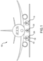
- an aircraft 100 in accordance with various embodiments can include multiple landing gear including a first landing gear 110, a second landing gear 120 and a third landing gear 130.
- Each landing gear may include one or more wheel assemblies 200 ( FIG. 3 ).
- the third landing gear 130 may include an inner/inboard wheel assembly and an outer/outboard wheel assembly.
- Each wheel assembly of the aircraft 100 may be designed to receive a tire.
- a tire 136 may be placed about an outer circumference of wheel assembly 200 and inflated.
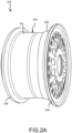
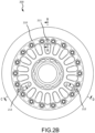
- wheel assembly 200 includes a split wheel including of a first wheel portion 201 and a second wheel portion 202, according to various embodiments. That is, wheel assembly 200 may include a split wheel having multiple wheel portions, such as an inboard wheel portion and an outboard wheel portion. Wheel portions 201, 202, for example, may be referred to as wheel halves (e.g., the first wheel portion 201 may be referred to as an inboard wheel half and the second wheel portion 202 may be referred to as an outboard wheel half).
- the wheel assembly 200 may be implemented with any landing gear of the aircraft 100 (e.g., any of the three landing gears mentioned above), and the wheel assembly 200 may be an inner/inboard wheel assembly or an outer/outboard assembly.
- wheel assembly 200 Although numerous details are included herein pertaining to the implementation of the wheel assembly 200 in an aircraft, one skilled in the art will realize that a similar wheel assembly may be used in other vehicles, such as cars or motorcycles, and thus the scope of the present disclosure is not necessarily limited to aircraft wheel assemblies.
- wheel assembly 200 also defines a tube-well 204.
- Tube-well 204 may be defined by respective flange sections of the first wheel portion 201 and the second wheel portion 202.
- Tube-well 204 may be configured to receive a tire and may form a seal with tire to allow pressurized air to inflate the tire.
- the first wheel portion 201 also includes a radially outward extending lip or rim 208 located at an inboard end of the first wheel portion 201
- the second wheel portion 202 may also include a similar radially outward extending lip or rim 209 located at an outboard end of the second wheel portion 202.
- a face 210 of the wheel assembly 200 may include one or more threaded portions to receive an inflation valve 211, over-inflation pressure relief valve 212, a tire pressure monitoring system (TPMS) valve 213, among others.
- TPMS tire pressure monitoring system
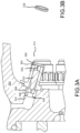
- the inflation valve 211 may include a post 302 that includes a first end 304 and a second end 306.
- the second end 306 may be removably fitted within a boundary defining a void 308 of the second wheel portion 202, such as by threaded attachment.
- the post 302 may include an air channel 312, located generally along the long axis of the post 302, that allows air to flow through the post 302.
- a valve core 316 may be removably mounted, such as by threading, within the first end 304 the post 302.
- the valve core 316 may include a one-way valve that permits air to flow into the air channel 312 in one direction, but not the other. In the disclosed example, the valve core 316 may allow air to flow into the air channel 312 through the first end 304 of the post 302, but not in the other direction.
- the inflation valve 211 may further include corrosion mitigation device 318 disposed within the air channel 314 at the second end 306 of post 302.
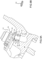
- the corrosion mitigation device 318 is an annular shaped device that permits air to flow from the air channel 312 into the air channel 314. Referring temporarily to FIG. 3B , an isometric view of the corrosion mitigation device 318 of FIG. 3A is illustrated, in accordance with various embodiments.
- the corrosion mitigation device 318 is an anodic device or a desiccant device, among others that absorbs moisture to mitigate corrosion within the pneumatic port.
- the inflation valve 211 may include a post 302 that includes a first end 304 and a second end 306.
- the second end 306 may be removably fitted within a boundary defining a void 308 of the second wheel portion 202, such as by threaded attachment.
- the post 302 may include an air channel 312, located generally along the long axis of the post 302, that allows air to flow through the post 302.
- a valve core 316 may be removably mounted, such as by threading, within the first end 304 the post 302.
- the valve core 316 may include a one-way valve that permits air to flow into the air channel 312 in one direction, but not the other. In the disclosed example, the valve core 316 may allow air to flow into the air channel 312 through the first end 304 of the post 302, but not in the other direction.
- air channel 314 of the second wheel portion 202 includes a first end 402 and a second end 404.
- a corrosion mitigation device 406 may be fitted into the second end 404 of the air channel 314 substantially near an area that receives at least a portion of a tire.
- the corrosion mitigation device 406 has a tubular shape that permits air coming from the air channel 312 through the air channel 314. Referring temporarily to FIG. 4B , an isometric view of the corrosion mitigation device 406 of FIG. 4A is illustrated, in accordance with various embodiments.
- the corrosion mitigation device 406 is an anodic device or a desiccant device, among others that absorbs moisture to mitigate corrosion within the pneumatic port.
- the inflation valve 211 may include a post 302 that includes a first end 304 and a second end 306.
- the second end 306 may be removably fitted within a boundary defining a void 308 of the second wheel portion 202, such as by threaded attachment.
- the post 302 may include an air channel 312, located generally along the long axis of the post 302, that allows air to flow through the post 302.
- a valve core 316 may be removably mounted, such as by threading, within the first end 304 the post 302.
- the valve core 316 may include a one-way valve that permits air to flow into the air channel 312 in one direction, but not the other. In the disclosed example, the valve core 316 may allow air to flow into the air channel 312 through the first end 304 of the post 302, but not in the other direction.
- the inflation valve 211 may further include corrosion mitigation device 502.
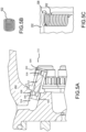
- corrosion mitigation device 502 may be a threaded insert with a helical shape, such as a helical coil as illustrated in FIG. 5B .
- the corrosion mitigation device 502 is inserted into threads of the boundary defining the void 308 of the second wheel portion 202, as illustrated in FIG. 5C , with the second end 306 of the post 302 threading into the corrosion mitigation device 502.
- the corrosion mitigation device 502 is an anodic device or a desiccant device, among others that absorbs moisture to mitigate corrosion within the pneumatic port.
- the TPMS valve 213 may include a pressure protector valve 602 fluidly coupled to a pressure duct 604.
- the pressure protector valve 602 may be removably fitted within a boundary defining a void 606 of the second wheel portion 202, such as by threaded attachment.
- the pressure protector valve 602 may include an air channel 608, located generally along the long axis of the pressure protector valve 602, that allows air to flow through the pressure protector valve 602.
- a valve core 612 may be removably mounted, such as by threading, within the pressure protector valve 602.
- the valve core 612 may include a one-way valve that permits air to flow into the air channel 608 in one direction, but not the other. In the disclosed example, the valve core 612 may allow air to flow into the air channel 608 through the pressure protector valve 602, but not in the other direction.
- the pressure protector valve 602 may further include corrosion mitigation device 614 configured to be disposed proximate the air channel 610 when the pressure protector valve 602 is fluidly coupled to the pressure duct 604.
- the corrosion mitigation device 614 is annular shaped device that permits air to flow from the air channel 608 into the air channel 610. Referring temporarily to FIG. 6B , an isometric view of the corrosion mitigation device 614 of FIG. 3A is illustrated, in accordance with various embodiments.
- the corrosion mitigation device 614 is an anodic device or a desiccant device, among others that absorbs moisture to mitigate corrosion within the pneumatic port.
- the TPMS valve 213 may include a pressure protector valve 602 fluidly coupled to a pressure duct 604.
- the pressure protector valve 602 may be removably fitted within a boundary defining a void 606 of the second wheel portion 202, such as by threaded attachment.
- the pressure protector valve 602 may include an air channel 608, located generally along the long axis of the pressure protector valve 602, that allows air to flow through the pressure protector valve 602.
- a valve core 612 may be removably mounted, such as by threading, within the pressure protector valve 602.
- the valve core 612 may include a one-way valve that permits air to flow into the air channel 608 in one direction, but not the other. In the disclosed example, the valve core 612 may allow air to flow into the air channel 608 through the pressure protector valve 602, but not in the other direction.
- air channel 610 of the second wheel portion 202 includes a first end 702 and a second end 704.
- a corrosion mitigation device 706 may be fitted into the second end 704 of the air channel 610 substantially near an area that receives at least a portion of a tire.
- the corrosion mitigation device 706 has a tubular shape that permits air to travel therethrough and through the air channel 610 and the air channel 608. Referring temporarily to FIG. 7B , an isometric view of the corrosion mitigation device 706 of FIG. 4A is illustrated, in accordance with various embodiments.
- the corrosion mitigation device 706 is an anodic device or a desiccant device, among others that absorbs moisture to mitigate corrosion within the pneumatic port.
- the TPMS valve 213 may include a pressure protector valve 602 fluidly coupled to a pressure duct 604.
- the pressure protector valve 602 may be removably fitted within a boundary defining a void 606 of the second wheel portion 202, such as by threaded attachment.
- the pressure protector valve 602 may include an air channel 608, located generally along the long axis of the pressure protector valve 602, that allows air to flow through the pressure protector valve 602.
- a valve core 612 may be removably mounted, such as by threading, within the pressure protector valve 602.
- the valve core 612 may include a one-way valve that permits air to flow into the air channel 608 in one direction, but not the other.
- the valve core 612 may allow air to flow into the air channel 608 through the pressure protector valve 602, but not in the other direction.
- the pressure protector valve 602 may further include corrosion mitigation device 802.
- corrosion mitigation device 802 may be a threaded insert with a helical shape, such as a helical coil as illustrated in FIG. 5B .
- the corrosion mitigation device 802 is inserted into threads of the boundary defining the void 606 of the second wheel portion 202, as illustrated in FIG. 5C , with valve 602 threading into the corrosion mitigation device 802.
- the corrosion mitigation device 802 is an anodic device or a desiccant device, among others that absorbs moisture to mitigate corrosion within the pneumatic port.
- the over-inflation pressure relief valve 212 may include a post 902 that includes a first portion 904 and a second portion 906.
- the second portion 906 may be removably fitted within a boundary defining a void 908 of the second wheel portion 202, such as by threaded attachment.
- the post 902 may include a diaphragm 910.
- the diaphragm 910 is seated when the tire cavity air pressure is at or below the rated pressure for the tire. In various embodiments, when the tire cavity air pressure rises above a desired air pressure level in the tire, the diaphragm 910 rises allow in air to move from the air channel 912 of the second wheel portion 202 through the air channel 914 located generally along the long axis of the post 902 and out through boundaries defining voids 916 in the first portion 904 of the post 902. In various embodiments, mounting of a second portion 906 of the post 902 into the boundary defining the void 908 of the second wheel portion 202 may allow air to flow between the air channel 914 of the post 902 and air channel 912 of the second wheel portion 202.
- over-inflation pressure relief valve 212 may further include corrosion mitigation device 918 disposed at the second end 906 of post 902 within the air channel 912.
- the corrosion mitigation device 918 is annular shaped device that permits air to flow from the air channel 912 into the air channel 914. Referring temporarily to FIG. 9B , an isometric view of the corrosion mitigation device 918 of FIG. 9A is illustrated, in accordance with various embodiments.
- the corrosion mitigation device 918 is an anodic device or a desiccant device, among others that absorbs moisture to mitigate corrosion within the pneumatic port.
- the over-inflation pressure relief valve 212 may include a post 902 that includes a first portion 904 and a second portion 906.
- the second portion 906 may be removably fitted within a boundary defining a void 908 of the second wheel portion 202, such as by threaded attachment.
- the post 902 may include a diaphragm 910.
- the diaphragm 910 is seated when the tire cavity air pressure is at or below the rated pressure for the tire. In various embodiments, when the tire cavity air pressure rises above a desired air pressure level in the tire, the diaphragm 910 rises allow in air to move from the air channel 912 of the second wheel portion 202 through the air channel 914 located generally along the long axis of the post 902 and out through boundaries defining voids 916 in the first portion 904 of the post 902. In various embodiments, mounting of a second portion 906 of the post 902 into the boundary defining the void 908 of the second wheel portion 202 may allow air to flow between the air channel 914 of the post 902 and air channel 912 of the second wheel portion 202.
- air channel 912 of the second wheel portion 202 includes a first end 1002 and a second end 1004.
- a corrosion mitigation device 1006 may be fitted into the second end 1004 of the air channel 912 substantially near an area that receives at least a portion of a tire.
- the corrosion mitigation device 1006 has a tubular shape that permits air to flow therethrough and through the air channel 912 and into the air channel 914. Referring temporarily to FIG. 10B , an isometric view of the corrosion mitigation device 1006 of FIG. 10A is illustrated, in accordance with various embodiments.
- the corrosion mitigation device 1006 is an anodic device or a desiccant device, among others that absorbs moisture to mitigate corrosion within the pneumatic port.
- the over-inflation pressure relief valve 212 may include a post 902 that includes a first portion 904 and a second portion 906.
- the second portion 906 may be removably fitted within a boundary defining a void 908 of the second wheel portion 202, such as by threaded attachment.
- the post 902 may include a diaphragm 910.
- the diaphragm 910 is seated when the tire cavity air pressure is at or below the rated pressure for the tire. In various embodiments, when the tire cavity air pressure rises above a desired air pressure level in the tire, the diaphragm 910 rises allow in air to move from the air channel 912 of the second wheel portion 202 through the air channel 914 located generally along the long axis of the post 902 and out through boundaries defining voids 916 in the first portion 904 of the post 902. In various embodiments, mounting of a second portion 906 of the post 902 into the boundary defining the void 908 of the second wheel portion 202 may allow air to flow between the air channel 914 of the post 902 and air channel 912 of the second wheel portion 202.
- the over-inflation pressure relief valve 212 may further include corrosion mitigation device 1102.
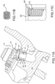
- corrosion mitigation device 1102 may be a threaded insert with a helical shape, such as a helical coil as illustrated in FIG. 11B .
- the corrosion mitigation device 1102 is inserted into threads of the boundary defining the void 908 of the second wheel portion 202, as illustrated in FIG. 11C , with the second portion 906 threading into the corrosion mitigation device 1102.
- the corrosion mitigation device 1102 is an anodic device or a desiccant device, among others that absorbs moisture to mitigate corrosion within the pneumatic port.
- the various embodiments provide a pneumatic port assembly that includes a corrosion mitigation device, such as an anodic device or a desiccant device, among others, to mitigate corrosion within the pneumatic port due to moisture that may enter areas of the pneumatic port.
- a corrosion mitigation device such as an anodic device or a desiccant device, among others, to mitigate corrosion within the pneumatic port due to moisture that may enter areas of the pneumatic port.
- the corrosion mitigation device may be in the form of a tubular shaped insert, an annular shaped insert, or a threaded insert, among others, that are easily replaceable during maintenance.
- the use of one or more of the corrosion mitigation devices described above may reduce maintenance, repair, and operation (MRO) costs and lead-times, increase the serviceable life of aircraft wheels, reduced scrap, and reduce replacement part demand.
- MRO maintenance, repair, and operation
- references to "one embodiment,” “an embodiment,” “various embodiments,” etc. indicate that the embodiment described may include a particular feature, structure, or characteristic, but every embodiment may not necessarily include the particular feature, structure, or characteristic. Moreover, such phrases are not necessarily referring to the same embodiment. Further, when a particular feature, structure, or characteristic is described in connection with an embodiment, it is submitted that it is within the knowledge of one skilled in the art to affect such feature, structure, or characteristic in connection with other embodiments whether or not explicitly described. After reading the description, it will be apparent to one skilled in the relevant art(s) how to implement the disclosure in alternative embodiments.
- Numbers, percentages, or other values stated herein are intended to include that value, and also other values that are about or approximately equal to the stated value, as would be appreciated by one of ordinary skill in the art encompassed by various embodiments of the present disclosure.
- a stated value should therefore be interpreted broadly enough to encompass values that are at least close enough to the stated value to perform a desired function or achieve a desired result.
- the stated values include at least the variation to be expected in a suitable industrial process, and may include values that are within 10%, within 5%, within 1%, within 0.1%, or within 0.01% of a stated value.
- the terms “substantially,” “about” or “approximately” as used herein represent an amount close to the stated amount that still performs a desired function or achieves a desired result.
- the term “substantially,” “about” or “approximately” may refer to an amount that is within 10% of, within 5% of, within 1% of, within 0.1 % of, and within 0.01% of a stated amount
Landscapes
- Engineering & Computer Science (AREA)
- Mechanical Engineering (AREA)
- Safety Valves (AREA)
Abstract
Description
- The present disclosure generally relates to pneumatic ports, and more particularly, to corrosion protection for aircraft wheel pneumatic ports.
- Many aircraft include landing gear for supporting the aircraft above a ground surface and for allowing the aircraft to move relative to the ground surface while remaining supported by the ground surface. Each landing gear may include one or more wheel assemblies that may each receive an aircraft tire. Each wheel assembly may be split wheel assemblies, for example, and may have an inboard wheel portion and an outboard wheel portion. Such wheel portions of a split wheel are often held together using a plurality of tie bolts. Each wheel assembly may include at least one pneumatic port, such as an inflation valve for inflating the aircraft tire, an over-inflation pressure relief valves to prevent over-inflation of the aircraft tire, and a tire pressure monitoring system (TPMS) sensor that may communicate wirelessly with a controller of the aircraft.
- A wheel assembly is disclosed herein. The wheel assembly includes a structure defining a wheel portion configured to receive a portion of a tire; and a structure of the wheel portion defining an air channel from a face of the wheel portion to an area that receives the portion of the tire, an end of the air channel proximate to the face being configured to receive a valve, wherein the structure is further configured to receive a corrosion mitigation device within the air channel.
- In various embodiments, the corrosion mitigation device is positioned in in an entry to the air channel, the entry being substantially near the face of the wheel portion, the air channel being configured to receive the valve, the corrosion mitigation device being located between the wheel assembly and the valve. In various embodiments, the corrosion mitigation device is annular shaped. In various embodiments, the corrosion mitigation device is positioned in an entry to the air channel substantially near the area that receives the portion of the tire. In various embodiments, the corrosion mitigation device is tubular shaped.
- In various embodiments, the corrosion mitigation device is configured to be positioned between threads of the wheel assembly configured to receive the valve and threads on an exterior of the valve. In various embodiments, the corrosion mitigation device is helically shaped to align with the threads of the wheel assembly and the threads on the exterior of the valve. In various embodiments, the corrosion mitigation device is an anodic device. In various embodiments, the corrosion mitigation device is a desiccant device.
- Also disclosed herein is a landing gear of an aircraft, including: a wheel assembly, the wheel assembly including: a structure defining a wheel portion configured to receive a portion of a tire; and a structure of the wheel portion defining an air channel from a face of the wheel portion to an area that receives the portion of the tire, an end of the air channel proximate to the face being configured to receive a valve, wherein the structure is further configured to receive a corrosion mitigation device within the air channel.
- In various embodiments, the corrosion mitigation device is positioned in in an entry to the air channel, the entry being substantially near the face of the wheel portion, the air channel being configured to receive the valve, the corrosion mitigation device being located between the wheel assembly and the valve. In various embodiments, the corrosion mitigation device is annular shaped. In various embodiments, the corrosion mitigation device is positioned in an entry to the air channel substantially near the area that receives the portion of the tire. In various embodiments, the corrosion mitigation device is tubular shaped.
- In various embodiments, the corrosion mitigation device is configured to be positioned between threads of the wheel assembly configured to receive the valve and threads on an exterior of the valve. In various embodiments, the corrosion mitigation device is helically shaped to align with the threads of the wheel assembly and the threads on the exterior of the valve. In various embodiments, the corrosion mitigation device is an anodic device. In various embodiments, the corrosion mitigation device is a desiccant device.
- Also disclosed herein is an aircraft including: a landing gear, where the landing gear includes a wheel assembly, the wheel assembly including: a structure defining a wheel portion configured to receive a portion of a tire; and a structure of the wheel portion defining an air channel from a face of the wheel portion to an area that receives the portion of the tire, an end of the air channel proximate to the face being configured to receive a valve, wherein the structure is further configured to receive a corrosion mitigation device within the air channel. In various embodiments, the corrosion mitigation device is an anodic device or a desiccant device.
- The foregoing features and elements may be combined in any combination, without exclusivity, unless expressly indicated herein otherwise. These features and elements as well as the operation of the disclosed embodiments will become more apparent in light of the following description and accompanying drawings.
- The subject matter of the present disclosure is particularly pointed out and distinctly claimed in the concluding portion of the specification. A more complete understanding of the present disclosure, however, may best be obtained by referring to the following detailed description and claims in connection with the following drawings. While the drawings illustrate various embodiments employing the principles described herein, the drawings do not limit the scope of the claims.
-
FIG. 1 illustrates an aircraft having multiple landing gear, in accordance with various embodiments. -
FIGS. 2A and2B illustrate a wheel assembly that includes a split wheel including of a first wheel portion and a second wheel portion, according to various embodiments. -
FIG. 3A illustrates a cross-sectional view of an inflation valve taken along section line B-B of the wheel assembly ofFIG. 2B , in accordance with various embodiments. -
FIG. 3B illustrates an isometric view of a corrosion mitigation device ofFIG. 3A , in accordance with various embodiments. -
FIG. 4A illustrates a cross-sectional view of an inflation valve taken along section line B-B of the wheel assembly ofFIG. 2B , in accordance with various embodiments. -
FIG. 4B illustrates an isometric view of a corrosion mitigation device ofFIG. 4A , in accordance with various embodiments. -
FIG. 5A illustrates a cross-sectional view of an inflation valve taken along section line B-B of the wheel assembly ofFIG. 2B , in accordance with various embodiments. -
FIGS. 5B and 5C illustrate a threaded corrosion mitigation device ofFIG. 5A , in accordance with various embodiments. -
FIG. 6A illustrates a cross-sectional view of the tire pressure monitoring system (TPMS) valve taken along section line C-C of the wheel assembly ofFIG. 2B , in accordance with various embodiments. -
FIG. 6B illustrates an isometric view of a corrosion mitigation device ofFIG. 6A , in accordance with various embodiments. -
FIG. 7A illustrates a cross-sectional view of the tire pressure monitoring system (TPMS) valve taken along section line C-C of the wheel assembly ofFIG. 2B , in accordance with various embodiments. -
FIG. 7B illustrates an isometric view of a corrosion mitigation device ofFIG. 7A , in accordance with various embodiments. -
FIG. 8A illustrates a cross-sectional view of the tire pressure monitoring system (TPMS) valve taken along section line C-C of the wheel assembly ofFIG. 2B , in accordance with various embodiments. -
FIGS. 8B and 8C illustrate a threaded corrosion mitigation device ofFIG. 8A , in accordance with various embodiments. -
FIG. 9A illustrates a cross-sectional view of the over-inflation pressure relief valve taken along section line D-D of the wheel assembly ofFIG. 2B , in accordance with various embodiments. -
FIG. 9B illustrates an isometric view of a corrosion mitigation device ofFIG. 9A , in accordance with various embodiments. -
FIG. 10A illustrates a cross-sectional view of the over-inflation pressure relief valve taken along section line D-D of the wheel assembly ofFIG. 2B , in accordance with various embodiments. -
FIG. 10B illustrates an isometric view of a corrosion mitigation device ofFIG. 10A , in accordance with various embodiments. -
FIG. 11A illustrates a cross-sectional view of the over-inflation pressure relief valve taken along section line D-D of the wheel assembly ofFIG. 2B , in accordance with various embodiments. -
FIGS. 11B and 11C illustrate a threaded corrosion mitigation device ofFIG. 11A , in accordance with various embodiments. - The following detailed description of various embodiments herein makes reference to the accompanying drawings, which show various embodiments by way of illustration. While these various embodiments are described in sufficient detail to enable those skilled in the art to practice the disclosure, it should be understood that other embodiments may be realized and that changes may be made without departing from the scope of the disclosure. Thus, the detailed description herein is presented for purposes of illustration only and not of limitation. Furthermore, any reference to singular includes plural embodiments, and any reference to more than one component or step may include a singular embodiment or step. Also, any reference to attached, fixed, connected, or the like may include permanent, removable, temporary, partial, full or any other possible attachment option. Additionally, any reference to without contact (or similar phrases) may also include reduced contact or minimal contact. It should also be understood that unless specifically stated otherwise, references to "a," "an" or "the" may include one or more than one and that reference to an item in the singular may also include the item in the plural. Further, all ranges may include upper and lower values and all ranges and ratio limits disclosed herein may be combined.
- Many aircraft include landing gear for supporting the aircraft above a ground surface and for allowing the aircraft to move relative to the ground surface while remaining supported by the ground surface. Each landing gear may include one or more wheel assemblies that may each receive an aircraft tire. Each wheel assembly may include at least one pneumatic port, such as an inflation valve for inflating the aircraft tire, an over-inflation pressure relief valves to prevent over-inflation of the aircraft tire, and a tire pressure monitoring system (TPMS) sensor that may communicate wirelessly with a controller of the aircraft. Corrosion in the pneumatic ports of an aircraft wheel is common due to difficulty in anodizing the pneumatic ports and an inability to apply primer and topcoat paint systems to surfaces associated with the pneumatic ports. Furthermore, superficial corrosion associated with a pneumatic port must be removed as part of maintenance; however, such corrosion is difficult to inspect and thus identify. If such corrosion goes undetected, corrosion pitting may occur that entails expensive rework or that may lead to cracking or scraping the aircraft wheel. The cause of corrosion is believed to be moisture that may be introduced during maintenance activities, which may enter the areas associated with the pneumatic ports.
- Disclosed herein is a pneumatic port assembly that includes a corrosion mitigation device, such as an anodic device or a desiccant device, among others. In various embodiments, the anodic device is a metal device that easily absorbs moisture that is present and corrodes thereby preventing corrosion of other parts of the pneumatic port assembly. That is, in various embodiments, the anodic device is metal substance that has a lower galvanic potential than the surrounding structure the anodic device protects. In that regard, the anodic device may be composed of less noble metals such as magnesium, zinc, beryllium, aluminum alloys, among others. In various embodiments, the desiccant device is a hygroscopic substance disposed within a structure that is used to induce or sustain a state of dryness (desiccation) in its vicinity. In various embodiments, the desiccant may be silica gel, activated charcoal, calcium sulfate, calcium chloride, molecular sieves, among others. In various embodiments, the corrosion mitigation device is added to the pneumatic port assembly to mitigate corrosion within the pneumatic port due to moisture that may enter areas of the pneumatic port. In various embodiments, the corrosion mitigation device may be in the form of a tubular shaped insert, an annular shaped insert, or a threaded insert, among others, that are easily replaceable during maintenance.
- Referring now to
FIG. 1 , anaircraft 100 in accordance with various embodiments can include multiple landing gear including afirst landing gear 110, asecond landing gear 120 and athird landing gear 130. Each landing gear may include one or more wheel assemblies 200 (FIG. 3 ). For example, thethird landing gear 130 may include an inner/inboard wheel assembly and an outer/outboard wheel assembly. Each wheel assembly of theaircraft 100 may be designed to receive a tire. For example, atire 136 may be placed about an outer circumference ofwheel assembly 200 and inflated. - Referring now to
FIGS. 2A and2B ,wheel assembly 200 includes a split wheel including of afirst wheel portion 201 and asecond wheel portion 202, according to various embodiments. That is,wheel assembly 200 may include a split wheel having multiple wheel portions, such as an inboard wheel portion and an outboard wheel portion.Wheel portions first wheel portion 201 may be referred to as an inboard wheel half and thesecond wheel portion 202 may be referred to as an outboard wheel half). Thewheel assembly 200 may be implemented with any landing gear of the aircraft 100 (e.g., any of the three landing gears mentioned above), and thewheel assembly 200 may be an inner/inboard wheel assembly or an outer/outboard assembly. Although numerous details are included herein pertaining to the implementation of thewheel assembly 200 in an aircraft, one skilled in the art will realize that a similar wheel assembly may be used in other vehicles, such as cars or motorcycles, and thus the scope of the present disclosure is not necessarily limited to aircraft wheel assemblies. - In various embodiments,
wheel assembly 200 also defines a tube-well 204. Tube-well 204 may be defined by respective flange sections of thefirst wheel portion 201 and thesecond wheel portion 202. Tube-well 204 may be configured to receive a tire and may form a seal with tire to allow pressurized air to inflate the tire. In various embodiments, thefirst wheel portion 201 also includes a radially outward extending lip or rim 208 located at an inboard end of thefirst wheel portion 201, and thesecond wheel portion 202 may also include a similar radially outward extending lip or rim 209 located at an outboard end of thesecond wheel portion 202. In various embodiments, aface 210 of thewheel assembly 200 may include one or more threaded portions to receive aninflation valve 211, over-inflationpressure relief valve 212, a tire pressure monitoring system (TPMS)valve 213, among others. - Referring now to
FIG. 3A , a cross-sectional view of theinflation valve 211 taken along section line B-B of thewheel assembly 200 ofFIG. 2B is illustrated, in accordance with various embodiments. In various embodiments, theinflation valve 211 may include apost 302 that includes afirst end 304 and asecond end 306. In various embodiments, thesecond end 306 may be removably fitted within a boundary defining avoid 308 of thesecond wheel portion 202, such as by threaded attachment. In various embodiments, thepost 302 may include anair channel 312, located generally along the long axis of thepost 302, that allows air to flow through thepost 302. In various embodiments, mounting of asecond end 306 of thepost 302 into the boundary defining thevoid 308 of thesecond wheel portion 202 may allow air to flow between theair channel 312 of thepost 302 andair channel 314 of thesecond wheel portion 202. In various embodiments, avalve core 316 may be removably mounted, such as by threading, within thefirst end 304 thepost 302. In various embodiments, thevalve core 316 may include a one-way valve that permits air to flow into theair channel 312 in one direction, but not the other. In the disclosed example, thevalve core 316 may allow air to flow into theair channel 312 through thefirst end 304 of thepost 302, but not in the other direction. In various embodiments, theinflation valve 211 may further includecorrosion mitigation device 318 disposed within theair channel 314 at thesecond end 306 ofpost 302. In various embodiments, thecorrosion mitigation device 318 is an annular shaped device that permits air to flow from theair channel 312 into theair channel 314. Referring temporarily toFIG. 3B , an isometric view of thecorrosion mitigation device 318 ofFIG. 3A is illustrated, in accordance with various embodiments. In various embodiments, thecorrosion mitigation device 318 is an anodic device or a desiccant device, among others that absorbs moisture to mitigate corrosion within the pneumatic port. - Referring now to
FIG. 4A , a cross-sectional view of theinflation valve 211 taken along section line B-B of thewheel assembly 200 ofFIG. 2B is illustrated, in accordance with various embodiments. In various embodiments, theinflation valve 211 may include apost 302 that includes afirst end 304 and asecond end 306. In various embodiments, thesecond end 306 may be removably fitted within a boundary defining avoid 308 of thesecond wheel portion 202, such as by threaded attachment. In various embodiments, thepost 302 may include anair channel 312, located generally along the long axis of thepost 302, that allows air to flow through thepost 302. In various embodiments, mounting of asecond end 306 of thepost 302 into the boundary defining thevoid 308 of thesecond wheel portion 202 may allow air to flow between theair channel 312 of thepost 302 andair channel 314 of thesecond wheel portion 202. In various embodiments, avalve core 316 may be removably mounted, such as by threading, within thefirst end 304 thepost 302. In various embodiments, thevalve core 316 may include a one-way valve that permits air to flow into theair channel 312 in one direction, but not the other. In the disclosed example, thevalve core 316 may allow air to flow into theair channel 312 through thefirst end 304 of thepost 302, but not in the other direction. In various embodiments,air channel 314 of thesecond wheel portion 202 includes afirst end 402 and asecond end 404. In various embodiments, acorrosion mitigation device 406 may be fitted into thesecond end 404 of theair channel 314 substantially near an area that receives at least a portion of a tire. In various embodiments, thecorrosion mitigation device 406 has a tubular shape that permits air coming from theair channel 312 through theair channel 314. Referring temporarily toFIG. 4B , an isometric view of thecorrosion mitigation device 406 ofFIG. 4A is illustrated, in accordance with various embodiments. In various embodiments, thecorrosion mitigation device 406 is an anodic device or a desiccant device, among others that absorbs moisture to mitigate corrosion within the pneumatic port. - Referring now to
FIG. 5A , a cross-sectional view of theinflation valve 211 taken along section line B-B of thewheel assembly 200 ofFIG. 2B is illustrated, in accordance with various embodiments. In various embodiments, theinflation valve 211 may include apost 302 that includes afirst end 304 and asecond end 306. In various embodiments, thesecond end 306 may be removably fitted within a boundary defining avoid 308 of thesecond wheel portion 202, such as by threaded attachment. In various embodiments, thepost 302 may include anair channel 312, located generally along the long axis of thepost 302, that allows air to flow through thepost 302. In various embodiments, mounting of asecond end 306 of thepost 302 into the boundary defining thevoid 308 of thesecond wheel portion 202 may allow air to flow between theair channel 312 of thepost 302 andair channel 314 of thesecond wheel portion 202. In various embodiments, avalve core 316 may be removably mounted, such as by threading, within thefirst end 304 thepost 302. In various embodiments, thevalve core 316 may include a one-way valve that permits air to flow into theair channel 312 in one direction, but not the other. In the disclosed example, thevalve core 316 may allow air to flow into theair channel 312 through thefirst end 304 of thepost 302, but not in the other direction. In various embodiments, theinflation valve 211 may further includecorrosion mitigation device 502. In various embodiments,corrosion mitigation device 502 may be a threaded insert with a helical shape, such as a helical coil as illustrated inFIG. 5B . Thecorrosion mitigation device 502 is inserted into threads of the boundary defining thevoid 308 of thesecond wheel portion 202, as illustrated inFIG. 5C , with thesecond end 306 of thepost 302 threading into thecorrosion mitigation device 502. In various embodiments, thecorrosion mitigation device 502 is an anodic device or a desiccant device, among others that absorbs moisture to mitigate corrosion within the pneumatic port. - Referring now to
FIG. 6A , a cross-sectional view of the tire pressure monitoring system (TPMS)valve 213 taken along section line C-C of thewheel assembly 200 ofFIG. 2B is illustrated, in accordance with various embodiments. In various embodiments, theTPMS valve 213 may include apressure protector valve 602 fluidly coupled to apressure duct 604. In various embodiments, thepressure protector valve 602 may be removably fitted within a boundary defining avoid 606 of thesecond wheel portion 202, such as by threaded attachment. In various embodiments, thepressure protector valve 602 may include anair channel 608, located generally along the long axis of thepressure protector valve 602, that allows air to flow through thepressure protector valve 602. In various embodiments, mounting of thepressure protector valve 602 into the boundary defining thevoid 606 of thesecond wheel portion 202 may allow air to flow between theair channel 608 of thepressure protector valve 602 andair channel 610 of thesecond wheel portion 202. In various embodiments, avalve core 612 may be removably mounted, such as by threading, within thepressure protector valve 602. In various embodiments, thevalve core 612 may include a one-way valve that permits air to flow into theair channel 608 in one direction, but not the other. In the disclosed example, thevalve core 612 may allow air to flow into theair channel 608 through thepressure protector valve 602, but not in the other direction. In various embodiments, thepressure protector valve 602 may further includecorrosion mitigation device 614 configured to be disposed proximate theair channel 610 when thepressure protector valve 602 is fluidly coupled to thepressure duct 604. In various embodiments, thecorrosion mitigation device 614 is annular shaped device that permits air to flow from theair channel 608 into theair channel 610. Referring temporarily toFIG. 6B , an isometric view of thecorrosion mitigation device 614 ofFIG. 3A is illustrated, in accordance with various embodiments. In various embodiments, thecorrosion mitigation device 614 is an anodic device or a desiccant device, among others that absorbs moisture to mitigate corrosion within the pneumatic port. - Referring now to
FIG. 7A , a cross-sectional view of the tire pressure monitoring system (TPMS)valve 213 taken along section line C-C of thewheel assembly 200 ofFIG. 2B is illustrated, in accordance with various embodiments. In various embodiments, theTPMS valve 213 may include apressure protector valve 602 fluidly coupled to apressure duct 604. In various embodiments, thepressure protector valve 602 may be removably fitted within a boundary defining avoid 606 of thesecond wheel portion 202, such as by threaded attachment. In various embodiments, thepressure protector valve 602 may include anair channel 608, located generally along the long axis of thepressure protector valve 602, that allows air to flow through thepressure protector valve 602. In various embodiments, mounting of thepressure protector valve 602 into the boundary defining thevoid 606 of thesecond wheel portion 202 may allow air to flow between theair channel 608 of thepressure protector valve 602 andair channel 610 of thesecond wheel portion 202. In various embodiments, avalve core 612 may be removably mounted, such as by threading, within thepressure protector valve 602. In various embodiments, thevalve core 612 may include a one-way valve that permits air to flow into theair channel 608 in one direction, but not the other. In the disclosed example, thevalve core 612 may allow air to flow into theair channel 608 through thepressure protector valve 602, but not in the other direction. In various embodiments,air channel 610 of thesecond wheel portion 202 includes afirst end 702 and asecond end 704. In various embodiments, acorrosion mitigation device 706 may be fitted into thesecond end 704 of theair channel 610 substantially near an area that receives at least a portion of a tire. In various embodiments, thecorrosion mitigation device 706 has a tubular shape that permits air to travel therethrough and through theair channel 610 and theair channel 608. Referring temporarily toFIG. 7B , an isometric view of thecorrosion mitigation device 706 ofFIG. 4A is illustrated, in accordance with various embodiments. In various embodiments, thecorrosion mitigation device 706 is an anodic device or a desiccant device, among others that absorbs moisture to mitigate corrosion within the pneumatic port. - Referring now to
FIG. 8A , a cross-sectional view of the tire pressure monitoring system (TPMS)valve 213 taken along section line C-C of thewheel assembly 200 ofFIG. 2B is illustrated, in accordance with various embodiments. In various embodiments, theTPMS valve 213 may include apressure protector valve 602 fluidly coupled to apressure duct 604. In various embodiments, thepressure protector valve 602 may be removably fitted within a boundary defining avoid 606 of thesecond wheel portion 202, such as by threaded attachment. In various embodiments, thepressure protector valve 602 may include anair channel 608, located generally along the long axis of thepressure protector valve 602, that allows air to flow through thepressure protector valve 602. In various embodiments, mounting of thepressure protector valve 602 into the boundary defining thevoid 606 of thesecond wheel portion 202 may allow air to flow between theair channel 608 of thepressure protector valve 602 andair channel 610 of thesecond wheel portion 202. In various embodiments, avalve core 612 may be removably mounted, such as by threading, within thepressure protector valve 602. In various embodiments, thevalve core 612 may include a one-way valve that permits air to flow into theair channel 608 in one direction, but not the other. In the disclosed example, thevalve core 612 may allow air to flow into theair channel 608 through thepressure protector valve 602, but not in the other direction. In various embodiments, thepressure protector valve 602 may further includecorrosion mitigation device 802. In various embodiments,corrosion mitigation device 802 may be a threaded insert with a helical shape, such as a helical coil as illustrated inFIG. 5B . Thecorrosion mitigation device 802 is inserted into threads of the boundary defining thevoid 606 of thesecond wheel portion 202, as illustrated inFIG. 5C , withvalve 602 threading into thecorrosion mitigation device 802. In various embodiments, thecorrosion mitigation device 802 is an anodic device or a desiccant device, among others that absorbs moisture to mitigate corrosion within the pneumatic port. - Referring now to
FIG. 9A , a cross-sectional view of the over-inflationpressure relief valve 212 taken along section line D-D of thewheel assembly 200 ofFIG. 2B is illustrated, in accordance with various embodiments. In various embodiments, the over-inflationpressure relief valve 212 may include apost 902 that includes afirst portion 904 and asecond portion 906. In various embodiments, thesecond portion 906 may be removably fitted within a boundary defining avoid 908 of thesecond wheel portion 202, such as by threaded attachment. In various embodiments, thepost 902 may include adiaphragm 910. In various embodiments, thediaphragm 910 is seated when the tire cavity air pressure is at or below the rated pressure for the tire. In various embodiments, when the tire cavity air pressure rises above a desired air pressure level in the tire, thediaphragm 910 rises allow in air to move from theair channel 912 of thesecond wheel portion 202 through theair channel 914 located generally along the long axis of thepost 902 and out throughboundaries defining voids 916 in thefirst portion 904 of thepost 902. In various embodiments, mounting of asecond portion 906 of thepost 902 into the boundary defining thevoid 908 of thesecond wheel portion 202 may allow air to flow between theair channel 914 of thepost 902 andair channel 912 of thesecond wheel portion 202. In various embodiments, over-inflationpressure relief valve 212 may further includecorrosion mitigation device 918 disposed at thesecond end 906 ofpost 902 within theair channel 912. In various embodiments, thecorrosion mitigation device 918 is annular shaped device that permits air to flow from theair channel 912 into theair channel 914. Referring temporarily toFIG. 9B , an isometric view of thecorrosion mitigation device 918 ofFIG. 9A is illustrated, in accordance with various embodiments. In various embodiments, thecorrosion mitigation device 918 is an anodic device or a desiccant device, among others that absorbs moisture to mitigate corrosion within the pneumatic port. - Referring now to
FIG. 10A , a cross-sectional view of the over-inflationpressure relief valve 212 taken along section line D-D of thewheel assembly 200 ofFIG. 2B is illustrated, in accordance with various embodiments. In various embodiments, the over-inflationpressure relief valve 212 may include apost 902 that includes afirst portion 904 and asecond portion 906. In various embodiments, thesecond portion 906 may be removably fitted within a boundary defining avoid 908 of thesecond wheel portion 202, such as by threaded attachment. In various embodiments, thepost 902 may include adiaphragm 910. In various embodiments, thediaphragm 910 is seated when the tire cavity air pressure is at or below the rated pressure for the tire. In various embodiments, when the tire cavity air pressure rises above a desired air pressure level in the tire, thediaphragm 910 rises allow in air to move from theair channel 912 of thesecond wheel portion 202 through theair channel 914 located generally along the long axis of thepost 902 and out throughboundaries defining voids 916 in thefirst portion 904 of thepost 902. In various embodiments, mounting of asecond portion 906 of thepost 902 into the boundary defining thevoid 908 of thesecond wheel portion 202 may allow air to flow between theair channel 914 of thepost 902 andair channel 912 of thesecond wheel portion 202. In various embodiments,air channel 912 of thesecond wheel portion 202 includes afirst end 1002 and asecond end 1004. In various embodiments, acorrosion mitigation device 1006 may be fitted into thesecond end 1004 of theair channel 912 substantially near an area that receives at least a portion of a tire. In various embodiments, thecorrosion mitigation device 1006 has a tubular shape that permits air to flow therethrough and through theair channel 912 and into theair channel 914. Referring temporarily toFIG. 10B , an isometric view of thecorrosion mitigation device 1006 ofFIG. 10A is illustrated, in accordance with various embodiments. In various embodiments, thecorrosion mitigation device 1006 is an anodic device or a desiccant device, among others that absorbs moisture to mitigate corrosion within the pneumatic port. - Referring now to
FIG. 11A , a cross-sectional view of the over-inflationpressure relief valve 212 taken along section line D-D of thewheel assembly 200 ofFIG. 2B is illustrated, in accordance with various embodiments. In various embodiments, the over-inflationpressure relief valve 212 may include apost 902 that includes afirst portion 904 and asecond portion 906. In various embodiments, thesecond portion 906 may be removably fitted within a boundary defining avoid 908 of thesecond wheel portion 202, such as by threaded attachment. In various embodiments, thepost 902 may include adiaphragm 910. In various embodiments, thediaphragm 910 is seated when the tire cavity air pressure is at or below the rated pressure for the tire. In various embodiments, when the tire cavity air pressure rises above a desired air pressure level in the tire, thediaphragm 910 rises allow in air to move from theair channel 912 of thesecond wheel portion 202 through theair channel 914 located generally along the long axis of thepost 902 and out throughboundaries defining voids 916 in thefirst portion 904 of thepost 902. In various embodiments, mounting of asecond portion 906 of thepost 902 into the boundary defining thevoid 908 of thesecond wheel portion 202 may allow air to flow between theair channel 914 of thepost 902 andair channel 912 of thesecond wheel portion 202. In various embodiments, the over-inflationpressure relief valve 212 may further includecorrosion mitigation device 1102. In various embodiments,corrosion mitigation device 1102 may be a threaded insert with a helical shape, such as a helical coil as illustrated inFIG. 11B . Thecorrosion mitigation device 1102 is inserted into threads of the boundary defining thevoid 908 of thesecond wheel portion 202, as illustrated inFIG. 11C , with thesecond portion 906 threading into thecorrosion mitigation device 1102. In various embodiments, thecorrosion mitigation device 1102 is an anodic device or a desiccant device, among others that absorbs moisture to mitigate corrosion within the pneumatic port. - Thus, the various embodiments provide a pneumatic port assembly that includes a corrosion mitigation device, such as an anodic device or a desiccant device, among others, to mitigate corrosion within the pneumatic port due to moisture that may enter areas of the pneumatic port. In various embodiments, the corrosion mitigation device may be in the form of a tubular shaped insert, an annular shaped insert, or a threaded insert, among others, that are easily replaceable during maintenance. In various embodiments, the use of one or more of the corrosion mitigation devices described above, may reduce maintenance, repair, and operation (MRO) costs and lead-times, increase the serviceable life of aircraft wheels, reduced scrap, and reduce replacement part demand.
- Benefits, other advantages, and solutions to problems have been described herein with regard to specific embodiments. Furthermore, the connecting lines shown in the various figures contained herein are intended to represent exemplary functional relationships and/or physical couplings between the various elements. It should be noted that many alternative or additional functional relationships or physical connections may be present in a practical system. However, the benefits, advantages, solutions to problems, and any elements that may cause any benefit, advantage, or solution to occur or become more pronounced are not to be construed as critical, required, or essential features or elements of the disclosure. The scope of the disclosure is accordingly to be limited by nothing other than the appended claims, in which reference to an element in the singular is not intended to mean "one and only one" unless explicitly so stated, but rather "one or more." Moreover, where a phrase similar to "at least one of A, B, or C" is used in the claims, it is intended that the phrase be interpreted to mean that A alone may be present in an embodiment, B alone may be present in an embodiment, C alone may be present in an embodiment, or that any combination of the elements A, Band C may be present in a single embodiment; for example, A and B, A and C, B and C, or A and B and C. Different cross-hatching is used throughout the figures to denote different parts but not necessarily to denote the same or different materials.
- Systems, methods, and apparatus are provided herein. In the detailed description herein, references to "one embodiment," "an embodiment," "various embodiments," etc., indicate that the embodiment described may include a particular feature, structure, or characteristic, but every embodiment may not necessarily include the particular feature, structure, or characteristic. Moreover, such phrases are not necessarily referring to the same embodiment. Further, when a particular feature, structure, or characteristic is described in connection with an embodiment, it is submitted that it is within the knowledge of one skilled in the art to affect such feature, structure, or characteristic in connection with other embodiments whether or not explicitly described. After reading the description, it will be apparent to one skilled in the relevant art(s) how to implement the disclosure in alternative embodiments.
- Numbers, percentages, or other values stated herein are intended to include that value, and also other values that are about or approximately equal to the stated value, as would be appreciated by one of ordinary skill in the art encompassed by various embodiments of the present disclosure. A stated value should therefore be interpreted broadly enough to encompass values that are at least close enough to the stated value to perform a desired function or achieve a desired result. The stated values include at least the variation to be expected in a suitable industrial process, and may include values that are within 10%, within 5%, within 1%, within 0.1%, or within 0.01% of a stated value. Additionally, the terms "substantially," "about" or "approximately" as used herein represent an amount close to the stated amount that still performs a desired function or achieves a desired result. For example, the term "substantially," "about" or "approximately" may refer to an amount that is within 10% of, within 5% of, within 1% of, within 0.1 % of, and within 0.01% of a stated amount or value.
- Furthermore, no element, component, or method step in the present disclosure is intended to be dedicated to the public regardless of whether the element, component, or method step is explicitly recited in the claims. As used herein, the terms "comprises," "comprising," or any other variation thereof, are intended to cover a non-exclusive inclusion, such that a process, method, article, or apparatus that comprises a list of elements does not include only those elements but may include other elements not expressly listed or inherent to such process, method, article, or apparatus.
- Finally, it should be understood that any of the above-described concepts can be used alone or in combination with any or all of the other above-described concepts. Although various embodiments have been disclosed and described, one of ordinary skill in this art would recognize that certain modifications would come within the scope of this disclosure. Accordingly, the description is not intended to be exhaustive or to limit the principles described or illustrated herein to any precise form. Many modifications and variations are possible in light of the above teaching.
Claims (15)
- A wheel assembly, comprising:a structure defining a wheel portion (202) configured to receive a portion of a tire; anda structure of the wheel portion (202) defining an air channel from a face of the wheel portion (202) to an area that receives the portion of the tire, an end of the air channel proximate to the face being configured to receive a valve, wherein the structure is further configured to receive a corrosion mitigation device within the air channel.
- The wheel assembly of claim 1, wherein the corrosion mitigation device is positioned in in an entry to the air channel, the entry being substantially near the face of the wheel portion (202), the air channel being configured to receive the valve, the corrosion mitigation device being located between the wheel assembly and the valve.
- The wheel assembly of claim 2, wherein the corrosion mitigation device is annular shaped.
- The wheel assembly of any preceding claim, wherein the corrosion mitigation device is positioned in an entry to the air channel substantially near the area that receives the portion of the tire.
- The wheel assembly of claim 4, wherein the corrosion mitigation device is tubular shaped.
- The wheel assembly of any preceding claim, wherein the corrosion mitigation device is configured to be positioned between threads of the wheel assembly configured to receive the valve and threads on an exterior of the valve, and optionally wherein the corrosion mitigation device is helically shaped to align with the threads of the wheel assembly and the threads on the exterior of the valve.
- The wheel assembly of any preceding claim, wherein the corrosion mitigation device is an anodic device, or wherein the corrosion mitigation device is a desiccant device.
- A landing gear of an aircraft, comprising:
a wheel assembly, the wheel assembly comprising:a structure defining a wheel portion (202) configured to receive a portion of a tire; anda structure of the wheel portion (202) defining an air channel from a face of the wheel portion (202) to an area that receives the portion of the tire, an end of the air channel proximate to the face being configured to receive a valve, wherein the structure is further configured to receive a corrosion mitigation device within the air channel. - The landing gear of claim 8, wherein the corrosion mitigation device is positioned in in an entry to the air channel, the entry being substantially near the face of the wheel portion (202), the air channel being configured to receive the valve, the corrosion mitigation device being located between the wheel assembly and the valve.
- The landing gear of claim 9, wherein the corrosion mitigation device is annular shaped.
- The landing gear of claim 8 or 9, wherein the corrosion mitigation device is positioned in an entry to the air channel substantially near the area that receives the portion of the tire, and optionally wherein the corrosion mitigation device is tubular shaped.
- The landing gear of any of claims 8 to 11, wherein the corrosion mitigation device is configured to be positioned between threads of the wheel assembly configured to receive the valve and threads on an exterior of the valve, and optionally wherein the corrosion mitigation device is helically shaped to align with the threads of the wheel assembly and the threads on the exterior of the valve.
- The landing gear of any of claims 8 to 12, wherein the corrosion mitigation device is an anodic device, or wherein the corrosion mitigation device is a desiccant device.
- An aircraft comprising:
a landing gear, wherein the landing gear comprises a wheel assembly, the wheel assembly comprising:a structure defining a wheel portion (202) configured to receive a portion of a tire; anda structure of the wheel portion (202) defining an air channel from a face of the wheel portion (202) to an area that receives the portion of the tire, an end of the air channel proximate to the face being configured to receive a valve, wherein the structure is further configured to receive a corrosion mitigation device within the air channel. - The aircraft of claim 14, wherein the corrosion mitigation device is an anodic device or a desiccant device.
Applications Claiming Priority (1)
| Application Number | Priority Date | Filing Date | Title |
|---|---|---|---|
| US18/083,259 US12576677B2 (en) | 2022-12-16 | 2022-12-16 | Corrosion protection for aircraft wheel pneumatic ports |
Publications (1)
| Publication Number | Publication Date |
|---|---|
| EP4385751A1 true EP4385751A1 (en) | 2024-06-19 |
Family
ID=89119348
Family Applications (1)
| Application Number | Title | Priority Date | Filing Date |
|---|---|---|---|
| EP23214389.1A Pending EP4385751A1 (en) | 2022-12-16 | 2023-12-05 | Corrosion protection for aircraft wheel pneumatic ports |
Country Status (2)
| Country | Link |
|---|---|
| US (1) | US12576677B2 (en) |
| EP (1) | EP4385751A1 (en) |
Citations (5)
| Publication number | Priority date | Publication date | Assignee | Title |
|---|---|---|---|---|
| GB836286A (en) * | 1957-02-18 | 1960-06-01 | Bendix Aviat Corp | Tire inflating valve for aircraft wheel |
| EP0547848B1 (en) * | 1991-12-14 | 1995-09-06 | Sumitomo Rubber Industries Limited | Improved inflation device for a pneumatic tyre |
| US20050178437A1 (en) * | 2004-02-17 | 2005-08-18 | Schrader-Bridgeport International, Inc. | Pressure relief valve embedded in a molded rubber seal |
| US20180126806A1 (en) * | 2015-03-24 | 2018-05-10 | Alligator Ventilfabrik Gmbh | Air pressure measuring device for a vehicle tire and method for assembling the air pressure measuring device |
| US20220388356A1 (en) * | 2019-12-10 | 2022-12-08 | Safran Landing Systems | Wheel comprising an internal inflation channel, landing gear and an aircraft comprising such a wheel |
Family Cites Families (12)
| Publication number | Priority date | Publication date | Assignee | Title |
|---|---|---|---|---|
| US2744559A (en) * | 1953-02-11 | 1956-05-08 | Dill Mfg Co | Tubeless tire valve stem |
| US2871905A (en) | 1957-02-18 | 1959-02-03 | Bendix Aviat Corp | Tire inflating valve for aircraft wheel |
| GB892331A (en) * | 1957-08-20 | 1962-03-28 | Dunlop Rubber Co | Improvements in or relating to inflation valve assemblies and adaptors for pneumatictyres |
| JPS5339922Y2 (en) * | 1975-10-04 | 1978-09-27 | ||
| US4064923A (en) * | 1976-04-13 | 1977-12-27 | Eaton Corporation | Tire valve assembly |
| CH642305A5 (en) * | 1980-01-22 | 1984-04-13 | Fischer Ag Georg | ONE-PIECE MOLDED BOTTOM RIM FOR A TUBELESS MOTORCYCLE WHEEL. |
| US4793374A (en) * | 1987-04-15 | 1988-12-27 | Bridge Products, Inc. | Corrosion resistant tire valve assembly and components thereof |
| US5844131A (en) * | 1995-06-26 | 1998-12-01 | Alligator Ventilfabrik Gmbh | Tire pressure sensor apparatus for a pneumatic tire of a vehicle |
| WO2004091934A1 (en) | 2003-04-18 | 2004-10-28 | Freni Brembo S.P.A. | Wheel for vehicles |
| US20070017595A1 (en) * | 2005-07-23 | 2007-01-25 | Michael Arno | Tire fill nozzle and dryer |
| DE202006005269U1 (en) * | 2006-03-30 | 2006-08-31 | Alligator Ventilfabrik Gmbh | Tire valve, comprising special arrangement of sealing element and wider valve segments |
| FR2947214B1 (en) * | 2009-06-25 | 2012-12-14 | Schrader Sas | ASYMMETRIC VALVE FOR VEHICLE WHEEL |
-
2022
- 2022-12-16 US US18/083,259 patent/US12576677B2/en active Active
-
2023
- 2023-12-05 EP EP23214389.1A patent/EP4385751A1/en active Pending
Patent Citations (5)
| Publication number | Priority date | Publication date | Assignee | Title |
|---|---|---|---|---|
| GB836286A (en) * | 1957-02-18 | 1960-06-01 | Bendix Aviat Corp | Tire inflating valve for aircraft wheel |
| EP0547848B1 (en) * | 1991-12-14 | 1995-09-06 | Sumitomo Rubber Industries Limited | Improved inflation device for a pneumatic tyre |
| US20050178437A1 (en) * | 2004-02-17 | 2005-08-18 | Schrader-Bridgeport International, Inc. | Pressure relief valve embedded in a molded rubber seal |
| US20180126806A1 (en) * | 2015-03-24 | 2018-05-10 | Alligator Ventilfabrik Gmbh | Air pressure measuring device for a vehicle tire and method for assembling the air pressure measuring device |
| US20220388356A1 (en) * | 2019-12-10 | 2022-12-08 | Safran Landing Systems | Wheel comprising an internal inflation channel, landing gear and an aircraft comprising such a wheel |
Also Published As
| Publication number | Publication date |
|---|---|
| US20240198741A1 (en) | 2024-06-20 |
| US12576677B2 (en) | 2026-03-17 |
Similar Documents
| Publication | Publication Date | Title |
|---|---|---|
| US8505600B2 (en) | Integrated rotary union and hub cap | |
| US8146413B1 (en) | Two-port tire valve stem | |
| CN104040455B (en) | Axletree aerating system | |
| EP2544906B1 (en) | Vehicle wheel assemblies and valves for use with a central tire inflation system | |
| US7731300B2 (en) | Hubcap for heavy-duty vehicles | |
| EP2974892B1 (en) | Tire inflation system having a pressure relief valve | |
| US9358845B2 (en) | Wheel apparatus | |
| US10436266B2 (en) | Brake mounting hardware with integrated axle vent system | |
| US20200231001A1 (en) | Deflation safety system and system including same | |
| EP4385751A1 (en) | Corrosion protection for aircraft wheel pneumatic ports | |
| EP4253085A2 (en) | Reusable rim for non-pneumatic tires | |
| EP3946968B1 (en) | Bolt together wheel with deflation system | |
| AU2006287899B2 (en) | Hubcap for heavy-duty vehicles | |
| WO2009103044A1 (en) | Tire inflation system | |
| US20110056602A1 (en) | Rigid air valve | |
| WO2018017050A1 (en) | Pneumatic tire with sealing piece for tubeless tires installed on multi-piece wheels | |
| CN101687450A (en) | Purge valve for mounted assembly | |
| JP5180779B2 (en) | Temporary tire and its installation structure |
Legal Events
| Date | Code | Title | Description |
|---|---|---|---|
| PUAI | Public reference made under article 153(3) epc to a published international application that has entered the european phase |
Free format text: ORIGINAL CODE: 0009012 |
|
| STAA | Information on the status of an ep patent application or granted ep patent |
Free format text: STATUS: THE APPLICATION HAS BEEN PUBLISHED |
|
| AK | Designated contracting states |
Kind code of ref document: A1 Designated state(s): AL AT BE BG CH CY CZ DE DK EE ES FI FR GB GR HR HU IE IS IT LI LT LU LV MC ME MK MT NL NO PL PT RO RS SE SI SK SM TR |
|
| STAA | Information on the status of an ep patent application or granted ep patent |
Free format text: STATUS: REQUEST FOR EXAMINATION WAS MADE |
|
| 17P | Request for examination filed |
Effective date: 20241218 |
|
| GRAP | Despatch of communication of intention to grant a patent |
Free format text: ORIGINAL CODE: EPIDOSNIGR1 |
|
| STAA | Information on the status of an ep patent application or granted ep patent |
Free format text: STATUS: GRANT OF PATENT IS INTENDED |
|
| RIC1 | Information provided on ipc code assigned before grant |
Ipc: B60B 19/08 20060101AFI20251105BHEP Ipc: B60B 21/02 20060101ALI20251105BHEP Ipc: B60C 29/06 20060101ALI20251105BHEP Ipc: B60B 3/00 20060101ALN20251105BHEP Ipc: B60B 25/00 20060101ALN20251105BHEP Ipc: B60C 29/02 20060101ALN20251105BHEP |
|
| INTG | Intention to grant announced |
Effective date: 20251125 |
|
| GRAJ | Information related to disapproval of communication of intention to grant by the applicant or resumption of examination proceedings by the epo deleted |
Free format text: ORIGINAL CODE: EPIDOSDIGR1 |
|
| STAA | Information on the status of an ep patent application or granted ep patent |
Free format text: STATUS: REQUEST FOR EXAMINATION WAS MADE |
|
| INTC | Intention to grant announced (deleted) | ||
| GRAP | Despatch of communication of intention to grant a patent |
Free format text: ORIGINAL CODE: EPIDOSNIGR1 |
|
| STAA | Information on the status of an ep patent application or granted ep patent |
Free format text: STATUS: GRANT OF PATENT IS INTENDED |
|
| RIC1 | Information provided on ipc code assigned before grant |
Ipc: B60B 19/08 20060101AFI20260310BHEP Ipc: B60B 21/02 20060101ALI20260310BHEP Ipc: B60C 29/06 20060101ALI20260310BHEP Ipc: B60B 3/00 20060101ALN20260310BHEP Ipc: B60B 25/00 20060101ALN20260310BHEP Ipc: B60C 29/02 20060101ALN20260310BHEP |