EP4385681A1 - Suction pad - Google Patents
Suction pad Download PDFInfo
- Publication number
- EP4385681A1 EP4385681A1 EP23214510.2A EP23214510A EP4385681A1 EP 4385681 A1 EP4385681 A1 EP 4385681A1 EP 23214510 A EP23214510 A EP 23214510A EP 4385681 A1 EP4385681 A1 EP 4385681A1
- Authority
- EP
- European Patent Office
- Prior art keywords
- workpiece
- pressure
- suction pad
- cavities
- cavity
- Prior art date
- Legal status (The legal status is an assumption and is not a legal conclusion. Google has not performed a legal analysis and makes no representation as to the accuracy of the status listed.)
- Granted
Links
Images



Classifications
-
- B—PERFORMING OPERATIONS; TRANSPORTING
- B25—HAND TOOLS; PORTABLE POWER-DRIVEN TOOLS; MANIPULATORS
- B25J—MANIPULATORS; CHAMBERS PROVIDED WITH MANIPULATION DEVICES
- B25J15/00—Gripping heads and other end effectors
- B25J15/06—Gripping heads and other end effectors with vacuum or magnetic holding means
- B25J15/0616—Gripping heads and other end effectors with vacuum or magnetic holding means with vacuum
- B25J15/0625—Gripping heads and other end effectors with vacuum or magnetic holding means with vacuum provided with a valve
- B25J15/0633—Air-flow-actuated valves
-
- B—PERFORMING OPERATIONS; TRANSPORTING
- B65—CONVEYING; PACKING; STORING; HANDLING THIN OR FILAMENTARY MATERIAL
- B65G—TRANSPORT OR STORAGE DEVICES, e.g. CONVEYORS FOR LOADING OR TIPPING, SHOP CONVEYOR SYSTEMS OR PNEUMATIC TUBE CONVEYORS
- B65G47/00—Article or material-handling devices associated with conveyors; Methods employing such devices
- B65G47/74—Feeding, transfer, or discharging devices of particular kinds or types
- B65G47/90—Devices for picking-up and depositing articles or materials
- B65G47/91—Devices for picking-up and depositing articles or materials incorporating pneumatic, e.g. suction, grippers
-
- B—PERFORMING OPERATIONS; TRANSPORTING
- B25—HAND TOOLS; PORTABLE POWER-DRIVEN TOOLS; MANIPULATORS
- B25B—TOOLS OR BENCH DEVICES NOT OTHERWISE PROVIDED FOR, FOR FASTENING, CONNECTING, DISENGAGING, OR HOLDING
- B25B11/00—Work holders not covered by any preceding group in the subclass, e.g. magnetic work holders, vacuum work holders
- B25B11/005—Vacuum work holders
-
- B—PERFORMING OPERATIONS; TRANSPORTING
- B25—HAND TOOLS; PORTABLE POWER-DRIVEN TOOLS; MANIPULATORS
- B25J—MANIPULATORS; CHAMBERS PROVIDED WITH MANIPULATION DEVICES
- B25J13/00—Controls for manipulators
- B25J13/08—Controls for manipulators by means of sensing devices, e.g. viewing or touching devices
- B25J13/087—Controls for manipulators by means of sensing devices, e.g. viewing or touching devices for sensing other physical parameters, e.g. electrical or chemical properties
-
- B—PERFORMING OPERATIONS; TRANSPORTING
- B25—HAND TOOLS; PORTABLE POWER-DRIVEN TOOLS; MANIPULATORS
- B25J—MANIPULATORS; CHAMBERS PROVIDED WITH MANIPULATION DEVICES
- B25J15/00—Gripping heads and other end effectors
- B25J15/06—Gripping heads and other end effectors with vacuum or magnetic holding means
- B25J15/0616—Gripping heads and other end effectors with vacuum or magnetic holding means with vacuum
- B25J15/0625—Gripping heads and other end effectors with vacuum or magnetic holding means with vacuum provided with a valve
-
- B—PERFORMING OPERATIONS; TRANSPORTING
- B25—HAND TOOLS; PORTABLE POWER-DRIVEN TOOLS; MANIPULATORS
- B25J—MANIPULATORS; CHAMBERS PROVIDED WITH MANIPULATION DEVICES
- B25J15/00—Gripping heads and other end effectors
- B25J15/06—Gripping heads and other end effectors with vacuum or magnetic holding means
- B25J15/0616—Gripping heads and other end effectors with vacuum or magnetic holding means with vacuum
- B25J15/0691—Suction pad made out of porous material, e.g. sponge or foam
Definitions
- the present invention relates to a suction pad for sucking a workpiece using vacuum pressure, and more particularly to a suction pad capable of confirming the suction state of the workpiece.
- a suction pad that sucks a workpiece by bringing a sponge member made of a porous material into contact with the workpiece and generating vacuum pressure inside the sponge member.
- a technique for detecting the suction state of a workpiece by detecting pressure in a path through which vacuum pressure is introduced into a suction pad.
- JP 2022-017935 A discloses a suction pad including an inner sponge pad formed of an open cell sponge having air permeability, and an outer sponge pad formed of a closed cell sponge having no air permeability.
- a pressure sensor is disposed on a path through which the suction pad is connected to an ejector, and the suction state of the workpiece sucked by the inner sponge pad and the suction state of the workpiece sucked by the outer sponge pad are sequentially detected.
- check valves flow passage adjustment valves
- a vacuum suction device that includes a plurality of suction portions (suction pads) and is capable of sucking workpieces of various sizes
- check valves flow passage adjustment valves
- the vacuum pressure required for sucking the workpiece acts on the workpiece effectively.
- a large sponge pad including a large number of suction holes is used to suck workpieces of various sizes, it is desirable to dispose check valves as well.
- the suction state of the workpiece cannot be easily confirmed by simply disposing the pressure sensor. This is because, since the vacuum pressure is maintained by the action of the check valves regardless of whether the workpiece is being sucked or is not being sucked, there is no difference between the pressures detected by the pressure sensor, and the state where the workpiece is being sucked and the state where the workpiece is not being sucked cannot be distinguished from each other.
- the present invention has the object of solving the aforementioned problem.
- the present invention provides a suction pad comprising: a body; and a sponge member, wherein the body includes a negative pressure chamber, and a plurality of communication passages configured to communicate with the negative pressure chamber, and the sponge member includes a plurality of cavities configured to open toward a workpiece and communicate with the negative pressure chamber through the communication passages.
- a flow passage adjustment valve configured to adjust a flow passage area is disposed in each of the communication passages, and when vacuum pressure is generated in the negative pressure chamber and a cavity among the plurality of cavities is not closed by the workpiece, a flow passage area of a communication passage among the communication passages that corresponds to the cavity that is not closed by the workpiece is adjusted to be decreased.
- the suction pad further comprises a pressure detection port configured to detect pressure in at least one cavity among the plurality of cavities.
- the suction pad according to the present invention has a structure in which the flow passage adjustment valves are disposed in the communication passages connecting the cavities of the sponge member to the negative pressure chamber, and includes the pressure detection port for detecting the pressure in at least one cavity of the sponge member. Therefore, it is possible to easily confirm whether or not the workpiece is being sucked.
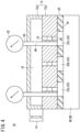
- FIG. 1 A suction pad 10 according to a first embodiment of the present invention will be described with reference to FIGS. 1 to 5 .
- the suction pad 10 includes a body 12 and a sponge member 20.
- the suction pad 10 when terms in relation to upper and lower directions are used, such terms refer to the directions shown in the drawings, however, the actual arrangement of the respective constituent members is not limited thereby.
- the body 12 is formed of a main body 12a that has a box shape and opens downward, and a plate 12b that is thick and covers the main body 12a from below.
- the main body 12a includes a suction port 14 connected to a vacuum generator (not shown).
- the body 12 includes therein a negative pressure chamber 16 communicating with the suction port 14.
- the plate 12b includes a plurality of communication passages 18 communicating with the negative pressure chamber 16.
- the sponge member 20 having a plate shape is attached to a lower surface of the plate 12b by means of bonding or the like.
- the sponge member 20 includes a plurality of cavities 22 opening toward a workpiece W.
- the cavities 22 of the sponge member 20 communicate with the negative pressure chamber 16 through the communication passages 18 of the plate 12b.
- the sponge member 20 comes into contact with the workpiece W at a lower surface (bottom surface) 24 thereof.
- the sponge member 20 is made of a material having a semi-open and semi-closed cell structure, and is manufactured by foam-molding ethylene propylene rubber (EPDM), for example.
- EPDM ethylene propylene rubber
- the sponge member 20 exhibits flexibility which is a property of open cells until it is compressed by a predetermined amount from a natural state, and exhibits airtightness which is a property of closed cells after it is compressed by the predetermined amount.
- the sponge member 20 can be deformed in accordance with the surface shape of the workpiece W by exhibiting flexibility. Even if the workpiece W has irregularities on its surface as in the case of a cardboard box in which beverage containers are packaged, no gap is generated between the sponge member 20 and the workpiece W. The sponge member 20 comes into close contact with the workpiece W and then exhibits airtightness to cause vacuum pressure required for sucking the workpiece W to act on the workpiece W.
- the thickness of the sponge member 20 when no vertical compressive force is applied to the sponge member 20 is represented by T0, and the thickness of the sponge member 20 when a vertical compressive force is applied to the sponge member 20 is represented by T.
- a compression amount (%) of the sponge member 20 is defined as (T0 - T)/T0 ⁇ 100.
- the sponge member 20 exhibits sufficient airtightness when compressed to a compression amount of at least about 70 %, for example.
- a flow passage adjustment valve 26 is arranged in the middle of each communication passage 18 of the body 12.
- the flow passage adjustment valve 26 adjusts the flow passage area of the communication passage 18 in accordance with the suction state of the workpiece W.
- the flow passage area of the communication passage 18 is sufficiently increased, and the pressure in the cavity 22 becomes equal to the pressure in the negative pressure chamber 16. That is, when the cavity 22 is closed by the workpiece W, the same vacuum pressure as the vacuum pressure generated in the negative pressure chamber 16 is generated in the cavity 22.
- the flow passage area of the communication passage 18 is sufficiently decreased, and high vacuum pressure is generated in the negative pressure chamber 16, while the pressure in the cavity 22 becomes substantially equal to the atmospheric pressure.
- the flow passage adjustment valve 26 includes a first joint member 28, a second joint member 32, and a valve element 36.
- the tubular valve element 36 is disposed inside the tubular first joint member 28, and can be vertically displaced with respect to the first joint member 28.
- the first joint member 28 is provided with a tapered seat portion 30 against which a head part 38 of the valve element 36 can abut.
- the tubular second joint member 32 is connected and fixed to the first joint member 28.
- a stopper 34 capable of abutting against a lower end of the valve element 36 is attached to the second joint member 32. By the valve element 36 abutting against the stopper 34, downward displacement of the valve element 36 is regulated.
- the head part 38 of the valve element 36 includes an orifice 40 at its center, and the orifice 40 communicates with an inner space 44 of the valve element 36.
- a sidewall of the valve element 36 includes a plurality of openings 42 that communicate with the inner space 44 of the valve element 36. The area of the opening 42 is sufficiently larger than the area of the orifice 40.
- the inner space 44 of the valve element 36 communicates, at the lower end thereof, with an internal space of the second joint member 32.
- a spring 46 for biasing the valve element 36 downward is disposed between the first joint member 28 and the valve element 36.
- the suction pad 10 can suck workpieces W of various sizes.
- the pressure in the negative pressure chamber 16 of the body 12 does not increase even if the workpiece W is small enough to contact only a part of the bottom surface 24 of the sponge member 20 and one or some of the cavities 22 of the sponge member 20 are open to the atmosphere. That is, even if there is a cavity 22 which is not closed by the workpiece W, the vacuum pressure generated in the negative pressure chamber 16 does not decrease due to the action of the flow passage adjustment valve 26.
- the body 12 includes a detection passage 48 for detecting the pressure in a predetermined cavity 22 of the sponge member 20.
- the detection passage 48 is arranged for each of one or more selected cavities 22.
- the detection passage 48 vertically passes through the negative pressure chamber 16 and extends from an upper surface to a lower surface of the body 12, and a lower end of the detection passage 48 communicates with the corresponding cavity 22.
- An upper end of each detection passage 48 forms a pressure detection port 50.
- a pressure sensor 52 is individually connected to each pressure detection port 50. The pressure in the selected cavity 22 is detected by the pressure sensor 52.
- the cavity 22 for which the detection passage 48 is correspondingly arranged is determined in consideration of the size of the workpiece W to be sucked.
- the detection passages 48 are arranged corresponding to one or more cavities 22 closed by the workpiece W, and one or more cavities 22 that are not closed by the workpiece W.
- FIG. 1 shows three cavities 22a to 22c.
- the detection passages 48 and the pressure sensors 52 are arranged corresponding to the cavity 22a and the cavity 22c among the three cavities.
- the suction pad 10 is used by being attached to, for example, a conveying device (not shown).
- a host controller such as a PLC
- the conveying device is driven and the suction pad 10 comes into contact with the workpiece W.
- air in the negative pressure chamber 16 is sucked from the suction port 14 toward the vacuum generator.
- the flow passage areas of the communication passages 18 are reduced by the flow passage adjustment valves 26. Therefore, high vacuum pressure is easily generated in the negative pressure chamber 16.
- the cavity 22a and the cavity 22b are closed by the workpiece W1, and the cavity 22c is not closed by the workpiece W1.
- the cavities 22a and 22b closed by the workpiece W1 communicate with the negative pressure chamber 16 through the communication passages 18 whose flow passage areas are sufficiently increased by the flow passage adjustment valves 26. Therefore, the vacuum pressure generated in the negative pressure chamber 16 is directly transmitted to the cavities 22a and 22b and acts on an upper surface portion of the workpiece W1 that is in contact with the cavities 22a and 22b. Since the cavity 22c, which is not closed by the workpiece W1, communicates with the negative pressure chamber 16 through the communication passage 18 whose flow passage area is reduced, the vacuum pressure generated in the negative pressure chamber 16 does not decrease.
- an upward force acts on the workpiece W1.
- the lifting force is represented by ⁇ P ⁇ S, where ⁇ P represents a difference between the atmospheric pressure and the pressure in the negative pressure chamber 16, and S is the total cross-sectional area of the cavities 22 closed by the workpiece W1.
- a downward force acting on the workpiece W1 is represented by (W + F), where W represents a weight of the workpiece W1 and F is a repulsive force caused by the compression of the sponge member 20.
- the repulsive force F changes according to the compression amount of the sponge member 20.
- the cavities 22a to 22c communicate with the negative pressure chamber 16 through the communication passages 18 whose flow passage areas are sufficiently increased by the flow passage adjustment valves 26, and the vacuum pressure acts on an upper surface portion of the workpiece W2 that is in contact with the cavities 22a to 22c.
- the upward force and the downward force acting on the workpiece W2 are balanced, whereby the workpiece W2 is stably held by the suction pad 10.
- the vacuum pressure is detected by at least one of the pressure sensors 52 and the atmospheric pressure is detected by the remaining pressure sensors 52.
- the pressure sensor 52 corresponding to the cavity 22a closed by the workpiece W1 indicates the vacuum pressure
- the pressure sensor 52 corresponding to the cavity 22c that is not closed by the workpiece W1 indicates the atmospheric pressure.
- the atmospheric pressure is detected by these pressure sensors 52. Therefore, by monitoring the pressures detected by the respective pressure sensors 52, it is possible to determine whether or not the workpiece W1 is being sucked.
- both the pressure sensors 52 corresponding to the cavity 22a and the cavity 22c closed by the workpiece W2 indicate the vacuum pressure.
- the atmospheric pressure is detected by these pressure sensors 52. Therefore, by monitoring the pressures detected by the respective pressure sensors 52, it is possible to determine whether or not the workpiece W2 is being sucked.
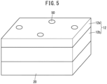
- FIG. 5 shows an example in which four pressure detection ports 50 are arranged near the centers of four sides of the upper surface of the body 12.
- FIG. 5 shows an example in which four pressure detection ports 50 are arranged near the centers of four sides of the upper surface of the body 12.
- the suction pad 10 includes flow passage adjustment valves 26 that adjust the flow passage areas of the communication passages 18 in accordance with the suction state of the workpiece W. Therefore, the vacuum pressure generated in the negative pressure chamber 16 can be caused to act, without being decreased, on an upper surface of the workpiece W that is in contact with the cavity (cavities) 22. In addition, since the pressure detection ports 50 for detecting the pressure in one or more cavities 22 of the sponge member 20 are provided, it is possible to easily confirm whether or not the workpiece W is being sucked.
- the detection passages 48 each vertically pass through the negative pressure chamber 16 and extend from the upper surface to the lower surface of the body 12, but the configuration of each detection passage is not limited thereto as long as the detection passage communicates with the cavity 22.
- the detection passage may be branched from the communication passage 18 at a position lower than the flow passage adjustment valve 26 and opened to a side surface of the body 12 without passing through the negative pressure chamber 16.
- the flow passage adjustment valves 26 are disposed in all of the communication passages 18, but the flow passage adjustment valve 26 may not be disposed in some of the communication passages 18.
- the flow passage adjustment valve 26 may not be disposed in the communication passage 18 corresponding to the cavity 22 having a high probability of being closed by the workpiece W regardless of the size of the workpiece W.
- the detection passage 48 including the pressure detection port 50 may be disposed corresponding to only one cavity 22 for which the flow passage adjustment valve 26 is not disposed.
- a suction pad 60 according to a second embodiment of the present invention will be described with reference to FIG. 6 .
- Constituent elements that are the same as or equivalent to those of the suction pad 10 according to the first embodiment are denoted by the same reference numerals, and detailed description thereof is omitted.
- the detection passage 48 of the body 12 is arranged for each of a plurality of selected cavities 22.
- the upper end of each detection passage 48 forms the pressure detection port 50.
- the respective pressure detection ports 50 are connected to a common flow path 64 via check valves 62, and a single pressure sensor 66 is connected to the common flow path 64. That is, the common pressure sensor 66 is connected to the plurality of pressure detection ports 50 via the check valves 62.
Landscapes
- Engineering & Computer Science (AREA)
- Mechanical Engineering (AREA)
- Robotics (AREA)
- Chemical & Material Sciences (AREA)
- Dispersion Chemistry (AREA)
- Human Computer Interaction (AREA)
- Manipulator (AREA)
Abstract
Description
- The present invention relates to a suction pad for sucking a workpiece using vacuum pressure, and more particularly to a suction pad capable of confirming the suction state of the workpiece.
- Conventionally, there is known a suction pad that sucks a workpiece by bringing a sponge member made of a porous material into contact with the workpiece and generating vacuum pressure inside the sponge member. There is also known a technique for detecting the suction state of a workpiece by detecting pressure in a path through which vacuum pressure is introduced into a suction pad.
- For example,
JP 2022-017935 A - In a vacuum suction device that includes a plurality of suction portions (suction pads) and is capable of sucking workpieces of various sizes, check valves (flow passage adjustment valves) may be disposed in respective paths that branch from a vacuum generator and reach the suction portions. By the action of the check valves, the vacuum pressure required for sucking the workpiece acts on the workpiece effectively. Also in a case where a large sponge pad including a large number of suction holes is used to suck workpieces of various sizes, it is desirable to dispose check valves as well.
- However, in the vacuum suction device in which the check valves are disposed, the suction state of the workpiece cannot be easily confirmed by simply disposing the pressure sensor. This is because, since the vacuum pressure is maintained by the action of the check valves regardless of whether the workpiece is being sucked or is not being sucked, there is no difference between the pressures detected by the pressure sensor, and the state where the workpiece is being sucked and the state where the workpiece is not being sucked cannot be distinguished from each other.
- The present invention has the object of solving the aforementioned problem.
- The present invention provides a suction pad comprising: a body; and a sponge member, wherein the body includes a negative pressure chamber, and a plurality of communication passages configured to communicate with the negative pressure chamber, and the sponge member includes a plurality of cavities configured to open toward a workpiece and communicate with the negative pressure chamber through the communication passages. A flow passage adjustment valve configured to adjust a flow passage area is disposed in each of the communication passages, and when vacuum pressure is generated in the negative pressure chamber and a cavity among the plurality of cavities is not closed by the workpiece, a flow passage area of a communication passage among the communication passages that corresponds to the cavity that is not closed by the workpiece is adjusted to be decreased. The suction pad further comprises a pressure detection port configured to detect pressure in at least one cavity among the plurality of cavities.
- The suction pad according to the present invention has a structure in which the flow passage adjustment valves are disposed in the communication passages connecting the cavities of the sponge member to the negative pressure chamber, and includes the pressure detection port for detecting the pressure in at least one cavity of the sponge member. Therefore, it is possible to easily confirm whether or not the workpiece is being sucked.
- The above and other objects, features, and advantages of the present invention will become more apparent from the following description when taken in conjunction with the accompanying drawings, in which a preferred embodiment of the present invention is shown by way of illustrative example.
-
-
FIG. 1 is a view schematically showing a cross section of a suction pad according to a first embodiment of the present invention; -
FIG. 2 is a view showing a specific structural example of a flow passage adjustment valve of the suction pad ofFIG. 1 ; -
FIG. 3 is a view schematically showing a cross section of the suction pad ofFIG. 1 when sucking a workpiece having a small size; -
FIG. 4 is a view schematically showing a cross section of the suction pad ofFIG. 1 when sucking a workpiece having a large size; -
FIG. 5 is a view showing an arrangement example of pressure detection ports in the suction pad ofFIG. 1 ; and -
FIG. 6 is a view schematically showing a cross section of a suction pad according to a second embodiment of the present invention. - A
suction pad 10 according to a first embodiment of the present invention will be described with reference toFIGS. 1 to 5 . As shown inFIG. 1 , thesuction pad 10 includes abody 12 and asponge member 20. In the following description, when terms in relation to upper and lower directions are used, such terms refer to the directions shown in the drawings, however, the actual arrangement of the respective constituent members is not limited thereby. - The
body 12 is formed of amain body 12a that has a box shape and opens downward, and aplate 12b that is thick and covers themain body 12a from below. Themain body 12a includes asuction port 14 connected to a vacuum generator (not shown). Thebody 12 includes therein anegative pressure chamber 16 communicating with thesuction port 14. Theplate 12b includes a plurality ofcommunication passages 18 communicating with thenegative pressure chamber 16. - The
sponge member 20 having a plate shape is attached to a lower surface of theplate 12b by means of bonding or the like. Thesponge member 20 includes a plurality ofcavities 22 opening toward a workpiece W. Thecavities 22 of thesponge member 20 communicate with thenegative pressure chamber 16 through thecommunication passages 18 of theplate 12b. Thesponge member 20 comes into contact with the workpiece W at a lower surface (bottom surface) 24 thereof. - The
sponge member 20 is made of a material having a semi-open and semi-closed cell structure, and is manufactured by foam-molding ethylene propylene rubber (EPDM), for example. Thesponge member 20 exhibits flexibility which is a property of open cells until it is compressed by a predetermined amount from a natural state, and exhibits airtightness which is a property of closed cells after it is compressed by the predetermined amount. - The
sponge member 20 can be deformed in accordance with the surface shape of the workpiece W by exhibiting flexibility. Even if the workpiece W has irregularities on its surface as in the case of a cardboard box in which beverage containers are packaged, no gap is generated between thesponge member 20 and the workpiece W. Thesponge member 20 comes into close contact with the workpiece W and then exhibits airtightness to cause vacuum pressure required for sucking the workpiece W to act on the workpiece W. - The thickness of the
sponge member 20 when no vertical compressive force is applied to thesponge member 20 is represented by T0, and the thickness of thesponge member 20 when a vertical compressive force is applied to thesponge member 20 is represented by T. Then, a compression amount (%) of thesponge member 20 is defined as (T0 - T)/T0 × 100. Although depending on the ratio of open cells and closed cells, thesponge member 20 exhibits sufficient airtightness when compressed to a compression amount of at least about 70 %, for example. - A flow
passage adjustment valve 26 is arranged in the middle of eachcommunication passage 18 of thebody 12. The flowpassage adjustment valve 26 adjusts the flow passage area of thecommunication passage 18 in accordance with the suction state of the workpiece W. When thecavity 22 is closed by the workpiece W, the flow passage area of thecommunication passage 18 is sufficiently increased, and the pressure in thecavity 22 becomes equal to the pressure in thenegative pressure chamber 16. That is, when thecavity 22 is closed by the workpiece W, the same vacuum pressure as the vacuum pressure generated in thenegative pressure chamber 16 is generated in thecavity 22. When thecavity 22 is not closed by the workpiece W, the flow passage area of thecommunication passage 18 is sufficiently decreased, and high vacuum pressure is generated in thenegative pressure chamber 16, while the pressure in thecavity 22 becomes substantially equal to the atmospheric pressure. - A specific structural example of the flow
passage adjustment valve 26 is shown inFIG. 2 . The flowpassage adjustment valve 26 includes a firstjoint member 28, a secondjoint member 32, and avalve element 36. Thetubular valve element 36 is disposed inside the tubularfirst joint member 28, and can be vertically displaced with respect to the firstjoint member 28. The firstjoint member 28 is provided with atapered seat portion 30 against which ahead part 38 of thevalve element 36 can abut. The tubular secondjoint member 32 is connected and fixed to the firstjoint member 28. Astopper 34 capable of abutting against a lower end of thevalve element 36 is attached to the secondjoint member 32. By thevalve element 36 abutting against thestopper 34, downward displacement of thevalve element 36 is regulated. - The
head part 38 of thevalve element 36 includes anorifice 40 at its center, and theorifice 40 communicates with aninner space 44 of thevalve element 36. A sidewall of thevalve element 36 includes a plurality ofopenings 42 that communicate with theinner space 44 of thevalve element 36. The area of the opening 42 is sufficiently larger than the area of theorifice 40. Theinner space 44 of thevalve element 36 communicates, at the lower end thereof, with an internal space of the secondjoint member 32. Aspring 46 for biasing thevalve element 36 downward is disposed between the firstjoint member 28 and thevalve element 36. - In a state where the
head part 38 of thevalve element 36 is separated from theseat portion 30 of the firstjoint member 28, an internal space of the firstjoint member 28 that is located above theseat portion 30 communicates with theinner space 44 of thevalve element 36 via theorifice 40 and the plurality ofopenings 42 of thevalve element 36. In a state where thehead part 38 of thevalve element 36 is in abutment against theseat portion 30 of the firstjoint member 28, the internal space of the firstjoint member 28 that is located above theseat portion 30 communicates with theinner space 44 of thevalve element 36 only via theorifice 40 of thevalve element 36. - When vacuum pressure is generated in the
negative pressure chamber 16 in a state where thecavity 22 is not closed by the workpiece W, air passes through theorifice 40 of thevalve element 36 from the lower side toward the upper side at a high flow velocity. Therefore, thevalve element 36 is displaced upward by the pressure difference generated before and after theorifice 40, and thehead part 38 of thevalve element 36 abuts against theseat portion 30 of the firstjoint member 28. When thehead part 38 of thevalve element 36 abuts against theseat portion 30, the flow passage area of thecommunication passage 18 decreases, and the flow velocity of the air passing through theorifice 40 further increases. As a result, the state where thehead part 38 of thevalve element 36 is in abutment against theseat portion 30 of the firstjoint member 28 is reliably maintained. - When the
cavity 22 is closed by the workpiece W, the flow rate of the air passing through theorifice 40 of thevalve element 36 decreases, and the flow velocity of the air passing through theorifice 40 decreases. Therefore, the pressure difference generated before and after theorifice 40 becomes small, thevalve element 36 is displaced downward by the biasing force of thespring 46, and thehead part 38 of thevalve element 36 moves away from theseat portion 30 of the firstjoint member 28. When thehead part 38 of thevalve element 36 moves away from theseat portion 30, the flow passage area of thecommunication passage 18 increases. - The
suction pad 10 can suck workpieces W of various sizes. The pressure in thenegative pressure chamber 16 of thebody 12 does not increase even if the workpiece W is small enough to contact only a part of thebottom surface 24 of thesponge member 20 and one or some of thecavities 22 of thesponge member 20 are open to the atmosphere. That is, even if there is acavity 22 which is not closed by the workpiece W, the vacuum pressure generated in thenegative pressure chamber 16 does not decrease due to the action of the flowpassage adjustment valve 26. - The
body 12 includes adetection passage 48 for detecting the pressure in apredetermined cavity 22 of thesponge member 20. Thedetection passage 48 is arranged for each of one or more selectedcavities 22. Thedetection passage 48 vertically passes through thenegative pressure chamber 16 and extends from an upper surface to a lower surface of thebody 12, and a lower end of thedetection passage 48 communicates with the correspondingcavity 22. An upper end of eachdetection passage 48 forms apressure detection port 50. Apressure sensor 52 is individually connected to eachpressure detection port 50. The pressure in the selectedcavity 22 is detected by thepressure sensor 52. - Among the plurality of
cavities 22, thecavity 22 for which thedetection passage 48 is correspondingly arranged is determined in consideration of the size of the workpiece W to be sucked. When the workpiece W of a predetermined size comes into contact with thesponge member 20, thedetection passages 48 are arranged corresponding to one ormore cavities 22 closed by the workpiece W, and one ormore cavities 22 that are not closed by the workpiece W. In order to explain the principle of the present invention using a simple drawing,FIG. 1 shows threecavities 22a to 22c. Thedetection passages 48 and thepressure sensors 52 are arranged corresponding to thecavity 22a and thecavity 22c among the three cavities. - Next, the operation of the
suction pad 10 according to the present embodiment for sucking the workpiece W will be described. Thesuction pad 10 is used by being attached to, for example, a conveying device (not shown). - When a command for sucking the workpiece W placed on a floor surface or the like and conveying the workpiece W to a predetermined place is issued from a host controller (not shown) such as a PLC, the conveying device is driven and the
suction pad 10 comes into contact with the workpiece W. At the same time or prior thereto, air in thenegative pressure chamber 16 is sucked from thesuction port 14 toward the vacuum generator. Although all thecavities 22 of thesponge member 20 are open to the atmosphere, the flow passage areas of thecommunication passages 18 are reduced by the flowpassage adjustment valves 26. Therefore, high vacuum pressure is easily generated in thenegative pressure chamber 16. - When a workpiece W1 having a small size comes into contact with a part of the
bottom surface 24 of thesponge member 20, one or some of thecavities 22 of thesponge member 20 are closed by the workpiece W1. Referring toFIG. 3 , thecavity 22a and thecavity 22b are closed by the workpiece W1, and thecavity 22c is not closed by the workpiece W1. Thecavities negative pressure chamber 16 through thecommunication passages 18 whose flow passage areas are sufficiently increased by the flowpassage adjustment valves 26. Therefore, the vacuum pressure generated in thenegative pressure chamber 16 is directly transmitted to thecavities cavities cavity 22c, which is not closed by the workpiece W1, communicates with thenegative pressure chamber 16 through thecommunication passage 18 whose flow passage area is reduced, the vacuum pressure generated in thenegative pressure chamber 16 does not decrease. - Due to the vacuum pressure generated in the
negative pressure chamber 16, an upward force (lifting force) acts on the workpiece W1. The lifting force is represented by ΔP·S, where ΔP represents a difference between the atmospheric pressure and the pressure in thenegative pressure chamber 16, and S is the total cross-sectional area of thecavities 22 closed by the workpiece W1. On the other hand, a downward force acting on the workpiece W1 is represented by (W + F), where W represents a weight of the workpiece W1 and F is a repulsive force caused by the compression of thesponge member 20. The repulsive force F changes according to the compression amount of thesponge member 20. When thesponge member 20 is compressed by a predetermined amount, ΔP·S = W + F is established. That is, the upward force and the downward force acting on the workpiece W1 are balanced, and the workpiece W1 is stably held by thesuction pad 10. - When a workpiece W2 having a large size comes into contact with the
entire bottom surface 24 of thesponge member 20, all thecavities 22 of thesponge member 20 are closed by the workpiece W2. Referring toFIG. 4 , thecavities 22a to 22c communicate with thenegative pressure chamber 16 through thecommunication passages 18 whose flow passage areas are sufficiently increased by the flowpassage adjustment valves 26, and the vacuum pressure acts on an upper surface portion of the workpiece W2 that is in contact with thecavities 22a to 22c. As in the case of the workpiece W1 having a small size, the upward force and the downward force acting on the workpiece W2 are balanced, whereby the workpiece W2 is stably held by thesuction pad 10. - Next, a method of confirming the suction state of the workpiece W using the
suction pad 10 according to the present embodiment will be described. - When the workpiece W1 having such a size that it contacts only a part of the
bottom surface 24 of thesponge member 20 is being sucked, the vacuum pressure is detected by at least one of thepressure sensors 52 and the atmospheric pressure is detected by the remainingpressure sensors 52. Referring toFIG. 3 , thepressure sensor 52 corresponding to thecavity 22a closed by the workpiece W1 indicates the vacuum pressure, and thepressure sensor 52 corresponding to thecavity 22c that is not closed by the workpiece W1 indicates the atmospheric pressure. On the other hand, when the workpiece W1 is not being sucked, the atmospheric pressure is detected by thesepressure sensors 52. Therefore, by monitoring the pressures detected by therespective pressure sensors 52, it is possible to determine whether or not the workpiece W1 is being sucked. - When the workpiece W2 having such a size that it contacts the
entire bottom surface 24 of thesponge member 20 is being sucked, the vacuum pressure is detected by all thepressure sensors 52. Referring toFIG. 4 , both thepressure sensors 52 corresponding to thecavity 22a and thecavity 22c closed by the workpiece W2 indicate the vacuum pressure. On the other hand, when the workpiece W2 is not being sucked, the atmospheric pressure is detected by thesepressure sensors 52. Therefore, by monitoring the pressures detected by therespective pressure sensors 52, it is possible to determine whether or not the workpiece W2 is being sucked. - If the plurality of
pressure detection ports 50 are arranged efficiently, the suction state of the workpiece W can be accurately confirmed.FIG. 5 shows an example in which fourpressure detection ports 50 are arranged near the centers of four sides of the upper surface of thebody 12. In particular, even if there is a variation in the position at which the workpiece W1 having a small size comes into contact with thebottom surface 24 of thesponge member 20, there is a high probability that at least one of the fourcavities 22 corresponding to these fourpressure detection ports 50 is closed by the workpiece W1. That is, even if the accuracy of the suction position of the workpiece W with respect to thesponge member 20 is low, it is possible to easily confirm whether or not the workpiece W is being sucked. - The
suction pad 10 according to the present embodiment includes flowpassage adjustment valves 26 that adjust the flow passage areas of thecommunication passages 18 in accordance with the suction state of the workpiece W. Therefore, the vacuum pressure generated in thenegative pressure chamber 16 can be caused to act, without being decreased, on an upper surface of the workpiece W that is in contact with the cavity (cavities) 22. In addition, since thepressure detection ports 50 for detecting the pressure in one ormore cavities 22 of thesponge member 20 are provided, it is possible to easily confirm whether or not the workpiece W is being sucked. - In the present embodiment, the
detection passages 48 each vertically pass through thenegative pressure chamber 16 and extend from the upper surface to the lower surface of thebody 12, but the configuration of each detection passage is not limited thereto as long as the detection passage communicates with thecavity 22. For example, the detection passage may be branched from thecommunication passage 18 at a position lower than the flowpassage adjustment valve 26 and opened to a side surface of thebody 12 without passing through thenegative pressure chamber 16. - Further, in the present embodiment, the flow
passage adjustment valves 26 are disposed in all of thecommunication passages 18, but the flowpassage adjustment valve 26 may not be disposed in some of thecommunication passages 18. For example, the flowpassage adjustment valve 26 may not be disposed in thecommunication passage 18 corresponding to thecavity 22 having a high probability of being closed by the workpiece W regardless of the size of the workpiece W. In this case, thedetection passage 48 including thepressure detection port 50 may be disposed corresponding to only onecavity 22 for which the flowpassage adjustment valve 26 is not disposed. - A
suction pad 60 according to a second embodiment of the present invention will be described with reference toFIG. 6 . Constituent elements that are the same as or equivalent to those of thesuction pad 10 according to the first embodiment are denoted by the same reference numerals, and detailed description thereof is omitted. - The
detection passage 48 of thebody 12 is arranged for each of a plurality of selectedcavities 22. The upper end of eachdetection passage 48 forms thepressure detection port 50. The respectivepressure detection ports 50 are connected to acommon flow path 64 viacheck valves 62, and asingle pressure sensor 66 is connected to thecommon flow path 64. That is, thecommon pressure sensor 66 is connected to the plurality ofpressure detection ports 50 via thecheck valves 62. - When at least one
cavity 22 among the plurality of selectedcavities 22 is closed by the workpiece W, vacuum pressure is generated in thiscavity 22, and the vacuum pressure is detected by thepressure sensor 66. On the other hand, when the plurality of selectedcavities 22 are not closed by the workpiece W, the pressure detected by thepressure sensor 66 remains the atmospheric pressure. Therefore, by monitoring the pressure detected by thepressure sensor 66, it is possible to determine whether or not the workpiece W is being sucked.
Claims (6)
- A suction pad (10, 60) comprising: a body (12); and a sponge member (20),wherein the body includes a negative pressure chamber (16), and a plurality of communication passages (18) configured to communicate with the negative pressure chamber, and the sponge member includes a plurality of cavities (22) configured to open toward a workpiece and communicate with the negative pressure chamber through the communication passages,a flow passage adjustment valve (26) configured to adjust a flow passage area is disposed in each of the communication passages, and when vacuum pressure is generated in the negative pressure chamber and a cavity among the plurality of cavities is not closed by the workpiece, a flow passage area of a communication passage among the communication passages that corresponds to the cavity that is not closed by the workpiece is adjusted to be decreased, andthe suction pad further comprises a pressure detection port (50) configured to detect pressure in at least one cavity among the plurality of cavities.
- The suction pad according to claim 1, wherein
the body includes a detection passage (48) configured to communicate with a corresponding one of the cavities of the sponge member. - The suction pad according to claim 2, wherein
the detection passage vertically passes through the body, and an end of the detection passage forms the pressure detection port. - The suction pad according to claim 3, wherein
the pressure detection port is disposed near a center of each of four sides of an upper surface of the body. - The suction pad according to claim 1, wherein
the pressure detection port is provided in plurality, and a pressure sensor (52) is individually connected to each of the plurality of pressure detection ports. - The suction pad according to claim 1, wherein
the pressure detection port is provided in plurality, and a common pressure sensor (66) is connected to the plurality of pressure detection ports via check valves (62).
Applications Claiming Priority (1)
| Application Number | Priority Date | Filing Date | Title |
|---|---|---|---|
| JP2022197654A JP2024083701A (en) | 2022-12-12 | 2022-12-12 | Suction pad |
Publications (2)
| Publication Number | Publication Date |
|---|---|
| EP4385681A1 true EP4385681A1 (en) | 2024-06-19 |
| EP4385681B1 EP4385681B1 (en) | 2025-06-18 |
Family
ID=89121424
Family Applications (1)
| Application Number | Title | Priority Date | Filing Date |
|---|---|---|---|
| EP23214510.2A Active EP4385681B1 (en) | 2022-12-12 | 2023-12-06 | Suction pad |
Country Status (5)
| Country | Link |
|---|---|
| US (1) | US20240189965A1 (en) |
| EP (1) | EP4385681B1 (en) |
| JP (1) | JP2024083701A (en) |
| KR (1) | KR20240087603A (en) |
| CN (1) | CN118181172A (en) |
Citations (11)
| Publication number | Priority date | Publication date | Assignee | Title |
|---|---|---|---|---|
| JPH09183089A (en) * | 1996-01-05 | 1997-07-15 | Ehime Pref Gov | Search type vacuum suction device and air control valve for vacuum suction |
| JP2001341089A (en) * | 2000-06-01 | 2001-12-11 | Yasuo Yamanaka | Article sucking device and its method |
| JP2007331056A (en) * | 2006-06-14 | 2007-12-27 | Sharp Corp | Vacuum suction device and suction force estimation method |
| JP2008238312A (en) * | 2007-03-27 | 2008-10-09 | Yasuo Yamanaka | Article suction device |
| US20170073174A1 (en) * | 2015-09-15 | 2017-03-16 | Kabushiki Kaisha Toshiba | Vacuum device and article holding device |
| US20190248025A1 (en) * | 2015-08-26 | 2019-08-15 | Berkshire Grey, Inc. | Systems and methods for providing vacuum valve assemblies for end effectors |
| US20200103463A1 (en) * | 2018-09-27 | 2020-04-02 | Seiko Epson Corporation | Electronic Component Handler And Electronic Component Tester |
| US20210053192A1 (en) * | 2019-08-19 | 2021-02-25 | Zhejiang University | Suction device |
| US20210053216A1 (en) * | 2019-08-21 | 2021-02-25 | Mujin, Inc. | Robotic multi-gripper assemblies and methods for gripping and holding objects |
| US20210331331A1 (en) * | 2020-04-28 | 2021-10-28 | Joulin Cemma | Suction gripper head with a foam body |
| JP2022017935A (en) | 2020-07-14 | 2022-01-26 | ヤンマーホールディングス株式会社 | Adsorption pad and harvesting adsorption hand |
Family Cites Families (1)
| Publication number | Priority date | Publication date | Assignee | Title |
|---|---|---|---|---|
| CN103072822B (en) * | 2012-09-05 | 2015-06-03 | 王伟光 | Multi-adaptive sponge sucker system and method for adsorbing workpieces through same |
-
2022
- 2022-12-12 JP JP2022197654A patent/JP2024083701A/en active Pending
-
2023
- 2023-12-06 EP EP23214510.2A patent/EP4385681B1/en active Active
- 2023-12-07 US US18/531,959 patent/US20240189965A1/en active Pending
- 2023-12-11 CN CN202311691357.4A patent/CN118181172A/en active Pending
- 2023-12-11 KR KR1020230178518A patent/KR20240087603A/en active Pending
Patent Citations (11)
| Publication number | Priority date | Publication date | Assignee | Title |
|---|---|---|---|---|
| JPH09183089A (en) * | 1996-01-05 | 1997-07-15 | Ehime Pref Gov | Search type vacuum suction device and air control valve for vacuum suction |
| JP2001341089A (en) * | 2000-06-01 | 2001-12-11 | Yasuo Yamanaka | Article sucking device and its method |
| JP2007331056A (en) * | 2006-06-14 | 2007-12-27 | Sharp Corp | Vacuum suction device and suction force estimation method |
| JP2008238312A (en) * | 2007-03-27 | 2008-10-09 | Yasuo Yamanaka | Article suction device |
| US20190248025A1 (en) * | 2015-08-26 | 2019-08-15 | Berkshire Grey, Inc. | Systems and methods for providing vacuum valve assemblies for end effectors |
| US20170073174A1 (en) * | 2015-09-15 | 2017-03-16 | Kabushiki Kaisha Toshiba | Vacuum device and article holding device |
| US20200103463A1 (en) * | 2018-09-27 | 2020-04-02 | Seiko Epson Corporation | Electronic Component Handler And Electronic Component Tester |
| US20210053192A1 (en) * | 2019-08-19 | 2021-02-25 | Zhejiang University | Suction device |
| US20210053216A1 (en) * | 2019-08-21 | 2021-02-25 | Mujin, Inc. | Robotic multi-gripper assemblies and methods for gripping and holding objects |
| US20210331331A1 (en) * | 2020-04-28 | 2021-10-28 | Joulin Cemma | Suction gripper head with a foam body |
| JP2022017935A (en) | 2020-07-14 | 2022-01-26 | ヤンマーホールディングス株式会社 | Adsorption pad and harvesting adsorption hand |
Also Published As
| Publication number | Publication date |
|---|---|
| EP4385681B1 (en) | 2025-06-18 |
| CN118181172A (en) | 2024-06-14 |
| JP2024083701A (en) | 2024-06-24 |
| KR20240087603A (en) | 2024-06-19 |
| US20240189965A1 (en) | 2024-06-13 |
Similar Documents
| Publication | Publication Date | Title |
|---|---|---|
| US20230249362A1 (en) | Systems and methods for providing vacuum valve assemblies for end effectors | |
| CN106466806B (en) | Substrate suction method, polishing apparatus, substrate holding apparatus, substrate suction determination method, and pressure control method | |
| US7938466B2 (en) | Suction gripper device | |
| WO2000006352A1 (en) | Apparatus for sensing the presence of a wafer | |
| KR20180048167A (en) | Picker assembly and apparatus for picking semiconductor chips using the same | |
| WO2008134339A4 (en) | Auto-release venturi with vacuum switch | |
| CN105824327A (en) | Pneumatic Control and Measuring Device as well as Seat Comfort System | |
| JP2020161585A (en) | Work transfer hand | |
| US20240189965A1 (en) | Suction pad | |
| KR20200051815A (en) | Adsorption stage | |
| TW202112511A (en) | Picker and hand including the same | |
| CN117047813A (en) | Feeding and discharging manipulator | |
| EP4385683A1 (en) | Suction pad | |
| CN110509179A (en) | The manufacturing method of base plate keeping device, substrate grinding device, elastic component and base plate keeping device | |
| KR20220058354A (en) | Semiconductor manufacturing apparatus and chip handling method | |
| CN223712714U (en) | Cylinder pressing device and wafer bonding chuck assembly | |
| JP2006275595A (en) | Ic conveyor and contactor | |
| JP2000079589A (en) | Suction pad and suction hand using the suction pad | |
| JP3118580B2 (en) | Pinhole inspection device for sealed packaging | |
| JPH11291188A (en) | Vibratory suction cylinder | |
| JPH0535941Y2 (en) | ||
| RU2304505C2 (en) | Vacuum clamping head | |
| JP2505684Y2 (en) | Vacuum transfer device for thin plate | |
| KR20230047950A (en) | Separation device and separation method | |
| JPH113898A (en) | Supply mechanism of semiconductor manufacturing equipment |
Legal Events
| Date | Code | Title | Description |
|---|---|---|---|
| PUAI | Public reference made under article 153(3) epc to a published international application that has entered the european phase |
Free format text: ORIGINAL CODE: 0009012 |
|
| STAA | Information on the status of an ep patent application or granted ep patent |
Free format text: STATUS: THE APPLICATION HAS BEEN PUBLISHED |
|
| AK | Designated contracting states |
Kind code of ref document: A1 Designated state(s): AL AT BE BG CH CY CZ DE DK EE ES FI FR GB GR HR HU IE IS IT LI LT LU LV MC ME MK MT NL NO PL PT RO RS SE SI SK SM TR |
|
| STAA | Information on the status of an ep patent application or granted ep patent |
Free format text: STATUS: REQUEST FOR EXAMINATION WAS MADE |
|
| 17P | Request for examination filed |
Effective date: 20241115 |
|
| RBV | Designated contracting states (corrected) |
Designated state(s): AL AT BE BG CH CY CZ DE DK EE ES FI FR GB GR HR HU IE IS IT LI LT LU LV MC ME MK MT NL NO PL PT RO RS SE SI SK SM TR |
|
| GRAP | Despatch of communication of intention to grant a patent |
Free format text: ORIGINAL CODE: EPIDOSNIGR1 |
|
| STAA | Information on the status of an ep patent application or granted ep patent |
Free format text: STATUS: GRANT OF PATENT IS INTENDED |
|
| INTG | Intention to grant announced |
Effective date: 20250217 |
|
| GRAS | Grant fee paid |
Free format text: ORIGINAL CODE: EPIDOSNIGR3 |
|
| GRAA | (expected) grant |
Free format text: ORIGINAL CODE: 0009210 |
|
| STAA | Information on the status of an ep patent application or granted ep patent |
Free format text: STATUS: THE PATENT HAS BEEN GRANTED |
|
| RAP3 | Party data changed (applicant data changed or rights of an application transferred) |
Owner name: SMC CORPORATION |
|
| AK | Designated contracting states |
Kind code of ref document: B1 Designated state(s): AL AT BE BG CH CY CZ DE DK EE ES FI FR GB GR HR HU IE IS IT LI LT LU LV MC ME MK MT NL NO PL PT RO RS SE SI SK SM TR |
|
| REG | Reference to a national code |
Ref country code: GB Ref legal event code: FG4D |
|
| REG | Reference to a national code |
Ref country code: CH Ref legal event code: EP |
|
| REG | Reference to a national code |
Ref country code: DE Ref legal event code: R096 Ref document number: 602023004107 Country of ref document: DE |
|
| REG | Reference to a national code |
Ref country code: CH Ref legal event code: EP |
|
| REG | Reference to a national code |
Ref country code: IE Ref legal event code: FG4D |
|
| PG25 | Lapsed in a contracting state [announced via postgrant information from national office to epo] |
Ref country code: FI Free format text: LAPSE BECAUSE OF FAILURE TO SUBMIT A TRANSLATION OF THE DESCRIPTION OR TO PAY THE FEE WITHIN THE PRESCRIBED TIME-LIMIT Effective date: 20250618 |
|
| REG | Reference to a national code |
Ref country code: LT Ref legal event code: MG9D |
|
| PG25 | Lapsed in a contracting state [announced via postgrant information from national office to epo] |
Ref country code: GR Free format text: LAPSE BECAUSE OF FAILURE TO SUBMIT A TRANSLATION OF THE DESCRIPTION OR TO PAY THE FEE WITHIN THE PRESCRIBED TIME-LIMIT Effective date: 20250919 Ref country code: NO Free format text: LAPSE BECAUSE OF FAILURE TO SUBMIT A TRANSLATION OF THE DESCRIPTION OR TO PAY THE FEE WITHIN THE PRESCRIBED TIME-LIMIT Effective date: 20250918 |
|
| PG25 | Lapsed in a contracting state [announced via postgrant information from national office to epo] |
Ref country code: BG Free format text: LAPSE BECAUSE OF FAILURE TO SUBMIT A TRANSLATION OF THE DESCRIPTION OR TO PAY THE FEE WITHIN THE PRESCRIBED TIME-LIMIT Effective date: 20250618 |
|
| PG25 | Lapsed in a contracting state [announced via postgrant information from national office to epo] |
Ref country code: HR Free format text: LAPSE BECAUSE OF FAILURE TO SUBMIT A TRANSLATION OF THE DESCRIPTION OR TO PAY THE FEE WITHIN THE PRESCRIBED TIME-LIMIT Effective date: 20250618 |
|
| PG25 | Lapsed in a contracting state [announced via postgrant information from national office to epo] |
Ref country code: RS Free format text: LAPSE BECAUSE OF FAILURE TO SUBMIT A TRANSLATION OF THE DESCRIPTION OR TO PAY THE FEE WITHIN THE PRESCRIBED TIME-LIMIT Effective date: 20250918 |
|
| REG | Reference to a national code |
Ref country code: NL Ref legal event code: MP Effective date: 20250618 |
|
| PG25 | Lapsed in a contracting state [announced via postgrant information from national office to epo] |
Ref country code: LV Free format text: LAPSE BECAUSE OF FAILURE TO SUBMIT A TRANSLATION OF THE DESCRIPTION OR TO PAY THE FEE WITHIN THE PRESCRIBED TIME-LIMIT Effective date: 20250618 |
|
| PG25 | Lapsed in a contracting state [announced via postgrant information from national office to epo] |
Ref country code: NL Free format text: LAPSE BECAUSE OF FAILURE TO SUBMIT A TRANSLATION OF THE DESCRIPTION OR TO PAY THE FEE WITHIN THE PRESCRIBED TIME-LIMIT Effective date: 20250618 |
|
| PG25 | Lapsed in a contracting state [announced via postgrant information from national office to epo] |
Ref country code: PT Free format text: LAPSE BECAUSE OF FAILURE TO SUBMIT A TRANSLATION OF THE DESCRIPTION OR TO PAY THE FEE WITHIN THE PRESCRIBED TIME-LIMIT Effective date: 20251020 |
|
| REG | Reference to a national code |
Ref country code: AT Ref legal event code: MK05 Ref document number: 1803807 Country of ref document: AT Kind code of ref document: T Effective date: 20250618 |
|
| PG25 | Lapsed in a contracting state [announced via postgrant information from national office to epo] |
Ref country code: IS Free format text: LAPSE BECAUSE OF FAILURE TO SUBMIT A TRANSLATION OF THE DESCRIPTION OR TO PAY THE FEE WITHIN THE PRESCRIBED TIME-LIMIT Effective date: 20251018 |
|
| PG25 | Lapsed in a contracting state [announced via postgrant information from national office to epo] |
Ref country code: AT Free format text: LAPSE BECAUSE OF FAILURE TO SUBMIT A TRANSLATION OF THE DESCRIPTION OR TO PAY THE FEE WITHIN THE PRESCRIBED TIME-LIMIT Effective date: 20250618 Ref country code: SM Free format text: LAPSE BECAUSE OF FAILURE TO SUBMIT A TRANSLATION OF THE DESCRIPTION OR TO PAY THE FEE WITHIN THE PRESCRIBED TIME-LIMIT Effective date: 20250618 |
|
| PG25 | Lapsed in a contracting state [announced via postgrant information from national office to epo] |
Ref country code: CZ Free format text: LAPSE BECAUSE OF FAILURE TO SUBMIT A TRANSLATION OF THE DESCRIPTION OR TO PAY THE FEE WITHIN THE PRESCRIBED TIME-LIMIT Effective date: 20250618 |
|
| PG25 | Lapsed in a contracting state [announced via postgrant information from national office to epo] |
Ref country code: PL Free format text: LAPSE BECAUSE OF FAILURE TO SUBMIT A TRANSLATION OF THE DESCRIPTION OR TO PAY THE FEE WITHIN THE PRESCRIBED TIME-LIMIT Effective date: 20250618 |
|
| PG25 | Lapsed in a contracting state [announced via postgrant information from national office to epo] |
Ref country code: EE Free format text: LAPSE BECAUSE OF FAILURE TO SUBMIT A TRANSLATION OF THE DESCRIPTION OR TO PAY THE FEE WITHIN THE PRESCRIBED TIME-LIMIT Effective date: 20250618 |
|
| PG25 | Lapsed in a contracting state [announced via postgrant information from national office to epo] |
Ref country code: SK Free format text: LAPSE BECAUSE OF FAILURE TO SUBMIT A TRANSLATION OF THE DESCRIPTION OR TO PAY THE FEE WITHIN THE PRESCRIBED TIME-LIMIT Effective date: 20250618 |
|
| PG25 | Lapsed in a contracting state [announced via postgrant information from national office to epo] |
Ref country code: ES Free format text: LAPSE BECAUSE OF FAILURE TO SUBMIT A TRANSLATION OF THE DESCRIPTION OR TO PAY THE FEE WITHIN THE PRESCRIBED TIME-LIMIT Effective date: 20250618 |
|
| PG25 | Lapsed in a contracting state [announced via postgrant information from national office to epo] |
Ref country code: RO Free format text: LAPSE BECAUSE OF FAILURE TO SUBMIT A TRANSLATION OF THE DESCRIPTION OR TO PAY THE FEE WITHIN THE PRESCRIBED TIME-LIMIT Effective date: 20250618 |
|
| REG | Reference to a national code |
Ref country code: DE Ref legal event code: R097 Ref document number: 602023004107 Country of ref document: DE |
|
| PG25 | Lapsed in a contracting state [announced via postgrant information from national office to epo] |
Ref country code: DK Free format text: LAPSE BECAUSE OF FAILURE TO SUBMIT A TRANSLATION OF THE DESCRIPTION OR TO PAY THE FEE WITHIN THE PRESCRIBED TIME-LIMIT Effective date: 20250618 |
|
| PGFP | Annual fee paid to national office [announced via postgrant information from national office to epo] |
Ref country code: DE Payment date: 20251218 Year of fee payment: 3 |
|
| PG25 | Lapsed in a contracting state [announced via postgrant information from national office to epo] |
Ref country code: IT Free format text: LAPSE BECAUSE OF FAILURE TO SUBMIT A TRANSLATION OF THE DESCRIPTION OR TO PAY THE FEE WITHIN THE PRESCRIBED TIME-LIMIT Effective date: 20250618 |
|
| PLBE | No opposition filed within time limit |
Free format text: ORIGINAL CODE: 0009261 |
|
| STAA | Information on the status of an ep patent application or granted ep patent |
Free format text: STATUS: NO OPPOSITION FILED WITHIN TIME LIMIT |
|
| REG | Reference to a national code |
Ref country code: CH Ref legal event code: L10 Free format text: ST27 STATUS EVENT CODE: U-0-0-L10-L00 (AS PROVIDED BY THE NATIONAL OFFICE) Effective date: 20260430 |