EP4385484B1 - Aufblasbares massagebecken - Google Patents
Aufblasbares massagebecken Download PDFInfo
- Publication number
- EP4385484B1 EP4385484B1 EP23199386.6A EP23199386A EP4385484B1 EP 4385484 B1 EP4385484 B1 EP 4385484B1 EP 23199386 A EP23199386 A EP 23199386A EP 4385484 B1 EP4385484 B1 EP 4385484B1
- Authority
- EP
- European Patent Office
- Prior art keywords
- wall
- pool
- control box
- connector
- inflation
- Prior art date
- Legal status (The legal status is an assumption and is not a legal conclusion. Google has not performed a legal analysis and makes no representation as to the accuracy of the status listed.)
- Active
Links
Images


Classifications
-
- A—HUMAN NECESSITIES
- A61—MEDICAL OR VETERINARY SCIENCE; HYGIENE
- A61H—PHYSICAL THERAPY APPARATUS, e.g. DEVICES FOR LOCATING OR STIMULATING REFLEX POINTS IN THE BODY; ARTIFICIAL RESPIRATION; MASSAGE; BATHING DEVICES FOR SPECIAL THERAPEUTIC OR HYGIENIC PURPOSES OR SPECIFIC PARTS OF THE BODY
- A61H33/00—Bathing devices for special therapeutic or hygienic purposes
- A61H33/02—Bathing devices for use with gas-containing liquid, or liquid in which gas is led or generated, e.g. carbon dioxide baths
-
- A—HUMAN NECESSITIES
- A61—MEDICAL OR VETERINARY SCIENCE; HYGIENE
- A61H—PHYSICAL THERAPY APPARATUS, e.g. DEVICES FOR LOCATING OR STIMULATING REFLEX POINTS IN THE BODY; ARTIFICIAL RESPIRATION; MASSAGE; BATHING DEVICES FOR SPECIAL THERAPEUTIC OR HYGIENIC PURPOSES OR SPECIFIC PARTS OF THE BODY
- A61H33/00—Bathing devices for special therapeutic or hygienic purposes
- A61H33/0087—Therapeutic baths with agitated or circulated water
-
- A—HUMAN NECESSITIES
- A61—MEDICAL OR VETERINARY SCIENCE; HYGIENE
- A61H—PHYSICAL THERAPY APPARATUS, e.g. DEVICES FOR LOCATING OR STIMULATING REFLEX POINTS IN THE BODY; ARTIFICIAL RESPIRATION; MASSAGE; BATHING DEVICES FOR SPECIAL THERAPEUTIC OR HYGIENIC PURPOSES OR SPECIFIC PARTS OF THE BODY
- A61H33/00—Bathing devices for special therapeutic or hygienic purposes
- A61H33/02—Bathing devices for use with gas-containing liquid, or liquid in which gas is led or generated, e.g. carbon dioxide baths
- A61H33/028—Means for producing a flow of gas, e.g. blowers, compressors
-
- E—FIXED CONSTRUCTIONS
- E04—BUILDING
- E04H—BUILDINGS OR LIKE STRUCTURES FOR PARTICULAR PURPOSES; SWIMMING OR SPLASH BATHS OR POOLS; MASTS; FENCING; TENTS OR CANOPIES, IN GENERAL
- E04H4/00—Swimming or splash baths or pools
- E04H4/0018—Easily movable or transportable swimming pools
- E04H4/0025—Easily movable or transportable swimming pools with inflatable parts
-
- A—HUMAN NECESSITIES
- A61—MEDICAL OR VETERINARY SCIENCE; HYGIENE
- A61H—PHYSICAL THERAPY APPARATUS, e.g. DEVICES FOR LOCATING OR STIMULATING REFLEX POINTS IN THE BODY; ARTIFICIAL RESPIRATION; MASSAGE; BATHING DEVICES FOR SPECIAL THERAPEUTIC OR HYGIENIC PURPOSES OR SPECIFIC PARTS OF THE BODY
- A61H2201/00—Characteristics of apparatus not provided for in the preceding codes
- A61H2201/01—Constructive details
- A61H2201/0103—Constructive details inflatable
-
- A—HUMAN NECESSITIES
- A61—MEDICAL OR VETERINARY SCIENCE; HYGIENE
- A61H—PHYSICAL THERAPY APPARATUS, e.g. DEVICES FOR LOCATING OR STIMULATING REFLEX POINTS IN THE BODY; ARTIFICIAL RESPIRATION; MASSAGE; BATHING DEVICES FOR SPECIAL THERAPEUTIC OR HYGIENIC PURPOSES OR SPECIFIC PARTS OF THE BODY
- A61H2201/00—Characteristics of apparatus not provided for in the preceding codes
- A61H2201/02—Characteristics of apparatus not provided for in the preceding codes heated or cooled
- A61H2201/0207—Characteristics of apparatus not provided for in the preceding codes heated or cooled heated
-
- A—HUMAN NECESSITIES
- A61—MEDICAL OR VETERINARY SCIENCE; HYGIENE
- A61H—PHYSICAL THERAPY APPARATUS, e.g. DEVICES FOR LOCATING OR STIMULATING REFLEX POINTS IN THE BODY; ARTIFICIAL RESPIRATION; MASSAGE; BATHING DEVICES FOR SPECIAL THERAPEUTIC OR HYGIENIC PURPOSES OR SPECIFIC PARTS OF THE BODY
- A61H33/00—Bathing devices for special therapeutic or hygienic purposes
- A61H33/0095—Arrangements for varying the temperature of the liquid
-
- A—HUMAN NECESSITIES
- A61—MEDICAL OR VETERINARY SCIENCE; HYGIENE
- A61H—PHYSICAL THERAPY APPARATUS, e.g. DEVICES FOR LOCATING OR STIMULATING REFLEX POINTS IN THE BODY; ARTIFICIAL RESPIRATION; MASSAGE; BATHING DEVICES FOR SPECIAL THERAPEUTIC OR HYGIENIC PURPOSES OR SPECIFIC PARTS OF THE BODY
- A61H33/00—Bathing devices for special therapeutic or hygienic purposes
- A61H33/60—Components specifically designed for the therapeutic baths of groups A61H33/00
- A61H33/6005—Special constructive structural details of the bathtub, e.g. of the walls or supporting structure
Definitions
- the present disclosure generally relates to the technical field of above-ground pools, and in particular to an inflatable massage pool.
- a portable massage (SPA) pool is a standalone pool holding warm or hot water in which one or more people are partially immersed.
- a massage pool product of the existing design comprises an inflatable SPA pool having a massage function, which has an inflatable pool body, with an inner wall or a bottom portion of the body being provided with a massage nozzle that can spray air or water to achieve a local massage function.
- An existing inflatable massage pool in the market generally has a control box placed next to the pool.
- the control box is generally equipped with a water pump, a heater, an air pump, etc., so as to achieve functions of filtering, heating and massage.
- Such a control box is usually placed outside a pool body of the massage pool. More specifically, the massage control box and the pool body are arranged separately, occupying a large area during use.
- the existing inflatable massage is complicated for installation and inconvenient for operation for a user.
- the purpose of the present disclosure is to propose an improved inflatable massage pool, in which at least one of the drawbacks in the conventional inflatable massage pool is overcome..
- An inflatable massage pool according to the present invention is defined by independent claim 1 as appended. Further preferable embodiments are given in the dependent claims.
- One or more of the pool body, the air passage and the air inlet bag are made of a weldable material such as a PVC material or a PVC composite material
- the pool wall can be connected to the pool bottom by means of hot-melt welding, etc. to form the pool body, and the air passage can be formed at the pool bottom, preferably near or at the corner between the pool bottom 203 and the inner wall 200.
- FIGS. 7 to 9 show the fittings of the water outlet end (water outlet connection) and the water inlet end (water inlet connection) of the control box 4.
- the water inlet assembly (pool water inlet connector ) 11 and the water outlet assembly (pool water outlet connector) 9 are connected to the water inlet end 10 and the water outlet end 8 of the control box 4, respectively, by means of the water inlet intermediate member (axial sealing assembly) 100 and the water outlet intermediate member (first axial sealing assembly) 800.
- the water inlet intermediate member 100 and the water outlet intermediate member 800 may be welded or adhered to the inner wall 200 of the pool body.
- control box is disposed in the pool body to form an integrated structure, so that the product is aesthetically pleasing in overall appearance, occupies small space, and is convenient for the user to operate; and the control box is separated from the air chamber of the pool body in a sealing manner, achieving safe and reliable use.
- FIGS. 10-37 other embodiments according to the present invention are described. For the sake of completeness in disclosure, some features already discussed above may again be described.
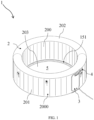
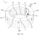
- the inflatable massage pool 1 includes: a pool body 2, a control box accommodating cavity (accommodating chamber) 3, and a control box 4, where the pool body 2 includes a pool wall 2000, and the pool wall 2000 defines an inflatable chamber (air chamber).
- the pool wall 2000 includes an inner wall 200, an outer wall 201, a top wall 202 and a pool wall 203 (or a part of the pool bottom 203).
- the inner wall 200, the outer wall 201, the top wall 202 and the pool bottom 203 (or a part of the pool bottom 203) define the inflatable chamber described above.
- the inflatable chamber is formed by welding an upper end 200a of the inner wall 200 to the top wall 202 and welding a lower end 200b of the inner wall 200 to at least a part of the pool bottom 203; and by welding an upper end 201a of the outer wall 201 to the top wall 202 and welding a lower end 201b of the outer wall 201 to the pool bottom 203.
- the inner wall 200, the outer wall 201, the top wall 202 and the pool bottom 203 are partially or completely made of a weldable material.
- the weldable material includes thermoplastic urethane (TPU) or polyvinyl chloride (PVC).
- the pool wall 2000 and the pool bottom 203 define a water placement zone (water receptacle) 5.
- the control box accommodating cavity 3 is provided in the pool wall 2000 and isolated from the inflatable chamber in a sealed manner.
- the control box 4 is located in the control box accommodating cavity 3.
- the control box 4 is configured to supply air and/or water to the pool body 2.
- the control box 4 is in fluid communication with the water placement zone 5 of the pool body 2.
- the control box 4 is configured to control various functions of the inflatable massage pool 1.
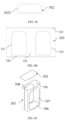
- the inflatable chamber is further internally provided with a tensioning member 6.
- the tensioning member 6 is connected to the inner wall 200 and the outer wall 201 of the pool body 2 separately. After being tensioned, the tensioning member 6 provides a pulling force so as to limit deformation of a wall of the inflatable chamber, such that the inflatable chamber may keep a certain shape after being inflated.
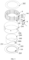
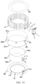
- control box accommodating cavity 3 includes a side wall 305 and an upper wall 302.
- control box accommodating cavity 3 is in a substantially cuboid shape.
- the side wall 305 is formed by enclosing a weldable material sheet.
- the side wall 305 is provided with a front hole or opening 307 and a back hole or opening 308.
- a front hole periphery 3072 on a front side 300 of the side wall 305 and the outer wall 201 of the pool body 2 are welded to form a sealed connection
- a back hole periphery 3082 on a back side 301 of the side wall 305 and the inner wall 200 of the pool body 2 are welded to form a sealed connection.
- a periphery 3022 of the upper wall 302 is welded to an upper end of the side wall 305.
- a lower edge 3062 of the side wall 305 and the pool bottom 203 are welded to form a sealed connection, and the lower edge 3062 of the side wall 305 is provided with a first hole or opening 306, such that the first hole 306 is located at a bottom of the control box accommodating cavity 3.
- the pool bottom 203 is provided with a second hole or opening 205 as an access opening, and the first hole 306 is in communication with the second hole 205, so as to allow the control box 4 to enter the control box accommodating cavity 3 from the pool bottom 203.
- control box accommodating cavity 3 isolates outside air from the inflatable chamber and may accommodate the control box 4, so as to facilitate mounting the control box 4 in the pool wall 2000 or removing the control box 4 from the pool wall 2000. Meanwhile, the control box accommodating cavity 3 is welded and fixed to the pool wall 2000, such that the control box accommodating cavity 3 may also limit a position of the control box 4 in the pool wall 2000, and the control box 4 is prevented from moving freely in the inflatable chamber and damaging components including a water supply pipeline.
- first hole 306 and the second hole 205 may also be provided on the pool wall 2000, and accordingly, the control box 4 enters the control box accommodating cavity from the first hole 306 and the second hole 205 provided on the pool wall 2000.
- first hole 306 and the second hole 205 are both in a rounded rectangle shape.
- the second hole 205 may be used as an air inlet, so as to allow an air pump of the control box 4 to suck the outside air from the air inlet, and then supply air to a wave making channel described below and provide a bubble massage function.
- the air pump in the control box 4 works, the outside air may be sucked into the control box 4 via the second hole 205 and the first hole 306, pressurized by the air pump, and conveyed into water in the water placement zone 5 via the pipeline, so as to form bubbles having a massage function.
- the front end surface 408 of the control box 4 is provided with a control box water inlet connector 10.
- the inner wall 200 of the pool body is provided with a pool water inlet connector 11.
- One end of the control box water inlet connector 10 is in communication with the water inlet pipe 412, and the other end of the control box water inlet connector is in communication with the pool water inlet connector 11.
- water in the water inlet pipe 412 of the control box 4 passes the control box water inlet connector 10 and the pool water inlet connector 11 successively, and thus enters the water placement zone of the pool body, where the water outlet pipe 411 is in communication with the water inlet pipe 412.
- the water outlet insertion end 901 is inserted into the water outlet slot 804.
- the first radial sealing member 809 is arranged between the water outlet insertion end 901 and a slot wall of the water outlet slot 804, and abuts against a side wall of the water outlet insertion end 901 and the slot wall of the water outlet slot 804 separately, such that the water outlet insertion end 901 is connected to the water outlet slot 804 in a sealed manner.
- the water outlet sealing assembly 800 further includes a first axial sealing member 808, the pool water outlet connector 9 further includes a first water outlet end surface 900 connected to the water outlet insertion end 901, and the first water outlet end surface 900 extends outward in the radial direction (the Z direction in FIG. 16 ) of the pool water outlet connector 9.
- the control box water outlet connector 8 further includes a second water outlet end surface 805 connected to the water outlet slot 804, and the second water outlet end surface 805 extends outward in the radial direction of the control box water outlet connector 8.
- the second water outlet end surface 805 is annular.
- the first water outlet end surface 900 and the second water outlet end surface 805 are arranged oppositely and at an interval in the axial direction (the R direction in FIG. 16 ) of the control box water outlet connector 8.
- the first axial sealing member 808 is located between the first water outlet end surface 900 and the second water outlet end surface 805, and is connected to the first water outlet end surface 900 and the second water outlet end surface 805 separately in the axial direction of the control box water outlet connector 8 in a sealed manner.
- first axial sealing member 808 is connected to the first water outlet end surface 900 and the second water outlet end surface 805 separately in a sealed manner, such that water leaking into the water outlet slot 804 may be effectively prevented from leaking between the first water outlet end surface 900 and the second water outlet end surface 805.
- the inflatable massage pool further includes a water outlet fixing member 913, at least a part of the water outlet fixing member 913 is located in the water outlet slot 804, an inner wall 913a of the water outlet fixing member 913 abuts against the outer wall of the water outlet insertion end 901, and an outer wall 913b of the water outlet fixing member 913 abuts against the slot wall of the water outlet slot 804.
- the water outlet insertion end 901 and the water outlet fixing member 913 jointly achieve reliable sealing between the control box water outlet connector 8 and the pool water outlet connector 9.
- An outer diameter of the water outlet insertion end 901 gradually decreases in a direction away from the first water outlet end surface 900, such that the water outlet fixing member 913 is gradually pressed in a process of fastening the water outlet insertion end 901 to the inner control box water outlet connector 801.
- the outer wall 913b of the water outlet fixing member 913 is provided with a water outlet sealing clamping groove 917, and the water outlet sealing clamping groove 917 accommodates the first radial sealing member 809.
- the first radial sealing member 809 is pressed between the water outlet fixing member 913 and the inner wall of the outer control box water outlet connector 802, so as to form a seal between the control box water outlet connector 8 and the pool water outlet connector 9.
- the first axial sealing member 808 includes a first protrusion 808a, and an inner wall of the first protrusion 808a is provided with a first clamping groove 808f.
- the outer wall 913b of the water outlet fixing member 913 is provided with a clamping part 915 in a protruding manner.
- the clamping part 915 is connected to the first clamping groove 808f in a clamped manner.
- the first protrusion 808a covers the clamping part 915, such that a certain tightness is ensured while relative fixation of the first axial sealing member 808 and the water outlet fixing member 913 is achieved.
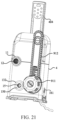
- the pool water outlet connector 9 is connected to the filter 911, and the filter 911 is fixed to the inner wall 200 of the pool body.
- the water in the water placement zone of the pool body first flows into the filter 911, and the impurities in the water are filtered by a filter element of the filter 911.
- the filtered water enters the control box 4, and optionally is heated by the heater 406, and then is returned to the water placement zone by means of the control box water inlet connector.
- the inflatable massage pool further includes a water bypass assembly 912.
- the water bypass assembly 912 is fixed to the inner wall 200 of the pool body and is in fluid communication with the filter 911.
- the water bypass assembly 912 is in communication by means of a pipeline arranged in the pool wall, such that the water pump 405 is not only in communication with the water in the water placement zone by means of the filter 911, but also in communication with the water in the water placement zone by means of the water bypass assembly 912.
- the filter 911 is blocked, the water in the water placement zone may still be sucked into the water pump 405 by means of the water bypass assembly 912.
- existence of the water bypass assembly 912 enables the user to easily leave the filter 911 without danger.
- the inflatable massage pool further includes a water inlet sealing assembly 100
- the control box 4 includes the control box water inlet connector 10
- the inner wall 200 of the pool body is provided with the pool water inlet connector 11
- the back side 301 of the control box accommodating cavity 3 is provided with the back hole 308, so as to allow the pool water inlet connector 11 to penetrate the back hole 308 to be connected to the control box water inlet connector 10 in a sealed manner by means of the water inlet sealing assembly 100, where the water inlet sealing assembly 100 simultaneously achieve a sealed connection between the control box water inlet connector 10 and the pool water inlet connector 11 in a radial direction (a Z direction in FIG. 22 ) and an axial direction (an R direction in FIG. 22 ) of the control box water inlet connector 10.
- the water inlet sealing assembly 100 includes a second radial sealing member 106.
- the second radial sealing member 106 is an annular sealing ring.
- the pool water inlet connector 11 includes a water inlet insertion end 111.
- the water inlet insertion end 111 is of a hollow tubular structure, and extends in the axial direction of the control box water inlet connector 10. A radial size of the water inlet insertion end 111 gradually increases in a direction facing an exterior of the control box.
- the pool water inlet connector 11 further includes a water inlet limiting part 113.
- the water inlet limiting part 113 is arranged at a periphery of a first water inlet end surface 110 and extends in the axial direction of the pool water inlet connector 11 so as to protrude from the first water inlet end surface 110.
- the water inlet insertion end 111 is inserted into the water inlet slot 103.
- the second radial sealing member 106 is arranged between the water inlet insertion end 111 and a slot wall of the water inlet slot 103, and abuts against the water inlet insertion end 111 and the slot wall of the water inlet slot 103 separately in the radial direction of the pool water inlet connector 11, such that the water inlet insertion end 111 is connected to the water inlet slot 103 in a sealed manner.
- the control box water inlet connector 10 includes an inner control box water inlet connector 101 and an outer control box water inlet connector 102.
- the outer control box water inlet connector 102 is arranged around the inner control box water inlet connector 101 so as to define the water inlet slot 103.
- a radial size of the outer control box water inlet connector 102 is greater than that of the inner control box water inlet connector 101. That is, a distance between the outer control box water inlet connector 102 and the inner control box water inlet connector 101 in the radial direction of the control box water inlet connector 10 forms the water inlet slot 103.
- One end of the water inlet slot 103 in the axial direction of the control box water inlet connector 10 is open and the other end of the water inlet slot is closed. An opening of the water inlet slot allows the water inlet insertion end 111 to be inserted into.
- the inner control box water inlet connector 101 is hollow and is provided with an outer thread 101a on an outer surface, and an inner wall of the water inlet insertion end 111 is provided with an inner thread 112 matching the outer thread 101a.
- the second radial sealing member 106 is located between an outer wall of the water inlet insertion end 111 and the slot wall of the water inlet slot 103, such that the water inlet slot 103 is connected to the water inlet insertion end 111 in a sealed manner.
- the inner control box water inlet connector 101 and the water inlet insertion end 111 may further be connected to each other in a sealed manner in known ways such as a flange connection or an interference fit connection.
- the control box water inlet connector 10 further includes a second water inlet end surface 104 connected to the water inlet slot 103, and the second water inlet end surface 104 extends outward in the radial direction of the control box water inlet connector 10.
- the second water inlet end surface 104 is annular.
- the first water inlet end surface 110 and the second water inlet end surface 104 are arranged oppositely and at an interval in the axial direction (the R direction in FIG. 22 ) of the control box water inlet connector 10.
- the second axial sealing member 105 is located between the first water inlet end surface 110 and the second water inlet end surface 104, and is connected to the first water inlet end surface 110 and the second water inlet end surface 104 separately in the axial direction of the control box water inlet connector 10 in a sealed manner.
- the inflatable massage pool further includes a water inlet fixing member 107, at least a part of the water inlet fixing member 107 is located in the water inlet slot 103, and an inner wall 107a of the water inlet fixing member 107 abuts against the outer wall of the water inlet insertion end 111 in the radial direction (the Z direction in FIG. 22 ) of the control box water inlet connector 10.
- An outer wall 107b of the water inlet fixing member 107 abuts against the slot wall of the water inlet slot 103 in the radial direction of the control box water inlet connector 10.
- the outer wall 107b of the water inlet fixing member 107 is provided with a water inlet sealing clamping groove 107c, and the water inlet sealing clamping groove 107c accommodates the second radial sealing member 106.
- the second radial sealing member 106 is pressed between the water inlet fixing member 107 and the inner wall of the outer control box water inlet connector 102, so as to form a sealed connection between the control box water inlet connector 10 and the pool water inlet connector 11.
- the second axial sealing member 105 includes a third protrusion 105a, and an inner wall of the third protrusion 105a is provided with a fourth clamping groove 105d.
- the outer wall 107b of the water inlet fixing member 107 is provided with a second clamping part 107d in a protruding manner.
- the second clamping part 107d is connected to the fourth clamping groove 105d in a clamped manner.
- the third protrusion 105a covers the second clamping part 107d, such that relative positions of the second axial sealing member 105 and the water inlet fixing member 107 are fixed, and sealing is provided.
- the second axial sealing member 105 includes a third connection part 105b and a fourth protrusion 105c.
- the third protrusion 105a and the fourth protrusion 105c are located at two ends of the third connection part 105b in the axial direction (the R direction in FIG. 22 ) of the second axial sealing member 105, respectively.
- a radial size of the third protrusion 105a is greater than that of the fourth protrusion 105c.
- the water inlet limiting part 113 presses the third protrusion 105a.
- the fourth protrusion 105c is clamped between the outer wall 107b of the water inlet fixing member 107 and the slot wall of the water inlet slot 103 in the radial direction (the Z direction in FIG.
- the third connection part 105b extends outward in the radial direction of the second axial sealing member 105 so as to be attached to the inner wall 200 of the pool body.
- a surface of the third connection part 105b and the inner wall 200 of the pool body are welded and sealed to prevent water from leaking from a joint between the second water inlet end surface 104 and the third connection part 105b.
- one side of the second water inlet end surface 104 facing the third connection part 105b is provided with a second water inlet clamping groove 104a, the second water inlet clamping groove 104a accommodates a first water inlet sealing ring 104b, and the first water inlet sealing ring 104b abuts against the third connection part 105b.
- a protective cover 12 is connected to the pool water inlet connector 11 in a clamped manner, so as to prevent objects in the water placement zone from entering the control box 4.
- the protective cover 12 is provided with a plurality of water inlet holes 122 and is connected to the pool water inlet connector 11 by means of its columnar part 120 in a clamped manner.
- the control box 4 is internally provided with a control box air inlet connector, and the inner wall 200 of the pool body is provided with a pool air inlet connector 15.
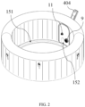
- One end of the pool air inlet connector 15 penetrates an air inlet hole 409 of the front end surface 408 of the control box 4, so as to be in communication with the control box air inlet connector, and the other end of the pool air inlet connector 15 is in fluid communication with a connection channel 152 of the pool body.
- the air pump 403 sucks air from the outside, pressurizes the air, and then conveys the air to a wave making channel 151 via the connection channel 152.
- the pressurized air supplies bubbles to a water storage zone via air injection holes 153 distributed on the wave making channel 151 so as to produce a massage effect.
- the inflatable massage pool further includes an air inlet sealing assembly 13
- the control box 4 includes a control box air inlet connector 14, the inner wall 200 of the pool body is provided with a pool air inlet connector 15, the back side 301 of the control box accommodating cavity 3 is provided with the back hole 308, the front end surface 408 of the control box 4 is provided with the air inlet hole 409, the back hole 308 is in communication with the air inlet hole 409, so as to allow the pool air inlet connector 15 to penetrate the back hole 308 and extend into the control box 4, and the control box air inlet connector 14 is connected to the pool air inlet connector 15 in a sealed manner by means of the air inlet sealing assembly 13, where the air inlet sealing assembly 13 provides sealing between the control box air inlet connector 14 and the pool air inlet connector 15.
- the air inlet sealing assembly 13 includes a radial sealing connector 131.
- the radial sealing connector includes a first air inlet end 133 and a second air inlet end 134.
- the control box air inlet connector 14 is sleeved with the first air inlet end 133
- the pool air inlet connector 15 is sleeved with the second air inlet end 134.
- An inner wall of the first air inlet end 133 is connected to an outer wall of the control box air inlet connector 14 in a radial direction (a Z direction in FIG.
- the radial sealing connector 131 further includes a contraction part 134a.
- One end of the contraction part 134a is connected to the first air inlet end 133 and the other end of the contraction part is connected to the second air inlet end 134.
- both the first air inlet end 133 and the second air inlet end 134 are of a hollow tubular structure having an equal diameter. Specifically, if a radial size of the first air inlet end 133 is greater than that of the second air inlet end 134, a radial size of the contraction part 134a gradually decreases in the axial direction, facing the pool body, of the radial sealing connector 131. That is, the radial size of the contraction part 134a gradually decreases from a maximum radial size at a joint with the first air inlet end 133 to a minimum radial size at a joint with the second air inlet end 134.
- the air inlet sealing assembly 13 further includes a first air inlet sealing ring 142.
- the inner wall of the first air inlet end 133 or the outer wall of the control box air inlet connector 14 is provided with a first air inlet clamping groove 140, and the first air inlet clamping groove 140 accommodates the first air inlet sealing ring 142.
- the first air inlet clamping groove 140 is provided on the outer wall of the control box air inlet connector 14, and the inner wall of the first air inlet end 133 and the first air inlet clamping groove 140 press the first air inlet sealing ring 142, such that the first air inlet end 133 of the radial sealing connector 131 is connected to the control box air inlet connector 14 in a sealed manner. Further, gas is prevented from leaking from a joint between the control box air inlet connector 14 and the radial sealing connector 131.
- the outer wall of the control box air inlet connector 14 is provided with an air inlet limiting part 144 in a protruding manner.
- the air inlet limiting part 144 and an end of the first air inlet end 133 of the radial sealing connector 131 jointly clamp the second air inlet sealing ring 143.
- the air inlet limiting part 144 is arranged around the outer wall of the control box air inlet connector 14, and a radial size of the air inlet limiting part 144 is greater than an outer contour size of the control box air inlet connector 14.
- the second air inlet sealing ring 143 in the second air inlet clamping groove 141 is pressed by the first wall 144a of the air inlet limiting part 144 and the end of the first air inlet end 133 separately in the axial direction of the control box air inlet connector 14, and then the control box air inlet connector 14 is connected to the radial sealing connector 131 in the axial direction of the control box air inlet connector 14 in a sealed manner.
- the threaded fastener 130 includes a first stop part 139, and the first stop part 139 extends in the radial direction (the Z direction in FIG. 27 ) of the threaded fastener 130.
- the air inlet limiting part 144 includes a first side 144a and a second side 144b facing away from each other in its axial direction (the R direction in FIG. 27 ).
- the first side 144a faces the second air inlet sealing ring 143 in the axial direction of the threaded fastener 130, and the second side 144b abuts against the first stop part 139.
- the air inlet sealing assembly 13 further includes a third air inlet sealing ring 157.
- the outer wall of the pool air inlet connector 15 or the inner wall of the second air inlet end 134 of the radial sealing connector 131 is provided with an air inlet sealing clamping groove 155, and the air inlet sealing clamping groove 155 accommodates the third air inlet sealing ring 157.
- the air inlet sealing clamping groove 155 is provided on the outer wall of the pool air inlet connector 15, and the inner wall of the second air inlet end 134 of the radial sealing connector 131 presses the third air inlet sealing ring 157, such that the second air inlet end 134 of the radial sealing connector 131 is connected to the pool air inlet connector 15 in a sealed manner.
- the inner wall of the second air inlet end 134 of the radial sealing connector 131 is connected to the outer wall of the pool air inlet connector 15 in a clamped manner.
- the inner wall of the second air inlet end 134 of the radial sealing connector 131 includes an air inlet clamping part 134d
- the outer wall of the pool air inlet connector 15 includes a first air inlet connection clamping groove 154.
- the air inlet clamping part 134d is connected to the first air inlet connection clamping groove 154 in a clamped manner.
- the air inlet clamping part 134d is obliquely arranged facing the first air inlet connection clamping groove 154 and abuts against a groove wall of the first air inlet connection clamping groove 154.
- the air inlet clamping part 134d is connected to the first air inlet connection clamping groove 154 in a clamped manner, such that the radial sealing connector 131 and the pool air inlet connector 15 are fixed relative to each other, and thus the radial sealing connector 131 is prevented from falling off from the pool air inlet connector 15.
- an inner periphery of the inner air inlet connection part 132a is provided with a plurality of recesses 132c
- outer peripheries of the contraction part 134a and the second air inlet end 134 are provided with a plurality of protrusions 134c
- the plurality of recesses 132c are connected to the plurality of protrusions 134c in a clamped manner, such that the axial sealing connector 132 and the radial sealing connector 131 are fixed relative to each other.
- the present application does not limit a connection way of the axial sealing connector 132 and the radial sealing connector 131.
- the inner periphery of the inner air inlet connection part 132a may be provided with a plurality of protrusions, the outer peripheries of the contraction part 134a and the second air inlet end 134 are provided with a plurality of recesses, and the axial sealing connector 132 is connected to the radial sealing connector 131 through a concave-convex fit.
- the axial sealing connector 132 further includes an outer air inlet sealing end surface 132b.
- the outer air inlet sealing end surface 132b is connected to the inner air inlet connection part 132a.
- the outer air inlet sealing end surface 132b is attached to the inner wall 200 of the pool body in the axial direction (the R direction in FIG. 27 ) of the axial sealing connector 132.
- the outer air inlet sealing end surface 132b is welded to the inner wall 200 of the pool body, such that gas is prevented from leaking between the outer air inlet sealing end surface 132b and the inner wall 200 of the pool body.
- the outer wall of the pool air inlet connector 15 is provided with an air inlet protrusion 156 in a protruding manner, and the second air inlet end 134 and one end of the inner connection part 132a facing the pool body are flush with each other in the radial direction of the pool air inlet connector 15 and abut against the air inlet protrusion 156.
- the inflatable massage pool further includes an air inlet connector 150.
- the pool air inlet connector 15 is sleeved with the air inlet connector 150.
- the outer wall of the pool air inlet connector 15 is provided with the air inlet protrusion 156 in a protruding manner.
- the inner air inlet connection part 132a of the axial sealing connector 132 includes an annular end part 132d.
- the annular end part 132d is arranged at one side of the inner air inlet connection part 132a in the axial direction (the R direction in FIG. 27 ) of the pool air inlet connector 15 and facing the pool body.
- an outer end surface of the air inlet connector 150 and the outer sealing end surface 132b of the axial sealing connector 132 are oppositely arranged in the axial direction of the pool air inlet connector 15.
- the air inlet connector 150 is configured to be connected to the connection channel 152 connected to the wave making channel 151, such that gas from the air pump in the control box enters the wave making channel 151, and a wave-making massage function is provided for a user.
- the inflatable chamber needs to be inflated by using the air pump in the control box, such that the inflatable massage pool expands to a set shape, so as to form the water placement zone for accommodating water.
- the control box of the inflatable massage pool may be in fluid communication with the inflatable chamber. That is, the air pump in the control box may pump gas into the inflatable chamber via a control box inflation connector and an accommodating cavity inflation connector of the control box accommodating cavity, so as to inflate the inflatable chamber.
- the inflatable massage pool according to the invention further includes an inflation sealing assembly 16,
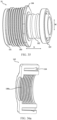
- the control box 4 includes the control box inflation connector 17, a side wall 305 of the control box accommodating cavity 3 is provided with the accommodating cavity inflation connector 18, and the control box 4 is provided with an inner inflation hole 407, such that the accommodating cavity inflation connector 18 extends into the inner inflation hole 407 to be connected to the control box inflation connector 17 by means of the inflation sealing assembly 16 in a sealed manner.
- the accommodating cavity inflation connector 18 includes a first connection part 181
- the control box inflation connector 17 includes an inflation insertion end 17b
- the inflation insertion end 17b is sleeved with the first connection part 181
- an inner wall of the first connection part 181 is connected to an outer wall of the inflation insertion end 17b in a sealed manner in a radial direction (an M direction in FIG. 33 ) of the accommodating cavity inflation connector 18.
- the control box inflation connector 17 further includes a pipeline connection end 17a, and the pipeline connection end 17a is connected to the inflation insertion end 17b.
- the pipeline connection end 17a is inserted into an inflation pipe 414, and an outer wall of the pipeline connection end 17a is provided with an inflation connection clamping groove 173, so as to accommodate a sealing ring, such that the control box inflation connector 17 is connected to the inflation pipe 414 in a sealed manner.
- the inflation sealing assembly 16 includes a first inflation sealing ring 172a.
- the inner wall of the first connection part 181 or the outer wall of the inflation insertion end 17b is provided with a first inflation clamping groove 172.
- the first inflation clamping groove 172 accommodates the first inflation sealing ring 172a.
- the first inflation clamping groove 172 is provided on the outer wall of the inflation insertion end 17b, and the inner wall of the first connection part 181 presses the first inflation sealing ring 172a in the first inflation clamping groove 172 in the radial direction of the control box inflation connector 17, such that the inner wall of the first connection part 181 is closely attached to the outer wall of the inflation insertion end 17b, and thus the control box inflation connector 17 is connected to the accommodating cavity inflation connector 18 in a sealed manner.
- the inflation sealing assembly 16 further includes a second inflation sealing ring 171a.
- the inner wall of the first connection part 181 or the outer wall of the inflation insertion end 17b is provided with a second inflation clamping groove 171.
- the second inflation clamping groove 171 accommodates the second inflation sealing ring 171a.
- the first inflation clamping groove 172 and the second inflation clamping groove 171 are provided at an interval in an axial direction (an N direction in FIG. 24 ) of the control box inflation connector 17.
- the second inflation clamping groove 171 is provided on the outer wall of the inflation insertion end 17b, and the inner wall of the first connection part 181 presses the second inflation sealing ring 171a in the second inflation clamping groove 171 in the radial direction of the accommodating cavity inflation connector 18, such that the inner wall of the first connection part 181 is closely attached to the outer wall of the inflation insertion end 17b, and thus the control box inflation connector 17 is connected to the accommodating cavity inflation connector 18 in a sealed manner.
- the outer wall of the inflation insertion end 17b is provided with an inflation limiting part 170 in a protruding manner.
- the inflation limiting part 170 and the inner wall of the first connection part 181 jointly clamp the second inflation sealing ring 171a.
- the inflation limiting part 170 is arranged around the outer wall of the inflation insertion end 17b, and an outer contour size of the inflation limiting part 170 is greater than that of the inflation insertion end 17b.
- the inflation limiting part 170 includes a first limiting wall 170a and a second limiting wall 170b facing away from each other in the axial direction of the accommodating cavity inflation connector 18, and the first limiting wall 170a is also a groove wall of the second inflation clamping groove 171.
- the first limiting wall 170a abuts against an end of the first connection part 181 of the accommodating cavity inflation connector 18 in the axial direction of the accommodating cavity inflation connector 18, such that the second inflation sealing ring 171a is pressed together by the inner wall of the first connection part 181 and the first limiting wall 170a, and thus the control box inflation connector 17 is connected to the accommodating cavity inflation connector 18 in a sealed manner.
- the inflatable massage pool further includes an inflation fastener 160.
- the first connection part 181 of the accommodating cavity inflation connector 18 is sleeved with the inflation fastener 160, and the inflation fastener is in threaded connection with the first connection part 181.
- the outer wall of the first connection part 181 of the accommodating cavity inflation connector 18 is provided with an outer thread 180
- the inner wall of the inflation fastener 160 is provided with an inner thread 160a.
- the outer thread 180 is connected to the inner thread 160a.
- the first connection part 181 of the accommodating cavity inflation connector 18 is clamped by the inflation fastener 160 and the inflation insertion end 17b of the control box inflation connector 17, such that relative movement of the control box inflation connector 17 and the accommodating cavity inflation connector 18 is limited, and then connection reliability of the control box inflation connector 17 and the accommodating cavity inflation connector 18 is ensured.
- the first limiting wall 170a of the inflation limiting part 170 abuts against the end of the first connection part 181 of the accommodating cavity inflation connector 18, and the second limiting wall 170b abuts against the first inflation stop part 160b, such that relative fixation of the control box inflation connector 17, the accommodating cavity inflation connector 18 and the inflation fastener 160 is achieved, and then a sealed connection between the control box inflation connector 17 and the accommodating cavity inflation connector 18 is ensured.
- the first connection part 181 of the accommodating cavity inflation connector 18 includes a second inflation stop part 184.
- the second inflation stop part 184 extends in the radial direction of the accommodating cavity inflation connector 18.
- the second inflation stop part 184 abuts against one end of the inflation fastener 160 in the axial direction (the N direction in FIG. 33 ) of the accommodating cavity inflation connector 18 and away from the first inflation stop part 160b.
- the second inflation stop part 184 abuts against the end of the inflation fastener, and thus further the inflation fastener 160 and the first connection part 181 are fixed relative to each other, so as to prevent the inflation fastener 160 from being disengaged from the first connection part 181.
- the inflation fastener 160 includes a first fastener 162 and a second fastener 163.
- the first fastener 162 is provided with an inflation clamping groove 164
- the second fastener 163 is provided with an inflation protrusion 165.
- the inflation protrusion 165 is connected to the inflation clamping groove 164 in a clamped manner.
- both the first fastener 162 and the second fastener 163 are semicircular, and the first fastener 162 and the second fastener 163 are spliced to form a complete inflation fastener 160.
- the inflation fastener 160 fastens the connection between the control box inflation connector 17 and the accommodating cavity inflation connector 18 so as to prevent the control box inflation connector 17 and the accommodating cavity inflation connector 18 from being disengaged.
- the inflatable massage pool further includes an axial inflation sealing member 161
- the axial inflation sealing member 161 includes an inner inflation connection part 161a
- the accommodating cavity inflation connector 18 further includes a second connection part 182 connected to the first connection part 181.
- the second connection part 182 is sleeved with the inner inflation connection part 161a, and the inner inflation connection part is connected to the second connection part 182 in a clamped manner.
- an inner wall of the inner inflation connection part 161a is provided with an inflation sealing clamping groove 161c
- an outer wall of the second connection part 182 is provided with an inflation clamping part 185 in a protruding manner
- the inflation clamping part 185 is connected to the inflation sealing clamping groove 161c of the inner inflation connection part 161a in a clamped manner, such that the axial inflation sealing member 161 and the accommodating cavity inflation connector 18 are fixed and sealed relative to each other.
- the axial inflation sealing member 161 further includes an outer inflation sealing end surface 161b.
- the outer inflation sealing end surface 161b is connected to the inner inflation connection part 161a.
- the outer inflation sealing end surface 161b extends outward in the radial direction (the M direction in FIG. 24 ) of the accommodating cavity inflation connector 18 so as to be attached and connected to the side wall 305 of the control box accommodating cavity in the axial direction (the N direction in FIG. 33 ) of the accommodating cavity inflation connector 18.
- the outer inflation sealing end surface 161b is fixed to the side wall 305 of the control box accommodating cavity through welding, such that gas is prevented from leaking from the joint between the accommodating cavity inflation connector 18 and the side wall 305 of the control box accommodating cavity.
Landscapes
- Health & Medical Sciences (AREA)
- Public Health (AREA)
- Epidemiology (AREA)
- Pain & Pain Management (AREA)
- Physical Education & Sports Medicine (AREA)
- Rehabilitation Therapy (AREA)
- Life Sciences & Earth Sciences (AREA)
- Animal Behavior & Ethology (AREA)
- General Health & Medical Sciences (AREA)
- Veterinary Medicine (AREA)
- Engineering & Computer Science (AREA)
- Architecture (AREA)
- Civil Engineering (AREA)
- Structural Engineering (AREA)
- Massaging Devices (AREA)
Claims (13)
- Aufblasbares Massagebecken (1), umfassend:eine Außenwand (201), die einen oberen Abschnitt und einen unteren Abschnitt umfasst;eine Innenwand (200), die einen oberen Abschnitt und einen unteren Abschnitt umfasst;eine obere Wand (202), die mit dem oberen Abschnitt der Außenwand (201) und dem oberen Abschnitt der Innenwand (200) verbunden ist;einen Beckenboden (203), der mit dem unteren Abschnitt der Außenwand (201) und dem unteren Abschnitt der Innenwand (200) verbunden ist,einen Wasseraufnahmebehälter (5), der durch die Innenwand (200) und den Beckenboden (203) definiert wird;eine aufblasbare Kammer, die durch die Außenwand (201), die Innenwand (200), die obere Wand (202) und den Beckenboden (203) definiert wird;gekennzeichnet durcheine Unterbringungswand (340), die mit der Innenwand (200), der Außenwand (201) und dem Beckenboden (203) verbunden ist, um einen Unterbringungshohlraum (3) von der aufblasbaren Kammer abdichtend zu trennen, und einen Unterbringungshohlraum-Aufblasanschluss (18) umfasst, einen Steuerkasten (4), der im Unterbringungshohlraum (3) angeordnet ist und einen Steuerkasten-Aufblasanschluss (17) umfasst; undeine Aufblasdichtungsanordnung (16), die den Unterbringungshohlraum-Aufblasanschluss (18) abdichtend mit dem Steuerkasten-Aufblasanschluss (17) verbindet.
- Aufblasbares Massagebecken (1) nach Anspruch 1, wobei die Unterbringungswand (340) eine obere Wand (302) umfasst, die der oberen Wand (202) einer Beckenwand (2000) zugewandt ist.
- Aufblasbares Massagebecken (1) nach Anspruch 1 oder 2, wobei die Unterbringungswand (340) eine Seitenwand (305) umfasst, die derart geformt ist, dass sie den Steuerkasten (4) umgibt, vorzugsweise, wobei die Seitenwand (305) aus einer einzigen Platte ausgebildet ist.
- Aufblasbares Massagebecken (1) nach einem der Ansprüche 1 bis 3, ferner umfassend eine Schutzwand (7) zwischen der Unterbringungswand (340) und dem Steuerkasten (4),vorzugsweise, wobei die Schutzwand (7) aus einer einzigen Platte ausgebildet ist, vorzugsweise,wobei die Schutzwand (7) mit sowohl der Außenwand (201) als auch der Innenwand (200) der Beckenwand (2000) verbunden ist.
- Aufblasbares Massagebecken (1) nach einem der Ansprüche 1 bis 4, wobei der Beckenkörper (2) eine Zugangsöffnung (205) umfasst, durch die der Steuerkasten (4) in den Unterbringungshohlraum (3) eingeführt wird,
vorzugsweise, wobei sich die Zugangsöffnung (205) im Beckenboden (203) befindet. - Aufblasbares Massagebecken (1) nach einem der Ansprüche 1 bis 5, wobei der Steuerkasten (4) eine Bedientafel (404) umfasst, und
wobei die Beckenwand (2000) eine Öffnung (206) umfasst, durch die sich die Bedientafel (4040) aus der Beckenwand (2000) heraus erstreckt. - Aufblasbares Massagebecken (1) nach einem der Ansprüche 1 bis 6, wobei der Steuerkasten (4) dazu eingerichtet ist, Wasser in einem Wasseraufnahmebehälter (5), der durch die Beckenwand (2000) und den Beckenboden (203) definiert wird, umzuwälzen,vorzugsweise, wobei die Beckenwand (2000) einen Wassereinlass (11) und einen Wasserauslass (9) auf einer Seite des Wasseraufnahmebehälters (5) umfasst,vorzugsweise, wobei der Steuerkasten (4) einen Wassereinlass (10) und einen Wasserauslass (8) umfasst, die jeweils mit dem Wasseraufnahmebehälter (5) über den Wassereinlass (11) und den Wasserauslass (9) der Beckenwand (2000) in Verbindung stehen.
- Aufblasbares Massagebecken (1) nach Anspruch 7, ferner umfassend eine Wasserauslass-Dichtungsanordnung (800) zum abdichtenden Verbinden des Wasserauslasses (9) der Beckenwand (2000) und des Wasserauslasses (8) des Steuerkastens (4),
vorzugsweise, wobei der Steuerkasten (4) einen Steuerkasten-Wasserauslassanschluss (8) umfasst, eine Innenwand (200) des Beckenkörpers einen Becken-Wasserauslassanschluss (9) umfasst, die Unterbringungswand (340) ein hinteres Loch (308) umfasst, durch das der Becken-Wasserauslassanschluss (9) dringt, und der Becken-Wasserauslassanschluss (9) durch die Wasserauslass-Dichtungsanordnung (800) abdichtend mit dem Steuerkasten-Wasserauslassanschluss (8) verbunden ist. - Aufblasbares Massagebecken (1) nach Anspruch 7 oder 8, ferner umfassend eine Wassereinlass-Dichtungsanordnung (100) zum abdichtenden Verbinden des Wassereinlasses (11) der Beckenwand (2000) und des Wassereinlasses (10) des Steuerkastens (4),
vorzugsweise, wobei der Steuerkasten (4) einen Steuerkasten-Wassereinlassanschluss (10) umfasst, eine Innenwand (200) des Beckenkörpers (2) einen Becken-Wassereinlassanschluss (11) umfasst, die Unterbringungswand (340) ein hinteres Loch (308) umfasst, durch das der Becken-Wassereinlassanschluss (11) dringt, und der Becken-Wassereinlassanschluss (11) durch die Wassereinlass-Dichtungsanordnung (100) abdichtend mit dem Steuerkasten-Wassereinlassanschluss (10) verbunden ist. - Aufblasbares Massagebecken (1) nach einem der Ansprüche 1 bis 9, wobei der Steuerkasten (4) dazu eingerichtet ist, Luft in einen Wasseraufnahmebehälter (5), der durch die Beckenwand (2000) und den Beckenboden (203) definiert wird, einzuspeisen,vorzugsweise, wobei die Beckenwand (2000) einen Lufteinlass (15) auf der Seite des Wasseraufnahmebehälters umfasst,vorzugsweise, wobei der Steuerkasten (4) einen Lufteinlass (409) umfasst, der mit dem Wasseraufnahmebehälter (5) über den Lufteinlass (15) der Beckenwand in Verbindung steht.
- Aufblasbares Massagebecken (1) nach Anspruch 10, ferner umfassend eine Lufteinlass-Dichtungsanordnung (13), wobei der Steuerkasten (4) einen Steuerkasten-Lufteinlassanschluss (14) umfasst, eine Innenwand (200) des Beckenkörpers einen Becken-Lufteinlassanschluss (15) umfasst, die Unterbringungswand (340) ein hinteres Loch (308) umfasst, durch das der Becken-Lufteinlassanschluss (15) dringt, und der Steuerkasten-Lufteinlassanschluss (14) durch die Lufteinlass-Dichtungsanordnung (13) abdichtend mit dem Becken-Lufteinlassanschluss (15) verbunden ist.
- Aufblasbares Massagebecken nach Anspruch 1, wobei der Unterbringungshohlraum-Aufblasanschluss (18) ein erstes Verbindungsteil (181) umfasst, der Steuerkasten-Aufblasanschluss (17) ein Aufblaseinführende (17b) umfasst, das Aufblaseinführende (17b) mit dem ersten Verbindungsteil (181) ummantelt ist und eine Innenwand des ersten Verbindungsteils (181) und eine Außenwand des Aufblaseinführendes (17b) abgedichtet sind.
- Aufblasbares Massagebecken (1) nach Anspruch 1 bis 12, wobei die Aufblasdichtungsanordnung (16) umfasst:eine erste Aufblasklemmnut (172), die auf der Innenwand des ersten Verbindungsteils (181) oder der Außenwand des Aufblaseinführendes (17b) vorgesehen ist; undeinen ersten Aufblasdichtring (172a), der in der ersten Aufblasklemmnut (172) untergebracht ist,vorzugsweise, wobei die Aufblasdichtungsanordnung (16) ferner umfasst:eine zweite Aufblasklemmnut (171), die auf der Innenwand des ersten Verbindungsteils (181) oder der Außenwand des Aufblaseinführendes (17b) vorgesehen ist; undeinen zweiten Aufblasdichtring (171a), der in der zweiten Aufblasklemmnut (171) untergebracht ist.
Priority Applications (2)
| Application Number | Priority Date | Filing Date | Title |
|---|---|---|---|
| EP25168024.5A EP4555993A3 (de) | 2022-12-12 | 2023-09-25 | Aufblasbares massagebecken |
| US18/386,873 US20240191528A1 (en) | 2022-12-12 | 2023-11-03 | Inflatable massage pool |
Applications Claiming Priority (2)
| Application Number | Priority Date | Filing Date | Title |
|---|---|---|---|
| CN202223334343.0U CN219219926U (zh) | 2022-12-12 | 2022-12-12 | 充气按摩水池 |
| CN202321526309.5U CN220377954U (zh) | 2023-06-14 | 2023-06-14 | 一种充气按摩水池 |
Related Child Applications (2)
| Application Number | Title | Priority Date | Filing Date |
|---|---|---|---|
| EP25168024.5A Division EP4555993A3 (de) | 2022-12-12 | 2023-09-25 | Aufblasbares massagebecken |
| EP25168024.5A Division-Into EP4555993A3 (de) | 2022-12-12 | 2023-09-25 | Aufblasbares massagebecken |
Publications (2)
| Publication Number | Publication Date |
|---|---|
| EP4385484A1 EP4385484A1 (de) | 2024-06-19 |
| EP4385484B1 true EP4385484B1 (de) | 2025-07-09 |
Family
ID=88192308
Family Applications (2)
| Application Number | Title | Priority Date | Filing Date |
|---|---|---|---|
| EP23199386.6A Active EP4385484B1 (de) | 2022-12-12 | 2023-09-25 | Aufblasbares massagebecken |
| EP25168024.5A Pending EP4555993A3 (de) | 2022-12-12 | 2023-09-25 | Aufblasbares massagebecken |
Family Applications After (1)
| Application Number | Title | Priority Date | Filing Date |
|---|---|---|---|
| EP25168024.5A Pending EP4555993A3 (de) | 2022-12-12 | 2023-09-25 | Aufblasbares massagebecken |
Country Status (1)
| Country | Link |
|---|---|
| EP (2) | EP4385484B1 (de) |
Family Cites Families (5)
| Publication number | Priority date | Publication date | Assignee | Title |
|---|---|---|---|---|
| US5718007A (en) * | 1996-05-14 | 1998-02-17 | Loyd; Casey | Portable spa with easy access maintenance tray |
| CN200980613Y (zh) * | 2006-12-13 | 2007-11-28 | 东辉塑胶(上海)有限公司 | 一种按摩水池 |
| CN201175295Y (zh) * | 2008-03-26 | 2009-01-07 | 上海美欣塑胶制品有限公司 | 可移式泡泡按摩充气浴池 |
| CN209437123U (zh) * | 2018-04-13 | 2019-09-27 | 昆山亚宏塑胶有限公司 | 方形充气按摩浴缸 |
| CN112443180A (zh) * | 2019-09-03 | 2021-03-05 | 东辉休闲运动用品(上海)有限公司 | 一种控制箱以及按摩水池 |
-
2023
- 2023-09-25 EP EP23199386.6A patent/EP4385484B1/de active Active
- 2023-09-25 EP EP25168024.5A patent/EP4555993A3/de active Pending
Also Published As
| Publication number | Publication date |
|---|---|
| EP4555993A3 (de) | 2025-08-13 |
| EP4385484A1 (de) | 2024-06-19 |
| EP4555993A2 (de) | 2025-05-21 |
Similar Documents
| Publication | Publication Date | Title |
|---|---|---|
| US20240191528A1 (en) | Inflatable massage pool | |
| US5236581A (en) | Spa with filter assembly accessible through its coping lip | |
| ES2837052T3 (es) | Balneario inflable | |
| EP1138307B1 (de) | Tragbare Whirlpoolwanne | |
| EP3077606B1 (de) | Aufblasbares schwimmbecken | |
| EP1219280A2 (de) | Tragbare Whirlpoolwanne | |
| US20220325546A1 (en) | Inflatable spa | |
| EP4385484B1 (de) | Aufblasbares massagebecken | |
| US6295663B1 (en) | Pressurized solar heated shower | |
| CN220377954U (zh) | 一种充气按摩水池 | |
| US20260085535A1 (en) | Pool having built-in seat | |
| EP4325001A1 (de) | Nicht aufblasbares oberirdisches schwimmbecken | |
| US20240189180A1 (en) | Inflatable massage pool | |
| KR101752747B1 (ko) | 고압산소 치료용 챔버 | |
| CN223853924U (zh) | 一种不充气按摩水池 | |
| KR101752744B1 (ko) | 고압산소 치료용 챔버 | |
| CN222350357U (zh) | 一种非充气冲浪按摩水池 | |
| CN223880844U (zh) | 一种按摩水池 | |
| CN218346998U (zh) | 新型水池 | |
| US20260115097A1 (en) | Interchangeable jet modules for a spa and/or bathing system | |
| KR200349012Y1 (ko) | 에어튜브형 분해조립식 월풀욕조 | |
| KR20050079647A (ko) | 에어튜브형 분해조립식 월풀욕조 |
Legal Events
| Date | Code | Title | Description |
|---|---|---|---|
| PUAI | Public reference made under article 153(3) epc to a published international application that has entered the european phase |
Free format text: ORIGINAL CODE: 0009012 |
|
| STAA | Information on the status of an ep patent application or granted ep patent |
Free format text: STATUS: THE APPLICATION HAS BEEN PUBLISHED |
|
| AK | Designated contracting states |
Kind code of ref document: A1 Designated state(s): AL AT BE BG CH CY CZ DE DK EE ES FI FR GB GR HR HU IE IS IT LI LT LU LV MC ME MK MT NL NO PL PT RO RS SE SI SK SM TR |
|
| STAA | Information on the status of an ep patent application or granted ep patent |
Free format text: STATUS: REQUEST FOR EXAMINATION WAS MADE |
|
| STAA | Information on the status of an ep patent application or granted ep patent |
Free format text: STATUS: EXAMINATION IS IN PROGRESS |
|
| 17P | Request for examination filed |
Effective date: 20240918 |
|
| RBV | Designated contracting states (corrected) |
Designated state(s): AL AT BE BG CH CY CZ DE DK EE ES FI FR GB GR HR HU IE IS IT LI LT LU LV MC ME MK MT NL NO PL PT RO RS SE SI SK SM TR |
|
| 17Q | First examination report despatched |
Effective date: 20241022 |
|
| GRAP | Despatch of communication of intention to grant a patent |
Free format text: ORIGINAL CODE: EPIDOSNIGR1 |
|
| STAA | Information on the status of an ep patent application or granted ep patent |
Free format text: STATUS: GRANT OF PATENT IS INTENDED |
|
| INTG | Intention to grant announced |
Effective date: 20250206 |
|
| GRAJ | Information related to disapproval of communication of intention to grant by the applicant or resumption of examination proceedings by the epo deleted |
Free format text: ORIGINAL CODE: EPIDOSDIGR1 |
|
| STAA | Information on the status of an ep patent application or granted ep patent |
Free format text: STATUS: EXAMINATION IS IN PROGRESS |
|
| GRAS | Grant fee paid |
Free format text: ORIGINAL CODE: EPIDOSNIGR3 |
|
| STAA | Information on the status of an ep patent application or granted ep patent |
Free format text: STATUS: GRANT OF PATENT IS INTENDED |
|
| GRAP | Despatch of communication of intention to grant a patent |
Free format text: ORIGINAL CODE: EPIDOSNIGR1 |
|
| INTC | Intention to grant announced (deleted) | ||
| RIN1 | Information on inventor provided before grant (corrected) |
Inventor name: ZENG, XIANGLIN |
|
| GRAA | (expected) grant |
Free format text: ORIGINAL CODE: 0009210 |
|
| STAA | Information on the status of an ep patent application or granted ep patent |
Free format text: STATUS: THE PATENT HAS BEEN GRANTED |
|
| INTG | Intention to grant announced |
Effective date: 20250523 |
|
| AK | Designated contracting states |
Kind code of ref document: B1 Designated state(s): AL AT BE BG CH CY CZ DE DK EE ES FI FR GB GR HR HU IE IS IT LI LT LU LV MC ME MK MT NL NO PL PT RO RS SE SI SK SM TR |
|
| REG | Reference to a national code |
Ref country code: GB Ref legal event code: FG4D |
|
| REG | Reference to a national code |
Ref country code: CH Ref legal event code: EP |
|
| REG | Reference to a national code |
Ref country code: IE Ref legal event code: FG4D |
|
| REG | Reference to a national code |
Ref country code: DE Ref legal event code: R096 Ref document number: 602023004678 Country of ref document: DE |
|
| PGFP | Annual fee paid to national office [announced via postgrant information from national office to epo] |
Ref country code: DE Payment date: 20250916 Year of fee payment: 3 |
|
| PGFP | Annual fee paid to national office [announced via postgrant information from national office to epo] |
Ref country code: FR Payment date: 20250929 Year of fee payment: 3 Ref country code: AT Payment date: 20251020 Year of fee payment: 3 |
|
| REG | Reference to a national code |
Ref country code: NL Ref legal event code: MP Effective date: 20250709 |
|
| PG25 | Lapsed in a contracting state [announced via postgrant information from national office to epo] |
Ref country code: PT Free format text: LAPSE BECAUSE OF FAILURE TO SUBMIT A TRANSLATION OF THE DESCRIPTION OR TO PAY THE FEE WITHIN THE PRESCRIBED TIME-LIMIT Effective date: 20251110 |
|
| PG25 | Lapsed in a contracting state [announced via postgrant information from national office to epo] |
Ref country code: NL Free format text: LAPSE BECAUSE OF FAILURE TO SUBMIT A TRANSLATION OF THE DESCRIPTION OR TO PAY THE FEE WITHIN THE PRESCRIBED TIME-LIMIT Effective date: 20250709 |
|
| REG | Reference to a national code |
Ref country code: AT Ref legal event code: MK05 Ref document number: 1811159 Country of ref document: AT Kind code of ref document: T Effective date: 20250709 |
|
| PG25 | Lapsed in a contracting state [announced via postgrant information from national office to epo] |
Ref country code: IS Free format text: LAPSE BECAUSE OF FAILURE TO SUBMIT A TRANSLATION OF THE DESCRIPTION OR TO PAY THE FEE WITHIN THE PRESCRIBED TIME-LIMIT Effective date: 20251109 |
|
| PG25 | Lapsed in a contracting state [announced via postgrant information from national office to epo] |
Ref country code: NO Free format text: LAPSE BECAUSE OF FAILURE TO SUBMIT A TRANSLATION OF THE DESCRIPTION OR TO PAY THE FEE WITHIN THE PRESCRIBED TIME-LIMIT Effective date: 20251009 |
|
| REG | Reference to a national code |
Ref country code: LT Ref legal event code: MG9D |
|
| PG25 | Lapsed in a contracting state [announced via postgrant information from national office to epo] |
Ref country code: AT Free format text: LAPSE BECAUSE OF FAILURE TO SUBMIT A TRANSLATION OF THE DESCRIPTION OR TO PAY THE FEE WITHIN THE PRESCRIBED TIME-LIMIT Effective date: 20250709 |
|
| PG25 | Lapsed in a contracting state [announced via postgrant information from national office to epo] |
Ref country code: FI Free format text: LAPSE BECAUSE OF FAILURE TO SUBMIT A TRANSLATION OF THE DESCRIPTION OR TO PAY THE FEE WITHIN THE PRESCRIBED TIME-LIMIT Effective date: 20250709 |
|
| PG25 | Lapsed in a contracting state [announced via postgrant information from national office to epo] |
Ref country code: HR Free format text: LAPSE BECAUSE OF FAILURE TO SUBMIT A TRANSLATION OF THE DESCRIPTION OR TO PAY THE FEE WITHIN THE PRESCRIBED TIME-LIMIT Effective date: 20250709 |
|
| PG25 | Lapsed in a contracting state [announced via postgrant information from national office to epo] |
Ref country code: GR Free format text: LAPSE BECAUSE OF FAILURE TO SUBMIT A TRANSLATION OF THE DESCRIPTION OR TO PAY THE FEE WITHIN THE PRESCRIBED TIME-LIMIT Effective date: 20251010 |
|
| PG25 | Lapsed in a contracting state [announced via postgrant information from national office to epo] |
Ref country code: SE Free format text: LAPSE BECAUSE OF FAILURE TO SUBMIT A TRANSLATION OF THE DESCRIPTION OR TO PAY THE FEE WITHIN THE PRESCRIBED TIME-LIMIT Effective date: 20250709 |
|
| PG25 | Lapsed in a contracting state [announced via postgrant information from national office to epo] |
Ref country code: LV Free format text: LAPSE BECAUSE OF FAILURE TO SUBMIT A TRANSLATION OF THE DESCRIPTION OR TO PAY THE FEE WITHIN THE PRESCRIBED TIME-LIMIT Effective date: 20250709 |
|
| PG25 | Lapsed in a contracting state [announced via postgrant information from national office to epo] |
Ref country code: PL Free format text: LAPSE BECAUSE OF FAILURE TO SUBMIT A TRANSLATION OF THE DESCRIPTION OR TO PAY THE FEE WITHIN THE PRESCRIBED TIME-LIMIT Effective date: 20250709 Ref country code: BG Free format text: LAPSE BECAUSE OF FAILURE TO SUBMIT A TRANSLATION OF THE DESCRIPTION OR TO PAY THE FEE WITHIN THE PRESCRIBED TIME-LIMIT Effective date: 20250709 |
|
| PG25 | Lapsed in a contracting state [announced via postgrant information from national office to epo] |
Ref country code: RS Free format text: LAPSE BECAUSE OF FAILURE TO SUBMIT A TRANSLATION OF THE DESCRIPTION OR TO PAY THE FEE WITHIN THE PRESCRIBED TIME-LIMIT Effective date: 20251009 |
|
| PG25 | Lapsed in a contracting state [announced via postgrant information from national office to epo] |
Ref country code: ES Free format text: LAPSE BECAUSE OF FAILURE TO SUBMIT A TRANSLATION OF THE DESCRIPTION OR TO PAY THE FEE WITHIN THE PRESCRIBED TIME-LIMIT Effective date: 20250709 |
|
| PG25 | Lapsed in a contracting state [announced via postgrant information from national office to epo] |
Ref country code: RO Free format text: LAPSE BECAUSE OF FAILURE TO SUBMIT A TRANSLATION OF THE DESCRIPTION OR TO PAY THE FEE WITHIN THE PRESCRIBED TIME-LIMIT Effective date: 20250709 |
|
| PG25 | Lapsed in a contracting state [announced via postgrant information from national office to epo] |
Ref country code: SM Free format text: LAPSE BECAUSE OF FAILURE TO SUBMIT A TRANSLATION OF THE DESCRIPTION OR TO PAY THE FEE WITHIN THE PRESCRIBED TIME-LIMIT Effective date: 20250709 |
|
| PG25 | Lapsed in a contracting state [announced via postgrant information from national office to epo] |
Ref country code: DK Free format text: LAPSE BECAUSE OF FAILURE TO SUBMIT A TRANSLATION OF THE DESCRIPTION OR TO PAY THE FEE WITHIN THE PRESCRIBED TIME-LIMIT Effective date: 20250709 |
|
| PG25 | Lapsed in a contracting state [announced via postgrant information from national office to epo] |
Ref country code: IT Free format text: LAPSE BECAUSE OF FAILURE TO SUBMIT A TRANSLATION OF THE DESCRIPTION OR TO PAY THE FEE WITHIN THE PRESCRIBED TIME-LIMIT Effective date: 20250709 |
|
| PG25 | Lapsed in a contracting state [announced via postgrant information from national office to epo] |
Ref country code: CZ Free format text: LAPSE BECAUSE OF FAILURE TO SUBMIT A TRANSLATION OF THE DESCRIPTION OR TO PAY THE FEE WITHIN THE PRESCRIBED TIME-LIMIT Effective date: 20250709 |
|
| PG25 | Lapsed in a contracting state [announced via postgrant information from national office to epo] |
Ref country code: SK Free format text: LAPSE BECAUSE OF FAILURE TO SUBMIT A TRANSLATION OF THE DESCRIPTION OR TO PAY THE FEE WITHIN THE PRESCRIBED TIME-LIMIT Effective date: 20250709 Ref country code: EE Free format text: LAPSE BECAUSE OF FAILURE TO SUBMIT A TRANSLATION OF THE DESCRIPTION OR TO PAY THE FEE WITHIN THE PRESCRIBED TIME-LIMIT Effective date: 20250709 |