EP4385390A1 - Endoscope - Google Patents
Endoscope Download PDFInfo
- Publication number
- EP4385390A1 EP4385390A1 EP22855793.0A EP22855793A EP4385390A1 EP 4385390 A1 EP4385390 A1 EP 4385390A1 EP 22855793 A EP22855793 A EP 22855793A EP 4385390 A1 EP4385390 A1 EP 4385390A1
- Authority
- EP
- European Patent Office
- Prior art keywords
- illumination
- light
- emitting element
- endoscope according
- power supply
- Prior art date
- Legal status (The legal status is an assumption and is not a legal conclusion. Google has not performed a legal analysis and makes no representation as to the accuracy of the status listed.)
- Pending
Links
Images







Classifications
-
- A—HUMAN NECESSITIES
- A61—MEDICAL OR VETERINARY SCIENCE; HYGIENE
- A61B—DIAGNOSIS; SURGERY; IDENTIFICATION
- A61B1/00—Instruments for performing medical examinations of the interior of cavities or tubes of the body by visual or photographical inspection, e.g. endoscopes; Illuminating arrangements therefor
-
- G—PHYSICS
- G02—OPTICS
- G02B—OPTICAL ELEMENTS, SYSTEMS OR APPARATUS
- G02B23/00—Telescopes, e.g. binoculars; Periscopes; Instruments for viewing the inside of hollow bodies; Viewfinders; Optical aiming or sighting devices
- G02B23/24—Instruments or systems for viewing the inside of hollow bodies, e.g. fibrescopes
- G02B23/2407—Optical details
- G02B23/2461—Illumination
-
- A—HUMAN NECESSITIES
- A61—MEDICAL OR VETERINARY SCIENCE; HYGIENE
- A61B—DIAGNOSIS; SURGERY; IDENTIFICATION
- A61B1/00—Instruments for performing medical examinations of the interior of cavities or tubes of the body by visual or photographical inspection, e.g. endoscopes; Illuminating arrangements therefor
- A61B1/00064—Constructional details of the endoscope body
- A61B1/00071—Insertion part of the endoscope body
- A61B1/0008—Insertion part of the endoscope body characterised by distal tip features
- A61B1/00096—Optical elements
-
- A—HUMAN NECESSITIES
- A61—MEDICAL OR VETERINARY SCIENCE; HYGIENE
- A61B—DIAGNOSIS; SURGERY; IDENTIFICATION
- A61B1/00—Instruments for performing medical examinations of the interior of cavities or tubes of the body by visual or photographical inspection, e.g. endoscopes; Illuminating arrangements therefor
- A61B1/04—Instruments for performing medical examinations of the interior of cavities or tubes of the body by visual or photographical inspection, e.g. endoscopes; Illuminating arrangements therefor combined with photographic or television appliances
-
- A—HUMAN NECESSITIES
- A61—MEDICAL OR VETERINARY SCIENCE; HYGIENE
- A61B—DIAGNOSIS; SURGERY; IDENTIFICATION
- A61B1/00—Instruments for performing medical examinations of the interior of cavities or tubes of the body by visual or photographical inspection, e.g. endoscopes; Illuminating arrangements therefor
- A61B1/06—Instruments for performing medical examinations of the interior of cavities or tubes of the body by visual or photographical inspection, e.g. endoscopes; Illuminating arrangements therefor with illuminating arrangements
-
- A—HUMAN NECESSITIES
- A61—MEDICAL OR VETERINARY SCIENCE; HYGIENE
- A61B—DIAGNOSIS; SURGERY; IDENTIFICATION
- A61B1/00—Instruments for performing medical examinations of the interior of cavities or tubes of the body by visual or photographical inspection, e.g. endoscopes; Illuminating arrangements therefor
- A61B1/06—Instruments for performing medical examinations of the interior of cavities or tubes of the body by visual or photographical inspection, e.g. endoscopes; Illuminating arrangements therefor with illuminating arrangements
- A61B1/0661—Endoscope light sources
- A61B1/0676—Endoscope light sources at distal tip of an endoscope
-
- A—HUMAN NECESSITIES
- A61—MEDICAL OR VETERINARY SCIENCE; HYGIENE
- A61B—DIAGNOSIS; SURGERY; IDENTIFICATION
- A61B1/00—Instruments for performing medical examinations of the interior of cavities or tubes of the body by visual or photographical inspection, e.g. endoscopes; Illuminating arrangements therefor
- A61B1/06—Instruments for performing medical examinations of the interior of cavities or tubes of the body by visual or photographical inspection, e.g. endoscopes; Illuminating arrangements therefor with illuminating arrangements
- A61B1/0661—Endoscope light sources
- A61B1/0684—Endoscope light sources using light emitting diodes [LED]
-
- G—PHYSICS
- G02—OPTICS
- G02B—OPTICAL ELEMENTS, SYSTEMS OR APPARATUS
- G02B23/00—Telescopes, e.g. binoculars; Periscopes; Instruments for viewing the inside of hollow bodies; Viewfinders; Optical aiming or sighting devices
- G02B23/24—Instruments or systems for viewing the inside of hollow bodies, e.g. fibrescopes
- G02B23/2476—Non-optical details, e.g. housings, mountings, supports
Definitions
- the present invention relates to an endoscope.
- Patent Literature 1 An endoscope including a light-emitting element that is disposed at a distal tip of an insertion portion has been proposed.
- Patent Literature 1 WO 2013/061838 A
- a light-emitting element which is a semiconductor product may be damaged by static electricity.
- an object is to provide an endoscope that is not susceptible to damage due to static electricity.
- An endoscope includes: an observation window fixed to a distal tip member disposed at a distal tip of an insertion portion; and an illumination unit that emits light in a viewing direction of the observation window, the illumination unit including a light-emitting element, a power supply wire that supplies power to the light-emitting element, a conductor wire extending along the power supply wire, and an illumination frame that is conductive, surrounds a connection portion between the light-emitting element and the power supply wire, is insulated from the power supply wire, and is electrically connected to the conductor wire.
- an endoscope that is less susceptible to damage due to static electricity can be provided.
- Fig. 1 is an exterior view of an endoscope 10.
- the endoscope 10 according to the present embodiment is a flexible scope for duodenum.
- the endoscope 10 includes an insertion portion 20, an operation unit 40, a universal cord 59, and a connector unit 50.
- the operation unit 40 has a bending knob 41 and a channel inlet 42.
- the insertion portion 20 is long and has one end connected to the operation unit 40 via a bend preventing portion 26.
- the insertion portion 20 includes a soft portion 21, a bending section 22, and a distal tip portion 23 in the order from the operation unit 40 side.
- the bending section 22 bends in accordance with the operation of the bending knob 41.
- a channel penetrating the insertion portion 20 is provided from the channel inlet 42 to the distal tip portion 23.
- a forceps plug 43 is fixed to the channel inlet 42, the forceps plug 43 having an insertion port through which a treatment instrument or the like is inserted.
- a longitudinal direction of the insertion portion 20 is referred to as an insertion direction.
- a side close to the operation unit 40 along the insertion direction is referred to as an operation unit side, and a side far from the operation unit 40 is referred to as a distal side.
- the universal cord 59 is long, and has a first end connected to the operation unit 40 and a second end connected to the connector unit 50.
- the connector unit 50 includes an electrical connector 51.
- the electrical connector 51 is connected to an endoscope processor (not illustrated).
- Fig. 2 is an enlarged view of a region II in Fig. 1 .
- an illumination window 60 and an observation window 27 are arranged on a side surface of the distal tip portion 23.
- the endoscope 10 according to the present embodiment is what is called a side-viewing endoscope in which the viewing direction of the observation window 27 is substantially perpendicular to the insertion direction.
- An elevator 25 is disposed beside the illumination window 60 and the observation window 27.
- An endoscope cap 24 that is detachable together with the elevator 25 is attached to the distal tip of the insertion portion 20.
- Fig. 3 is an enlarged view of the insertion portion 20 from which the endoscope cap 24 is removed.
- components and the like constituting the bending section 22 are not illustrated, and only main components constituting the distal tip portion 23 are illustrated.
- the observation window 27 and the illumination window 60 are fixed to a substantially cylindrical distal tip member 30.
- the illumination window 60 is located distal to the observation window 27 along the insertion direction.
- the elevator 25 disposed above the illumination window 60 and the observation window 27 is detached from the insertion portion 20 together with the endoscope cap 24.
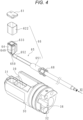
- Fig. 4 is an exploded perspective view of an illumination optical system.
- the illumination optical system includes an illumination unit set 66 and an illumination cover 61.
- the illumination cover 61 is translucent.
- the illumination cover 61 is, for example, a thin flat plate having a thickness of about 0.7 mm.
- An illumination cable 65 is inserted into a cable holding tool 68.
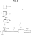
- Fig. 5 is an exploded view of the illumination unit set 66.
- the illumination unit set 66 includes the illumination cable 65, a light-emitting element substrate 63 on which the light-emitting element 633 is mounted, the illumination frame 64, and a second insulating sheet 622.
- Fig. 6 is an explanatory diagram for describing processing for a terminal of the illumination cable 65.
- the illumination cable 65 includes four illumination cable core wires 659. Each of the illumination cable core wires 659 is covered with an insulating coating, and the insulating coating is removed only at the end portion. The insulating coating is colored in a different color for each illumination cable core wire 659.
- a binder (not illustrated) is wrapped around the outer periphery of the four illumination cable core wires 659.
- a shield wire 655 including a large number of metal wires is wrapped around the outside of the binder.
- the metal wire constituting the shield wire 655 is, for example, a copper wire.
- the outer periphery of the shield wire 655 is covered with an outer sheath 656 made of a soft resin.
- the outer sheath 656 is removed to separate the shield wire 655 from the illumination cable core wires 659.
- the separated shield wire 655 is covered with a second tube 652.
- a first tube 651 covers the end portion of the outer sheath 656 and the end portion of the second tube 652.
- the first tube 651 and the second tube 652 are heat shrinkable tubes having insulating properties.
- the shield wire 655 is insulated from the illumination cable core wires 659 and the surroundings at a place other than the end portion of the illumination cable 65.
- the four illumination cable core wires 659 are also insulated from the surroundings at places other than the end portion of the illumination cable 65.
- "insulation" means a state in which electricity is not supplied even when an AC voltage of 500 volts is continuously applied for one minute.
- Fig. 7 is a partial cross-sectional view of Fig. 3 .
- Fig. 7 includes a cross section along line VIIA-VIIA, a cross section along line VIIB-VIIB, and a cross section along line VIIC-VIIC in Fig. 3 .
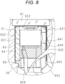
- Fig. 8 is an enlarged view of a region VIII in Fig. 7 .
- the illumination cover 61 is fixed to an illumination hole 31 provided on the side surface of the distal tip member 30 in a watertight and airtight manner.
- the light-emitting element substrate 63 on which the light-emitting element 633 is mounted is disposed at the back of the illumination cover 61.
- the light-emitting element substrate 63 has a square plate shape having a first mounting surface 631 and a second mounting surface 632.
- the light-emitting element substrate 63 has a land such as a copper foil pattern for mounting the light-emitting element 633 on the first mounting surface 631, and has two lands 635 (see Fig. 12 ) on the second mounting surface 632.
- the land for mounting the light-emitting element 633 provided on the first mounting surface 631 and the lands 635 provided on the second mounting surface 632 are connected inside the light-emitting element substrate 63.
- the four illumination cable core wires 659 are twisted two by two, then bent into a substantially L shape as illustrated in Fig. 5 , and mounted on the corresponding lands 635 by soldering or the like.
- the illumination cable core wires 659 function as a power supply wire that supplies power to the light-emitting element 633.
- the shield wire 655 is an example of a conductor wire extending along the power supply wire.
- the light-emitting element substrate 63 is, for example, a multilayer printed substrate.
- the light-emitting element substrate 63 is desirably a high heat dissipation substrate such as: a multilayer printed substrate using a high thermal conductive resin; a ceramic substrate such as an alumina substrate or an aluminum nitride base; or a metal base substrate.
- a first insulating sheet 621 is attached to a side surface of the light-emitting element substrate 63.
- the first insulating sheet 621 is, for example, a polyimide tape. Polyimide has high insulation performance, so that it can ensure sufficient insulation only with a thickness of about several tens of micrometers.
- the first insulating sheet 621 is attached to the left side surface of the light-emitting element substrate 63 without being attached to the right side surface.
- the first insulating sheet 621 may be attached to the entire side surface of the light-emitting element substrate 63.
- the side surface of the light-emitting element substrate 63 is surrounded by the cylindrical illumination frame 64 with the first insulating sheet 621 therebetween.
- the illumination frame 64 has a jig hole 641 which is a circular through hole in a surface on the observation window 27 side.
- One end face of the illumination frame 64 is substantially flush with the upper surface of the light-emitting element 633. That is, the side of the light-emitting element 633 is surrounded by the illumination frame 64.
- the other end face of the illumination frame 64 protrudes downward in Fig. 8 from the second mounting surface 632.
- the second mounting surface 632 and the protruding portion of the illumination frame 64 form a shape of a downward facing box in Fig. 8 .
- the inside of the box is filled with an insulating resin that covers a mounting portion where the illumination cable core wires 659 are mounted on the second mounting surface 632.
- An insulating spacer 69 is disposed between the end portion of the illumination frame 64 and the distal tip member 30.
- the second insulating sheet 622 is attached to the outer peripheral surface of the illumination frame 64.
- the second insulating sheet 622 is, for example, a polyimide tape. Polyimide has high insulation performance, so that it can ensure sufficient insulation only with a thickness of about several tens of micrometers.
- the second insulating sheet 622 covers the outer periphery of the illumination frame 64.
- the second insulating sheet 622 may have a portion attached in multiple layers.
- the second insulating sheet 622 may be formed in a cylindrical shape in advance.
- Fig. 9 is a front view of the distal tip member 30.
- Fig. 10 is a cross-sectional view taken along line X-X in Fig. 9 .
- the distal tip member 30 has an observation hole 39 in the side surface in addition to the above-described illumination hole 31.
- the illumination hole 31 and the observation hole 39 have a substantially rectangular cross section.
- the edges of the illumination hole 31 and an illumination cable hole 32 are stepped in such a manner that the opening side is wider.
- the illumination cable hole 32 communicating with the illumination hole 31 from the end face of the distal tip member 30 on the operation unit side and the observation cable hole 38 communicating with the observation hole 39 are arranged substantially in parallel. As illustrated in Fig. 10 , the illumination hole 31 is narrow in front of a connection portion with the illumination cable hole 32 via a step portion. The connection portion between the illumination hole 31 and the illumination cable hole 32 is obliquely widened.
- the distal tip member 30 is formed of high-strength metal such as stainless steel.
- Fig. 11 is a diagram viewed in a direction of an arrow XI in Fig. 4 .
- the cable holding tool 68 is not illustrated in Fig. 11 .
- the illumination cable 65 has four illumination cable core wires 659, and thus, has a substantially circular cross section. Therefore, it is possible to prevent the application of loads on other incorporated objects due to twisting or the like occurring inside the insertion portion 20.
- the illumination cable 65 is fixed to the illumination cable hole 32 by the cable holding tool 68.
- a large-diameter portion 682 provided at the end portion of the cable holding tool 68 is located outside the illumination cable hole 32 and brought into contact with the distal tip member 30. The details of the structure of the cable holding tool 68 will be described later.
- the shield wire 655 exposed from the distal tip of the second tube 652 is connected to the surface of the illumination frame 64 in a state of being formed flat by soldering or the like as illustrated in Figs. 4 and 11 .
- Fig. 12 is a diagram viewed in a direction of an arrow XII in Fig. 5 .
- the two lands 635 are arranged on the second mounting surface 632.
- the upper land 635 has a shape in which the upper right portion is obliquely cut off. Since the shapes of the two lands 635 are different, the land 635 connected to a positive electrode of the light-emitting element 633 and the land 635 connected to a negative electrode can be easily identified.
- the number of the lands 635 is not limited to two.
- lands 635 for the respective light-emitting elements 633 are provided.
- Fig. 13 is a perspective view of the illumination frame 64.
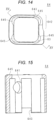
- Fig. 14 is a diagram viewed in a direction of an arrow XIV in Fig. 13 .
- Fig. 15 is a cross-sectional view taken along line XV-XV in Fig. 14 .
- the shape of the illumination frame 64 will be described with reference to Figs. 13 to 15 .
- the illumination frame 64 has a cylindrical shape with a substantially quadrangular cross section.
- the outer shape of the cross section is substantially rectangular, and the inner shape of the cross section is substantially square.
- the left and right walls are thicker than the upper and lower walls.
- the outer surface of the right wall of the illumination frame 64 in Fig. 14 has a stepped shape in which the upper portion is recessed with respect to the lower portion. Therefore, the upper half of the right wall in Fig. 14 is a thin portion 642 having substantially the same thickness as the upper and lower walls. That is, the outer surface of the thin portion 642 is a recess formed along the axial direction of the illumination frame 64.
- the jig hole 641 is provided at the center of the surface on which the thin portion 642 is provided.
- a substantially U-shaped illumination frame groove 643 is provided at a corner in contact with the thin portion 642.
- the thin portion 642 may not be provided over the entire length along the axial direction of the illumination frame 64.
- the thin portion 642 may be formed by a recess contiguous to the end face in a portion on the front side of the jig hole 641 in Fig. 13 , and the upper portion and the lower portion on the inner side from the jig hole 641 may have the same thickness.
- the illumination frame 64 is made of a conductor.
- the illumination frame 64 is desirably made of metal.
- the illumination frame 64 is more desirably made of a copper alloy.
- the illumination frame 64 is still more desirably made of brass.
- the illumination frame 64 may be made of conductive resin or conductive ceramics. In the following, a case where the illumination frame 64 is made of solderable metal will be described as an example.
- the corner of the inner surface is removed in an arc shape from the end face on the side where the illumination frame groove 643 is provided to the middle.
- an abutment portion 645 is provided at an end portion opposite to the side where the illumination frame groove 643 is provided.
- the shield wire 655 is connected to the outside of the thin portion 642 to form a solder connection portion 649. Due to the thin portion 642 being provided, the protrusion of the solder connection portion 649 can be reduced. Therefore, the distal tip member 30 can be downsized.
- the surface of the illumination frame 64 may be subjected to a surface treatment such as tin plating for improving solderability.
- the shield wire 655 covered with the second tube 652 may be folded back to the back surface side of the light-emitting element substrate 63 through the portion of the illumination frame groove 643. Due to the illumination frame groove 643, the shield wire 655 can be shaped such that a surplus portion of the shield wire 655 does not interfere with the illumination hole 31.
- the four illumination cable core wires 659 may be drawn into the illumination frame 64 through the illumination frame groove 643. Since the illumination frame groove 643 is provided, the illumination frame 64 can be reduced in height. Therefore, the distal tip member 30 can be downsized.
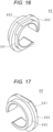
- Figs. 16 and 17 are perspective views of the spacer 69.
- the spacer 69 includes a plate-shaped flange portion 693 having a substantially C shape, a first protrusion 691 protruding from one of both surfaces of the flange portion 693, and a second protrusion 692 protruding from the other surface of the flange portion 693, the first protrusion 691 and the second protrusion 692 having a plate shape with a substantially C shape.
- the inner surfaces of the first protrusion 691, the second protrusion 692, and the flange portion 693 form a smooth arcuate curved surface.
- the first protrusion 691 has flat portions at four positions on the outer surface.
- the spacer 69 has a shape in which the first protrusion 691 is fitted into the end portion of the illumination frame 64 and the flange portion 693 are brought into contact with the end portion of the illumination frame 64.
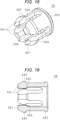
- Fig. 18 is a perspective view of the cable holding tool 68.
- Fig. 19 is a cross-sectional view of the cable holding tool 68.
- the cable holding tool 68 includes an annular large-diameter portion 682 and four cable holding tabs 681 protruding from one surface of the large-diameter portion 682.
- An outer diameter of the large-diameter portion 682 is larger than an inner diameter of the illumination cable hole 32.
- Each of the cable holding tabs 681 has an outer surface protrusion 685 on the outer surface and an inner surface protrusion 686 on the inner surface.
- the end portion of the inner surface protrusion 686 has an obtuse angle.
- the number of the cable holding tabs 681 is not limited to four. Any number equal to or greater than two of cable holding tabs 681 may be provided.
- the outer surface protrusions 685 are pressed by the inner surface of the illumination cable hole 32, so that the four cable holding tabs 681 are deformed inward.
- the inner surface protrusions 686 bite into the outer sheath 656 to firmly hold the illumination cable 65. Since the distal tips of the inner surface protrusions 686 have an obtuse angle, the outer sheath 656 is not broken by the inner surface protrusions 686.
- Figs. 20 and 21 are explanatory diagrams for describing a procedure of assembly of the illumination optical system.
- a person in charge manually assembles the illumination optical system will be described as an example. Different persons in charge may perform the work for each step.
- a part or all of the assembling process may be performed by an automatic assembling device such as an assembling robot.
- the person in charge cuts the illumination cable 65 supplied in the form of a reel roll or the like to a predetermined length (step S501).
- the predetermined length is, for example, slightly longer than the length from the distal tip portion 23 to the connector unit 50 via the operation unit 40 and the universal cord 59.
- the predetermined length may be about the length from the distal tip portion 23 to the operation unit 40.
- step S502 The person in charge inserts the end portion of the cut illumination cable 65 into the cable holding tool 68 (step S502).
- processing on the end portion of the illumination cable 65 on the side the cable holding tabs 681 face will be described.
- the person in charge inserts the end portion of the illumination cable 65 into the first tube 651 (step S503).
- the person in charge inserts the end portion of the illumination cable 65 into the distal tip member 30 through the illumination cable hole 32 and protrudes the end portion of the illumination cable 65 from the illumination hole 31 (step S504).
- the connection portion between the illumination hole 31 and the illumination cable hole 32 is obliquely widened, whereby the person in charge can easily protrude the end portion of the illumination cable 65 from the illumination hole 31.
- the person in charge removes the outer sheath 656 having a predetermined length and the binder (not illustrated) to separate the illumination cable core wires 659 from the shield wire 655 (step S505).
- the predetermined length is about several centimeters.
- the person in charge cuts and removes a filler (not illustrated) at a position as close as possible to the end portion of the outer sheath 656.
- the person in charge twists the shield wires 655 into one wire.
- the person in charge removes the coating of each of the four illumination cable core wires 659 by a predetermined length (step S506).
- the predetermined length is about several millimeters.
- the person in charge twists the portions of the illumination cable core wires 659 from which the coating has been removed two by two.
- the combination of the illumination cable core wires 659 to be twisted is determined by the color of the coating.
- the person in charge forms the twisted illumination cable core wires 659 into a substantially L-shape as illustrated in Fig. 5 , and pre-coats the illumination cable core wires with solder.
- the person in charge connects the two sets of illumination cable core wires 659 to the lands 635 of the light-emitting element substrate 63, respectively (step S507). Which set is connected to which land 635 is determined by the color of the coating. In this manner, the illumination cable core wires 659 are mounted on the lands 635.
- the person in charge attaches the first insulating sheet 621 to the side surface of the light-emitting element substrate 63 (step S508).
- the person in charge may attach the first insulating sheet 621 only when determining that a gap between the light-emitting element substrate 63 and the illumination frame 64 is large after covering the light-emitting element substrate 63 with the illumination frame 64.
- the person in charge may repeat attaching the first insulating sheet 621 and checking the gap with the illumination frame 64 until the light-emitting element substrate 63 is just fitted in the illumination frame 64.
- the person in charge When covering the light-emitting element substrate 63 with the illumination frame 64, the person in charge orients the surface provided with the jig hole 641 in the direction in which the illumination cable core wires 659 are drawn out as illustrated in Fig. 11 .
- the dimension is set such that the light-emitting element substrate 63 is just fit in the illumination frame 64 in a state where the first insulating sheet 621 is wrapped once around the side surface of the light-emitting element substrate 63.
- the dimension may be set such that the light-emitting element substrate 63 is just fit in the illumination frame 64 in a state where the first insulating sheet 621 is not attached.
- the person in charge inserts the light-emitting element substrate 63 inside the illumination frame 64.
- the person in charge temporarily fixes the light-emitting element substrate 63 and the illumination frame 64 in a state where the first mounting surface 631 is brought into contact with the abutment portion 645 (step S509).
- an adhesive that cures in a short time such as a cyanoacrylate adhesive, for example, is used.
- the person in charge may drop the adhesive from the jig hole 641. The dropped adhesive is cured while spreading between the light-emitting element substrate 63 and the inner surface of the illumination frame 64 due to a capillary phenomenon.
- firm adhesion using an epoxy adhesive or the like may be performed.
- the person in charge inserts the twisted shield wires 655 into the second tube 652 cut into a predetermined length.
- the shield wires 655 are exposed several millimeters from the distal tip of the second tube 652.
- the person in charge applies heat to the second tube 652 to contract the second tube 652, thereby fixing the shield wires 655 and the second tube 652 (step S510).
- the person in charge adjusts the position of the first tube 651 so that the first tube 651 covers the end portion of the outer sheath 656 and the end portion of the second tube 652.
- the person in charge applies heat to the first tube 651 to contract the first tube 651, thereby fixing the outer sheath 656, the second tube 652, and the first tube 651 (step S511).
- the solder connection portion 649 includes metal wires forming the shield wire 655 and solder connecting the metal wires to each other. As illustrated in Fig. 11 , it is desirable that the surface of the solder connection portion 649 is formed flat. The person in charge may shape the surface of the solder connection portion 649 using, for example, a file or the like.
- the person in charge attaches the spacer 69 to the illumination frame 64 (step S513). Specifically, the person in charge aligns the directions of the opening of the spacer 69 and the illumination frame groove 643, and with this state, inserts the first protrusion 691 of the spacer 69 into the illumination frame 64. The person in charge pushes the first protrusion 691 until the first protrusion 691 comes in contact with the end face of the illumination frame 64, and temporarily fixes the spacer 69 and the illumination frame 64. For the temporary fixing, an adhesive that cures in a short time such as a cyanoacrylate adhesive, for example, is used.
- the person in charge holds the illumination frame 64 with the spacer 69 facing upward.
- the person in charge injects and cures an insulating resin into a box defined by the second mounting surface 632 and the light-emitting element substrate 63 (step S514).
- the mounting portion where the illumination cable core wires 659 are soldered is protected by the insulating resin.
- the light-emitting element substrate 63, the illumination frame 64, and the spacer 69 are firmly bonded to each other by the insulating resin.
- the person in charge attaches the second insulating sheet 622 to the outer periphery of the illumination frame 64 (step S515). After applying the adhesive to the surface of the second insulating sheet 622, the person in charge inserts the illumination frame 64 into the illumination hole 31 (step S516). After wiping off the excess adhesive, the person in charge cures the adhesive under predetermined curing conditions.
- the person in charge pushes and fixes the cable holding tool 68 into the illumination cable hole 32 (step S517).
- the cable holding tool 68 is fixed inside the illumination cable hole 32 by elasticity.
- a recess for holding the tabs of the cable holding tool 68 may be provided on the inner surface of the illumination cable hole 32.
- the person in charge may adhesively fix the cable holding tool 68 and the illumination cable hole 32.
- the person in charge adhesively fixes the illumination cover 61 to the end portion of the illumination hole 31 (step S518). At this time, the person in charge sufficiently spreads the adhesive between the edge of the illumination cover 61 and the inner surface of the illumination hole 31 to bond the illumination cover 61 and the illumination hole 31 in a watertight manner. In this manner, the illumination optical system fixed to the distal tip member 30 is completed.
- the other end side of the illumination cable 65 is connected to the electrical connector 51 of the connector unit 50.
- the illumination cable 65 may be connected to the electrical connector 51 via another cable connected inside the operation unit 40.
- the shield wire 655 is connected to a signal ground (GND) of the endoscope processor, that is, a GND of a patient circuit, via the electrical connector 51.
- GND signal ground
- the distal tip member 30 is electrically connected to a metal member provided in the operation unit 40 and the connector unit 50 via a bending mechanism inside the bending section 22 and a metal member in the flexible tube constituting the exterior of the soft portion 21.
- These metal members are capacitively connected to a housing of the endoscope processor, that is, a frame GND, via a capacitor provided inside the connector unit 50 or the like. Since a structure for connecting a metal member constituting the endoscope 10 to the frame GND is conventionally used, the detailed description thereof will be omitted.
- the shield wire 655 and the light-emitting element 633 are insulated by the first insulating sheet 621, the insulating resin covering the connection portion between the illumination cable core wires 659 and the light-emitting element substrate 63, the second tube 652, the coating of the illumination cable core wires 659, and the like.
- the shield wire 655 is insulated from the metal portion constituting the distal tip member 30 and the endoscope 10 by the second insulating sheet 622, the second tube 652, the outer sheath 656, and the like.
- the GND side is connected to a GND potential or the like of the patient circuit via the electrical connector 51.
- the light-emitting element 633 and the metal member constituting the endoscope 10 are insulated by the insulating resin covering the connection portion between the illumination cable core wires 659 and the light-emitting element substrate 63, the spacer 69, the coating of the illumination cable core wires 659, and the like.
- the light-emitting element 633, the metal member constituting the endoscope 10, and the shield wire 655 are insulated from each other in a portion other than the connector unit 50. With such an insulating structure, electrical safety required for medical electric equipment is ensured.
- the outline of the usage of the endoscope 10 into which the illumination optical system is incorporated according to the embodiment will be described.
- Power is supplied from the endoscope processor to the light-emitting element 633 via the illumination cable 65.
- the light-emitting element 633 emits light with luminance corresponding to the supplied current of the power supply to emit light in the viewing direction of the observation window 27.
- the emission luminance of the light-emitting element 633 is adjusted by, for example, an automatic dimming function of the endoscope processor.
- the emission luminance may be adjusted on the basis of an operation of a user such as a doctor.
- a patient, a doctor, an instrument disposed around the distal tip portion 23 of the endoscope 10, or the like may be charged by static electricity, and may cause discharge with the distal tip portion 23. If a current due to the discharge passes through the light-emitting element 633, the light-emitting element 633 may be damaged.
- the light-emitting element 633 is surrounded by the illumination frame 64 which is a conductor except for the light-emitting surface.
- a conductive path connected from the illumination frame 64 to the connector unit 50 via the shield wire 655 serves as a lightning rod, whereby it is possible to reduce the possibility that the light-emitting element 633 is damaged by the current due to the discharge.
- Heat generated in the light-emitting element 633 will be described.
- a sheet having a thickness of about several tens of micrometers is used as the first insulating sheet 621 and the second insulating sheet 622, heat generated in the light-emitting element 633 passes through these sheets by thermal conduction and reaches the illumination frame 64.
- the heat generated in the light-emitting element 633 is diffused into the insertion portion 20 while being conducted to the operation unit side via both the illumination cable core wires 659 and the shield wire 655. That is, the shield wire 655 functions as a heat conduction wire.
- the illumination frame 64 and the shield wire 655 also serve as a heat dissipation path that dissipates heat generated by the light-emitting element 633.
- An increase in temperature of the light-emitting element 633 can be reduced by both heat dissipation paths.
- the present embodiment can provide the endoscope 10 which is hardly damaged by static electricity.
- the present embodiment can provide the endoscope 10 capable of preventing an increase in temperature of the light-emitting element 633.
- the illumination cable core wires 659 are twisted two by two at the distal tip, and thus, the endoscope 10 can be provided that does not interfere with an endoscopic examination even if one illumination cable core wire 659 is broken.
- a reduction in diameter and a reduction in distal rigid length can be achieved in, for example, the endoscope 10 having a complicated structure in the distal tip portion 23 such as a duodenum endoscope having a forceps elevating function.
- a method of connecting the shield wire 655 and the illumination frame 64 is not limited to soldering.
- the shield wire 655 and the illumination frame 64 may be connected by, for example, brazing, ultrasonic welding, or a conductive adhesive.
- the endoscope 10 is not limited to the side-viewing type.
- the endoscope 10 may be a so-called direct-viewing type provided with the observation window 27 and the illumination window 60 on an end face of the distal tip portion 23.
- the endoscope 10 may be of a so-called oblique-viewing type including the observation window 27 and the illumination window 60 that are obliquely provided with respect to the insertion direction.
- Fig. 22 is an explanatory diagram for describing a modification of a step of fixing the illumination frame 64 and the light-emitting element substrate 63.
- the step illustrated in Fig. 22 is a modification of step S509 described with reference to Fig. 20 .
- the person in charge applies a small amount of adhesive to the surface of the inner surface of the illumination frame 64 opposite to the surface provided with the jig hole 641, and then inserts the light-emitting element substrate 63 into the illumination frame 64.
- the person in charge may apply a small amount of adhesive to the side surface of the light-emitting element substrate 63 instead of the inner surface of the illumination frame 64.
- the person in charge After bringing the first mounting surface 631 into contact with the abutment portion 645, the person in charge inserts a cylindrical jig 18 into the jig hole 641 as illustrated in Fig. 22 to press the light-emitting element substrate 63, thereby pressing the light-emitting element substrate against the inner surface of the illumination frame 64. The person in charge cures the adhesive while continuing pressing.
- the jig 18 is not limited to have a cylindrical shape.
- the jig 18 may include a mechanism for pressing the illumination frame 64.
- the jig 18 may include a mechanism that sets the pressing force to an appropriate strength.
- the endoscope 10 that prevents a variation in the direction of the illumination light emitted from the light-emitting element 633 due to a deviation in the positional relationship between the light-emitting element substrate 63 and the illumination frame 64 at the time of temporary fixing.
- the present modification relates to an endoscope 10 in which the illumination cable 65 does not include the shield wire 655.
- the descriptions of portions common to those of the first embodiment will be omitted.
- the illumination cable 65 includes one conductor wire in addition to the four illumination cable core wires 659 described with reference to Fig. 6 .
- the conductor wire is covered with an insulating coating.
- a binder is wrapped around the outer periphery of the four illumination cable core wires 659 and the conductor wire.
- the binder is covered with an outer sheath 656 made of a soft resin.
- the outer sheath 656 is removed to separate the conductor wire from the illumination cable core wires 659.
- the insulating coating at the distal tip of the conductor wire is removed, and the conductor wire is connected to the illumination frame 64.
- the step of attaching the second tube 652 and the first tube 651 can be eliminated.
- the conductor wire may not be covered with the insulating coating. In such a case, it is desirable to attach the second tube 652 and the first tube 651 after removal of the outer sheath 656 to insulate portions other than a portion connected to the illumination frame 64.
- Fig. 23 is an exploded view of an illumination unit set 66 in the second embodiment.
- Figs. 24 and 25 are perspective views of a light-emitting element substrate 63 according to the second embodiment.
- the light-emitting element substrate 63 includes a connection pin 636 protruding from the second mounting surface 632 instead of the land 635 in the first embodiment.
- the number of the connection pins 636 may be the same as the number of the illumination cable core wires 659, or may be two like the lands 635.
- the light-emitting element substrate 63 includes an illumination frame connection portion 638 on a side surface.
- the illumination frame connection portion 638 is a solderable land, and is insulated from the connection pin 636 by an insulating material constituting the light-emitting element substrate 63.
- the side surface not having the illumination frame connection portion 638 is also insulated from a wiring material inside the light-emitting element substrate 63.
- the light-emitting element substrate 63 has an element recess 634 recessed in a substantially square shape in the first mounting surface 631.
- the element recess 634 is slightly larger in dimension than the light-emitting element 633.
- a land on which the light-emitting element 633 is mounted is disposed at the bottom of the element recess 634.
- the light-emitting element substrate 63 is supplied in a state where the light-emitting element 633 is mounted in the element recess 634.
- the number of the mounted light-emitting elements 633 may be one or more
- the light-emitting element substrate 63 may include a light-emitting element 633 that does not include a phosphor converting an emission wavelength, and a phosphor that is filled in the element recess 634 and covers the light-emitting element 633.
- the light-emitting element substrate 63 described above is manufactured by filling and curing a resin containing a phosphor after the light-emitting element 633 is mounted on the first mounting surface 631. Since the light-emitting element substrate 63 is sealed with the resin containing the phosphor, the light-emitting element substrate 63 having high durability can be achieved.
- step S507 described with reference to Fig. 20 the person in charge pre-coats the portion of the illumination cable core wires 659 from which the coating has been removed with solder, then places the portion along the connection pin 636, and performs soldering.
- the worker may insert the illumination cable core wires 659 into a heat shrinkable tube and cover the soldered portion with the heat shrinkable tube.
- the first insulating sheet 621 is not used. That is, step S508 described with reference to Fig. 20 is unnecessary.
- step S509 described with reference to Fig. 20 the person in charge pre-coats the illumination frame connection portion 638 with solder.
- the person in charge inserts the light-emitting element substrate 63 inside the illumination frame 64.
- the person in charge applies a soldering iron to the illumination frame 64 in a state where the first mounting surface 631 is brought into contact with the abutment portion 645 to thereby melt the solder pre-coated on the illumination frame connection portion 638.
- the temporary fixing between the illumination frame 64 and the light-emitting element substrate 63 is completed.
- the first insulating sheet 621 is not used, whereby inclination between the light-emitting element substrate 63 and the illumination frame 64 due to wrinkles or the like of the first insulating sheet 621 can be prevented. Therefore, the endoscope 10 can be provided that prevents a variation in the direction of the illumination light emitted from the light-emitting element 633.
- the present embodiment it is possible to easily fix the illumination frame 64 and the light-emitting element substrate 63.
- the worker can remove the illumination frame 64 and the light-emitting element substrate 63 as necessary by applying a soldering iron to the illumination frame 64.
- the illumination frame 64 and the light-emitting element substrate 63 are closely bonded to each other by solder having high thermal conductivity. Therefore, heat generated by the light-emitting element 633 is more easily transferred to the illumination frame 64 than in the case of using the first insulating sheet 621. As described above, an increase in temperature of the light-emitting element 633 can be further reduced as compared with the first embodiment.
- the present embodiment relates to an endoscope 10 in which a part of a wall surface of an illumination frame 64 is constituted by a shield wire 655.
- a shield wire 655. The descriptions of portions common to those of the first embodiment will be omitted.
- Fig. 26 is an explanatory diagram for describing the configuration of an illumination unit set 66 according to the third embodiment.
- Fig. 26 is a diagram of the illumination unit set 66 before the second insulating sheet 622 is attached as viewed in the same direction as in Fig. 11 .
- the cable holding tool 68 is not illustrated in Fig. 26 .
- Fig. 27 is a perspective view of an illumination frame 64 according to the third embodiment.
- Fig. 27 is a perspective view as viewed in the same direction as in Fig. 13 , and the abutment portion 645 described with reference to Fig. 14 is provided on the back side.
- the illumination frame 64 is provided with a connection groove 648 that opens to the side where the abutment portion 645 is not provided.
- connection groove 648 penetrates the cylindrical portion of the illumination frame 64 in the thickness direction, and has a substantially U shape when the illumination frame 64 is viewed from the outside.
- the side surface of the connection groove 648 connects the inner surface and the outer surface of the illumination frame 64.
- a distal tip portion of the shield wire 655 is soldered to the illumination frame 64 while being inserted into the connection groove 648.
- the surface of the solder connection portion 649 is substantially flush with the outer surface of the illumination frame 64, and the back surface of the solder connection portion 649 is substantially flush with the inner surface of the illumination frame 64. That is, the shield wire 655 and the solder for fixing the shield wire 655 integrally fill the connection groove 648 to form a wall surface of the illumination frame 64.
- the outer surface of the solder connection portion 649 may be processed to be substantially flush with the outer surface of the illumination frame 64 by, for example, polishing or sanding after completion of soldering.
- the solder connection portion 649 can be prevented from protruding from the illumination frame 64.
- the endoscope 10 can be provided in which the light-emitting element 633 is less susceptible to static electricity due to external noise or the like.
- An endoscope including:
Landscapes
- Health & Medical Sciences (AREA)
- Life Sciences & Earth Sciences (AREA)
- Physics & Mathematics (AREA)
- Surgery (AREA)
- Optics & Photonics (AREA)
- Engineering & Computer Science (AREA)
- Biomedical Technology (AREA)
- Animal Behavior & Ethology (AREA)
- Pathology (AREA)
- Radiology & Medical Imaging (AREA)
- Veterinary Medicine (AREA)
- Biophysics (AREA)
- Public Health (AREA)
- Heart & Thoracic Surgery (AREA)
- Medical Informatics (AREA)
- Molecular Biology (AREA)
- Nuclear Medicine, Radiotherapy & Molecular Imaging (AREA)
- General Health & Medical Sciences (AREA)
- General Physics & Mathematics (AREA)
- Astronomy & Astrophysics (AREA)
- Microelectronics & Electronic Packaging (AREA)
- Endoscopes (AREA)
Abstract
Description
- The present invention relates to an endoscope.
- An endoscope including a light-emitting element that is disposed at a distal tip of an insertion portion has been proposed (Patent Literature 1).
- Patent Literature 1:
WO 2013/061838 A - A light-emitting element which is a semiconductor product may be damaged by static electricity. In one aspect, an object is to provide an endoscope that is not susceptible to damage due to static electricity.
- An endoscope includes: an observation window fixed to a distal tip member disposed at a distal tip of an insertion portion; and an illumination unit that emits light in a viewing direction of the observation window, the illumination unit including a light-emitting element, a power supply wire that supplies power to the light-emitting element, a conductor wire extending along the power supply wire, and an illumination frame that is conductive, surrounds a connection portion between the light-emitting element and the power supply wire, is insulated from the power supply wire, and is electrically connected to the conductor wire.
- According to one aspect, an endoscope that is less susceptible to damage due to static electricity can be provided.
-
-
Fig. 1 is an exterior view of an endoscope. -
Fig. 2 is an enlarged view of a region II inFig. 1 . -
Fig. 3 is an enlarged view of an insertion portion from which an endoscope cap is removed. -
Fig. 4 is an exploded perspective view of an illumination optical system. -
Fig. 5 is an exploded view of an illumination unit set. -
Fig. 6 is an explanatory diagram for describing processing of an illumination cable. -
Fig. 7 is a partial cross-sectional view ofFig. 3 . -
Fig. 8 is an enlarged view of a region VIII inFig. 7 . -
Fig. 9 is a front view of a distal tip member. -
Fig. 10 is a cross-sectional view taken along line X-X inFig. 9 . -
Fig. 11 is a diagram viewed in a direction of an arrow XI inFig. 4 . -
Fig. 12 is a diagram viewed in a direction of an arrow XII inFig. 5 . -
Fig. 13 is a perspective view of an illumination frame. -
Fig. 14 is a diagram viewed in a direction of an arrow XIV inFig. 13 . -
Fig. 15 is a cross-sectional view taken along line XV-XV inFig. 14 . -
Fig. 16 is a perspective view of a spacer. -
Fig. 17 is a perspective view of the spacer. -
Fig. 18 is a perspective view of a cable holding tool. -
Fig. 19 is a cross-sectional view of the cable holding tool. -
Fig. 20 is an explanatory diagram for describing a procedure of assembly of the illumination optical system. -
Fig. 21 is an explanatory diagram for describing the procedure of assembly of the illumination optical system. -
Fig. 22 is an explanatory diagram for describing a modification of a step of fixing the illumination frame and a light-emitting element substrate. -
Fig. 23 is an exploded view of an illumination unit set according to a second embodiment. -
Fig. 24 is a perspective view of a light-emitting element substrate according to the second embodiment. -
Fig. 25 is a perspective view of the light-emitting element substrate according to the second embodiment. -
Fig. 26 is an explanatory diagram of an illumination unit set according to a third embodiment. -
Fig. 27 is a perspective view of an illumination frame according to the third embodiment. -
Fig. 1 is an exterior view of anendoscope 10. Theendoscope 10 according to the present embodiment is a flexible scope for duodenum. Theendoscope 10 includes aninsertion portion 20, anoperation unit 40, auniversal cord 59, and aconnector unit 50. Theoperation unit 40 has abending knob 41 and achannel inlet 42. - The
insertion portion 20 is long and has one end connected to theoperation unit 40 via abend preventing portion 26. Theinsertion portion 20 includes asoft portion 21, abending section 22, and adistal tip portion 23 in the order from theoperation unit 40 side. Thebending section 22 bends in accordance with the operation of thebending knob 41. - A channel penetrating the
insertion portion 20 is provided from thechannel inlet 42 to thedistal tip portion 23. Aforceps plug 43 is fixed to thechannel inlet 42, theforceps plug 43 having an insertion port through which a treatment instrument or the like is inserted. - In the following description, a longitudinal direction of the
insertion portion 20 is referred to as an insertion direction. Similarly, a side close to theoperation unit 40 along the insertion direction is referred to as an operation unit side, and a side far from theoperation unit 40 is referred to as a distal side. - The
universal cord 59 is long, and has a first end connected to theoperation unit 40 and a second end connected to theconnector unit 50. Theconnector unit 50 includes anelectrical connector 51. Theelectrical connector 51 is connected to an endoscope processor (not illustrated). -
Fig. 2 is an enlarged view of a region II inFig. 1 . As illustrated inFig. 2 , anillumination window 60 and anobservation window 27 are arranged on a side surface of thedistal tip portion 23. Theendoscope 10 according to the present embodiment is what is called a side-viewing endoscope in which the viewing direction of theobservation window 27 is substantially perpendicular to the insertion direction. Anelevator 25 is disposed beside theillumination window 60 and theobservation window 27. Anendoscope cap 24 that is detachable together with theelevator 25 is attached to the distal tip of theinsertion portion 20. -
Fig. 3 is an enlarged view of theinsertion portion 20 from which theendoscope cap 24 is removed. InFig. 3 , components and the like constituting thebending section 22 are not illustrated, and only main components constituting thedistal tip portion 23 are illustrated. - The
observation window 27 and theillumination window 60 are fixed to a substantially cylindricaldistal tip member 30. Theillumination window 60 is located distal to theobservation window 27 along the insertion direction. InFig. 3 , theelevator 25 disposed above theillumination window 60 and theobservation window 27 is detached from theinsertion portion 20 together with theendoscope cap 24. -
Fig. 4 is an exploded perspective view of an illumination optical system. InFig. 4 , components other than the illumination optical system are not illustrated. The illumination optical system includes an illumination unit set 66 and anillumination cover 61. Theillumination cover 61 is translucent. Theillumination cover 61 is, for example, a thin flat plate having a thickness of about 0.7 mm. Anillumination cable 65 is inserted into acable holding tool 68. -
Fig. 5 is an exploded view of the illumination unit set 66. The illumination unit set 66 includes theillumination cable 65, a light-emittingelement substrate 63 on which the light-emittingelement 633 is mounted, theillumination frame 64, and a second insulatingsheet 622. -
Fig. 6 is an explanatory diagram for describing processing for a terminal of theillumination cable 65. Theillumination cable 65 includes four illuminationcable core wires 659. Each of the illuminationcable core wires 659 is covered with an insulating coating, and the insulating coating is removed only at the end portion. The insulating coating is colored in a different color for each illuminationcable core wire 659. - A binder (not illustrated) is wrapped around the outer periphery of the four illumination
cable core wires 659. Ashield wire 655 including a large number of metal wires is wrapped around the outside of the binder. The metal wire constituting theshield wire 655 is, for example, a copper wire. The outer periphery of theshield wire 655 is covered with anouter sheath 656 made of a soft resin. - At the end portion of the
illumination cable 65, theouter sheath 656 is removed to separate theshield wire 655 from the illuminationcable core wires 659. The separatedshield wire 655 is covered with asecond tube 652. Afirst tube 651 covers the end portion of theouter sheath 656 and the end portion of thesecond tube 652. - In the present embodiment, the
first tube 651 and thesecond tube 652 are heat shrinkable tubes having insulating properties. As described above, theshield wire 655 is insulated from the illuminationcable core wires 659 and the surroundings at a place other than the end portion of theillumination cable 65. The four illuminationcable core wires 659 are also insulated from the surroundings at places other than the end portion of theillumination cable 65. In the present embodiment, "insulation" means a state in which electricity is not supplied even when an AC voltage of 500 volts is continuously applied for one minute. -
Fig. 7 is a partial cross-sectional view ofFig. 3 .Fig. 7 includes a cross section along line VIIA-VIIA, a cross section along line VIIB-VIIB, and a cross section along line VIIC-VIIC inFig. 3 .Fig. 8 is an enlarged view of a region VIII inFig. 7 . - A portion appearing in the cross section along line VIIA-VIIA will be described with reference to
Figs. 7 and8 . Theillumination cover 61 is fixed to anillumination hole 31 provided on the side surface of thedistal tip member 30 in a watertight and airtight manner. The light-emittingelement substrate 63 on which the light-emittingelement 633 is mounted is disposed at the back of theillumination cover 61. - The light-emitting
element substrate 63 has a square plate shape having a first mountingsurface 631 and asecond mounting surface 632. The light-emittingelement substrate 63 has a land such as a copper foil pattern for mounting the light-emittingelement 633 on the first mountingsurface 631, and has two lands 635 (seeFig. 12 ) on the second mountingsurface 632. The land for mounting the light-emittingelement 633 provided on the first mountingsurface 631 and thelands 635 provided on the second mountingsurface 632 are connected inside the light-emittingelement substrate 63. - The four illumination
cable core wires 659 are twisted two by two, then bent into a substantially L shape as illustrated inFig. 5 , and mounted on the correspondinglands 635 by soldering or the like. The illuminationcable core wires 659 function as a power supply wire that supplies power to the light-emittingelement 633. Theshield wire 655 is an example of a conductor wire extending along the power supply wire. - The light-emitting
element substrate 63 is, for example, a multilayer printed substrate. The light-emittingelement substrate 63 is desirably a high heat dissipation substrate such as: a multilayer printed substrate using a high thermal conductive resin; a ceramic substrate such as an alumina substrate or an aluminum nitride base; or a metal base substrate. - A first insulating
sheet 621 is attached to a side surface of the light-emittingelement substrate 63. The first insulatingsheet 621 is, for example, a polyimide tape. Polyimide has high insulation performance, so that it can ensure sufficient insulation only with a thickness of about several tens of micrometers. InFig. 8 , the first insulatingsheet 621 is attached to the left side surface of the light-emittingelement substrate 63 without being attached to the right side surface. The first insulatingsheet 621 may be attached to the entire side surface of the light-emittingelement substrate 63. - The side surface of the light-emitting
element substrate 63 is surrounded by thecylindrical illumination frame 64 with the first insulatingsheet 621 therebetween. Theillumination frame 64 has ajig hole 641 which is a circular through hole in a surface on theobservation window 27 side. One end face of theillumination frame 64 is substantially flush with the upper surface of the light-emittingelement 633. That is, the side of the light-emittingelement 633 is surrounded by theillumination frame 64. The other end face of theillumination frame 64 protrudes downward inFig. 8 from the second mountingsurface 632. - The
second mounting surface 632 and the protruding portion of theillumination frame 64 form a shape of a downward facing box inFig. 8 . The inside of the box is filled with an insulating resin that covers a mounting portion where the illuminationcable core wires 659 are mounted on the second mountingsurface 632. - An insulating
spacer 69 is disposed between the end portion of theillumination frame 64 and thedistal tip member 30. The secondinsulating sheet 622 is attached to the outer peripheral surface of theillumination frame 64. The secondinsulating sheet 622 is, for example, a polyimide tape. Polyimide has high insulation performance, so that it can ensure sufficient insulation only with a thickness of about several tens of micrometers. The secondinsulating sheet 622 covers the outer periphery of theillumination frame 64. The secondinsulating sheet 622 may have a portion attached in multiple layers. The secondinsulating sheet 622 may be formed in a cylindrical shape in advance. -
Fig. 9 is a front view of thedistal tip member 30.Fig. 10 is a cross-sectional view taken along line X-X inFig. 9 . Thedistal tip member 30 has anobservation hole 39 in the side surface in addition to the above-describedillumination hole 31. Theillumination hole 31 and theobservation hole 39 have a substantially rectangular cross section. The edges of theillumination hole 31 and anillumination cable hole 32 are stepped in such a manner that the opening side is wider. - The
illumination cable hole 32 communicating with theillumination hole 31 from the end face of thedistal tip member 30 on the operation unit side and theobservation cable hole 38 communicating with theobservation hole 39 are arranged substantially in parallel. As illustrated inFig. 10 , theillumination hole 31 is narrow in front of a connection portion with theillumination cable hole 32 via a step portion. The connection portion between theillumination hole 31 and theillumination cable hole 32 is obliquely widened. Thedistal tip member 30 is formed of high-strength metal such as stainless steel. -
Fig. 11 is a diagram viewed in a direction of an arrow XI inFig. 4 . Thecable holding tool 68 is not illustrated inFig. 11 . Theillumination cable 65 has four illuminationcable core wires 659, and thus, has a substantially circular cross section. Therefore, it is possible to prevent the application of loads on other incorporated objects due to twisting or the like occurring inside theinsertion portion 20. - Returning to
Fig. 7 , the description will be continued. A portion appearing in the cross section along line VIIB-VIIB inFig. 3 will be described. As described above, theillumination cable 65 is fixed to theillumination cable hole 32 by thecable holding tool 68. A large-diameter portion 682 provided at the end portion of thecable holding tool 68 is located outside theillumination cable hole 32 and brought into contact with thedistal tip member 30. The details of the structure of thecable holding tool 68 will be described later. - A portion appearing in the cross section along line VIIC-VIIC in
Figs. 7 and8 will be described. Theshield wire 655 exposed from the distal tip of thesecond tube 652 is connected to the surface of theillumination frame 64 in a state of being formed flat by soldering or the like as illustrated inFigs. 4 and11 . -
Fig. 12 is a diagram viewed in a direction of an arrow XII inFig. 5 . As described above, the twolands 635 are arranged on the second mountingsurface 632. Theupper land 635 has a shape in which the upper right portion is obliquely cut off. Since the shapes of the twolands 635 are different, theland 635 connected to a positive electrode of the light-emittingelement 633 and theland 635 connected to a negative electrode can be easily identified. - The number of the
lands 635 is not limited to two. For example, when two types of light-emittingelements 633 for white light and narrowband light are mounted on the first mountingsurface 631, lands 635 for the respective light-emittingelements 633 are provided. -
Fig. 13 is a perspective view of theillumination frame 64.Fig. 14 is a diagram viewed in a direction of an arrow XIV inFig. 13 .Fig. 15 is a cross-sectional view taken along line XV-XV inFig. 14 . The shape of theillumination frame 64 will be described with reference toFigs. 13 to 15 . - The
illumination frame 64 has a cylindrical shape with a substantially quadrangular cross section. The outer shape of the cross section is substantially rectangular, and the inner shape of the cross section is substantially square. InFig. 14 , the left and right walls are thicker than the upper and lower walls. The outer surface of the right wall of theillumination frame 64 inFig. 14 has a stepped shape in which the upper portion is recessed with respect to the lower portion. Therefore, the upper half of the right wall inFig. 14 is athin portion 642 having substantially the same thickness as the upper and lower walls. That is, the outer surface of thethin portion 642 is a recess formed along the axial direction of theillumination frame 64. Thejig hole 641 is provided at the center of the surface on which thethin portion 642 is provided. A substantially U-shapedillumination frame groove 643 is provided at a corner in contact with thethin portion 642. - Note that the
thin portion 642 may not be provided over the entire length along the axial direction of theillumination frame 64. For example, thethin portion 642 may be formed by a recess contiguous to the end face in a portion on the front side of thejig hole 641 inFig. 13 , and the upper portion and the lower portion on the inner side from thejig hole 641 may have the same thickness. - The
illumination frame 64 is made of a conductor. Theillumination frame 64 is desirably made of metal. Theillumination frame 64 is more desirably made of a copper alloy. Theillumination frame 64 is still more desirably made of brass. Theillumination frame 64 may be made of conductive resin or conductive ceramics. In the following, a case where theillumination frame 64 is made of solderable metal will be described as an example. - As illustrated in
Fig. 14 , the corner of the inner surface is removed in an arc shape from the end face on the side where theillumination frame groove 643 is provided to the middle. As illustrated inFig. 15 , anabutment portion 645 is provided at an end portion opposite to the side where theillumination frame groove 643 is provided. When the light-emittingelement substrate 63 is inserted from the side where theillumination frame groove 643 is provided, the edge of the light-emittingelement substrate 63 is brought into contact with theabutment portion 645 as indicated by a dash-dot-dot-dash line inFig. 14 . - As illustrated in
Fig. 11 , theshield wire 655 is connected to the outside of thethin portion 642 to form asolder connection portion 649. Due to thethin portion 642 being provided, the protrusion of thesolder connection portion 649 can be reduced. Therefore, thedistal tip member 30 can be downsized. When theshield wire 655 is connected to theillumination frame 64 by soldering, the surface of theillumination frame 64 may be subjected to a surface treatment such as tin plating for improving solderability. - Before soldering or after soldering, the
shield wire 655 covered with thesecond tube 652 may be folded back to the back surface side of the light-emittingelement substrate 63 through the portion of theillumination frame groove 643. Due to theillumination frame groove 643, theshield wire 655 can be shaped such that a surplus portion of theshield wire 655 does not interfere with theillumination hole 31. - The four illumination
cable core wires 659 may be drawn into theillumination frame 64 through theillumination frame groove 643. Since theillumination frame groove 643 is provided, theillumination frame 64 can be reduced in height. Therefore, thedistal tip member 30 can be downsized. -
Figs. 16 and 17 are perspective views of thespacer 69. Thespacer 69 includes a plate-shapedflange portion 693 having a substantially C shape, afirst protrusion 691 protruding from one of both surfaces of theflange portion 693, and asecond protrusion 692 protruding from the other surface of theflange portion 693, thefirst protrusion 691 and thesecond protrusion 692 having a plate shape with a substantially C shape. - The inner surfaces of the
first protrusion 691, thesecond protrusion 692, and theflange portion 693 form a smooth arcuate curved surface. Thefirst protrusion 691 has flat portions at four positions on the outer surface. As illustrated inFig. 8 , thespacer 69 has a shape in which thefirst protrusion 691 is fitted into the end portion of theillumination frame 64 and theflange portion 693 are brought into contact with the end portion of theillumination frame 64. -
Fig. 18 is a perspective view of thecable holding tool 68.Fig. 19 is a cross-sectional view of thecable holding tool 68. Thecable holding tool 68 includes an annular large-diameter portion 682 and fourcable holding tabs 681 protruding from one surface of the large-diameter portion 682. An outer diameter of the large-diameter portion 682 is larger than an inner diameter of theillumination cable hole 32. Each of thecable holding tabs 681 has anouter surface protrusion 685 on the outer surface and aninner surface protrusion 686 on the inner surface. The end portion of theinner surface protrusion 686 has an obtuse angle. - Note that the number of the
cable holding tabs 681 is not limited to four. Any number equal to or greater than two ofcable holding tabs 681 may be provided. - Returning back to
Fig. 7 , the description of the cross section along VIIB-VIIB will be continued. Although not illustrated inFig. 7 , theouter surface protrusions 685 are pressed by the inner surface of theillumination cable hole 32, so that the fourcable holding tabs 681 are deformed inward. Theinner surface protrusions 686 bite into theouter sheath 656 to firmly hold theillumination cable 65. Since the distal tips of theinner surface protrusions 686 have an obtuse angle, theouter sheath 656 is not broken by theinner surface protrusions 686. -
Figs. 20 and21 are explanatory diagrams for describing a procedure of assembly of the illumination optical system. In the following description, a case where a person in charge manually assembles the illumination optical system will be described as an example. Different persons in charge may perform the work for each step. A part or all of the assembling process may be performed by an automatic assembling device such as an assembling robot. - The person in charge cuts the
illumination cable 65 supplied in the form of a reel roll or the like to a predetermined length (step S501). The predetermined length is, for example, slightly longer than the length from thedistal tip portion 23 to theconnector unit 50 via theoperation unit 40 and theuniversal cord 59. The predetermined length may be about the length from thedistal tip portion 23 to theoperation unit 40. - The person in charge inserts the end portion of the
cut illumination cable 65 into the cable holding tool 68 (step S502). In the following description, processing on the end portion of theillumination cable 65 on the side thecable holding tabs 681 face will be described. - The person in charge inserts the end portion of the
illumination cable 65 into the first tube 651 (step S503). The person in charge inserts the end portion of theillumination cable 65 into thedistal tip member 30 through theillumination cable hole 32 and protrudes the end portion of theillumination cable 65 from the illumination hole 31 (step S504). As described above, the connection portion between theillumination hole 31 and theillumination cable hole 32 is obliquely widened, whereby the person in charge can easily protrude the end portion of theillumination cable 65 from theillumination hole 31. - The person in charge removes the
outer sheath 656 having a predetermined length and the binder (not illustrated) to separate the illuminationcable core wires 659 from the shield wire 655 (step S505). The predetermined length is about several centimeters. The person in charge cuts and removes a filler (not illustrated) at a position as close as possible to the end portion of theouter sheath 656. The person in charge twists theshield wires 655 into one wire. - The person in charge removes the coating of each of the four illumination
cable core wires 659 by a predetermined length (step S506). The predetermined length is about several millimeters. The person in charge twists the portions of the illuminationcable core wires 659 from which the coating has been removed two by two. The combination of the illuminationcable core wires 659 to be twisted is determined by the color of the coating. - The person in charge forms the twisted illumination
cable core wires 659 into a substantially L-shape as illustrated inFig. 5 , and pre-coats the illumination cable core wires with solder. The person in charge connects the two sets of illuminationcable core wires 659 to thelands 635 of the light-emittingelement substrate 63, respectively (step S507). Which set is connected to whichland 635 is determined by the color of the coating. In this manner, the illuminationcable core wires 659 are mounted on thelands 635. - The person in charge attaches the first insulating
sheet 621 to the side surface of the light-emitting element substrate 63 (step S508). The person in charge may attach the first insulatingsheet 621 only when determining that a gap between the light-emittingelement substrate 63 and theillumination frame 64 is large after covering the light-emittingelement substrate 63 with theillumination frame 64. The person in charge may repeat attaching the first insulatingsheet 621 and checking the gap with theillumination frame 64 until the light-emittingelement substrate 63 is just fitted in theillumination frame 64. - When covering the light-emitting
element substrate 63 with theillumination frame 64, the person in charge orients the surface provided with thejig hole 641 in the direction in which the illuminationcable core wires 659 are drawn out as illustrated inFig. 11 . - In a case where the light-emitting
element substrate 63 and theillumination frame 64 can be manufactured with high accuracy, it is desirable that the dimension is set such that the light-emittingelement substrate 63 is just fit in theillumination frame 64 in a state where the first insulatingsheet 621 is wrapped once around the side surface of the light-emittingelement substrate 63. In a case where the distance between the side surface of the light-emittingelement substrate 63 and the internal electrode of the light-emittingelement substrate 63 can be sufficiently ensured, the dimension may be set such that the light-emittingelement substrate 63 is just fit in theillumination frame 64 in a state where the first insulatingsheet 621 is not attached. - The person in charge inserts the light-emitting
element substrate 63 inside theillumination frame 64. The person in charge temporarily fixes the light-emittingelement substrate 63 and theillumination frame 64 in a state where the first mountingsurface 631 is brought into contact with the abutment portion 645 (step S509). For the temporary fixing, an adhesive that cures in a short time such as a cyanoacrylate adhesive, for example, is used. When an adhesive having low viscosity is used for temporary fixing, the person in charge may drop the adhesive from thejig hole 641. The dropped adhesive is cured while spreading between the light-emittingelement substrate 63 and the inner surface of theillumination frame 64 due to a capillary phenomenon. In step S509, firm adhesion using an epoxy adhesive or the like may be performed. - The person in charge inserts the twisted
shield wires 655 into thesecond tube 652 cut into a predetermined length. Theshield wires 655 are exposed several millimeters from the distal tip of thesecond tube 652. The person in charge applies heat to thesecond tube 652 to contract thesecond tube 652, thereby fixing theshield wires 655 and the second tube 652 (step S510). - The person in charge adjusts the position of the
first tube 651 so that thefirst tube 651 covers the end portion of theouter sheath 656 and the end portion of thesecond tube 652. The person in charge applies heat to thefirst tube 651 to contract thefirst tube 651, thereby fixing theouter sheath 656, thesecond tube 652, and the first tube 651 (step S511). - The person in charge flattens the distal tip of the
shield wire 655 and pre-coats the distal tip with solder. The person in charge connects theshield wire 655 to thethin portion 642 of theillumination frame 64 by soldering (step S512). In the following description, a portion where theshield wire 655 and theillumination frame 64 are connected by soldering is referred to assolder connection portion 649. - The
solder connection portion 649 includes metal wires forming theshield wire 655 and solder connecting the metal wires to each other. As illustrated inFig. 11 , it is desirable that the surface of thesolder connection portion 649 is formed flat. The person in charge may shape the surface of thesolder connection portion 649 using, for example, a file or the like. - The person in charge attaches the
spacer 69 to the illumination frame 64 (step S513). Specifically, the person in charge aligns the directions of the opening of thespacer 69 and theillumination frame groove 643, and with this state, inserts thefirst protrusion 691 of thespacer 69 into theillumination frame 64. The person in charge pushes thefirst protrusion 691 until thefirst protrusion 691 comes in contact with the end face of theillumination frame 64, and temporarily fixes thespacer 69 and theillumination frame 64. For the temporary fixing, an adhesive that cures in a short time such as a cyanoacrylate adhesive, for example, is used. - The person in charge holds the
illumination frame 64 with thespacer 69 facing upward. The person in charge injects and cures an insulating resin into a box defined by the second mountingsurface 632 and the light-emitting element substrate 63 (step S514). The mounting portion where the illuminationcable core wires 659 are soldered is protected by the insulating resin. At the same time, the light-emittingelement substrate 63, theillumination frame 64, and thespacer 69 are firmly bonded to each other by the insulating resin. - The person in charge attaches the second insulating
sheet 622 to the outer periphery of the illumination frame 64 (step S515). After applying the adhesive to the surface of the second insulatingsheet 622, the person in charge inserts theillumination frame 64 into the illumination hole 31 (step S516). After wiping off the excess adhesive, the person in charge cures the adhesive under predetermined curing conditions. - The person in charge pushes and fixes the
cable holding tool 68 into the illumination cable hole 32 (step S517). Thecable holding tool 68 is fixed inside theillumination cable hole 32 by elasticity. A recess for holding the tabs of thecable holding tool 68 may be provided on the inner surface of theillumination cable hole 32. The person in charge may adhesively fix thecable holding tool 68 and theillumination cable hole 32. - The person in charge adhesively fixes the
illumination cover 61 to the end portion of the illumination hole 31 (step S518). At this time, the person in charge sufficiently spreads the adhesive between the edge of theillumination cover 61 and the inner surface of theillumination hole 31 to bond theillumination cover 61 and theillumination hole 31 in a watertight manner. In this manner, the illumination optical system fixed to thedistal tip member 30 is completed. - The other end side of the
illumination cable 65 is connected to theelectrical connector 51 of theconnector unit 50. Note that theillumination cable 65 may be connected to theelectrical connector 51 via another cable connected inside theoperation unit 40. - Most of a power supply path of the light-emitting
element 633 such as the illuminationcable core wires 659 is covered with theshield wire 655 and theillumination frame 64 electrically connected to theshield wire 655. Theshield wire 655 is connected to a signal ground (GND) of the endoscope processor, that is, a GND of a patient circuit, via theelectrical connector 51. - The
distal tip member 30 is electrically connected to a metal member provided in theoperation unit 40 and theconnector unit 50 via a bending mechanism inside the bendingsection 22 and a metal member in the flexible tube constituting the exterior of thesoft portion 21. These metal members are capacitively connected to a housing of the endoscope processor, that is, a frame GND, via a capacitor provided inside theconnector unit 50 or the like. Since a structure for connecting a metal member constituting theendoscope 10 to the frame GND is conventionally used, the detailed description thereof will be omitted. - The
shield wire 655 and the light-emittingelement 633 are insulated by the first insulatingsheet 621, the insulating resin covering the connection portion between the illuminationcable core wires 659 and the light-emittingelement substrate 63, thesecond tube 652, the coating of the illuminationcable core wires 659, and the like. Theshield wire 655 is insulated from the metal portion constituting thedistal tip member 30 and theendoscope 10 by the second insulatingsheet 622, thesecond tube 652, theouter sheath 656, and the like. In the power supply circuit of the light-emittingelement 633, the GND side is connected to a GND potential or the like of the patient circuit via theelectrical connector 51. - The light-emitting
element 633 and the metal member constituting theendoscope 10 are insulated by the insulating resin covering the connection portion between the illuminationcable core wires 659 and the light-emittingelement substrate 63, thespacer 69, the coating of the illuminationcable core wires 659, and the like. - That is, in the
endoscope 10 according to the present embodiment, the light-emittingelement 633, the metal member constituting theendoscope 10, and theshield wire 655 are insulated from each other in a portion other than theconnector unit 50. With such an insulating structure, electrical safety required for medical electric equipment is ensured. - The outline of the usage of the
endoscope 10 into which the illumination optical system is incorporated according to the embodiment will be described. Power is supplied from the endoscope processor to the light-emittingelement 633 via theillumination cable 65. The light-emittingelement 633 emits light with luminance corresponding to the supplied current of the power supply to emit light in the viewing direction of theobservation window 27. The emission luminance of the light-emittingelement 633 is adjusted by, for example, an automatic dimming function of the endoscope processor. The emission luminance may be adjusted on the basis of an operation of a user such as a doctor. - A patient, a doctor, an instrument disposed around the
distal tip portion 23 of theendoscope 10, or the like may be charged by static electricity, and may cause discharge with thedistal tip portion 23. If a current due to the discharge passes through the light-emittingelement 633, the light-emittingelement 633 may be damaged. - However, in the
endoscope 10 according to the present embodiment, the light-emittingelement 633 is surrounded by theillumination frame 64 which is a conductor except for the light-emitting surface. A conductive path connected from theillumination frame 64 to theconnector unit 50 via theshield wire 655 serves as a lightning rod, whereby it is possible to reduce the possibility that the light-emittingelement 633 is damaged by the current due to the discharge. - Heat generated in the light-emitting
element 633 will be described. When a sheet having a thickness of about several tens of micrometers is used as the first insulatingsheet 621 and the second insulatingsheet 622, heat generated in the light-emittingelement 633 passes through these sheets by thermal conduction and reaches theillumination frame 64. - Therefore, the heat generated in the light-emitting
element 633 is diffused into theinsertion portion 20 while being conducted to the operation unit side via both the illuminationcable core wires 659 and theshield wire 655. That is, theshield wire 655 functions as a heat conduction wire. - That is, in addition to the
illumination cable 65 that supplies power to the light-emittingelement 633, theillumination frame 64 and theshield wire 655 also serve as a heat dissipation path that dissipates heat generated by the light-emittingelement 633. An increase in temperature of the light-emittingelement 633 can be reduced by both heat dissipation paths. - The present embodiment can provide the
endoscope 10 which is hardly damaged by static electricity. The present embodiment can provide theendoscope 10 capable of preventing an increase in temperature of the light-emittingelement 633. - The illumination
cable core wires 659 are twisted two by two at the distal tip, and thus, theendoscope 10 can be provided that does not interfere with an endoscopic examination even if one illuminationcable core wire 659 is broken. - By using metal such as stainless steel for the
distal tip member 30, a reduction in diameter and a reduction in distal rigid length can be achieved in, for example, theendoscope 10 having a complicated structure in thedistal tip portion 23 such as a duodenum endoscope having a forceps elevating function. - A method of connecting the
shield wire 655 and theillumination frame 64 is not limited to soldering. Theshield wire 655 and theillumination frame 64 may be connected by, for example, brazing, ultrasonic welding, or a conductive adhesive. - The
endoscope 10 is not limited to the side-viewing type. Theendoscope 10 may be a so-called direct-viewing type provided with theobservation window 27 and theillumination window 60 on an end face of thedistal tip portion 23. Theendoscope 10 may be of a so-called oblique-viewing type including theobservation window 27 and theillumination window 60 that are obliquely provided with respect to the insertion direction. -
Fig. 22 is an explanatory diagram for describing a modification of a step of fixing theillumination frame 64 and the light-emittingelement substrate 63. The step illustrated inFig. 22 is a modification of step S509 described with reference toFig. 20 . - The person in charge applies a small amount of adhesive to the surface of the inner surface of the
illumination frame 64 opposite to the surface provided with thejig hole 641, and then inserts the light-emittingelement substrate 63 into theillumination frame 64. The person in charge may apply a small amount of adhesive to the side surface of the light-emittingelement substrate 63 instead of the inner surface of theillumination frame 64. - After bringing the first mounting
surface 631 into contact with theabutment portion 645, the person in charge inserts acylindrical jig 18 into thejig hole 641 as illustrated inFig. 22 to press the light-emittingelement substrate 63, thereby pressing the light-emitting element substrate against the inner surface of theillumination frame 64. The person in charge cures the adhesive while continuing pressing. - The
jig 18 is not limited to have a cylindrical shape. Thejig 18 may include a mechanism for pressing theillumination frame 64. Thejig 18 may include a mechanism that sets the pressing force to an appropriate strength. - According to the present modification, it is possible to provide the
endoscope 10 that prevents a variation in the direction of the illumination light emitted from the light-emittingelement 633 due to a deviation in the positional relationship between the light-emittingelement substrate 63 and theillumination frame 64 at the time of temporary fixing. - The present modification relates to an
endoscope 10 in which theillumination cable 65 does not include theshield wire 655. The descriptions of portions common to those of the first embodiment will be omitted. - The
illumination cable 65 includes one conductor wire in addition to the four illuminationcable core wires 659 described with reference toFig. 6 . The conductor wire is covered with an insulating coating. A binder is wrapped around the outer periphery of the four illuminationcable core wires 659 and the conductor wire. The binder is covered with anouter sheath 656 made of a soft resin. - At the end portion of the
illumination cable 65, theouter sheath 656 is removed to separate the conductor wire from the illuminationcable core wires 659. The insulating coating at the distal tip of the conductor wire is removed, and the conductor wire is connected to theillumination frame 64. According to the present modification, the step of attaching thesecond tube 652 and thefirst tube 651 can be eliminated. - Note that the conductor wire may not be covered with the insulating coating. In such a case, it is desirable to attach the
second tube 652 and thefirst tube 651 after removal of theouter sheath 656 to insulate portions other than a portion connected to theillumination frame 64. - The present embodiment relates to an
endoscope 10 that does not use the first insulatingsheet 621. The descriptions of portions common to those of the first embodiment will be omitted.Fig. 23 is an exploded view of an illumination unit set 66 in the second embodiment.Figs. 24 and 25 are perspective views of a light-emittingelement substrate 63 according to the second embodiment. - The light-emitting
element substrate 63 includes aconnection pin 636 protruding from the second mountingsurface 632 instead of theland 635 in the first embodiment. The number of the connection pins 636 may be the same as the number of the illuminationcable core wires 659, or may be two like thelands 635. - As illustrated in
Fig. 24 , the light-emittingelement substrate 63 includes an illuminationframe connection portion 638 on a side surface. The illuminationframe connection portion 638 is a solderable land, and is insulated from theconnection pin 636 by an insulating material constituting the light-emittingelement substrate 63. The side surface not having the illuminationframe connection portion 638 is also insulated from a wiring material inside the light-emittingelement substrate 63. - As illustrated in
Fig. 25 , the light-emittingelement substrate 63 has anelement recess 634 recessed in a substantially square shape in the first mountingsurface 631. Theelement recess 634 is slightly larger in dimension than the light-emittingelement 633. A land on which the light-emittingelement 633 is mounted is disposed at the bottom of theelement recess 634. The light-emittingelement substrate 63 is supplied in a state where the light-emittingelement 633 is mounted in theelement recess 634. The number of the mounted light-emittingelements 633 may be one or more - The light-emitting
element substrate 63 may include a light-emittingelement 633 that does not include a phosphor converting an emission wavelength, and a phosphor that is filled in theelement recess 634 and covers the light-emittingelement 633. The light-emittingelement substrate 63 described above is manufactured by filling and curing a resin containing a phosphor after the light-emittingelement 633 is mounted on the first mountingsurface 631. Since the light-emittingelement substrate 63 is sealed with the resin containing the phosphor, the light-emittingelement substrate 63 having high durability can be achieved. - In step S507 described with reference to
Fig. 20 , the person in charge pre-coats the portion of the illuminationcable core wires 659 from which the coating has been removed with solder, then places the portion along theconnection pin 636, and performs soldering. The worker may insert the illuminationcable core wires 659 into a heat shrinkable tube and cover the soldered portion with the heat shrinkable tube. - In the present embodiment, the first insulating
sheet 621 is not used. That is, step S508 described with reference toFig. 20 is unnecessary. - In step S509 described with reference to
Fig. 20 , the person in charge pre-coats the illuminationframe connection portion 638 with solder. The person in charge inserts the light-emittingelement substrate 63 inside theillumination frame 64. The person in charge applies a soldering iron to theillumination frame 64 in a state where the first mountingsurface 631 is brought into contact with theabutment portion 645 to thereby melt the solder pre-coated on the illuminationframe connection portion 638. After the release of the soldering iron, the temporary fixing between theillumination frame 64 and the light-emittingelement substrate 63 is completed. - According to the present embodiment, the first insulating
sheet 621 is not used, whereby inclination between the light-emittingelement substrate 63 and theillumination frame 64 due to wrinkles or the like of the first insulatingsheet 621 can be prevented. Therefore, theendoscope 10 can be provided that prevents a variation in the direction of the illumination light emitted from the light-emittingelement 633. - According to the present embodiment, it is possible to easily fix the
illumination frame 64 and the light-emittingelement substrate 63. The worker can remove theillumination frame 64 and the light-emittingelement substrate 63 as necessary by applying a soldering iron to theillumination frame 64. - According to the present embodiment, the
illumination frame 64 and the light-emittingelement substrate 63 are closely bonded to each other by solder having high thermal conductivity. Therefore, heat generated by the light-emittingelement 633 is more easily transferred to theillumination frame 64 than in the case of using the first insulatingsheet 621. As described above, an increase in temperature of the light-emittingelement 633 can be further reduced as compared with the first embodiment. - The present embodiment relates to an
endoscope 10 in which a part of a wall surface of anillumination frame 64 is constituted by ashield wire 655. The descriptions of portions common to those of the first embodiment will be omitted. -
Fig. 26 is an explanatory diagram for describing the configuration of an illumination unit set 66 according to the third embodiment.Fig. 26 is a diagram of the illumination unit set 66 before the second insulatingsheet 622 is attached as viewed in the same direction as inFig. 11 . As inFig. 11 , thecable holding tool 68 is not illustrated inFig. 26 . -
Fig. 27 is a perspective view of anillumination frame 64 according to the third embodiment.Fig. 27 is a perspective view as viewed in the same direction as inFig. 13 , and theabutment portion 645 described with reference toFig. 14 is provided on the back side. Theillumination frame 64 is provided with aconnection groove 648 that opens to the side where theabutment portion 645 is not provided. - The
connection groove 648 penetrates the cylindrical portion of theillumination frame 64 in the thickness direction, and has a substantially U shape when theillumination frame 64 is viewed from the outside. The side surface of theconnection groove 648 connects the inner surface and the outer surface of theillumination frame 64. - Returning to
Fig. 26 , the description will be continued. In the present embodiment, a distal tip portion of theshield wire 655 is soldered to theillumination frame 64 while being inserted into theconnection groove 648. The surface of thesolder connection portion 649 is substantially flush with the outer surface of theillumination frame 64, and the back surface of thesolder connection portion 649 is substantially flush with the inner surface of theillumination frame 64. That is, theshield wire 655 and the solder for fixing theshield wire 655 integrally fill theconnection groove 648 to form a wall surface of theillumination frame 64. - Note that the outer surface of the
solder connection portion 649 may be processed to be substantially flush with the outer surface of theillumination frame 64 by, for example, polishing or sanding after completion of soldering. - According to the present embodiment, even when the
illumination cable 65 having a large number ofshield wires 655 is used, thesolder connection portion 649 can be prevented from protruding from theillumination frame 64. By using theillumination cable 65 having a large number ofshield wires 655, theendoscope 10 can be provided in which the light-emittingelement 633 is less susceptible to static electricity due to external noise or the like. - The technical features (constituent elements) described in the embodiments can be combined with each other to form novel technical features in combination.
- It should be noted that the embodiments disclosed herein are illustrative in all respects and are not restrictive. The scope of the present invention is defined not by the foregoing meanings but by the claims and is intended to include meanings equivalent to the claims and all modifications within the scope.
- An endoscope including:
- an observation window fixed to a distal tip member disposed at a distal tip of an insertion portion;
- a light-emitting element that emits light in a viewing direction of the observation window;
- a power supply wire that supplies power to the light-emitting element;
- an illumination frame that surrounds a connection portion between the light-emitting element and the power supply wire;
- a connector unit connected to an endoscope processor; and
- a conductor wire that connects the illumination frame and the connector unit.
- The endoscope described in
Supplementary matter 1, wherein - the light-emitting element is mounted on a first mounting surface of a light-emitting element substrate, and
- the power supply wire is mounted on a second mounting surface reverse to the first mounting surface.
- The endoscope described in Supplementary matter 2, wherein
- the illumination frame has a cylindrical shape surrounding a side surface of the light-emitting element substrate,
- the first mounting surface is disposed at an end portion of the illumination frame, and
- the second mounting surface is disposed inside the illumination frame.
- The endoscope described in any one of
Supplementary matters 1 to 3, wherein - the illumination frame is made of metal, and
- the power supply wire is insulated from the illumination frame.
- The endoscope described in Supplementary matter 4, wherein
the illumination frame is made of a copper alloy. - The endoscope described in Supplementary matter 5, wherein
the illumination frame is made of brass. - The endoscope described in any one of
Supplementary matters 1 to 6, wherein
the conductor wire is a shield wire surrounding a periphery of the power supply wire. -
- 10
- endoscope
- 18
- jig
- 20
- insertion portion
- 21
- soft portion
- 22
- bending section
- 23
- distal tip portion
- 24
- endoscope cap
- 25
- elevator
- 26
- bend preventing portion
- 27
- observation window
- 30
- distal tip member
- 31
- illumination hole
- 32
- illumination cable hole
- 38
- observation cable hole
- 39
- observation hole
- 40
- operation unit
- 41
- bending knob
- 42
- channel inlet
- 43
- forceps plug
- 50
- connector unit
- 51
- electrical connector
- 59
- universal cord
- 60
- illumination window
- 61
- illumination cover
- 621
- first insulating sheet
- 622
- second insulating sheet
- 63
- light-emitting element substrate
- 631
- first mounting surface
- 632
- second mounting surface
- 633
- light-emitting element
- 634
- element recess (recess)
- 635
- land
- 636
- connection pin
- 638
- illumination frame connection portion
- 64
- illumination frame
- 641
- jig hole
- 642
- thin portion
- 643
- illumination frame groove
- 645
- abutment portion
- 648
- connection groove
- 649
- solder connection portion
- 65
- illumination cable
- 651
- first tube (insulating tube)
- 652
- second tube (insulating tube)
- 655
- shield wire (conductor wire)
- 656
- outer sheath
- 659
- illumination cable core wire (power supply wire)
- 66
- illumination unit set
- 68
- cable holding tool
- 681
- cable holding tab
- 682
- large-diameter portion
- 685
- outer surface protrusion
- 69
- spacer
- 691
- first protrusion
- 692
- second protrusion
- 693
- flange portion
Claims (24)
- An endoscope comprising:an observation window fixed to a distal tip member disposed at a distal tip of an insertion portion; andan illumination unit that emits light in a viewing direction of the observation window,the illumination unit including:a light-emitting element;a power supply wire that supplies power to the light-emitting element, a conductor wire extending along the power supply wire, andan illumination frame that is conductive, surrounds a connection portion between the light-emitting element and the power supply wire, is insulated from the power supply wire, and is electrically connected to the conductor wire.
- The endoscope according to claim 1, wherein
the conductor wire is a shield wire surrounding a periphery of the power supply wire. - The endoscope according to claim 2, wherein
a portion of the shield wire removed from a periphery of the power supply wire is inserted into an insulating tube. - The endoscope according to claim 2 wherein
the shield wire surrounds four power supply wires each of which is covered by an insulating coating, each of the four power supply wires being the power supply wire. - The endoscope according to claim 4, wherein
sets of two of the power supply wires are connected to a positive electrode and a negative electrode of the light-emitting element, respectively. - The endoscope according to claim 1, wherein
the distal tip member is conductive and is insulated from both the illumination frame and the power supply wire. - The endoscope according to claim 1, whereinthe light-emitting element is mounted on a first mounting surface of a light-emitting element substrate, andthe power supply wire is mounted on a second mounting surface reverse to the first mounting surface.
- The endoscope according to claim 7, whereinthe illumination frame has a cylindrical shape surrounding a side surface of the light-emitting element substrate,the first mounting surface is disposed at an end portion of the illumination frame, andthe second mounting surface is disposed inside the illumination frame.
- The endoscope according to claim 8, whereinthe illumination frame has, on an outer surface, a recess contiguous to an end face on a side where the second mounting surface is disposed, andthe conductor wire is connected to the recess.
- The endoscope according to claim 8, whereinthe illumination frame has a connection groove open to an end face on a side where the second mounting surface is disposed, the connection groove penetrating a cylindrical portion in a thickness direction, andthe conductor wire is disposed within the connection groove.
- The endoscope according to claim 8, wherein
an insulating resin that covers a connection portion between the light-emitting element and the power supply wire is disposed inside a box defined by the second mounting surface and an inner surface of the illumination frame. - The endoscope according to claim 8, wherein
a first insulating sheet is disposed between a side surface of the light-emitting element substrate and an inner surface of the illumination frame. - The endoscope according to claim 8, wherein
the conductor wire is connected to an outer surface of the illumination frame. - The endoscope according to claim 8, further comprising
a spacer fixed to an end portion of the illumination frame on a side of the second mounting surface. - The endoscope according to claim 14, wherein
the spacer has an end portion inserted into the illumination frame. - The endoscope according to claim 7, whereinthe distal tip member includes an illumination hole that accommodates the illumination frame, anda second insulating sheet is disposed between an outer surface of the illumination frame and an inner surface of the illumination hole.
- The endoscope according to any one of claims 7 to 16, whereinthe illumination frame includes an abutment portion protruding inward from an edge at one end portion, andthe light-emitting element substrate is brought into contact with the abutment portion from the inside of the illumination frame.
- The endoscope according to claim 1, wherein
the illumination unit includes a light-emitting element substrate that has the light-emitting element mounted on a first mounting surface and a connection pin to which the power supply wire is connected, the connection pin protruding from a second mounting surface. - The endoscope according to claim 18, whereinthe light-emitting element substrate has a recess in the first mounting surface, andthe light-emitting element is disposed inside the recess.
- The endoscope according to claim 1, further comprisinga connector unit connected to an endoscope processor, wherein,when the connector unit is connected to the endoscope processor, the conductor wire is connected to a GND of a patient circuit of the endoscope processor.
- The endoscope according to claim 1, whereinthe distal tip member includes an illumination cable hole through which the conductor wire and the power supply wire are inserted, anda cable holding tool that is annular and disposed between an outside of the conductor wire and an inner surface of the illumination cable hole.
- The endoscope according to claim, whereinthe cable holding tool includes a large-diameter portion wider than an inner diameter of the illumination cable hole and a plurality of cable holding tabs protruding to one side from the large-diameter portion, andthe cable holding tabs hold the conductor wire and the power supply wire inside the illumination cable hole.
- The endoscope according to claim 1, wherein the endoscope is of a side-viewing type.
- The endoscope according to claim 1, wherein the endoscope is of a direct-viewing type.
Applications Claiming Priority (2)
| Application Number | Priority Date | Filing Date | Title |
|---|---|---|---|
| JP2021132059 | 2021-08-13 | ||
| PCT/JP2022/028915 WO2023017730A1 (en) | 2021-08-13 | 2022-07-27 | Endoscope |
Publications (2)
| Publication Number | Publication Date |
|---|---|
| EP4385390A1 true EP4385390A1 (en) | 2024-06-19 |
| EP4385390A4 EP4385390A4 (en) | 2025-08-13 |
Family
ID=85200454
Family Applications (1)
| Application Number | Title | Priority Date | Filing Date |
|---|---|---|---|
| EP22855793.0A Pending EP4385390A4 (en) | 2021-08-13 | 2022-07-27 | ENDOSCOPE |
Country Status (5)
| Country | Link |
|---|---|
| US (1) | US20240255749A1 (en) |
| EP (1) | EP4385390A4 (en) |
| JP (1) | JP7538966B2 (en) |
| CN (1) | CN117396125A (en) |
| WO (1) | WO2023017730A1 (en) |
Family Cites Families (7)
| Publication number | Priority date | Publication date | Assignee | Title |
|---|---|---|---|---|
| US8435173B2 (en) * | 2003-10-06 | 2013-05-07 | Olympus Corporation | Endoscope |
| JP4511210B2 (en) | 2004-02-09 | 2010-07-28 | オリンパス株式会社 | Endoscope device |
| JP5384970B2 (en) | 2009-02-25 | 2014-01-08 | オリンパス株式会社 | Adapter type endoscope |
| JP5139599B2 (en) | 2010-10-25 | 2013-02-06 | オリンパスメディカルシステムズ株式会社 | Endoscope |
| WO2013061838A1 (en) | 2011-10-27 | 2013-05-02 | オリンパスメディカルシステムズ株式会社 | Endoscope |
| EP3213667A4 (en) | 2015-06-18 | 2018-08-15 | Olympus Corporation | Endoscope |
| WO2020129165A1 (en) | 2018-12-18 | 2020-06-25 | オリンパス株式会社 | Endoscope tip structure and endoscope |
-
2022
- 2022-07-27 US US18/290,375 patent/US20240255749A1/en active Pending
- 2022-07-27 JP JP2023541393A patent/JP7538966B2/en active Active
- 2022-07-27 EP EP22855793.0A patent/EP4385390A4/en active Pending
- 2022-07-27 WO PCT/JP2022/028915 patent/WO2023017730A1/en not_active Ceased
- 2022-07-27 CN CN202280034901.5A patent/CN117396125A/en active Pending
Also Published As
| Publication number | Publication date |
|---|---|
| CN117396125A (en) | 2024-01-12 |
| JPWO2023017730A1 (en) | 2023-02-16 |
| WO2023017730A1 (en) | 2023-02-16 |
| EP4385390A4 (en) | 2025-08-13 |
| US20240255749A1 (en) | 2024-08-01 |
| JP7538966B2 (en) | 2024-08-22 |
Similar Documents
| Publication | Publication Date | Title |
|---|---|---|
| CN102437443B (en) | The connector of surface attaching type contact and this contact of use | |
| CN111355036B (en) | Cable assembly, cable holder, and method of manufacturing a cable assembly | |
| JP3863583B2 (en) | Imaging device | |
| US10158188B2 (en) | Cable connection structure, ultrasonic probe, and ultrasonic endoscope system | |
| KR101488465B1 (en) | Terminal connection structure for coated electric wire, wiring harness, and terminal connection method for coated electric wire | |
| CN105593598A (en) | Holder assembly | |
| JPS62246273A (en) | Method and apparatus for connecting electric connector | |
| EP4385391A1 (en) | Endoscope | |
| US20240255749A1 (en) | Endoscope | |
| JP2021101463A (en) | Resistor | |
| WO2019159693A1 (en) | Imaging module, endoscope, and catheter | |
| US11490991B2 (en) | Medical ultrasonic treatment device | |
| CN219699890U (en) | Endoscope end and endoscope | |
| JPH1176156A (en) | Imaging device | |
| JP2006196418A (en) | Wire processed product and method for manufacturing the same | |
| JP3668330B2 (en) | Imaging device | |
| JP4519494B2 (en) | Endoscope device | |
| KR20020029618A (en) | A connection structure of cold cathode ray tube, a terminal member using the same and a terminal member linkage | |
| WO2017187621A1 (en) | Cable connection structure, imaging device, and endoscope | |
| JPS6240414A (en) | Endoscope | |
| JP4054117B2 (en) | Electronic endoscope | |
| JP4460923B2 (en) | Endoscope device | |
| US20260058382A1 (en) | Cable connection structure | |
| TWM554237U (en) | Soldering-free connector for coaxial micro power cable | |
| CN207183571U (en) | Welding-free connector for coaxial micro-cable |
Legal Events
| Date | Code | Title | Description |
|---|---|---|---|
| STAA | Information on the status of an ep patent application or granted ep patent |
Free format text: STATUS: THE INTERNATIONAL PUBLICATION HAS BEEN MADE |
|
| PUAI | Public reference made under article 153(3) epc to a published international application that has entered the european phase |
Free format text: ORIGINAL CODE: 0009012 |
|
| STAA | Information on the status of an ep patent application or granted ep patent |
Free format text: STATUS: REQUEST FOR EXAMINATION WAS MADE |
|
| 17P | Request for examination filed |
Effective date: 20231010 |
|
| AK | Designated contracting states |
Kind code of ref document: A1 Designated state(s): AL AT BE BG CH CY CZ DE DK EE ES FI FR GB GR HR HU IE IS IT LI LT LU LV MC MK MT NL NO PL PT RO RS SE SI SK SM TR |
|
| DAV | Request for validation of the european patent (deleted) | ||
| DAX | Request for extension of the european patent (deleted) | ||
| A4 | Supplementary search report drawn up and despatched |
Effective date: 20250711 |
|
| RIC1 | Information provided on ipc code assigned before grant |
Ipc: A61B 1/06 20060101AFI20250707BHEP Ipc: A61B 1/00 20060101ALI20250707BHEP Ipc: A61B 1/04 20060101ALI20250707BHEP Ipc: G02B 23/24 20060101ALI20250707BHEP Ipc: G02B 23/26 20060101ALI20250707BHEP |