EP4383791A1 - Verfahren und vorrichtung zur überwachung der strahlqualität sowie vorrichtung und medium - Google Patents
Verfahren und vorrichtung zur überwachung der strahlqualität sowie vorrichtung und medium Download PDFInfo
- Publication number
- EP4383791A1 EP4383791A1 EP22851877.5A EP22851877A EP4383791A1 EP 4383791 A1 EP4383791 A1 EP 4383791A1 EP 22851877 A EP22851877 A EP 22851877A EP 4383791 A1 EP4383791 A1 EP 4383791A1
- Authority
- EP
- European Patent Office
- Prior art keywords
- coreset
- monitored
- bfd
- transmission mode
- coresets
- Prior art date
- Legal status (The legal status is an assumption and is not a legal conclusion. Google has not performed a legal analysis and makes no representation as to the accuracy of the status listed.)
- Pending
Links
Images


Classifications
-
- H—ELECTRICITY
- H04—ELECTRIC COMMUNICATION TECHNIQUE
- H04B—TRANSMISSION
- H04B17/00—Monitoring; Testing
- H04B17/30—Monitoring; Testing of propagation channels
- H04B17/309—Measuring or estimating channel quality parameters
-
- H—ELECTRICITY
- H04—ELECTRIC COMMUNICATION TECHNIQUE
- H04L—TRANSMISSION OF DIGITAL INFORMATION, e.g. TELEGRAPHIC COMMUNICATION
- H04L25/00—Baseband systems
- H04L25/02—Details ; arrangements for supplying electrical power along data transmission lines
- H04L25/0202—Channel estimation
- H04L25/0224—Channel estimation using sounding signals
-
- H—ELECTRICITY
- H04—ELECTRIC COMMUNICATION TECHNIQUE
- H04B—TRANSMISSION
- H04B7/00—Radio transmission systems, i.e. using radiation field
- H04B7/02—Diversity systems; Multi-antenna system, i.e. transmission or reception using multiple antennas
- H04B7/04—Diversity systems; Multi-antenna system, i.e. transmission or reception using multiple antennas using two or more spaced independent antennas
- H04B7/06—Diversity systems; Multi-antenna system, i.e. transmission or reception using multiple antennas using two or more spaced independent antennas at the transmitting station
- H04B7/0613—Diversity systems; Multi-antenna system, i.e. transmission or reception using multiple antennas using two or more spaced independent antennas at the transmitting station using simultaneous transmission
- H04B7/0615—Diversity systems; Multi-antenna system, i.e. transmission or reception using multiple antennas using two or more spaced independent antennas at the transmitting station using simultaneous transmission of weighted versions of same signal
- H04B7/0619—Diversity systems; Multi-antenna system, i.e. transmission or reception using multiple antennas using two or more spaced independent antennas at the transmitting station using simultaneous transmission of weighted versions of same signal using feedback from receiving side
- H04B7/0621—Feedback content
- H04B7/0626—Channel coefficients, e.g. channel state information [CSI]
-
- H—ELECTRICITY
- H04—ELECTRIC COMMUNICATION TECHNIQUE
- H04B—TRANSMISSION
- H04B7/00—Radio transmission systems, i.e. using radiation field
- H04B7/02—Diversity systems; Multi-antenna system, i.e. transmission or reception using multiple antennas
- H04B7/04—Diversity systems; Multi-antenna system, i.e. transmission or reception using multiple antennas using two or more spaced independent antennas
- H04B7/06—Diversity systems; Multi-antenna system, i.e. transmission or reception using multiple antennas using two or more spaced independent antennas at the transmitting station
- H04B7/0686—Hybrid systems, i.e. switching and simultaneous transmission
- H04B7/0695—Hybrid systems, i.e. switching and simultaneous transmission using beam selection
- H04B7/06952—Selecting one or more beams from a plurality of beams, e.g. beam training, management or sweeping
- H04B7/06964—Re-selection of one or more beams after beam failure
-
- H—ELECTRICITY
- H04—ELECTRIC COMMUNICATION TECHNIQUE
- H04L—TRANSMISSION OF DIGITAL INFORMATION, e.g. TELEGRAPHIC COMMUNICATION
- H04L5/00—Arrangements affording multiple use of the transmission path
- H04L5/0001—Arrangements for dividing the transmission path
- H04L5/0014—Three-dimensional division
- H04L5/0023—Time-frequency-space
-
- H—ELECTRICITY
- H04—ELECTRIC COMMUNICATION TECHNIQUE
- H04L—TRANSMISSION OF DIGITAL INFORMATION, e.g. TELEGRAPHIC COMMUNICATION
- H04L5/00—Arrangements affording multiple use of the transmission path
- H04L5/003—Arrangements for allocating sub-channels of the transmission path
- H04L5/0048—Allocation of pilot signals, i.e. of signals known to the receiver
-
- H—ELECTRICITY
- H04—ELECTRIC COMMUNICATION TECHNIQUE
- H04L—TRANSMISSION OF DIGITAL INFORMATION, e.g. TELEGRAPHIC COMMUNICATION
- H04L5/00—Arrangements affording multiple use of the transmission path
- H04L5/0091—Signalling for the administration of the divided path, e.g. signalling of configuration information
- H04L5/0094—Indication of how sub-channels of the path are allocated
-
- H—ELECTRICITY
- H04—ELECTRIC COMMUNICATION TECHNIQUE
- H04W—WIRELESS COMMUNICATION NETWORKS
- H04W24/00—Supervisory, monitoring or testing arrangements
- H04W24/02—Arrangements for optimising operational condition
-
- H—ELECTRICITY
- H04—ELECTRIC COMMUNICATION TECHNIQUE
- H04W—WIRELESS COMMUNICATION NETWORKS
- H04W24/00—Supervisory, monitoring or testing arrangements
- H04W24/04—Arrangements for maintaining operational condition
-
- H—ELECTRICITY
- H04—ELECTRIC COMMUNICATION TECHNIQUE
- H04W—WIRELESS COMMUNICATION NETWORKS
- H04W24/00—Supervisory, monitoring or testing arrangements
- H04W24/08—Testing, supervising or monitoring using real traffic
-
- H—ELECTRICITY
- H04—ELECTRIC COMMUNICATION TECHNIQUE
- H04W—WIRELESS COMMUNICATION NETWORKS
- H04W24/00—Supervisory, monitoring or testing arrangements
- H04W24/10—Scheduling measurement reports ; Arrangements for measurement reports
-
- H—ELECTRICITY
- H04—ELECTRIC COMMUNICATION TECHNIQUE
- H04W—WIRELESS COMMUNICATION NETWORKS
- H04W72/00—Local resource management
- H04W72/20—Control channels or signalling for resource management
- H04W72/23—Control channels or signalling for resource management in the downlink direction of a wireless link, i.e. towards a terminal
- H04W72/231—Control channels or signalling for resource management in the downlink direction of a wireless link, i.e. towards a terminal the control data signalling from the layers above the physical layer, e.g. RRC or MAC-CE signalling
Definitions
- the present disclosure relates to the technical field of communications, and in particular to a beam quality monitoring method, apparatus, equipment and medium.
- a network device side configures or pre-defines a set of a group of beam failure detection reference signals (BFD RSs) for each serving cell of user equipment(s), and the reference signals in the set are used to reflect the beam quality, i.e., the quality of a transmission configuration indication (TCI) state, of the PDCCH.
- BFD RSs beam failure detection reference signals
- TCI transmission configuration indication
- the user equipment when the user equipment has not received a radio resource control (RRC) configuration about the BFD RS sent by the network device side, the user equipment may set index value(s) of channel state information reference signal(s) (CSI RS) in the TCI state in the CORESET of the monitored PDCCH as index value(s) of the BFD RS(s) in the BFD RS set, and the UE can only determine two BFD RSs at most.
- CSI RS channel state information reference signal
- CSI RS channel state information reference signal
- another CORESET can be randomly determined, and one CSI RS in the TCI state in another CORESET can be determined as a BFD RS. If there are two CSI RS indexes in one TCI state at this time, the UE may use the index value of the CSI RS associated with quasi co-loacted-type D (QCL-typeD) as the index value of the BFD RS.
- QCL-typeD quasi co-loacted-type D
- each CORESET can be activated by a medium access control-control element (MAC-CE) with two TCI states, where each TCI state can be at most associated with one piece of QCL-typeA information and one piece of QCL-typeD information.
- MAC-CE medium access control-control element
- the activated TCI states in the CORESET in the SFN transmission mode are associated with the CSI RSs of two transmission reception points.
- the beam quality monitoring manner in the related art has the following problems in the SFN transmission mode.
- the present disclosure provides a beam quality monitoring method, apparatus, equipment and medium to solve the problem in the related art that the monitoring for the beam qualities of two transmission reception points and multiple CORESETs cannot be taken into account, so the problem of the beam quality of the PDCCH cannot be accurately reflected.
- the present disclosure provides a beam quality monitoring method, including:
- the selecting at least one CORESET as the to-be-monitored CORESET includes: sorting the CORESETs according to a preset priority rule, and selecting at least one CORESET as the to-be-monitored CORESET according to a sorting result obtained by sorting the CORESETs according to the preset priority rule.
- the sorting the CORESETs according to the preset priority rule includes:
- the determining the transmission mode of each of the CORESETs according to the activated TCI state in each of the CORESETs includes:
- the determining each to-be-monitored BFD RS according to the CSI RS associated with the at least one activated TCI state in each to-be-monitored CORESET includes:
- the performing beam quality monitoring based on each to-be-monitored BFD RS includes:
- the separately calculating the beam quality of each to-be-monitored BFD RS includes: for each to-be-monitored BFD RS, determining a measurement output value corresponding to a measurement scale of the to-be-monitored BFD RS, determining a block error rate (BLER) value according to the measurement output value, and taking the BLER value as the beam quality of the to-be-monitored BFD RS.
- BLER block error rate
- the jointly calculating the beam quality of the two to-be-monitored BFD RSs in the BFD RS group includes: determining measurement output values corresponding to measurement scales of the two to-be-monitored BFD RSs in the BFD RS group, respectively, superimposing the two measurement output values, determining a BLER value according to a measurement output value obtained by superimposing the two measurement output values, and taking the BLER value as the beam quality of the BFD RS group.
- the present disclosure provides a beam quality monitoring apparatus, including:
- the second determination unit is specifically configured to sort the CORESETs according to a preset priority rule, and selecting at least one CORESET as the to-be-monitored CORESET according to a sorting result obtained by sorting the CORESETs according to the preset priority rule.
- the second determination unit is specifically configured to sort the CORESETs according to index values of the CORESETs, wherein a CORESET with a smaller index value has a higher priority than a CORESET with a larger index value; or sort the CORESETs according to the transmission mode of each of the CORESETs, wherein a CORESET in the SFN transmission mode has a higher priority than a CORESET in the single-point transmission mode; or sort the CORESETs according to the transmission mode and an index value of each of the CORESETs, wherein the transmission mode has a higher priority than the index value, a CORESET in the SFN transmission mode has a higher priority than a CORESET in the single-point transmission mode, and a CORESET with a smaller index value has a higher priority than a CORESET with a larger index value.
- the first determination unit is specifically configured to, for each of the CORESETs, determine whether SFN configuration information of the CORESET exists in the RRC configuration information; if the SFN configuration information of the CORESET exists in the RRC configuration information and it is determined according to the MAC-CE activation information that two TCI states are activated in the CORESET, determine that the transmission mode of the CORESET is the SFN transmission mode; if the SFN configuration information of the CORESET exists in the RRC configuration information and it is determined according to the MAC-CE activation information that one TCI state is activated in the CORESET, determine that the transmission mode of the CORESET is the single-point transmission mode; and if no SFN configuration information of the CORESET exists in the RRC configuration information and it is determined according to the MAC-CE activation information that one TCI state is activated in the CORESET, determine that the transmission mode of the CORESET is the single-point transmission mode.
- the third determination unit is specifically configured to take all the CSI RS associated with the at least one activated TCI state in each to-be-monitored CORESET as the to-be-monitored BFD RS; or take all the CSI RS associated with the at least one activated TCI state in each to-be-monitored CORESET as a to-be-monitored candidate CSI RS, and select a preset number of to-be-monitored candidate CSI RSs according to a sorting result for the CORESETs as to-be-monitored candidate CSI RSs.
- the monitoring unit is specifically configured to separately calculate a beam quality of each to-be-monitored BFD RS, and trigger a beam failure event if it is determined that the beam quality of each to-be-monitored BFD RS satisfies a preset beam failure condition; or take two to-be-monitored BFD RSs associated with one same CORESET as a BFD RS group, jointly calculate a beam quality of the two to-be-monitored BFD RSs in the BFD RS group, separately calculate beam qualities of BFD RSs of a non-BFD RS group, and trigger a beam failure event if it is determined that each beam quality satisfies a preset beam failure condition.
- the monitoring unit is specifically configured to, for each to-be-monitored BFD RS, determine a measurement output value corresponding to a measurement scale of the to-be-monitored BFD RS, determine a block error rate (BLER) value according to the measurement output value, and take the BLER value as the beam quality of the to-be-monitored BFD RS.
- BLER block error rate
- the monitoring unit is specifically configured to determine measurement output values corresponding to measurement scales of the two to-be-monitored BFD RSs in the BFD RS group, respectively, superimpose the two measurement output values, determine a BLER value according to a measurement output value obtained by superimposing the two measurement output values, and take the BLER value as the beam quality of the BFD RS group.
- the present disclosure provides a user equipment, including:
- the present disclosure provides a computer-readable storage medium, wherein when instructions in the computer-readable storage medium are executed by a processor, the processor is enabled to execute the method in the first aspect.
- the user equipment determines an index value of each CORESET and the TCI state(s) activated in each CORESET according to the RRC configuration information and the MAC-CE activation information, and determines the transmission mode of each CORESET according to the activated TCI state(s) in each CORESET.
- the user equipment selects at least one CORESET as the to-be-monitored CORESET, wherein the to-be-monitored CORESET includes a CORESET(s) in the SFN transmission mode.
- the user equipment determines a to-be-monitored BFD RS(s) according to the CSI RS(s) associated with the activated TCI state(s) in the to-be-monitored CORESET, and performs beam quality monitoring based on each to-be-monitored BFD RS.
- the beam quality of at least one CORESET is monitored in the present disclosure, and the at least one monitored CORESET includes the CORESET in the SFN transmission mode. Since the activated TCI states in the CORESET in the SFN transmission mode are associated with the CSI RSs of two transmission reception points, the beam qualities of the two transmission reception points can be monitored in the present disclosure.
- the beam qualities of at least one CORESET and the two transmission reception points are monitored in the present disclosure, which solves the problem in the related art that the beam quality of the PDCCH cannot be accurately reflected.
- the user equipment determines an index value of each CORESET and a transmission configuration indication (TCI) state(s) activated in each CORESET according to radio resource control (RRC) configuration information and medium access control-control element (MAC-CE) activation information, and determines a transmission mode of each CORESET according to the activated TCI state(s) in each CORESET.
- RRC radio resource control
- MAC-CE medium access control-control element
- the user equipment selects at least one CORESET as a to-be-monitored CORESET, where the to-be-monitored CORESET includes CORESET(s) in a single frequency network (SFN) transmission mode.
- the user equipment determines a to-be-monitored BFD RS(s) according to a channel state information reference signal(s) (CSI RS) associated with the activated TCI state(s) in the to-be-monitored CORESET, and performs beam quality monitoring based on each to-be-monitored BFD RS.
- the beam quality of at least one CORESET is monitored in the present disclosure, and the at least one monitored CORESET includes the CORESET in the SFN transmission mode.
- the beam qualities of the two transmission reception points can be monitored in the present disclosure.
- the beam qualities of at least one CORESET and the two transmission reception points are monitored in the present disclosure, which solves the problem in the related art that the beam quality of the PDCCH cannot be accurately reflected.
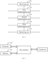
- FIG. 3 is a schematic diagram of a beam quality monitoring process provided by the present disclosure, including the following steps.
- S101 RRC configuration information and MAC-CE activation information sent by a network device side are received, and an index value of each CORESET and at least one TCI state activated in each CORESET are determined according to the RRC configuration information and the MAC-CE activation information.
- the network device side sends RRC configuration information of the PDCCH and MAC-CE activation information of the PDCCH to the user equipment, wherein the RRC configuration information includes configuration information of the PDCCH transmission mode, and the MAC-CE activation information includes one or more TCI states activated in each CORESET. Specifically, the execution steps on the network device side are described as below.
- the user equipment receives the RRC configuration information of the PDCCH and the MAC-CE activation information of the PDCCH sent by the network device side, and determines an index value of each CORESET and a TCI state(s) activated in each CORESET according to the RRC configuration information and the MAC-CE activation information.
- a transmission mode of each CORESET is determined according to the activated TCI state(s) in each CORESET, wherein the transmission mode includes a single frequency network (SFN) transmission mode and a single-point transmission mode.
- SFN single frequency network
- the user equipment determines the transmission mode of each CORESET according to the activated TCI state(s) in each CORESET.
- the user equipment determines that the transmission mode of the CORESET is the single-point transmission mode; and if the number of activated TCI states in the CORESET is two, the user equipment determines that the transmission mode of the CORESET is the SFN transmission mode.
- At least one CORESET is selected as a to-be-monitored CORESET, wherein the to-be-monitored CORESET includes a CORESET in the SFN transmission mode.
- the user equipment selects at least one CORESET from the CORESETs as the to-be-monitored CORESET.
- the number of to-be-monitored CORESETs is not limited in the present disclosure, as long as the at least one selected to-be-monitored CORESET includes a CORESET(s) in the SFN transmission mode.
- the user equipment determines that the index values of the CORESETs are CORESET 0, CORESET 1 and CORESET 2 respectively.
- the transmission mode of CORESET 0 and CORESET 1 is a single-point transmission mode, and the transmission mode of CORESET 2 is a SFN transmission mode.
- the selected to-be-monitored CORESETs may be CORESET 0 and CORESET 2, or CORESET 1 and CORESET 2, or CORESET 0, CORESET 1, and CORESET 2.
- each to-be-monitored beam failure detection reference signal (BFD RS) is determined according to a periodic CSI RS(s) associated with the activated TCI state(s) in each to-be-monitored CORESET.
- the user equipment may take the CSI RS(s) associated with the activated TCI state(s) in each to-be-monitored CORESET as the to-be-monitored BFD RS(s), or select a preset number of to-be-monitored CSI RSs as the to-be-monitored BFD RSs from the CRI RSs associated with the activated TCI states in the to-be-monitored CORESETs.
- the number of the to-be-monitored BFD RSs is not limited in the present disclosure, as long as the selected CSI RS(s) includes the CSI RS(s) associated with the activated TCI state(s) in the at least one to-be-monitored CORESET, and the at least one to-be-monitored CORESET includes at least one CORESET in the SFN transmission mode.
- S105 beam quality monitoring is performed based on each to-be-monitored BFD RS.
- the user equipment calculates a beam quality of each to-be-monitored BFD RS, and if the user equipment determines that each beam quality satisfies a preset beam failure condition, a beam failure event is triggered.
- the user equipment may calculate the beam quality of each to-be-monitored BFD RS through the following.
- the user equipment calculates the block error rate (BLER) value of each to-be-monitored BFD RS, the user equipment determines each beam quality satisfies the preset beam failure condition if the user equipment determines that each BLER value is greater than a preset BLER threshold, and a beam failure event is triggered.
- the preset BLER threshold may be 10%.
- the user equipment determines the index value of each CORESET and the TCI state (s) activated in each CORESET according to the RRC configuration information and the MAC-CE activation information, and determines the transmission mode of each CORESET according to the activated TCI state(s) in each CORESET.
- the user equipment selects at least one CORESET as the to-be-monitored CORESET, wherein the to-be-monitored CORESET includes the CORESET(s) in the SFN transmission mode.
- the user equipment determines the to-be-monitored BFD RS(s) according to the CSI RS(s) associated with the activated TCI state(s) in the to-be-monitored CORESET, and performs beam quality monitoring based on each to-be-monitored BFD RS.
- the beam quality of at least one CORESET is monitored in the present disclosure, and the at least one monitored CORESET includes the CORESET in the SFN transmission mode. Since the activated TCI states in the CORESET in the SFN transmission mode are associated with the CSI RSs of two transmission reception points, the beam qualities of the two transmission reception points can be monitored in the present disclosure.
- the beam qualities of at least one CORESET and the two transmission reception points are monitored in the present disclosure, which solves the problem in the related art that the beam quality of the PDCCH cannot be accurately reflected.
- the selecting at least one CORESET as the to-be-monitored CORESET includes: sorting the CORESETs according to a preset priority rule, and selecting at least one CORESET as the to-be-monitored CORESET according to a sorting result obtained by sorting the CORESETs according to the preset priority rule.
- the user equipment saves the preset priority rule. After the CORESETs are determined, the user equipment sorts the CORESETs according to the preset priority rule, and then selects at least one CORESET as the to-be-monitored CORESET according to the sorting result. For example, after the sorting is completed, at least one CORESET is selected as the to-be-monitored CORESET in a sequence from front to back.
- the sorting the CORESETs according to the preset priority rule includes:
- the preset priority rule in the present disclosure includes the following rules.
- the first rule is to sort the CORESETs only according to the index values of the CORESETs, wherein the CORESET with the smaller index value has the higher priority than the CORESET with the larger index value.
- the CORESETs determined by the user equipment are CORESET 0, CORESET 1 and CORESET 2.
- the CORESETs are sorted, and the sorting result is also CORESET 0, CORESET 1, and CORESET 2.
- the user equipment may take CORESET 0 and CORESET 1 as the to-be-monitored CORESETs, or take CORESET 0, CORESET 1 and CORESET 2 as the to-be-monitored CORESETs. If the transmission mode of CORESET 0 and CORESET 1 is the single-point transmission mode and the transmission mode of CORESET 2 is the SFN transmission mode, in order to ensure that the selected to-be-monitored CORESET(s) includes a CORESET in the SFN transmission mode, the user equipment may take the CORESET 0, CORESET 1 and CORESET 2 as the to-be-monitored CORESETs.
- the second rule is to sort the CORESETs only according to the transmission mode of each CORESET, wherein the CORESET in the SFN transmission mode has the higher priority than the CORESET in the single-point transmission mode.
- the ordering of CORESETs with the same transmission mode as long as the ordering of the CORESETs in the SFN transmission mode is prior to the CORESET(s) in the single-point transmission mode.
- the CORESETs determined by the user equipment are CORESET 0, CORESET 1 and CORESET 2.
- the sorting result is CORESET 2, CORESET 0, and CORESET 1, or CORESET 2, CORESET 1, and CORESET 0, and then at least one CORESET is selected, according to the sorting result, as the to-be-monitored CORESET from front to back.
- the third rule is to sort the CORESETs according to the transmission mode and an index value of each CORESET.
- the transmission mode has the higher priority than the index value
- the CORESET in the SFN transmission mode has the higher priority than the CORESET in the single-point transmission mode
- the CORESET with the smaller index value has the higher priority than the CORESET with the larger index value. That is, the CORESET in the SFN transmission mode are sorted prior to the CORESET in the single-point transmission mode, and the CORESETs of the same transmission mode are sorted according to the index values of them.
- the CORESETs determined by the user equipment are CORESET 0, CORESET 1, CORESET 2, and CORESET 3.
- the sorting result is CORESET 1, CORESET 3, CORESET 0, and CORESET 2. Then at least one CORESET is selected, according to the sorting result, as the to-be-monitored CORESET from front to back.
- the determining the transmission mode of each CORESET according to the activated TCI state(s) in each CORESET includes:
- the transmission mode of the CORESET being the SFN transmission mode is determined. If it is determined according to the MAC-CE activation information that two TCI states are activated in the CORESET, the transmission mode of the CORESET being the SFN transmission mode is determined. If it is determined according to the MAC-CE activation information that one TCI state is activated in the CORESET, the transmission mode of the CORESET being the single-point transmission mode is determined.
- the transmission mode of the CORESET being the single-point transmission mode is determined.
- the user equipment side performs the following steps.
- the determining each to-be-monitored BFD RS according to the CSI RS associated with the at least one activated TCI state in each to-be-monitored CORESET includes:
- determining each to-be-monitored BFD RS includes the following modes.
- Mode 1 after each to-be-monitored CORESET is determined, the number of to-be-monitored BFD RSs is not limited, and all the CSI RS(s) associated with the activated TCI state(s) in each to-be-monitored CORESET are taken as the to-be-monitored BFD RS(s).
- the determined to-be-monitored CORESETs are CORESET 0, CORESET 1 and CORESET 2.
- the CSI RSs associated with the TCI state(s) activated in CORESET 0 are CSI RS 0 and CSI RS 1
- the CSI RSs associated with the TCI state(s) activated in CORESET 1 are CSI RS 2 and CSI RS 3
- the CSI RS associated with the TCI state activated in CORESET 2 is CSI RS 4.
- CSI RS 0, CSI RS 1, CSI RS 2, CSI RS 3, and CSI RS 4 are all taken as the to-be-monitored BFD RSs.
- Mode 2 after each to-be-monitored CORESET is determined, all the CSI RS(s) associated with the activated TCI state(s) in each to-be-monitored CORESET is taken as to-be-monitored candidate CSI RS(s), and then a preset number of to-be-monitored candidate CSI RSs is selected as the to-be-monitored BFD RSs according to the sorting result of the CORESETs.
- the preset number of to-be-monitored candidate CSI RSs includes the CSI RS(s) associated with the activated TCI state(s) in at least one to-be-monitored CORESET, and the at least one to-be-monitored CORESET includes at least one CORESET in the SFN transmission mode.
- the determined to-be-monitored CORESETs are CORESET 0, CORESET 1 and CORESET 2.
- the CSI RSs associated with the TCI state(s) activated in CORESET 0 are CSI RS 0 and CSI RS 1
- the CSI RSs associated with the TCI state(s) activated in CORESET 1 are CSI RS 2 and CSI RS 3
- the CSI RS associated with the TCI state activated in CORESET 2 is CSI RS 4.
- the preset number is 4, and CSI RS 0, CSI RS 1, CSI RS 2, and CSI RS 3 are taken as the to-be-monitored BFD RSs.
- the user equipment side performs the following steps.
- Step 2 The user equipment may dynamically determine more BFD RSs in the BFD RS set according to the TCI states in the monitored CORESETs, the priority rule, and the maximum number X of CORESETs and/or the maximum number of BFD RSs.
- a number of CORESETs in the current bandwidth that are in the SFN transmission modes A number of CORESETs in the SFN transmission will be determined preferentially, which can be divided into the following two cases.
- Step 2-2 the UE determines Y number of BFD RSs by the determined X number of CORESETs and/or the maximum number Y of BFD RSs, which includes the following two modes.
- Mode 1 the UE may take B number of periodic CSI RSs associated with QCL in TCI states in X number of CORESETs as all BFD RSs.
- Mode 2 the UE may take B number of periodic CSI RSs associated with QCL in TCI states in X number of CORESETs as candidate CSI RSs, and then select Y number of candidate CSI RSs as BFD RSs according to the sorting result of the CORESETs, which can be divided into the following two cases.
- performing beam quality monitoring based on each to-be-monitored BFD RS includes:
- performing beam quality monitoring based on each to-be-monitored BFD RS includes the following modes.
- Mode 1 the beam quality of each to-be-monitored BFD RS is separately calculated, and for each determined beam quality, whether the beam quality satisfies a preset beam failure condition is determined. If it is determined that each beam quality satisfies the preset beam failure condition, a beam failure event is triggered.
- Mode 2 two to-be-monitored BFD RSs associated with the same CORESET are taken as a BFD RS group, then the beam quality of the BFD RS group is jointly calculated, and the beam qualities of the BFD RSs in the non-BFD RS group are calculated separately. Finally, for each determined beam quality, whether the beam quality satisfies a preset beam failure condition is determined. If it is determined that each beam quality satisfies the preset beam failure condition, a beam failure event is triggered.
- the beam quality of the BFD RS group is jointly calculated, which can more accurately reflect the beam quality of the CORESET, and which can better reflect the beam quality of the PDCCH compared with the mode of separately calculating the beam qualities of all the to-be-monitored BFD RSs.
- the separately calculating the beam quality of each to-be-monitored BFD RS includes: for each to-be-monitored BFD RS, determining a measurement output value corresponding to a measurement scale of the to-be-monitored BFD RS, determining a block error rate (BLER) value according to the measurement output value, and taking the BLER value as the beam quality of the to-be-monitored BFD RS.
- BLER block error rate
- Each to-be-monitored BFD RS is received and measured for channel estimation, and the measurement output is performed according to the measurement scale to obtain the measurement output value corresponding to the measurement scale, wherein the measurement scale may be any one of a signal to interference plus noise ratio (SINR), a signal noise ratio (SNR), or a reference signal receiving power (RSRP).
- SINR signal to interference plus noise ratio
- SNR signal noise ratio
- RSRP reference signal receiving power
- the jointly calculating the beam quality of the two to-be-monitored BFD RSs in the BFD RS group includes: determining measurement output values corresponding to measurement scales of the two to-be-monitored BFD RSs in the BFD RS group, respectively, superimposing the two measurement output values, determining a BLER value according to a measurement output value obtained by superimposing the two measurement output values, and taking the BLER value as the beam quality of the BFD RS group.
- the two to-be-monitored BFD RSs in the BFD RS group are respectively measured for channel estimation, and the measurement output is performed according to the measurement scale to obtain the measurement output values corresponding to the two to-be-monitored BFD RSs respectively.
- a new measurement output value is obtained by superimposing the measurement output values corresponding to the two to-be-monitored BFD RSs in the group, a BLER value is determined according to the new measurement output value, and the BLER value is taken as the beam quality of the BFD RS group.
- the superimposing of the measurement output values corresponding to the two to-be-monitored BFD RSs in the group may be performed by directly adding the measurement output values corresponding respectively to the two to-be-monitored BFD RSs; or the superimposing may be performed by assigning weight values to the two to-be-monitored BFD RSs respectively, and performing a weighted calculation according to the measurement output values and the weight values corresponding to the two to-be-monitored BFD RSs, to obtain the new measurement output value.
- the user equipment side performs the following steps.
- Step 3 after the user equipment determines the BFD RSs in the BFD RS group, the user equipment can measure the beam qualities of all the BFD RSs and perform threshold comparisons in the following different modes to determine whether the beam failure occurs at the current moment, and indicate a beam failure event to the high layer of the user equipment once.
- Step 4 when the number of beam failures reaches a certain number within a certain time duration (obtained by the RRC configuration), the user equipment will be triggered to send a beam failure recovery request to the network device side.
- the present disclosure proposes a beam quality monitoring method.
- the user equipment may monitor the transmission beam quality of each transmission reception point and the beam qualities of more CORESETs, which solves the problem of poor communication performance in the beam quality monitoring method in the related art.
- the UE may dynamically determine more BFD RSs in the BFD RS set according to the TCI states in the monitored CORESETs, the priority rule, and the maximum number of CORESETs and/or the maximum number of BFD RSs.
- the UE may determine the CORESETs associated with the BFD RSs through different priority rules and/or the maximum number of CORESETs. Then, the UE may dynamically determine the BFD RSs through the determined CORESETs and/or the maximum number of BFD RSs.
- the user equipment After the user equipment has determined more BFD RSs in the BFD RS group, it can measure the beam qualities of all the BFD RSs and compare them with a threshold(s) through the following different cases, to determine whether the beam failure occurs at the current moment, indicate a beam failure event to the high layer of the user equipment once, and when the number of beam failures reaches a certain number within a certain period of time, trigger the user equipment to send a beam failure recovery request to the network device side.
- Case 1 if two BFD RSs in the BFD RSs determined by the current user equipment are associated with two TCI states in the same CORESET, the user equipment may jointly calculate the beam quality of the two BFD RSs and compare it with a defined threshold, and separately calculate the beam qualities of other BFD RSs. If all the calculated beam qualities are greater than the threshold, a beam failure event is indicated to the high layer of the user equipment once.
- Case 2 if there are no two BFD RSs in the BFD RSs determined by the current user equipment associated with the two TCI states in the same CORESET, the user equipment may separately calculate the beam quality of each BFD RS and compare it with a defined threshold. If all the calculated beam qualities are greater than the threshold, a beam failure event is indicated to the high layer of the user equipment once.
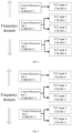
- Embodiment 1 as shown in FIG. 4 , it is assumed that the network device side configures 3 CORESETs in each unit frequency band for the user equipment, wherein each of 2 CORESETs is activated by the MAC-CE with two TCI states, and each TCI state is associated with one piece of QCL-typeA information and one piece of QCL-typeD information, and the target QCL reference signal of QCL-typeD is a periodic CSI RS.
- the specific process is as follows.
- Embodiment 2 as shown in FIG. 5 , it is assumed that the network device side configures 3 CORESETs in each unit frequency band for the user equipment, wherein each of 2 CORESETs is activated by the MAC-CE with two TCI states, and each TCI state is associated with one piece of QCL-typeA information and one piece of QCL-typeD information, and the target QCL reference signal of QCL-typeD is a periodic CSI RS.
- the specific process is as follows.
- Embodiment 3 as shown in FIG. 6 , it is assumed that the network device side configures 3 CORESETs in each unit frequency band for the user equipment, wherein each of 2 CORESETs is activated by the MAC-CE with two TCI states, and each TCI state is associated with one piece of QCL-typeA information and one piece of QCL-typeD information, and the target QCL reference signal of QCL-typeD is a periodic CSI RS.
- the specific process is as follows.
- Embodiment 4 as shown in FIG. 7 , it is assumed that the network device side configures 3 CORESETs in each unit frequency band for the user equipment, wherein each of 2 CORESETs is activated by the MAC-CE with two TCI states, and each TCI state is associated with one piece of QCL-typeA information and one piece of QCL-typeD information, and the target QCL reference signal of QCL-typeD is a periodic CSI RS.
- the specific process is as follows.
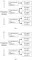
- Embodiment 5 as shown in FIG. 8 , it is assumed that the network device side configures 3 CORESETs in each unit frequency band for the user equipment, wherein the CORESETs each are activated by the MAC-CE with one TCI state, and each TCI state is associated with one piece of QCL-typeA information and one piece of QCL-typeD information, and the target QCL reference signal of QCL-typeD is a periodic CSI RS.
- the specific process is as follows.
- Embodiment 6 as shown in FIG. 9 , it is assumed that the network device side configures 3 CORESETs in each unit frequency band for the user equipment, wherein the CORESETs each are activated by the MAC-CE with one TCI state, and each TCI state is associated with one piece of QCL-typeA information and one piece of QCL-typeD information, and the target QCL reference signal of QCL-typeD is a periodic CSI RS.
- the specific process is as follows.
- Embodiment 7 as shown in FIG. 10 , it is assumed that the network device side configures 3 CORESETs in each unit frequency band for the user equipment, wherein the CORESETs each are activated by the MAC-CE with one TCI state, and each TCI state is associated with one piece of QCL-typeA information and one piece of QCL-typeD information, and the target QCL reference signal of QCL-typeD is a periodic CSI RS.
- the specific process is as follows.
- Embodiment 8 as shown in FIG. 11 , it is assumed that the network device side configures 3 CORESETs in each unit frequency band for the user equipment, wherein the CORESETs each are activated by the MAC-CE with one TCI state, and each TCI state is associated with one piece of QCL-typeA information and one piece of QCL-typeD information, and the target QCL reference signal of QCL-typeD is a periodic CSI RS.
- the specific process is as follows.
- the present disclosure proposes a beam quality monitoring method.
- the UE can dynamically determine more BFD RSs according to the TCI states in the monitored CORESETs, the priority rule, and the maximum number of CORESETs and/or the maximum number of BFD RSs, so the transmission beam quality of each transmission reception point and the beam qualities of more CORESETs are monitored, which solves the problem of poor communication performance in the beam failure monitoring method in the related art.
- FIG. 12 is a schematic structural diagram of a beam quality monitoring apparatus provided by the present disclosure, including:
- the second determination unit 123 is specifically configured to sort the CORESETs according to a preset priority rule, and select at least one CORESET as the to-be-monitored CORESET according to a sorting result obtained by sorting the CORESETs according to the preset priority rule.
- the second determination unit 123 is specifically configured to sort the CORESETs according to index values of the CORESETs, wherein a CORESET with a smaller index value has a higher priority than a CORESET with a larger index value; or sort the CORESETs according to the transmission mode of each of the CORESETs, wherein a CORESET in the SFN transmission mode has a higher priority than a CORESET in the single-point transmission mode; or sort the CORESETs according to the transmission mode and an index value of each of the CORESETs, wherein the transmission mode has a higher priority than the index value, a CORESET in the SFN transmission mode has a higher priority than a CORESET in the single-point transmission mode, and a CORESET with a smaller index value has a higher priority than a CORESET with a larger index value.
- the first determination unit 122 is specifically configured to, for each of the CORESETs, determine whether SFN configuration information of the CORESET exists in the RRC configuration information; if the SFN configuration information of the CORESET exists in the RRC configuration information and it is determined according to the MAC-CE activation information that two TCI states are activated in the CORESET, determine that the transmission mode of the CORESET is the SFN transmission mode; if the SFN configuration information of the CORESET exists in the RRC configuration information and it is determined according to the MAC-CE activation information that one TCI state is activated in the CORESET, determine that the transmission mode of the CORESET is the single-point transmission mode; and if no SFN configuration information of the CORESET exists in the RRC configuration information and it is determined according to the MAC-CE activation information that one TCI state is activated in the CORESET, determine that the transmission mode of the CORESET is the single-point transmission mode.
- the third determination unit 124 is specifically configured to take all the CSI RS associated with the at least one activated TCI state in each to-be-monitored CORESET as the to-be-monitored BFD RS; or take all the CSI RS associated with the at least one activated TCI state in each to-be-monitored CORESET as a to-be-monitored candidate CSI RS, and select a preset number of to-be-monitored candidate CSI RSs according to a sorting result for the CORESETs as to-be-monitored candidate CSI RSs.
- the monitoring unit 125 is specifically configured to separately calculate a beam quality of each to-be-monitored BFD RS, and trigger a beam failure event if it is determined that the beam quality of each to-be-monitored BFD RS satisfies a preset beam failure condition; or take two to-be-monitored BFD RSs associated with one same CORESET as a BFD RS group, jointly calculate a beam quality of the two to-be-monitored BFD RSs in the BFD RS group, separately calculate beam qualities of BFD RSs of a non-BFD RS group, and trigger a beam failure event if it is determined that each beam quality satisfies a preset beam failure condition.
- the monitoring unit 125 is specifically configured to, for each to-be-monitored BFD RS, determine a measurement output value corresponding to a measurement scale of the to-be-monitored BFD RS, determine a block error rate (BLER) value according to the measurement output value, and take the BLER value as the Beam quality of the to-be-monitored BFD RS.
- BLER block error rate
- the monitoring unit 125 is specifically configured to determine measurement output values corresponding to measurement scales of the two to-be-monitored BFD RSs in the BFD RS group, respectively, superimpose the two measurement output values, determine a BLER value according to a measurement output value obtained by superimposing the two measurement output values, and take the BLER value as the beam quality of the BFD RS group.
- an embodiment of the present disclosure provides a user equipment, including:
- the bus architecture may include any number of interconnected buses and bridges. Specifically, one or more processors represented by the processor 132 and various circuits of a memory represented by the memory 131 are linked together.
- the bus architecture can also link together various other circuits such as peripherals, voltage regulators, and power management circuits, etc., which are well known in the art and therefore will not be further described herein.
- the bus interface provides the interface.
- a transceiver may be a plurality of elements, including a transmitter and a receiver, providing units for communicating with various other devices over transmission media.
- the user interface may also be an interface capable of connecting externally and internally to required devices, and the connected devices include but not limited to keypads, monitors, speakers, microphones, joysticks, and the like.
- the processor 132 is responsible for managing the bus architecture and general processing, and the memory 131 can store data used by the processor 132 when performing operations.
- an embodiment of the present disclosure provides a computer-readable storage medium.
- the processor can execute any of the methods performed by the user equipment in each of the above-mentioned embodiments.
- the user equipment determines the index value of each CORESET and the TCI state(s) activated in each CORESET according to the RRC configuration information and the MAC-CE activation information, and determines the transmission mode of each CORESET according to the activated TCI state(s) in each CORESET.
- the user equipment selects at least one CORESET as the to-be-monitored CORESET, wherein the to-be-monitored CORESET includes the CORESET(s) in the SFN transmission mode.
- the user equipment determines the to-be-monitored BFD RS(s) according to the CSI RSs associated with the activated TCI state(s) in the to-be-monitored CORESET, and performs beam quality monitoring based on each to-be-monitored BFD RS.
- the beam quality of at least one CORESET is monitored in the present disclosure, and the at least one monitored CORESET includes the CORESET in the SFN transmission mode. Since the activated TCI states in the CORESET in the SFN transmission mode are associated with the CSI RSs of two transmission reception points, the beam qualities of the two transmission reception points can be monitored in the present disclosure.
- the beam qualities of at least one CORESET and the two transmission reception points are monitored in the present disclosure, which solves the problem in the related art that the beam quality of the PDCCH cannot be accurately reflected.
- the embodiments of the present disclosure may be provided as methods, systems, or computer program products. Accordingly, the present disclosure can take the form of an entirely hardware embodiment, an entirely software embodiment, or an embodiment combining software and hardware aspects. Furthermore, the present disclosure may take the form of a computer program product embodied on one or more computer-usable storage medium (including but not limited to the disk storage, compact disc read-only memory (CD-ROM), optical storage, etc.) having computer-usable program codes embodied therein.
- CD-ROM compact disc read-only memory
- optical storage etc.
- These computer program instructions may also be stored in a computer-readable memory capable of directing a computer or other programmable data processing apparatus to operate in a specific manner, such that the instructions stored in the computer-readable memory produce an article of manufacture including an instruction apparatus, and the instructions apparatus realizes the function specified in one or more procedures of the flowchart and/or one or more blocks of the block diagram.
Landscapes
- Engineering & Computer Science (AREA)
- Signal Processing (AREA)
- Computer Networks & Wireless Communication (AREA)
- Quality & Reliability (AREA)
- Physics & Mathematics (AREA)
- Electromagnetism (AREA)
- Power Engineering (AREA)
- Monitoring And Testing Of Transmission In General (AREA)
- Mobile Radio Communication Systems (AREA)
- Data Exchanges In Wide-Area Networks (AREA)
Applications Claiming Priority (2)
| Application Number | Priority Date | Filing Date | Title |
|---|---|---|---|
| CN202110901975.1A CN115706685B (zh) | 2021-08-06 | 2021-08-06 | 一种波束质量监测方法、装置、设备及介质 |
| PCT/CN2022/106471 WO2023011163A1 (zh) | 2021-08-06 | 2022-07-19 | 一种波束质量监测方法、装置、设备及介质 |
Publications (2)
| Publication Number | Publication Date |
|---|---|
| EP4383791A1 true EP4383791A1 (de) | 2024-06-12 |
| EP4383791A4 EP4383791A4 (de) | 2024-12-18 |
Family
ID=85155150
Family Applications (1)
| Application Number | Title | Priority Date | Filing Date |
|---|---|---|---|
| EP22851877.5A Pending EP4383791A4 (de) | 2021-08-06 | 2022-07-19 | Verfahren und vorrichtung zur überwachung der strahlqualität sowie vorrichtung und medium |
Country Status (6)
| Country | Link |
|---|---|
| US (1) | US20250150177A1 (de) |
| EP (1) | EP4383791A4 (de) |
| JP (1) | JP7748537B2 (de) |
| KR (1) | KR20240038794A (de) |
| CN (2) | CN115706685B (de) |
| WO (1) | WO2023011163A1 (de) |
Families Citing this family (1)
| Publication number | Priority date | Publication date | Assignee | Title |
|---|---|---|---|---|
| CN121771739A (zh) * | 2024-09-29 | 2026-03-31 | 大唐移动通信设备有限公司 | 事件评估方法、装置及可读存储介质 |
Family Cites Families (5)
| Publication number | Priority date | Publication date | Assignee | Title |
|---|---|---|---|---|
| WO2019095299A1 (en) * | 2017-11-17 | 2019-05-23 | Qualcomm Incorporated | Determining beam failure based on a dynamic range of transmission power ratios |
| US11095355B2 (en) * | 2018-05-10 | 2021-08-17 | Comcast Cable Communications, Llc | Prioritization in beam failure recovery procedures |
| EP3567967B1 (de) * | 2018-05-10 | 2021-02-24 | ASUSTek Computer Inc. | Verfahren und vorrichtung zur strahlanzeige für uplink-übertragung in einem drahtloskommunikationssystem |
| CN111601371B (zh) * | 2019-06-27 | 2022-03-01 | 维沃移动通信有限公司 | 链路管理方法、唤醒信号检测方法、终端设备和网络设备 |
| CN111817835B (zh) * | 2020-06-02 | 2023-04-07 | 中国信息通信研究院 | 一种波束切换指示方法、设备和系统 |
-
2021
- 2021-08-06 CN CN202110901975.1A patent/CN115706685B/zh active Active
- 2021-08-06 CN CN202510040913.4A patent/CN119892564A/zh active Pending
-
2022
- 2022-07-19 WO PCT/CN2022/106471 patent/WO2023011163A1/zh not_active Ceased
- 2022-07-19 US US18/681,302 patent/US20250150177A1/en active Pending
- 2022-07-19 JP JP2024507030A patent/JP7748537B2/ja active Active
- 2022-07-19 EP EP22851877.5A patent/EP4383791A4/de active Pending
- 2022-07-19 KR KR1020247007004A patent/KR20240038794A/ko active Pending
Also Published As
| Publication number | Publication date |
|---|---|
| EP4383791A4 (de) | 2024-12-18 |
| US20250150177A1 (en) | 2025-05-08 |
| KR20240038794A (ko) | 2024-03-25 |
| WO2023011163A1 (zh) | 2023-02-09 |
| JP7748537B2 (ja) | 2025-10-02 |
| JP2024529656A (ja) | 2024-08-08 |
| CN119892564A (zh) | 2025-04-25 |
| CN115706685A (zh) | 2023-02-17 |
| CN115706685B (zh) | 2025-02-14 |
Similar Documents
| Publication | Publication Date | Title |
|---|---|---|
| US12483916B2 (en) | Resource measurement method and apparatus | |
| EP3852288B1 (de) | Leistungsanzeigeverfahren und -vorrichtungen | |
| US20220295323A1 (en) | Measurement configuration and reporting method, apparatus and user device | |
| US11930550B2 (en) | Equipment for beam failure reporting and beam failure reporting method | |
| US9467262B2 (en) | Method for configuring reference signal, UE, and eNB | |
| US11950112B2 (en) | User equipment for beam failure detection and beam failure detection method | |
| US20210258062A1 (en) | Secondary cell beam recovery | |
| CN114363916B (zh) | 一种用于波束失败检测的方法、装置及系统 | |
| CN109391995B (zh) | 一种干扰测量方法、终端设备及网络设备 | |
| CN115150025B (zh) | Csi反馈方法、相关设备及可读存储介质 | |
| US20230239870A1 (en) | Method and apparatus for determining and configuring uplink channel parameter | |
| JP2021521750A5 (de) | ||
| CN115150036B (zh) | 信道状态信息csi报告的映射方法、终端及网络侧设备 | |
| EP2871880A1 (de) | Virtuelles trägeraggregationsverfahren, basisstation und benutzervorrichtung | |
| KR20210127217A (ko) | 빔 보고 방법 및 장치 | |
| CN113950093B (zh) | 一种csi测量上报方法、终端及网络侧设备 | |
| EP4383791A1 (de) | Verfahren und vorrichtung zur überwachung der strahlqualität sowie vorrichtung und medium | |
| US11206566B2 (en) | Method for downlink signal transmission, terminal device and network device | |
| WO2022083532A1 (zh) | Csi计算方法、用户终端及计算机可读存储介质 | |
| GB2633634A (en) | Event-triggered CSI reporting | |
| US20230388841A1 (en) | Channel state information reporting | |
| KR20250035583A (ko) | 채널 상태 정보 처리 방법, 통신 노드 및 저장 매체 | |
| US20240030986A1 (en) | Csi feedback for multi-pdsch transmission | |
| CN119921883A (zh) | 一种信道预测方法及相关设备 | |
| CN120345323A (zh) | 用于多个发送和接收点的波束故障恢复方法 |
Legal Events
| Date | Code | Title | Description |
|---|---|---|---|
| STAA | Information on the status of an ep patent application or granted ep patent |
Free format text: STATUS: THE INTERNATIONAL PUBLICATION HAS BEEN MADE |
|
| PUAI | Public reference made under article 153(3) epc to a published international application that has entered the european phase |
Free format text: ORIGINAL CODE: 0009012 |
|
| STAA | Information on the status of an ep patent application or granted ep patent |
Free format text: STATUS: REQUEST FOR EXAMINATION WAS MADE |
|
| 17P | Request for examination filed |
Effective date: 20240226 |
|
| AK | Designated contracting states |
Kind code of ref document: A1 Designated state(s): AL AT BE BG CH CY CZ DE DK EE ES FI FR GB GR HR HU IE IS IT LI LT LU LV MC MK MT NL NO PL PT RO RS SE SI SK SM TR |
|
| DAV | Request for validation of the european patent (deleted) | ||
| DAX | Request for extension of the european patent (deleted) | ||
| A4 | Supplementary search report drawn up and despatched |
Effective date: 20241119 |
|
| RIC1 | Information provided on ipc code assigned before grant |
Ipc: H04W 24/02 20090101AFI20241113BHEP |