EP4383563A1 - Method and system for processing an analog signal - Google Patents
Method and system for processing an analog signal Download PDFInfo
- Publication number
- EP4383563A1 EP4383563A1 EP22212155.0A EP22212155A EP4383563A1 EP 4383563 A1 EP4383563 A1 EP 4383563A1 EP 22212155 A EP22212155 A EP 22212155A EP 4383563 A1 EP4383563 A1 EP 4383563A1
- Authority
- EP
- European Patent Office
- Prior art keywords
- signal
- chop
- frequency
- chopping
- analog
- Prior art date
- Legal status (The legal status is an assumption and is not a legal conclusion. Google has not performed a legal analysis and makes no representation as to the accuracy of the status listed.)
- Pending
Links
- 238000000034 method Methods 0.000 title claims abstract description 31
- 238000005070 sampling Methods 0.000 claims abstract description 65
- 230000002596 correlated effect Effects 0.000 claims abstract description 27
- 238000001914 filtration Methods 0.000 claims abstract description 22
- 238000001228 spectrum Methods 0.000 description 5
- 230000002238 attenuated effect Effects 0.000 description 3
- 239000000872 buffer Substances 0.000 description 2
- 230000000875 corresponding effect Effects 0.000 description 2
- 230000000694 effects Effects 0.000 description 2
- 230000008569 process Effects 0.000 description 2
- 230000006641 stabilisation Effects 0.000 description 2
- 238000011105 stabilization Methods 0.000 description 2
- 230000000087 stabilizing effect Effects 0.000 description 2
- 101100042630 Caenorhabditis elegans sin-3 gene Proteins 0.000 description 1
- 229920000954 Polyglycolide Polymers 0.000 description 1
- XUIMIQQOPSSXEZ-UHFFFAOYSA-N Silicon Chemical compound [Si] XUIMIQQOPSSXEZ-UHFFFAOYSA-N 0.000 description 1
- 230000004075 alteration Effects 0.000 description 1
- 238000006243 chemical reaction Methods 0.000 description 1
- 230000008878 coupling Effects 0.000 description 1
- 238000010168 coupling process Methods 0.000 description 1
- 238000005859 coupling reaction Methods 0.000 description 1
- 230000001419 dependent effect Effects 0.000 description 1
- 238000011161 development Methods 0.000 description 1
- 230000018109 developmental process Effects 0.000 description 1
- 238000012986 modification Methods 0.000 description 1
- 230000004048 modification Effects 0.000 description 1
- 235000010409 propane-1,2-diol alginate Nutrition 0.000 description 1
- 229910052710 silicon Inorganic materials 0.000 description 1
- 239000010703 silicon Substances 0.000 description 1
Images



Classifications
-
- H—ELECTRICITY
- H03—ELECTRONIC CIRCUITRY
- H03F—AMPLIFIERS
- H03F3/00—Amplifiers with only discharge tubes or only semiconductor devices as amplifying elements
- H03F3/38—DC amplifiers with modulator at input and demodulator at output; Modulators or demodulators specially adapted for use in such amplifiers
-
- H—ELECTRICITY
- H04—ELECTRIC COMMUNICATION TECHNIQUE
- H04B—TRANSMISSION
- H04B1/00—Details of transmission systems, not covered by a single one of groups H04B3/00 - H04B13/00; Details of transmission systems not characterised by the medium used for transmission
- H04B1/06—Receivers
- H04B1/10—Means associated with receiver for limiting or suppressing noise or interference
- H04B1/1027—Means associated with receiver for limiting or suppressing noise or interference assessing signal quality or detecting noise/interference for the received signal
-
- H—ELECTRICITY
- H03—ELECTRONIC CIRCUITRY
- H03F—AMPLIFIERS
- H03F1/00—Details of amplifiers with only discharge tubes, only semiconductor devices or only unspecified devices as amplifying elements
- H03F1/26—Modifications of amplifiers to reduce influence of noise generated by amplifying elements
-
- H—ELECTRICITY
- H03—ELECTRONIC CIRCUITRY
- H03F—AMPLIFIERS
- H03F3/00—Amplifiers with only discharge tubes or only semiconductor devices as amplifying elements
- H03F3/181—Low-frequency amplifiers, e.g. audio preamplifiers
-
- H—ELECTRICITY
- H04—ELECTRIC COMMUNICATION TECHNIQUE
- H04B—TRANSMISSION
- H04B1/00—Details of transmission systems, not covered by a single one of groups H04B3/00 - H04B13/00; Details of transmission systems not characterised by the medium used for transmission
- H04B1/06—Receivers
- H04B1/16—Circuits
Definitions
- the invention relates to analog signal processing, especially to stabilize instrumentation amplifiers in the signal processing path by means of a chopper and a correlated double sampling scheme.
- chopper-based stabilization of instrumentation amplifiers may be performed to reduce the input direct current (DC) offset and low-frequency input noise that may degrade the performance of precision amplifiers.
- the input signal may be first multiplied by a chopping signal, then may be amplified and may be multiplied again by a similar switching function, and finally may be low-pass filtered.
- the first multiplication may translate the input signal spectrum into the high-frequency (HF) region and the second multiplication may recover the amplified original signal by demodulating the signal back to the baseband.
- the input-referred amplifier DC offset and low-frequency noise components may only go through the second multiplication process, and thus the DC offset may be converted into an HF component at the output and may be fully attenuated by the low-pass filter (LPF).
- LPF low-pass filter
- the LPF may require a low cut-off frequency and therefore may require an appreciable silicon area.
- the above-mentioned chopper stabilization can be implemented in the channel for both the IA and the ADC.
- a bulky LPF may be needed, especially before the signal can be sampled by the ADC.
- a buffer or a programmable gain amplifier (PGA) may be needed in front of the ADC, which may add additional power consumption to the channel.
- an object of the invention is to provide a method and a system for processing an analog signal, while stabilizing an instrumentation amplifier in a sensing channel to facilitate a more relaxed low-pass filtration (i.e., size constrain) and to reduce the overall power consumption, and further to improve the gain accuracy of the filtered signal.
- a method for processing an analog signal comprises the steps of modulating the analog signal using a chopping signal with a chopping frequency f chop to generate a modulated signal, amplifying the modulated signal to generate an amplified signal, low-pass filtering the amplified signal to generate a filtered signal comprising at least one harmonic of the modulated signal, and sub-sampling the filtered signal and performing correlated double sampling operation by subtracting the samples at the chopping frequency.
- the correlated double sampling operation may correspond to a discrete time signal processing technique that may receive or select two samples, especially two opposite or phase-shifted samples, after the sub-sampling operation and may subtract the samples.
- the subtraction may eliminate the input-referred amplifier DC offset and/or low-frequency noise components, while the useful signal component may be doubled in amplitude.
- the modulation may up-convert the signal at the chopping frequency, whereby input-referred amplifier DC offset and low-frequency noise components may remain at the baseband or DC.
- the de-modulation may be performed by sub-sampling and further by a correlated double sampling by subtracting the samples, especially to facilitate filtering at or around the chopping frequency to extract the signal and to eliminate the noise components, e.g., high-pass filtering at or around the chopping frequency to filter out the noise components at the baseband or DC.
- the low-pass filtering of the amplified signal to include one or more harmonics may improve the gain accuracy, especially by sub-sampling the chopping harmonics.
- the strict requirements, e.g., the low cut-off, for the low-pass filtration may be relaxed to facilitate compact filters as well as to eliminate the necessity of having buffers and/or PGAs before the analog-to-digital signal conversion.
- the method further comprises the step of generating a square wave of frequency f chop as the chopping signal, especially a unit symmetrical square wave of frequency f chop as the chopping signal.
- the method further comprises the step of low-pass filtering the amplified signal with a cutoff frequency of at least 3 ⁇ f chop , preferably a cutoff frequency of 3.5 ⁇ f chop .
- the method further comprises the step of sub-sampling the filtered signal with a sampling frequency of N ⁇ 2 ⁇ f chop , where N is an integer.
- At least one higher order chopping harmonic may be filtered along with the up-modulated signal at the chopping frequency, which may improve the gain accuracy of the signal and further may decrease the noise components due to sub-sampling of the signals and the noise components.
- a low-pass filtering with a cutoff frequency of 3 ⁇ f chop may reduce the noise but give a higher gain error
- a low-pass filtering with a cutoff frequency of 4 ⁇ f chop may give a lower gain error but more noise.
- the method further comprises the step of applying sinc filtering and/or zero-order-hold to the samples before and/or after the correlated double sampling operation.
- the samples may be attenuated by a sinc filter and/or by a zero-order hold model based on the sampling frequency to reconstruct the original signal.
- the method further comprises the step of adding a gain factor in digital domain after performing the correlated double sampling operation.
- the gain accuracy can be further improved.
- a system for processing an analog signal comprises a chopper configured to modulate the analog signal using a chopping signal with a chopping frequency f chop to generate a modulated signal, an amplifier configured to amplify the modulated signal to generate an amplified signal, a low-pass filter configured to filter the amplified signal to generate a filtered signal comprising at least one harmonic of the modulated signal, an analog-to-digital converter configured to sub-sample the filtered signal, and a correlated double sampling block configured to perform correlated double sampling operation by subtracting the samples at the chopping frequency.
- the system further comprises a signal generator configured to generate a square wave of frequency f chop as the chopping signal.
- the low-pass filter is configured to filter the amplified signal with a cutoff frequency of at least 3 ⁇ f chop , preferably a cutoff frequency of 3.5 ⁇ f chop .
- the low-pass filter is further configured to settle before the sub-sampling of the filtered signal.
- the low-pass filter may reduce or eliminate aliasing effects in the filtered signal.
- the analog-to-digital converter is configured to sub-sample the filtered signal with a sampling frequency of N ⁇ 2 ⁇ f chop , where N is an integer.
- the analog-to-digital converter is a successive approximation register analog-to-digital converter.
- the overall power consumption can be further reduced.
- the correlated double sampling block is further configured to apply sinc filtering and/or zero-order-hold to the samples before and/or after the correlated double sampling operation.
- the correlated double sampling block may attenuate the samples by a sinc filter and/or by a zero-order hold model based on the sampling frequency of the analog-to-digital converter to reconstruct the original signal.
- the correlated double sampling block is further configured to add a gain factor in digital domain after performing the correlated double sampling operation.
- the amplifier is an instrumentation amplifier, and the analog signal is a sensor generated signal, especially a micro-level signal.
- the amplifier may be configured to measure physiological signals, such as but not limited to electrocardiogram (ECG) signals, electromyogram (EMG) signals, electroencephalogram (EEG) signals, pressure signals, impedance signals, and motion signals.
- system according to the second aspect corresponds to the method according to the first aspect and its implementation forms. Accordingly, the system according to the second aspect achieves the same advantages and effects as the method of the first aspect and its respective implementation forms.
- Fig. 1 an exemplary embodiment of the method 100 according to the first aspect of the invention is illustrated.
- a first step 101 an analog signal is modulated using a chopping signal with a chopping frequency to generate a modulated signal.
- the modulated signal is amplified to generate an amplified signal.
- the amplified signal is low-pass filtered to generate a filtered signal comprising at least one harmonic of the modulated signal.
- the filtered signal is sub-sampled and correlated double sampling operation is performed by subtracting the samples at the chopping frequency.
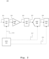
- the system 200 may comprise means (not shown) for receiving an analog signal 201, especially a sensor generated signal, and may provide a sensing channel or a readout channel in order to process the analog signal 201.
- the means for receiving the analog signal 201 may comprise or be a sensor readout unit or circuitry or interface, for example, a Wheatstone bridge-based readout circuitry or any conventional sensor readout unit or circuitry or interface known in the art.
- the means for receiving the analog signal 201 may receive the analog signal 201 through a wired connection or wirelessly.
- the system 200 may further comprise a chopper 202 that may receive the analog signal 201 and may modulate the analog signal 201 using a chopping signal 212 with a chopping frequency f chop to generate a modulated signal 203.
- a chopper should be understood as a multiplier or a modulator that may multiply or mix an input signal with a carrier signal in order to up-modulate or to shift the input signal from the baseband to the frequency of the carrier signal in the frequency spectrum including the generation of corresponding signal harmonics, e.g., due to the modulation with a square wave chopping signal.
- the system 200 may further comprise an amplifier 204 operably coupled to the chopper 202.
- the amplifier 204 may receive the modulated signal 203 at one or more inputs of the amplifier 204 and may amplify the modulated signal 203 to generate an amplified signal 205.
- the amplifier 204 may be a band-limited amplifier having a bandwidth of about 35 ⁇ f chop .
- the amplifier 204 may be designed to have a bandwidth based on the gain accuracy requirements, e.g., a bandwidth lower than 35 ⁇ f chop that may increase the gain error.
- the amplified 204 may introduce input-referred amplifier DC offset and low-frequency noise components, hereinafter referred as noise signal, while amplifying the modulated signal 203.
- the noise signal introduced by the amplifier 204 may remain at the baseband or at DC in the frequency spectrum.
- the system 200 may further comprise a low-pass filter (LPF) 206 operably coupled to the amplifier 204.
- the LPF 206 may receive the amplifier signal 205 and may filter the amplified signal 205 to generate a filtered signal 207.
- the LPF 206 may have a cut-off frequency of about 3.5 ⁇ f chop .
- the filtered signal 207 may comprise one or more harmonic components or chopping harmonics present in the frequency spectrum due to the chopping operation.
- the chopping signal 212 may be a square wave of frequency f chop .
- the modulated signal 203 generated by the chopper 202 may comprise the analog signal 201 at the chopping frequency f chop , a first (odd) harmonic component at the frequency 3 ⁇ f chop , a second (odd) harmonic component at the frequency 5 ⁇ f chop and so on in the frequency spectrum.
- the LPF 206 may filter the amplified signal 205 with a cut-off frequency of about 3.5 ⁇ f chop
- the filtered signal 207 may comprise the noise signal at the baseband, the analog signal 201 at the chopping frequency f chop , and the harmonic component at the frequency 3 ⁇ f chop .
- the system may further comprise an analog-to-digital converter (ADC) 208 operably coupled to the LPF 206.
- ADC analog-to-digital converter
- the ADC 208 may receive the filtered signal 207 and may perform sub-sampling of the filtered signal 207 to generate discrete samples 209.
- the ADC 208 may sub-sample the filtered signal 207 with a sampling frequency of N ⁇ 2 ⁇ f chop , e.g., with a sampling frequency of 2 ⁇ f chop for sampling twice during one chopping period T chop .
- the system may further comprise a correlated double sampling (CDS) block 210 operably coupled to the ADC 208.
- the CDS block 210 may operate at the chopping frequency f chop , may receive the samples 209 from the ADC 208, and may perform correlated double sampling operation by subtracting the samples 209 at the chopping frequency f chop .
- the ADC 208 may provide two samples corresponding to two opposite signal level instances or successive levels.
- the CDS block 210 may subtract the samples, which may eliminate the noise signal, however, the useful signal may be doubled in amplitude.
- the system may further comprise a signal generator 211 operably coupled to the chopper 202, the ADC 208, and the CDS block 210.
- the signal generator 211 may generate the chopping signal 212 and may provide the chopping signal 212 to the chopper 202.
- the signal generator 211 may further generate the sub-sampling clock 213 and may provide the sampling clock 213 to the ADC 208.
- the signal generator may further generate the CDS clock 214 and may provide the CDS clock 214 to the CDS block 210.
- the coupling between the above-mentioned entities may correspond to a single-ended connection or a differential connection.
- the CDS block 210 may comprise a first decimation block 301 that may receive the ADC samples 209 with a sampling frequency of N ⁇ 2 ⁇ f chop and may decimate or down-sample the samples 209 by N samples, thereby resulting the decimated samples 302 at a sampling frequency of 2 ⁇ f chop .
- the first decimation block 301 may perform a zero-order hold operation or sinc filtering to attenuate the ADC samples 209.
- the CDS block 210 may further comprise a subtraction block 303 operably coupled to the first decimation block 301.
- the subtraction block 303 may operate at the chopping frequency f chop , may receive the decimated samples 302 from the first decimation block 301, and may subtract the samples 302 at the chopping frequency f chop to generate subtracted samples 304.
- the CDS block 210 may further comprise a second decimation block 305 operably coupled to the subtraction block 303.
- the second decimation block 305 may receive the subtracted samples 304 and may decimate or down-sample the samples 304 by 2 samples, thereby resulting the further decimated samples 306 at a sampling frequency of f chop .
- the second decimation block 305 may perform a zero-order hold operation or sinc filtering to attenuate the subtracted samples 304.
- the CDS block 210 may further comprise a third decimation block 307 operably coupled to the second decimation block 305.
- the third decimation block 307 may receive the further decimated samples 306 and may decimate or down-sample the samples 304 to generate the output discrete signal 308 at a suitable frequency, e.g., 40 Hz.
- the third decimation block 307 may perform a zero-order hold operation or sinc filtering to attenuate the further decimated samples 306.
- the signal 201 may correspond to the analog signal 201 comprising the frequency components 400 at the baseband.
- the signal 203/205 may correspond to the chopper output 203 or the amplifier output 205.
- the noise components 401 and 402 may correspond to the combination of the input-referred amplifier DC offset and low-frequency noise from the amplifier 204.
- the original baseband frequency components of the noisy modulated signal 203/205 are modulated and are shown at the odd harmonics, e.g., the frequency component 400 at f chop , the frequency component 403 at 3 ⁇ f chop , the frequency component 405 at 5 ⁇ f chop , and so on.
- the signal 207 may correspond to the filter output, i.e., the ADC input 207, where the LPF 206 may apply a cut-off frequency of 3.5 ⁇ f chop , as shown by the filter band 406, especially to include the noise components 401, 402 at the baseband, the frequency component 400 at f chop , and the frequency component 403 at 3 ⁇ f chop .
- the chopper 202 may up-modulate the analog signal 201 A ⁇ cos( ⁇ in t ), where A is the signal amplitude and ⁇ in is the signal frequency, e.g., with a square wave of +1 and -1.
- the Fourier expansion of the chopping signal 212 can be expressed as: 4 ⁇ sin ⁇ chop t + 1 3 sin 3 ⁇ chop t + 1 5 sin 5 ⁇ chop t + ... where ⁇ chop is the chopping frequency.
- the first term of the modulated signal 203 can be expressed as: 4 ⁇ ⁇ A ⁇ 1 2 sin ⁇ chop ⁇ ⁇ in t ⁇ 1 2 sin ⁇ chop + ⁇ in t
- the signal 209 may correspond to the ADC output 209, where the ADC 208 may operate at a sampling frequency of 2 ⁇ f chop .
- the ADC 208 may sub-sample all signals greater than f s /2, which may result in the amplitude A due to the sub-sampling of the frequency component 400 at f chop and the frequency component 403 at 3 ⁇ f chop , as shown by the frequency component 407, thereby reducing the gain error.
- the ADC 208 may sub-sample the noise components, e.g., the noise components at 2 ⁇ f chop to the baseband.
- the LPF 206 may settle before the ADC 208 takes samples.
- the signal 306 may correspond to the CDS block 210 output signal 306 of Fig. 3 .
- the CDS block 210 may subtract the ADC samples at f chop to demodulate the frequency components 407 back to the baseband, as shown by the frequency component 408, especially by providing band-pass filtration at f chop .
- the noise component 401 at the baseband can be eliminated because of the high-pass filtration at or around f chop or f s /2, and the noise component 402 can be eliminated or minimized by sample subtraction.
- the effective noise components at the CDS block 210 output are shown as the noise components 409 and 410, e.g., the noise component 409 may correspond to the attenuated DC offset of the amplifier 204.
- the ADC 208 may take samples at the edges of the successive signal levels (top left figure) .
- the CDS block 210 may subtract said two successive samples, e.g., with a zero-order hold at a sampling frequency of f chop .
- the noise signal can be reduced, while at the same time due to the opposite nature of the actual signal component, the resultant signal may be doubled in amplitude.
- the signal-to-noise ratio (SNR) may remain the same.
- the ADC 208 may take samples at different instances with a defined sampling span on the successive signal levels (bottom left figure).
- the ADC 208 may take samples at the edges of the successive signal levels (bottom right figure) or may take samples at different instances with a defined sampling span on the successive signal levels (not shown).
- the system 600 may correspond to the system 200, e.g., the system 600 may comprise the chopper 202, the amplifier 204, the LPF 206, the ADC 208, the CDS block 210, and the signal generator 211.
- the system 600 may differ from the system 200 in that the system 600 may additionally comprise a gain block 601, especially coupled to the CDS block 210, in order to apply a digital gain at the CDS block 210 output.
- the system 600 may omit the LPF 206, and the digital gain provided by the gain block 601 may be defined to reduce the gain error to improve the gain accuracy.
- the system 600 may include both the LPF 206 and the gain block 601 to further reduce the gain error, thereby further improving the gain accuracy.
Landscapes
- Engineering & Computer Science (AREA)
- Computer Networks & Wireless Communication (AREA)
- Signal Processing (AREA)
- Power Engineering (AREA)
- Multimedia (AREA)
- Analogue/Digital Conversion (AREA)
- Amplifiers (AREA)
Abstract
Description
- The invention relates to analog signal processing, especially to stabilize instrumentation amplifiers in the signal processing path by means of a chopper and a correlated double sampling scheme.
- Generally, chopper-based stabilization of instrumentation amplifiers (IAs) may be performed to reduce the input direct current (DC) offset and low-frequency input noise that may degrade the performance of precision amplifiers. In this regard, the input signal may be first multiplied by a chopping signal, then may be amplified and may be multiplied again by a similar switching function, and finally may be low-pass filtered.
- As a result, the first multiplication may translate the input signal spectrum into the high-frequency (HF) region and the second multiplication may recover the amplified original signal by demodulating the signal back to the baseband. On the other hand, the input-referred amplifier DC offset and low-frequency noise components may only go through the second multiplication process, and thus the DC offset may be converted into an HF component at the output and may be fully attenuated by the low-pass filter (LPF).
- For example, the document M. Belloni et al., "A micropower chopper-CDS operational amplifier," IEEE Journal of Solid-State Circuits, vol. 45, no. 12, pp. 2521-2529, December 2010 discloses a chopper technique for stabilizing an amplifier.
- However, the LPF may require a low cut-off frequency and therefore may require an appreciable silicon area. Furthermore, for a high-precision channel containing a low-noise IA and an analog-to-digital converter (ADC), the above-mentioned chopper stabilization can be implemented in the channel for both the IA and the ADC.
- In this regard, after the de-modulation of the IA, a bulky LPF may be needed, especially before the signal can be sampled by the ADC. Moreover, due to the presence of the LPF, a buffer or a programmable gain amplifier (PGA) may be needed in front of the ADC, which may add additional power consumption to the channel.
- Accordingly, an object of the invention is to provide a method and a system for processing an analog signal, while stabilizing an instrumentation amplifier in a sensing channel to facilitate a more relaxed low-pass filtration (i.e., size constrain) and to reduce the overall power consumption, and further to improve the gain accuracy of the filtered signal.
- The object is solved by the features of the first independent claim for the method and by the features of the second independent claim for the system. The dependent claims contain further developments.
- According to a first aspect of the invention, a method for processing an analog signal is provided. The method comprises the steps of modulating the analog signal using a chopping signal with a chopping frequency fchop to generate a modulated signal, amplifying the modulated signal to generate an amplified signal, low-pass filtering the amplified signal to generate a filtered signal comprising at least one harmonic of the modulated signal, and sub-sampling the filtered signal and performing correlated double sampling operation by subtracting the samples at the chopping frequency.
- In this regard, the correlated double sampling operation may correspond to a discrete time signal processing technique that may receive or select two samples, especially two opposite or phase-shifted samples, after the sub-sampling operation and may subtract the samples. The subtraction may eliminate the input-referred amplifier DC offset and/or low-frequency noise components, while the useful signal component may be doubled in amplitude.
- Therefore, the modulation may up-convert the signal at the chopping frequency, whereby input-referred amplifier DC offset and low-frequency noise components may remain at the baseband or DC. Furthermore, instead of performing a second modulation with the chopping signal, the de-modulation may be performed by sub-sampling and further by a correlated double sampling by subtracting the samples, especially to facilitate filtering at or around the chopping frequency to extract the signal and to eliminate the noise components, e.g., high-pass filtering at or around the chopping frequency to filter out the noise components at the baseband or DC.
- Moreover, the low-pass filtering of the amplified signal to include one or more harmonics, i.e., the chopping harmonics, may improve the gain accuracy, especially by sub-sampling the chopping harmonics. Advantageously, the strict requirements, e.g., the low cut-off, for the low-pass filtration may be relaxed to facilitate compact filters as well as to eliminate the necessity of having buffers and/or PGAs before the analog-to-digital signal conversion.
- Preferably, the method further comprises the step of generating a square wave of frequency fchop as the chopping signal, especially a unit symmetrical square wave of frequency fchop as the chopping signal.
- Preferably, the method further comprises the step of low-pass filtering the amplified signal with a cutoff frequency of at least 3×fchop, preferably a cutoff frequency of 3.5×fchop. In addition, the method further comprises the step of sub-sampling the filtered signal with a sampling frequency of N×2×fchop, where N is an integer.
- Advantageously, at least one higher order chopping harmonic, e.g., one higher order odd harmonic because of the square wave chopping signal, may be filtered along with the up-modulated signal at the chopping frequency, which may improve the gain accuracy of the signal and further may decrease the noise components due to sub-sampling of the signals and the noise components. For example, a low-pass filtering with a cutoff frequency of 3×fchop may reduce the noise but give a higher gain error, whereas a low-pass filtering with a cutoff frequency of 4×fchop may give a lower gain error but more noise.
- Preferably, the method further comprises the step of applying sinc filtering and/or zero-order-hold to the samples before and/or after the correlated double sampling operation. For instance, the samples may be attenuated by a sinc filter and/or by a zero-order hold model based on the sampling frequency to reconstruct the original signal.
- Preferably, the method further comprises the step of adding a gain factor in digital domain after performing the correlated double sampling operation. Advantageously, for example, the gain accuracy can be further improved.
- According to a second aspect of the invention, a system for processing an analog signal is provided. The system comprises a chopper configured to modulate the analog signal using a chopping signal with a chopping frequency fchop to generate a modulated signal, an amplifier configured to amplify the modulated signal to generate an amplified signal, a low-pass filter configured to filter the amplified signal to generate a filtered signal comprising at least one harmonic of the modulated signal, an analog-to-digital converter configured to sub-sample the filtered signal, and a correlated double sampling block configured to perform correlated double sampling operation by subtracting the samples at the chopping frequency.
- Preferably, the system further comprises a signal generator configured to generate a square wave of frequency fchop as the chopping signal.
- Preferably, the low-pass filter is configured to filter the amplified signal with a cutoff frequency of at least 3×fchop, preferably a cutoff frequency of 3.5×fchop.
- Preferably, the low-pass filter is further configured to settle before the sub-sampling of the filtered signal. Advantageously, the low-pass filter may reduce or eliminate aliasing effects in the filtered signal.
- Preferably, the analog-to-digital converter is configured to sub-sample the filtered signal with a sampling frequency of N×2×fchop, where N is an integer.
- Preferably, the analog-to-digital converter is a successive approximation register analog-to-digital converter. Advantageously, for example, the overall power consumption can be further reduced.
- Preferably, the correlated double sampling block is further configured to apply sinc filtering and/or zero-order-hold to the samples before and/or after the correlated double sampling operation. For example, the correlated double sampling block may attenuate the samples by a sinc filter and/or by a zero-order hold model based on the sampling frequency of the analog-to-digital converter to reconstruct the original signal.
- Preferably, the correlated double sampling block is further configured to add a gain factor in digital domain after performing the correlated double sampling operation.
- Preferably, the amplifier is an instrumentation amplifier, and the analog signal is a sensor generated signal, especially a micro-level signal. For example, the amplifier may be configured to measure physiological signals, such as but not limited to electrocardiogram (ECG) signals, electromyogram (EMG) signals, electroencephalogram (EEG) signals, pressure signals, impedance signals, and motion signals.
- It is to be noted that the system according to the second aspect corresponds to the method according to the first aspect and its implementation forms. Accordingly, the system according to the second aspect achieves the same advantages and effects as the method of the first aspect and its respective implementation forms.
- Exemplary embodiments of the invention are now further explained with respect to the drawings by way of example only, and not for limitation. In the drawings:
- Fig. 1
- shows an exemplary embodiment of the method according to the first aspect of the invention;
- Fig. 2
- shows a first exemplary embodiment of the system according to the second aspect of the invention;
- Fig. 3
- shows an exemplary embodiment of the correlated double sampling block of
Fig. 2 ; - Fig. 4
- shows an exemplary signal progression for the system of
Fig. 2 in the frequency domain; - Fig. 5
- shows exemplary sub-sampling schemes for the analog-to-digital converter of
Fig. 2 ; and - Fig. 6
- shows a second exemplary embodiment of the system according to the second aspect of the invention.
- Reference will now be made in detail to the embodiments of the present invention, examples of which are illustrated in the accompanying drawings. However, the following embodiments of the present invention may be variously modified and the range of the present invention is not limited by the following embodiments. Reference signs for similar entities in different embodiments are partially omitted.
- In
Fig. 1 , an exemplary embodiment of themethod 100 according to the first aspect of the invention is illustrated. In afirst step 101, an analog signal is modulated using a chopping signal with a chopping frequency to generate a modulated signal. In asecond step 102, the modulated signal is amplified to generate an amplified signal. In athird step 103, the amplified signal is low-pass filtered to generate a filtered signal comprising at least one harmonic of the modulated signal. In afourth step 104, the filtered signal is sub-sampled and correlated double sampling operation is performed by subtracting the samples at the chopping frequency. - In
Fig. 2 , a first exemplary embodiment of thesystem 200 according to the second aspect of the invention is illustrated. Thesystem 200 may comprise means (not shown) for receiving ananalog signal 201, especially a sensor generated signal, and may provide a sensing channel or a readout channel in order to process theanalog signal 201. The means for receiving theanalog signal 201 may comprise or be a sensor readout unit or circuitry or interface, for example, a Wheatstone bridge-based readout circuitry or any conventional sensor readout unit or circuitry or interface known in the art. The means for receiving theanalog signal 201 may receive theanalog signal 201 through a wired connection or wirelessly. - The
system 200 may further comprise achopper 202 that may receive theanalog signal 201 and may modulate theanalog signal 201 using achopping signal 212 with a chopping frequency fchop to generate a modulatedsignal 203. In this regard, the term "chopper" should be understood as a multiplier or a modulator that may multiply or mix an input signal with a carrier signal in order to up-modulate or to shift the input signal from the baseband to the frequency of the carrier signal in the frequency spectrum including the generation of corresponding signal harmonics, e.g., due to the modulation with a square wave chopping signal. - The
system 200 may further comprise anamplifier 204 operably coupled to thechopper 202. Theamplifier 204 may receive the modulatedsignal 203 at one or more inputs of theamplifier 204 and may amplify the modulatedsignal 203 to generate an amplifiedsignal 205. Theamplifier 204 may be a band-limited amplifier having a bandwidth of about 35×fchop. Alternatively, theamplifier 204 may be designed to have a bandwidth based on the gain accuracy requirements, e.g., a bandwidth lower than 35×fchop that may increase the gain error. The amplified 204 may introduce input-referred amplifier DC offset and low-frequency noise components, hereinafter referred as noise signal, while amplifying the modulatedsignal 203. The noise signal introduced by theamplifier 204 may remain at the baseband or at DC in the frequency spectrum. - The
system 200 may further comprise a low-pass filter (LPF) 206 operably coupled to theamplifier 204. TheLPF 206 may receive theamplifier signal 205 and may filter the amplifiedsignal 205 to generate afiltered signal 207. TheLPF 206 may have a cut-off frequency of about 3.5×fchop. As such, the filteredsignal 207 may comprise one or more harmonic components or chopping harmonics present in the frequency spectrum due to the chopping operation. - For instance, the
chopping signal 212 may be a square wave of frequency fchop. As such, the modulatedsignal 203 generated by thechopper 202 may comprise theanalog signal 201 at the chopping frequency fchop, a first (odd) harmonic component at the frequency 3×fchop, a second (odd) harmonic component at the frequency 5×fchop and so on in the frequency spectrum. As theLPF 206 may filter the amplifiedsignal 205 with a cut-off frequency of about 3.5×fchop, the filteredsignal 207 may comprise the noise signal at the baseband, theanalog signal 201 at the chopping frequency fchop, and the harmonic component at the frequency 3×fchop. - The system may further comprise an analog-to-digital converter (ADC) 208 operably coupled to the
LPF 206. TheADC 208 may receive the filteredsignal 207 and may perform sub-sampling of the filteredsignal 207 to generatediscrete samples 209. TheADC 208 may sub-sample the filteredsignal 207 with a sampling frequency of N×2×fchop, e.g., with a sampling frequency of 2×fchop for sampling twice during one chopping period Tchop. - The system may further comprise a correlated double sampling (CDS) block 210 operably coupled to the
ADC 208. TheCDS block 210 may operate at the chopping frequency fchop, may receive thesamples 209 from theADC 208, and may perform correlated double sampling operation by subtracting thesamples 209 at the chopping frequency fchop. For example, theADC 208 may provide two samples corresponding to two opposite signal level instances or successive levels. TheCDS block 210 may subtract the samples, which may eliminate the noise signal, however, the useful signal may be doubled in amplitude. - The system may further comprise a
signal generator 211 operably coupled to thechopper 202, theADC 208, and theCDS block 210. Thesignal generator 211 may generate thechopping signal 212 and may provide thechopping signal 212 to thechopper 202. Thesignal generator 211 may further generate thesub-sampling clock 213 and may provide thesampling clock 213 to theADC 208. The signal generator may further generate theCDS clock 214 and may provide theCDS clock 214 to theCDS block 210. - It is to be noted that the coupling between the above-mentioned entities, especially between the entities including the
chopper 202, theamplifier 204, theLPF 206, and theADC 208, may correspond to a single-ended connection or a differential connection. - In
Fig. 3 , an exemplary embodiment of theCDS block 210 is illustrated. TheCDS block 210 may comprise afirst decimation block 301 that may receive theADC samples 209 with a sampling frequency of N×2×fchop and may decimate or down-sample thesamples 209 by N samples, thereby resulting the decimatedsamples 302 at a sampling frequency of 2×fchop. In this regard, thefirst decimation block 301 may perform a zero-order hold operation or sinc filtering to attenuate theADC samples 209. - The
CDS block 210 may further comprise asubtraction block 303 operably coupled to thefirst decimation block 301. Thesubtraction block 303 may operate at the chopping frequency fchop, may receive the decimatedsamples 302 from thefirst decimation block 301, and may subtract thesamples 302 at the chopping frequency fchop to generate subtractedsamples 304. - The
CDS block 210 may further comprise asecond decimation block 305 operably coupled to thesubtraction block 303. Thesecond decimation block 305 may receive the subtractedsamples 304 and may decimate or down-sample thesamples 304 by 2 samples, thereby resulting the further decimatedsamples 306 at a sampling frequency of fchop. In this regard, thesecond decimation block 305 may perform a zero-order hold operation or sinc filtering to attenuate the subtractedsamples 304. - The
CDS block 210 may further comprise athird decimation block 307 operably coupled to thesecond decimation block 305. Thethird decimation block 307 may receive the further decimatedsamples 306 and may decimate or down-sample thesamples 304 to generate the outputdiscrete signal 308 at a suitable frequency, e.g., 40 Hz. In this regard, thethird decimation block 307 may perform a zero-order hold operation or sinc filtering to attenuate the further decimatedsamples 306. - In
Fig. 4 , an exemplary signal progression for thesystem 200, especially in the frequency domain, is illustrated. Thesignal 201 may correspond to theanalog signal 201 comprising thefrequency components 400 at the baseband. Thesignal 203/205 may correspond to thechopper output 203 or theamplifier output 205. Thenoise components amplifier 204. The original baseband frequency components of the noisy modulatedsignal 203/205 are modulated and are shown at the odd harmonics, e.g., thefrequency component 400 at fchop, thefrequency component 403 at 3×fchop, thefrequency component 405 at 5×fchop, and so on. - The
signal 207 may correspond to the filter output, i.e., theADC input 207, where theLPF 206 may apply a cut-off frequency of 3.5×fchop, as shown by thefilter band 406, especially to include thenoise components frequency component 400 at fchop, and thefrequency component 403 at 3×fchop. - For example, the
chopper 202 may up-modulate the analog signal 201 A ∗ cos(ωint), where A is the signal amplitude and ωin is the signal frequency, e.g., with a square wave of +1 and -1. The Fourier expansion of thechopping signal 212 can be expressed as:
- The first term of the modulated
signal 203 can be expressed as:
- It can be understood that the
amplitude 
- The
signal 209 may correspond to theADC output 209, where theADC 208 may operate at a sampling frequency of 2×fchop. Preferably, theADC 208 may sub-sample all signals greater than fs /2, which may result in the amplitude A due to the sub-sampling of thefrequency component 400 at fchop and thefrequency component 403 at 3×fchop, as shown by thefrequency component 407, thereby reducing the gain error. Furthermore, theADC 208 may sub-sample the noise components, e.g., the noise components at 2×fchop to the baseband. Moreover, in order to eliminate aliasing, theLPF 206 may settle before theADC 208 takes samples. - The
signal 306 may correspond to the CDS block 210output signal 306 ofFig. 3 . TheCDS block 210 may subtract the ADC samples at fchop to demodulate thefrequency components 407 back to the baseband, as shown by thefrequency component 408, especially by providing band-pass filtration at fchop. Thenoise component 401 at the baseband can be eliminated because of the high-pass filtration at or around fchop or fs /2, and thenoise component 402 can be eliminated or minimized by sample subtraction. The effective noise components at the CDS block 210 output are shown as thenoise components noise component 409 may correspond to the attenuated DC offset of theamplifier 204. - In
Fig. 5 , exemplary sub-sampling schemes for theADC 208 are illustrated. For example, theADC 208 may sub-sample the filteredsignal 207 with a sampling frequency of 2×fchop, i.e., N=1. In this regard, theADC 208 may take samples at the edges of the successive signal levels (top left figure) . Accordingly, the CDS block 210 may subtract said two successive samples, e.g., with a zero-order hold at a sampling frequency of fchop. - As a result of the subtraction and due to the constant level of the noise signal floor, the noise signal can be reduced, while at the same time due to the opposite nature of the actual signal component, the resultant signal may be doubled in amplitude. However, in this example, especially due to the sub-sampling of the noise components because of the band-limited anti-aliasing filtering of the
LPF 206, the signal-to-noise ratio (SNR) may remain the same. - Alternatively, the
ADC 208 may sub-sample the filteredsignal 207 with a sampling frequency of 4×fchop, i.e., N=2. In this regard, theADC 208 may take samples at the edges of the successive signal levels (top right figure). - Further alternatively, the
ADC 208 may sub-sample the filteredsignal 207 with a sampling frequency of 4×fchop, i.e., N=2. In this regard, theADC 208 may take samples at different instances with a defined sampling span on the successive signal levels (bottom left figure). - Further alternatively, the
ADC 208 may sub-sample the filteredsignal 207 with a sampling frequency of 8×fchop, i.e., N=4. In this regard, theADC 208 may take samples at the edges of the successive signal levels (bottom right figure) or may take samples at different instances with a defined sampling span on the successive signal levels (not shown). - In
Fig. 6 , a second exemplary embodiment of thesystem 600 according to the second aspect of the invention is illustrated. Thesystem 600 may correspond to thesystem 200, e.g., thesystem 600 may comprise thechopper 202, theamplifier 204, theLPF 206, theADC 208, theCDS block 210, and thesignal generator 211. Thesystem 600 may differ from thesystem 200 in that thesystem 600 may additionally comprise again block 601, especially coupled to theCDS block 210, in order to apply a digital gain at the CDS block 210 output. - In this regard, the
system 600 may omit theLPF 206, and the digital gain provided by thegain block 601 may be defined to reduce the gain error to improve the gain accuracy. Alternatively, thesystem 600 may include both theLPF 206 and thegain block 601 to further reduce the gain error, thereby further improving the gain accuracy. - It is important to note that, in the claims as well as in the description, the word "comprising" does not exclude other elements or steps and the indefinite article "a" or "an" does not exclude a plurality. A single element or other unit may fulfill the functions of several entities or items recited in the claims. Furthermore, the word "coupled" implies that the elements may be directly connected together or may be coupled through one or more intervening elements. Moreover, the description with regard to any of the aspects is also relevant with regard to the other aspects of the invention.
- Although the invention has been illustrated and described with respect to one or more implementations, equivalent alterations and modifications will occur to others skilled in the art upon the reading and understanding of this specification and the annexed drawings. In addition, while a particular feature of the invention may have been disclosed with respect to only one of several implementations, such feature may be combined with one or more other features of the other implementations as may be desired and advantageous for any given or particular application.
Claims (15)
- A method (100) for processing an analog signal comprising:modulating (101) the analog signal using a chopping signal with a chopping frequency fchop to generate a modulated signal,amplifying (102) the modulated signal to generate an amplified signal,low-pass filtering (103) the amplified signal to generate a filtered signal comprising at least one harmonic of the modulated signal, andsub-sampling (104) the filtered signal and performing correlated double sampling operation by subtracting the samples at the chopping frequency.
- The method according to claim 1,
wherein the method further comprises generating a square wave of frequency fchop as the chopping signal. - The method according to claim 1 or 2,
wherein the method further comprises low-pass filtering the amplified signal with a cutoff frequency of at least 3×fchop, preferably a cutoff frequency of 3.5×fchop. - The method according to any of claims 1 to 3,
wherein the method further comprises sub-sampling the filtered signal with a sampling frequency of N×2×fchop, where N is an integer. - The method according to any of claims 1 to 4,
wherein the method further comprises applying sinc filtering and/or zero-order-hold to the samples before and/or after the correlated double sampling operation. - The method according to any of claims 1 to 5,
wherein the method further comprises adding a gain factor in digital domain after performing the correlated double sampling operation. - A system (200) for processing an analog signal (201) comprising:a chopper (202) configured to modulate the analog signal (201) using a chopping signal (212) with a chopping frequency fchop to generate a modulated signal (203),an amplifier (204) configured to amplify the modulated signal (203) to generate an amplified signal (205),a low-pass filter (206) configured to filter the amplified signal (205) to generate a filtered signal (207) comprising at least one harmonic of the modulated signal (203),an analog-to-digital converter (208) configured to sub-sample the filtered signal (207), anda correlated double sampling block (210) configured to perform correlated double sampling operation by subtracting the samples at the chopping frequency.
- The system according to claim 7,
wherein the system further comprises a signal generator (211) configured to generate a square wave of frequency fchop as the chopping signal (212). - The system according to claim 7 or 8,
wherein the low-pass filter (206) is configured to filter the amplified signal (205) with a cutoff frequency of at least 3×fchop, preferably a cutoff frequency of 3.5×fchop. - The system according to any of claims 7 to 9,
wherein the low-pass filter (206) is further configured to settle before the sub-sampling of the filtered signal (207). - The system according to any of claims 7 to 10,
wherein the analog-to-digital converter (208) is configured to sub-sample the filtered signal (207) with a sampling frequency of N×2×fchop, where N is an integer. - The system according to any of claims 7 to 11,
wherein the analog-to-digital converter (208) is a successive approximation register analog-to-digital converter. - The system according to any of claims 7 to 12,
wherein the correlated double sampling block (210) is further configured to apply sinc filtering and/or zero-order-hold to the samples before and/or after the correlated double sampling operation. - The system according to any of claims 7 to 13,
wherein the correlated double sampling block (210) is further configured to add a gain factor (601) in digital domain after performing the correlated double sampling operation. - The system according to any of claims 7 to 14,
wherein the amplifier (204) is an instrumentation amplifier, and the analog signal (201) is a sensor generated signal, especially a micro-level signal.
Priority Applications (2)
| Application Number | Priority Date | Filing Date | Title |
|---|---|---|---|
| EP22212155.0A EP4383563A1 (en) | 2022-12-08 | 2022-12-08 | Method and system for processing an analog signal |
| US18/531,318 US20240195445A1 (en) | 2022-12-08 | 2023-12-06 | Method and System for Processing an Analog Signal |
Applications Claiming Priority (1)
| Application Number | Priority Date | Filing Date | Title |
|---|---|---|---|
| EP22212155.0A EP4383563A1 (en) | 2022-12-08 | 2022-12-08 | Method and system for processing an analog signal |
Publications (1)
| Publication Number | Publication Date |
|---|---|
| EP4383563A1 true EP4383563A1 (en) | 2024-06-12 |
Family
ID=84462515
Family Applications (1)
| Application Number | Title | Priority Date | Filing Date |
|---|---|---|---|
| EP22212155.0A Pending EP4383563A1 (en) | 2022-12-08 | 2022-12-08 | Method and system for processing an analog signal |
Country Status (2)
| Country | Link |
|---|---|
| US (1) | US20240195445A1 (en) |
| EP (1) | EP4383563A1 (en) |
Citations (1)
| Publication number | Priority date | Publication date | Assignee | Title |
|---|---|---|---|---|
| LU101199B1 (en) * | 2018-09-20 | 2019-08-26 | Univ Tianjin | A readout circuit based on chopping modulation and correlated double sampling |
-
2022
- 2022-12-08 EP EP22212155.0A patent/EP4383563A1/en active Pending
-
2023
- 2023-12-06 US US18/531,318 patent/US20240195445A1/en active Pending
Patent Citations (1)
| Publication number | Priority date | Publication date | Assignee | Title |
|---|---|---|---|---|
| LU101199B1 (en) * | 2018-09-20 | 2019-08-26 | Univ Tianjin | A readout circuit based on chopping modulation and correlated double sampling |
Non-Patent Citations (3)
| Title |
|---|
| ENZ C C ET AL: "CIRCUIT TECHNIQUES FOR REDUCING THE EFFECTS OF OP-AMP IMPERFECTIONS: AUTOZEROING, CORRELATED DOUBLES SAMPLING, AND CHOPPER STABILIZATION", PROCEEDINGS OF THE IEEE, IEEE. NEW YORK, US, vol. 84, no. 11, 1 November 1996 (1996-11-01), pages 1584 - 1614, XP001122266, ISSN: 0018-9219, DOI: 10.1109/5.542410 * |
| M. BELLONI ET AL.: "A micropower chopper-CDS operational amplifier", IEEE JOURNAL OF SOLID-STATE CIRCUITS, vol. 45, no. 12, December 2010 (2010-12-01), pages 2521 - 2529 |
| MASSIMILIANO BELLONI ET AL: "Low-power ripple-free chopper amplifier with correlated double sampling de-chopping", IEEE INTERNATIONAL SYMPOSIUM ON CIRCUITS AND SYSTEMS. ISCAS 2010 - 30 MAY-2 JUNE 2010 - PARIS, FRANCE, IEEE, US, 30 May 2010 (2010-05-30), pages 765 - 768, XP031724696, ISBN: 978-1-4244-5308-5 * |
Also Published As
| Publication number | Publication date |
|---|---|
| US20240195445A1 (en) | 2024-06-13 |
Similar Documents
| Publication | Publication Date | Title |
|---|---|---|
| US7724170B2 (en) | Sensor interface devices and amplifiers | |
| US6249696B1 (en) | Method and apparatus for increasing the low frequency dynamic range of a digital ECG measuring system | |
| Nikas et al. | A continuous-time delta-sigma modulator using a modified instrumentation amplifier and current reuse DAC for neural recording | |
| US5579247A (en) | Method and apparatus for decreasing the interference and noise sensitivity of a ratiometric converter type of circuit | |
| CN110971231B (en) | Digital phase-locked amplifier combined with ratio operation | |
| US6781361B2 (en) | Apparatus and system for electrical power metering using digital integration | |
| CN111022041B (en) | A receiving circuit for transient field through-casing resistivity logging system | |
| EP0554701B1 (en) | One-bit sigma-delta modulator with improved signal stability | |
| US20240195445A1 (en) | Method and System for Processing an Analog Signal | |
| Kim et al. | Real time digitally assisted analog motion artifact reduction in ambulatory ECG monitoring system | |
| JP4582360B2 (en) | DC offset removal circuit using 1-bit signal conversion for modulator | |
| EP3942315A1 (en) | Magnetic field measuring apparatus and magnetic field measuring method | |
| RU2601262C2 (en) | Method and device for broadband high isolation coupling | |
| US12571657B2 (en) | Sensor readout system and sensor readout method | |
| JPH06197877A (en) | Biological signal sampling device | |
| Kvich et al. | Modulo Sampling in Shift-Invariant Spaces: Recovery and Stability Enhancement | |
| US6724177B2 (en) | Method and apparatus for accurate measurement of communications signals | |
| US20250062774A1 (en) | Sensor circuit | |
| EP1160978A1 (en) | Digital filter | |
| JP3454724B2 (en) | Demodulation circuit | |
| BG67598B1 (en) | Method and device for recording and synchronous filtering of biosignals | |
| Comino et al. | A bandpass sigma-delta modulator IC with digital branch-mismatch correction | |
| US20170156624A1 (en) | Device and method for detecting electric potentials | |
| CN119628597A (en) | Anti-aliasing filter, physiological signal acquisition device and chip | |
| JP2994901B2 (en) | Stereo analog / digital conversion circuit |
Legal Events
| Date | Code | Title | Description |
|---|---|---|---|
| PUAI | Public reference made under article 153(3) epc to a published international application that has entered the european phase |
Free format text: ORIGINAL CODE: 0009012 |
|
| STAA | Information on the status of an ep patent application or granted ep patent |
Free format text: STATUS: THE APPLICATION HAS BEEN PUBLISHED |
|
| AK | Designated contracting states |
Kind code of ref document: A1 Designated state(s): AL AT BE BG CH CY CZ DE DK EE ES FI FR GB GR HR HU IE IS IT LI LT LU LV MC ME MK MT NL NO PL PT RO RS SE SI SK SM TR |
|
| STAA | Information on the status of an ep patent application or granted ep patent |
Free format text: STATUS: REQUEST FOR EXAMINATION WAS MADE |
|
| 17P | Request for examination filed |
Effective date: 20241202 |
|
| RBV | Designated contracting states (corrected) |
Designated state(s): AL AT BE BG CH CY CZ DE DK EE ES FI FR GB GR HR HU IE IS IT LI LT LU LV MC ME MK MT NL NO PL PT RO RS SE SI SK SM TR |