EP4383493A2 - Schnelle por-trimmkorrektur - Google Patents
Schnelle por-trimmkorrektur Download PDFInfo
- Publication number
- EP4383493A2 EP4383493A2 EP24172712.2A EP24172712A EP4383493A2 EP 4383493 A2 EP4383493 A2 EP 4383493A2 EP 24172712 A EP24172712 A EP 24172712A EP 4383493 A2 EP4383493 A2 EP 4383493A2
- Authority
- EP
- European Patent Office
- Prior art keywords
- sensor
- magnitudes
- feeder
- generator
- osf
- Prior art date
- Legal status (The legal status is an assumption and is not a legal conclusion. Google has not performed a legal analysis and makes no representation as to the accuracy of the status listed.)
- Pending
Links
Images

Classifications
-
- H—ELECTRICITY
- H02—GENERATION; CONVERSION OR DISTRIBUTION OF ELECTRIC POWER
- H02P—CONTROL OR REGULATION OF ELECTRIC MOTORS, ELECTRIC GENERATORS OR DYNAMO-ELECTRIC CONVERTERS; CONTROLLING TRANSFORMERS, REACTORS OR CHOKE COILS
- H02P9/00—Arrangements for controlling electric generators for the purpose of obtaining a desired output
- H02P9/10—Control effected upon generator excitation circuit to reduce harmful effects of overloads or transients, e.g. sudden application of load, sudden removal of load, sudden change of load
- H02P9/102—Control effected upon generator excitation circuit to reduce harmful effects of overloads or transients, e.g. sudden application of load, sudden removal of load, sudden change of load for limiting effects of transients
-
- H—ELECTRICITY
- H02—GENERATION; CONVERSION OR DISTRIBUTION OF ELECTRIC POWER
- H02P—CONTROL OR REGULATION OF ELECTRIC MOTORS, ELECTRIC GENERATORS OR DYNAMO-ELECTRIC CONVERTERS; CONTROLLING TRANSFORMERS, REACTORS OR CHOKE COILS
- H02P9/00—Arrangements for controlling electric generators for the purpose of obtaining a desired output
-
- H—ELECTRICITY
- H02—GENERATION; CONVERSION OR DISTRIBUTION OF ELECTRIC POWER
- H02H—EMERGENCY PROTECTIVE CIRCUIT ARRANGEMENTS
- H02H7/00—Emergency protective circuit arrangements specially adapted for specific types of electric machines or apparatus or for sectionalised protection of cable or line systems, and effecting automatic switching in the event of an undesired change from normal working conditions
- H02H7/06—Emergency protective circuit arrangements specially adapted for specific types of electric machines or apparatus or for sectionalised protection of cable or line systems, and effecting automatic switching in the event of an undesired change from normal working conditions for dynamo-electric generators; for synchronous capacitors
-
- H—ELECTRICITY
- H02—GENERATION; CONVERSION OR DISTRIBUTION OF ELECTRIC POWER
- H02P—CONTROL OR REGULATION OF ELECTRIC MOTORS, ELECTRIC GENERATORS OR DYNAMO-ELECTRIC CONVERTERS; CONTROLLING TRANSFORMERS, REACTORS OR CHOKE COILS
- H02P2101/00—Special adaptation of control arrangements for generators
- H02P2101/30—Special adaptation of control arrangements for generators for aircraft
-
- H—ELECTRICITY
- H03—ELECTRONIC CIRCUITRY
- H03H—IMPEDANCE NETWORKS, e.g. RESONANT CIRCUITS; RESONATORS
- H03H17/00—Networks using digital techniques
- H03H2017/0072—Theoretical filter design
- H03H2017/0081—Theoretical filter design of FIR filters
Definitions
- the present disclosure relates to generator control, and more particularly to fault detection for generator control.
- Sensors can be used on generator feeders to generate feedback for controlling the generator. It is possible to lose control of a generator if the sensor is defective or becomes defective, even if the generator, feeder, and loads are fully functional. One way of handling this event is to shut down the generator until the defect in the sensor can be corrected.
- a system comprises a generator control unit (GCU) configured to control a generator.
- the system includes a first sensor connected to provide feedback to the GCU for generator control.
- the first sensor is configured to sense at least one of voltage and/or current in a feeder connecting between the generator and a load.
- the system also includes a second sensor connected to provide feedback to the GCU for generator control.
- the second sensor is configured to sense at least one of voltage and/or current in the feeder connecting between the generator and the load.
- the first and second sensors are configured to connect to the feeder apart from one another with feeder impedance therebetween.
- the first sensor can be configured to sense at least one of voltage and/or current in each one of three phases of the feeder
- the second sensor can be configured to sense at least one of voltage and/or current in each one of three phases of the feeder.
- the system can further include the generator operatively connected to be controlled by the GCU, and the can be feeder connected to supply power from the generator to a load.
- the first sensor can be electrically closer to the generator than to a load end of the feeder than the second sensor relative to feeder impedance.
- the system can also include logic in the GCU, which can be configured to cause the GCU to use feedback from the first and second sensors to control the generator.
- the logic can be configured to detect faults in each of the first and second sensors and continue operation of the generator in the event of only one of the sensors faulting.
- the logic can be configured to cause the GCU to detect a discrepancy between the first and second sensors, decide whether the first sensor is at fault or whether the second sensor is at fault when detecting the discrepancy, and control the generator based on feedback from whichever of the first or second sensors are not at fault.
- Detecting a discrepancy can include comparing summed magnitudes or magnitudes squared of voltage and/or current sensed for each of three phases of the feeder for each of the first and second sensor versus a respective threshold [V_OSF_TH and -V_OSF_TH] for each of VPOR_OSF (voltage open sense failure at the point of regulation for the second sensor) and VGEN_OSF (voltage open sense failure at the point of the first sensor).
- VPOR_OSF can be logic for comparing the V_OSF_Th threshold to the summed magnitudes or magnitudes squared of voltage and/or current sensed for each of three phases of the feeder for each of the first and second sensor.
- VGEN_OSF can be logic for comparing the -V_OSF_Th threshold to the summed magnitudes or magnitudes squared of voltage and/or current sensed for each of three phases of the feeder for each of the first and second sensor.
- Each of the VPOR_OSF and VGEN_OSF can connect through a latch to a respective switch for switching off faulty feedback from the respective one of the first and second sensors to the GCU. Detecting the discrepancy can also include transforming three phases from each of the first and second sensors to Alpha-Beta coordinates, then taking the magnitude of the Alpha-Beta for each.
- the system can include filtering when deciding.
- the system can filter based on whether the difference of magnitudes (or magnitudes squares) exceeds a threshold a certain number of consecutive times. Additionally, or alternatively, the system can filter by difference of magnitudes (or magnitudes squares) is a processed through an infinite impulse response (IIR) filter. Additionally, or alternatively, the system can filter by difference of magnitudes (or magnitudes squares) is a processed through a finite impulse response (FIR) filter.
- IIR infinite impulse response
- FIR finite impulse response
- a method comprises using feedback from first and second sensors spaced apart along a feeder to control a generator powering a load through the feeder.
- the method also includes detecting a fault in one of the first and second sensors and continuing operation of the generator.
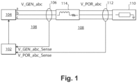
- FIG. 1 a partial view of an embodiment of a system in accordance with the disclosure is shown in Fig. 1 and is designated generally by reference character 100.
- FIGs. 2-5 Other embodiments of systems in accordance with the disclosure, or aspects thereof, are provided in Figs. 2-5 , as will be described.
- the systems and methods described herein can be used to quickly determine a fault and accommodate using minimal resources.
- a system 100 comprises a generator control unit (GCU) 102 that can be configured to control a generator 104.
- the generator 104 can be operatively connected to the GCU 102 to be controlled by the GCU 102, and the feeder 108 can be connected to the generator 104 to supply power from the generator 104 to a load 110.
- the system 100 can include a first sensor 106 connected to a feeder 108 to provide feedback to the GCU 102 for generator control.
- the first sensor 106 can be configured to sense at least one of voltage and/or current in the feeder 108, the feeder 108 connecting between the generator 104 and the load 110.
- the system 100 can also include a second sensor 112 connected to the feeder 108 to provide feedback to the GCU 102 for generator control.
- the second sensor 112 can also be configured to sense at least one of voltage and/or current in the feeder 108.
- the first and second sensors 106,112 can be configured to connect to the feeder 108 separated by a feeder impedance 114.
- the first sensor and second sensors 106, 112 each can be configured to sense at least one of voltage and/or current in each one of three phases, a,b,c, of respective portions of the feeder 108.
- the first sensor 106 can be electrically closer to the generator 104 than to the load 110 end of the feeder 108 than the second sensor 112 relative to the feeder impedance 114.
- the system 100 can also include logic in the GCU 102.
- the logic can include machine readable instructions, digital circuitry, analog circuitry, any combination of thereof, and/or any other suitable form of logic.
- the logic can be configured to cause the GCU 102 to use feedback from the first and second sensors 106,112 to control the generator 104.
- the logic can be configured to detect faults in each of the first and second sensors 106,112, and even if a fault is detected, the logic can continue operation of the generator 104.
- the logic can be configured to cause the GCU 102 to detect a discrepancy between the first and second sensors 106,112 and decide whether the first sensor 106 is at fault or whether the second sensor 112 is at fault. After detection and determination of which sensor has faulted, the logic can then control the generator 104 based on feedback from whichever of the first or second sensors 106,112 are not at fault. This process will be described in more detail below.
- Fig. 2 feedback from the first sensor 106 is represented by V_GEN_abc_Sense, and feedback from the second sensor 112 is represented by V_POR_abc_Sense.
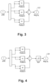
- the logic can then calculate the sum voltage/current magnitude or the voltage/current magnitude square for each of V_POR_abc_Sense and V_GEN_abc_Sense using either of the methods shown in Figs. 3-4 .
- Fig. 3 shows a method for calculating a magnitude squared
- Fig. 4 shows a method for calculating a magnitude
- Figure 5 shows an alternative method for calculating either a magnitude and/or a magnitude squared. While Fig. 5 shows a square root step, it should be appreciated that this step is optional if a magnitude is desired over a magnitude squared.
- the logic can then compare the summed magnitudes or magnitudes squared 120,122 of voltage and/or current sensed for each of three phases a,b,c of the feeder 108 for each of the first and second sensor 106,112 versus a respective threshold [e.g. V_OSF_TH and -V_OSF_TH] for each of VPOR_OSF (voltage open sense failure at the point of regulation for the second sensor) and VGEN_OSF (voltage open sense failure at the point of the first sensor), e.g. using a comparator 124.
- V_OSF_TH and -V_OSF_TH for each of VPOR_OSF (voltage open sense failure at the point of regulation for the second sensor) and VGEN_OSF (voltage open sense failure at the point of the first sensor
- VPOR_OSF can represent logic for comparing the V_OSF_Th threshold to the summed magnitudes or magnitudes squared 120,122 of voltage and/or current sensed for each of three phases a,b,c of the feeder 108 for each of the first and second sensor 106,112.
- VGEN_OSF can represent logic for comparing the -V_OSF_Th threshold to the summed magnitudes or magnitudes squared 120,112 of voltage and/or current sensed for each of three phases a,b,c of the feeder 108 for each of the first and second sensor 106,112.
- each of the VPOR_OSF and VGEN_OSF can connect through a respective latch 116 to a respective switch 118.
- the latch 116 latch can be disposed within each branch of the logic diagram as shown, so that the latch 116 can suppress a faulted sense. Once a sense has passed through latch 116, the latch 116 must be reset to resume normal two sense operation. If a fault is detected in either branch, the switches 118 can then switch off faulty feedback from the respective one of the first and second sensors 106,112 to the GCU 102.
- the logic can include transforming three phases from each of the first and second sensors 106,112 to Alpha-Beta coordinates, and then taking the magnitude of the Alpha-Beta for each, for example as shown in Fig. 5 .
- the system 100 can include filtering when deciding which of the first and/or second sensors 106,112 is experiencing fault.
- the system can filter based on whether the difference of magnitudes 120 (or magnitudes squared 122) exceeds a threshold a certain number of consecutive times.
- the filter can be a difference of magnitudes 120 (or magnitudes squared 122) is processed through an infinite impulse response (IIR) filter, for example a low pass filter.
- IIR infinite impulse response
- FIR finite impulse response
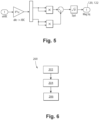
- a method 200 can comprise, at box 202, using feedback from first and second sensors 106,112 spaced apart along a feeder 108 to control a generator 104 powering a load 110 through the feeder 108.
- the method 200 can also include, at box 204, detecting a fault in one of the first and second sensors 106, 112 and continuing operation of the generator 104.
- the method 200 can include filtering when detecting a fault in one of the sensors 106,112 and deciding which sensor 106,112 is at fault, as shown at box 206.
Landscapes
- Engineering & Computer Science (AREA)
- Power Engineering (AREA)
- Control Of Eletrric Generators (AREA)
- Testing Electric Properties And Detecting Electric Faults (AREA)
- Physics & Mathematics (AREA)
- Computer Hardware Design (AREA)
- Mathematical Physics (AREA)
- Dc-Dc Converters (AREA)
- Testing Of Short-Circuits, Discontinuities, Leakage, Or Incorrect Line Connections (AREA)
Applications Claiming Priority (2)
| Application Number | Priority Date | Filing Date | Title |
|---|---|---|---|
| US17/141,012 US12034396B2 (en) | 2021-01-04 | 2021-01-04 | Fast POR trim correction |
| EP22150102.6A EP4024696B1 (de) | 2021-01-04 | 2022-01-04 | Schnelle por-trimmkorrektur und verfahren |
Related Parent Applications (1)
| Application Number | Title | Priority Date | Filing Date |
|---|---|---|---|
| EP22150102.6A Division EP4024696B1 (de) | 2021-01-04 | 2022-01-04 | Schnelle por-trimmkorrektur und verfahren |
Publications (2)
| Publication Number | Publication Date |
|---|---|
| EP4383493A2 true EP4383493A2 (de) | 2024-06-12 |
| EP4383493A3 EP4383493A3 (de) | 2024-09-04 |
Family
ID=79230591
Family Applications (2)
| Application Number | Title | Priority Date | Filing Date |
|---|---|---|---|
| EP24172712.2A Pending EP4383493A3 (de) | 2021-01-04 | 2022-01-04 | Schnelle por-trimmkorrektur |
| EP22150102.6A Active EP4024696B1 (de) | 2021-01-04 | 2022-01-04 | Schnelle por-trimmkorrektur und verfahren |
Family Applications After (1)
| Application Number | Title | Priority Date | Filing Date |
|---|---|---|---|
| EP22150102.6A Active EP4024696B1 (de) | 2021-01-04 | 2022-01-04 | Schnelle por-trimmkorrektur und verfahren |
Country Status (2)
| Country | Link |
|---|---|
| US (1) | US12034396B2 (de) |
| EP (2) | EP4383493A3 (de) |
Family Cites Families (13)
| Publication number | Priority date | Publication date | Assignee | Title |
|---|---|---|---|---|
| US5488532A (en) * | 1993-10-27 | 1996-01-30 | Sundstrand Corporation | System of protection for electric power distribution failures |
| US6377086B1 (en) | 1999-10-05 | 2002-04-23 | Agere Systems Guardian Corp. | Low power dual-voltage sense circuit buffer |
| KR100394757B1 (ko) | 2000-09-21 | 2003-08-14 | 가부시끼가이샤 도시바 | 반도체 장치 |
| US6504486B1 (en) | 2000-11-06 | 2003-01-07 | Sun Microsystems, Inc. | Dual voltage sense cell for input/output dynamic termination logic |
| US6353568B1 (en) | 2000-12-29 | 2002-03-05 | Lsi Logic Corporation | Dual threshold voltage sense amplifier |
| US6815983B2 (en) | 2003-01-28 | 2004-11-09 | Xicor, Inc. | Analog floating gate voltage sense during dual conduction programming |
| US8861147B2 (en) | 2012-04-25 | 2014-10-14 | The Boeing Company | Fault protection for aircraft power systems |
| CN205263697U (zh) | 2015-12-30 | 2016-05-25 | 广西师范大学 | 一种带上电复位的可校正低功耗电压基准源 |
| CN105425887B (zh) | 2015-12-30 | 2017-04-05 | 广西师范大学 | 一种带上电复位的可校正低功耗电压基准源 |
| US10613604B2 (en) | 2016-12-22 | 2020-04-07 | Texas Instruments Incorporated | On chip power on reset with integrated supervisory functions for a functional safety system |
| EP3379273B1 (de) * | 2017-03-22 | 2019-09-18 | Siemens Aktiengesellschaft | Verfahren, einrichtung und system zum ermitteln des fehlerortes eines fehlers auf einer leitung eines elektrischen energieversorgungsnetzes |
| JP7117904B2 (ja) | 2018-06-11 | 2022-08-15 | 三菱電機株式会社 | 電力用半導体装置 |
| US10965125B2 (en) * | 2018-07-11 | 2021-03-30 | The Boeing Company | Simultaneous bidirectional power usage of generator power feeders |
-
2021
- 2021-01-04 US US17/141,012 patent/US12034396B2/en active Active
-
2022
- 2022-01-04 EP EP24172712.2A patent/EP4383493A3/de active Pending
- 2022-01-04 EP EP22150102.6A patent/EP4024696B1/de active Active
Also Published As
| Publication number | Publication date |
|---|---|
| US12034396B2 (en) | 2024-07-09 |
| EP4383493A3 (de) | 2024-09-04 |
| EP4024696B1 (de) | 2024-05-22 |
| US20220216815A1 (en) | 2022-07-07 |
| EP4024696A1 (de) | 2022-07-06 |
Similar Documents
| Publication | Publication Date | Title |
|---|---|---|
| CN106253242B (zh) | 电力推进系统中的故障识别和隔离 | |
| US10714288B2 (en) | Relay device | |
| JP6105705B2 (ja) | 系統連系用リレーの異常検出装置、及びパワーコンディショナ | |
| US7619866B2 (en) | Electric trip device provided with monitoring means, circuit breaker comprising one such trip device and method of monitoring | |
| CN103229063A (zh) | 接地检测装置、接地检测方法、太阳能发电系统以及接地检测程序 | |
| US20190140438A1 (en) | Fuse system for at least one load of a vehicle | |
| KR20190076743A (ko) | 선박용 배터리시스템 및 그 운용방법 | |
| EP4383493A2 (de) | Schnelle por-trimmkorrektur | |
| CN112462303B (zh) | 一种电网电流传感器的连接识别检测方法 | |
| US11834193B2 (en) | Dual pole switch detection circuit | |
| WO2017102692A1 (en) | Ground fault detection and interrupt system | |
| JP2004132937A (ja) | 電圧検出器の異常検出方法 | |
| US20120098345A1 (en) | Minimal interruption dc power supply | |
| CN115051461B (zh) | 供电线路控制装置及ups系统 | |
| EP2595268B1 (de) | Gleichstromversorgung mit minimaler Unterbrechung | |
| CN114942383B (zh) | 并网开关的故障检测方法及系统 | |
| EP0887628A1 (de) | Sicherheitseinrichtung | |
| EP2651026A2 (de) | Automatische Fehlerisolierungsmethodologie | |
| US20220360070A1 (en) | Protection apparatus for a driver circuit, and method for protecting a driver circuit | |
| CN100582797C (zh) | 用于识别故障相的方法与系统 | |
| JP5367444B2 (ja) | 電気車制御装置及びその試験方法 | |
| JPH08103036A (ja) | 瞬時電圧低下対策装置 | |
| CN103904773A (zh) | 配电设备的旁路装置和配电网络的控制方法 | |
| EP4339625A1 (de) | Verbesserungen an oder im zusammenhang mit sensoren zur verwendung in hvdc-stromübertragungsnetzen | |
| JP3794208B2 (ja) | 系統連系システムの保護装置 |
Legal Events
| Date | Code | Title | Description |
|---|---|---|---|
| PUAI | Public reference made under article 153(3) epc to a published international application that has entered the european phase |
Free format text: ORIGINAL CODE: 0009012 |
|
| STAA | Information on the status of an ep patent application or granted ep patent |
Free format text: STATUS: THE APPLICATION HAS BEEN PUBLISHED |
|
| AC | Divisional application: reference to earlier application |
Ref document number: 4024696 Country of ref document: EP Kind code of ref document: P |
|
| AK | Designated contracting states |
Kind code of ref document: A2 Designated state(s): AL AT BE BG CH CY CZ DE DK EE ES FI FR GB GR HR HU IE IS IT LI LT LU LV MC MK MT NL NO PL PT RO RS SE SI SK SM TR |
|
| REG | Reference to a national code |
Ref country code: DE Ref legal event code: R079 Free format text: PREVIOUS MAIN CLASS: H02H0007060000 Ipc: H02P0009000000 |
|
| PUAL | Search report despatched |
Free format text: ORIGINAL CODE: 0009013 |
|
| RIN1 | Information on inventor provided before grant (corrected) |
Inventor name: YOUNG,SHAWN J. Inventor name: MISKOVIC, VLATKO Inventor name: HASSEMAN, MATTHEW RYAN Inventor name: SCHMITT,DWIGHT D. |
|
| AK | Designated contracting states |
Kind code of ref document: A3 Designated state(s): AL AT BE BG CH CY CZ DE DK EE ES FI FR GB GR HR HU IE IS IT LI LT LU LV MC MK MT NL NO PL PT RO RS SE SI SK SM TR |
|
| RIC1 | Information provided on ipc code assigned before grant |
Ipc: H02H 7/06 20060101ALI20240730BHEP Ipc: H02P 9/00 20060101AFI20240730BHEP |
|
| STAA | Information on the status of an ep patent application or granted ep patent |
Free format text: STATUS: REQUEST FOR EXAMINATION WAS MADE |
|
| 17P | Request for examination filed |
Effective date: 20250303 |
|
| STAA | Information on the status of an ep patent application or granted ep patent |
Free format text: STATUS: EXAMINATION IS IN PROGRESS |
|
| 17Q | First examination report despatched |
Effective date: 20260213 |