EP4383475A1 - Connector unit - Google Patents
Connector unit Download PDFInfo
- Publication number
- EP4383475A1 EP4383475A1 EP22852613.3A EP22852613A EP4383475A1 EP 4383475 A1 EP4383475 A1 EP 4383475A1 EP 22852613 A EP22852613 A EP 22852613A EP 4383475 A1 EP4383475 A1 EP 4383475A1
- Authority
- EP
- European Patent Office
- Prior art keywords
- connector
- cap
- connector housing
- holes
- opening portion
- Prior art date
- Legal status (The legal status is an assumption and is not a legal conclusion. Google has not performed a legal analysis and makes no representation as to the accuracy of the status listed.)
- Granted
Links
Images


Classifications
-
- H—ELECTRICITY
- H01—ELECTRIC ELEMENTS
- H01R—ELECTRICALLY-CONDUCTIVE CONNECTIONS; STRUCTURAL ASSOCIATIONS OF A PLURALITY OF MUTUALLY-INSULATED ELECTRICAL CONNECTING ELEMENTS; COUPLING DEVICES; CURRENT COLLECTORS
- H01R13/00—Details of coupling devices of the kinds covered by groups H01R12/70 or H01R24/00 - H01R33/00
- H01R13/44—Means for preventing access to live contacts
- H01R13/447—Shutter or cover plate
-
- H—ELECTRICITY
- H01—ELECTRIC ELEMENTS
- H01R—ELECTRICALLY-CONDUCTIVE CONNECTIONS; STRUCTURAL ASSOCIATIONS OF A PLURALITY OF MUTUALLY-INSULATED ELECTRICAL CONNECTING ELEMENTS; COUPLING DEVICES; CURRENT COLLECTORS
- H01R13/00—Details of coupling devices of the kinds covered by groups H01R12/70 or H01R24/00 - H01R33/00
- H01R13/46—Bases; Cases
- H01R13/52—Dustproof, splashproof, drip-proof, waterproof, or flameproof cases
- H01R13/5213—Covers
-
- H—ELECTRICITY
- H01—ELECTRIC ELEMENTS
- H01R—ELECTRICALLY-CONDUCTIVE CONNECTIONS; STRUCTURAL ASSOCIATIONS OF A PLURALITY OF MUTUALLY-INSULATED ELECTRICAL CONNECTING ELEMENTS; COUPLING DEVICES; CURRENT COLLECTORS
- H01R13/00—Details of coupling devices of the kinds covered by groups H01R12/70 or H01R24/00 - H01R33/00
- H01R13/46—Bases; Cases
- H01R13/52—Dustproof, splashproof, drip-proof, waterproof, or flameproof cases
- H01R13/5227—Dustproof, splashproof, drip-proof, waterproof, or flameproof cases with evacuation of penetrating liquids
Definitions
- the present invention relates to a connector unit, particularly to a connector unit in which an opening portion is openably and closably covered by a cap, the opening portion allowing a counter connector to be inserted therein in a fitting process.
- the connector unit capable of discharging, to the outside thereof, water that has entered through an opening portion which allows a counter connector to be inserted therein has been disclosed in, for example, Patent Literature 1.
- the connector unit is provided with a connector housing 1 formed of an insulating resin, and the connector housing 1 includes a housing body portion 2 of cuboid shape and a front plate portion 3 of rectangular shape formed at a front end of the housing body portion 2.
- the front plate portion 3 is provided with an opening portion 4, and in a fitting process with a counter connector, the counter connector is inserted into the opening portion 4 along a fitting axis and fitted with a connector portion (not shown) disposed inside the housing body portion 2.
- the opening portion 4 has an oval shape elongated in a predetermined direction, and a back part of the front plate portion 3 is provided with drain passages 5 to 8 extending from opposite ends in the predetermined direction of the opening portion 4 to edges of the front plate portion 3.
- Patent Literature 1 JP 2019-204598 A
- drain passages 5 to 8 extend from the opposite ends of the opening portion 4 to the edges of the front plate portion 3, even when the connector unit is disposed in such a position that the opening portion 4 extends in a horizontal direction or a vertical direction, water that has entered the connector housing 1 through the opening portion 4 can be discharged to the outside of the connector housing 1 through at least one of the drain passages 5 to 8.
- a cap that openably and closably covers the opening portion 4.
- the cap is preferably attached by use of an attachment hole formed in a part of the front plate portion 3 on the upper side from the opening portion 4, depending on the position in which the connector unit is disposed.
- a large number of attachment holes are formed in the front plate portion 3 in preparation for both the case where the connector unit is disposed in such a position that the long sides of the front plate portion 3 extend in a horizontal direction and the case where the connector unit is disposed in such a position that the long sides of the front plate portion 3 extend in a vertical direction; however, there is a problem in that the structure of the connector unit becomes complicated because it is necessary to form a large number of drain passages 5 to 8 and a large number of attachment holes in order to discharge water and attach the cap.
- the present invention has been made to overcome the conventional problem described above and aims at providing a connector unit in which an opening portion of a connector housing is openably and closably covered by a cap and which is capable of discharging water that has entered the connector housing through the opening portion while having a simple structure.
- a connector unit according to the present invention is one in which an opening portion for inserting a counter connector is openably and closably covered by a cap, the connector unit comprising:
- the connector housing may include four through-holes as the two or more through-holes each penetrating the front plate portion and communicating with the inside of the connector housing,
- the connector housing has a drain guide surface connected to the through-hole situated on the lower side from the opening portion and inclined downward toward an outside of the connector housing when the connector unit is disposed.
- the cap includes a lid portion having a back surface facing the front plate portion, and a L-shaped arm joined to the lid portion and made of an elastic material,
- a connector housing includes a front plate portion that is provided with an opening portion and two or more through-holes penetrating the front plate portion and communicating with the inside of the connector housing, two through-holes of the two or more through-holes are separately disposed at positions of two vertexes, opposed to each other, of a rectangular surrounding the opening portion in the front plate portion, and when the connector unit is disposed, one of the two through-holes is situated on an upper side from the opening portion and serves as a cap attachment hole for attaching a cap to the connector housing, and another of two through-holes is situated on a lower side from the opening portion and serves as a drain hole for the connector housing.
- a mounting position of the connector unit is not limited to one direction, and in the connector unit, the opening portion of the connector housing can be openably and closably covered by the cap, and water that has entered the connector housing through the opening portion can be discharged while the connector unit has a simple structure.
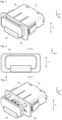
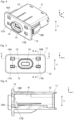
- FIGS. 1 and 2 are a perspective view and a front view, respectively, each showing a connector unit according to Embodiment 1.
- the connector unit includes a connector housing 11 made of an insulating material such as an insulating resin and a cap 21 attached to a front part of the connector housing 11 and made of an elastic material such as ethylene propylene diene rubber (EPDM).
- EPDM ethylene propylene diene rubber
- the connector housing 11 includes a housing body portion 12 having a substantially cuboid shape and a front plate portion 13 of rectangular shape formed at a front edge of the housing body portion 12, and the cap 21 is disposed so as to cover the front plate portion 13 of the connector housing 11.
- X direction the direction in which the long side of the front plate portion 13 extends along a surface of the front plate portion 13
- +Y direction the direction which is orthogonal to the X direction and extends from the front part of the connector housing 11, where the front plate portion 13 is provided, to a back part of the connector housing 11
- Z direction the direction perpendicular to an XY plane
- the connector unit shown in FIGS. 1 and 2 is disposed in a first position in which the +Z direction is directed upward along a vertical direction V
- the X direction in which the long side of the front plate portion 13 extends is directed to a horizontal direction.
- the cap 21 is movably attached to the connector housing 11 and can be drawn in the -Y direction from the connector housing 11.
- the front plate portion 13 of the connector 11 is provided at a substantially central portion thereof with an opening portion 14 which opens in the fitting direction of fitting with a counter connector (not shown) and in which the counter connector is inserted in a fitting process with the counter connector.
- a counter connector for example, a universal serial bus (USB) connector can be used, and the counter connector is inserted into the opening portion 14 of the front plate portion 13 from the -Y direction toward the +Y direction.
- USB universal serial bus
- a protrusion portion 15 extending in an XZ plane so as to form an oval frame surrounding the opening portion 14 and protruding in the -Y direction.
- the front plate portion 13 is provided with a pair of through-holes 16A and 16B penetrating the front plate portion 13.
- the front plate portion 13 is provided with a pair of through-holes 17A and 17B penetrating the front plate portion 13.
- the pair of through-holes 16A and 16B at the positions shifted in the +Z direction from the opening portion 14 and the pair of through-holes 17A and 17B at the positions shifted in the -Z direction from the opening portion 14 are positioned at four vertexes of a rectangular S surrounding the opening portion 14 and having a pair of long sides extending in the X direction and a pair of short sides extending in the Z direction.
- each of the pair of through-holes 16A and 16B on the +Z direction side functions as a cap attachment hole for attaching the cap 21 to the connector housing 11, while each of the pair of through-holes 17A and 17B on the -Z direction side functions as a drain hole for discharging water that has entered the connector housing 11 through the opening portion 14.
- the through-hole 16A, situated on the -X direction side, of the pair of through-holes 16A and 16B each serving as the cap attachment hole and the through-hole 17B, situated on the +X direction side, of the pair of through-holes 17A and 17B each serving as the drain hole are respectively positioned at two vertexes situated on one of two diagonal lines of the rectangular S, while the through-hole 16B, situated on the +X direction side, of the pair of through-holes 16A and 16B each serving as the cap attachment hole and the through-hole 17A, situated on the -X direction side, of the pair of through-holes 17A and 17B each serving as the drain hole are respectively positioned at two vertexes situated on the other of the two diagonal lines of the rectangular S.
- the housing body portion 12 has a drain guide surface 18A that is connected to the through-hole 17B disposed on the -Z direction side to function as the drain hole and that is inclined downward and toward the outside of the connector housing 11 when the connector unit is disposed in the first position.
- the drain guide surface 18A is inclined so as to be positioned farther in the -Z direction as advancing toward the -Y direction.
- the drain guide surface 18A inclined so as to be positioned farther in the -Z direction as advancing toward the -Y direction is connected also to the through-hole 17A situated on the -X direction side from the through-hole 17B.
- the drain guide surface 18A as above is connected to each of the through-holes 17A and 17B, even when water has entered the connector housing 11 through the opening portion 14 of the connector unit disposed in the first position, the water can be guided by the drain guide surface 18A and easily discharged from the through-holes 17A and 17B to the outside of the connector housing 11.
- drain guide surfaces 18B are separately connected to the through-holes 16A and 16B.
- One drain guide surface 18B connected to the through-hole 16A, situated on the -X direction side, of the through-holes 16A and 16B is inclined so as to be positioned farther in the -X direction as advancing toward the -Y direction, while the other drain guide surface 18B connected to the through-hole 16B, situated on the +X direction side, is inclined to be positioned farther in the +X direction as advancing toward the -Y direction.
- These drain guide surfaces 18B are configured to guide water that has entered the connector housing 11 to be discharged when the connector unit is disposed not in the first position but, for example, in a second position in which the X direction is directed to the vertical direction V
- the same drain guide surfaces 18B are separately connected also to the through-holes 17A and 17B situated on the -Z direction side from the through-holes 16A and 16B.
- one drain guide surface 18B connected to the through-hole 17A, situated on the -X direction side, of the through-holes 17A and 17B is inclined so as to be positioned farther in the -X direction as advancing toward the -Y direction
- the other drain guide surface 18B connected to the through-hole 17B, situated on the +X direction side is inclined to be positioned farther in the +X direction as advancing toward the -Y direction.
- the cap 21 includes a lid portion 22 of rectangular and substantially flat plate shape extending along an XZ plane and a pair of L-shaped arms 23 joined to the lid portion 22 and extending in the +Y direction.
- the pair of L-shaped arms 23 correspond to the pair of through-holes 16A and 16B formed in the front plate portion 13 of the connector housing 11.
- a -Z directional end of the lid portion 22 is provided with a handle portion 22A for moving the cap 21.
- Each of the pair of L-shaped arms 23 includes a support portion 25 of rod shape projecting and extending in the +Y direction from a back surface of the lid portion 22 at a position shifted in the +Z direction in the back surface facing in the +Y direction, a bent portion 26 formed at a +Y directional end of the support portion 25, and a hook portion 27 of rod shape extending in the -Z direction from the bent portion 26.
- the bent portion 26 is a connection portion between the support portion 25 and the hook portion 27 intersecting orthogonally to each other, and has a corner portion sharply pointed in the +Y direction and the +Z direction.
- the bent portion 26 is provided with a cutout 28 disposed at a middle part of the bent portion 26 in the X direction and extending along a YZ plane, and due to the presence of this cutout 28, thin-wall parts are formed in the bent portion 26. While the cap 21 is made of an elastic material, the bent portion 26 has the thin-wall portions so as to be elastically deformed more easily.
- a fitting recessed portion of oval shape is formed to correspond to the protrusion portion 15 formed on the front plate portion 13 of the connector housing 11, and it is configured such that when the protrusion portion 15 of the connector housing 11 is fitted into this fitting recessed portion, the cap 21 is fixed to the front plate portion 13, and when the cap 21 is fixed, there is a gap between the cap 21 and the front plate portion 13, and water can be discharged even when the cap 21 is fixed.
- one L-shaped arm 23, situated on the +X direction side, of the pair of L-shaped arms 23 of the cap 21 is passed through the through-hole 16B of the connector housing 11, and similarly, the other L-shaped arm 23, situated on the -X direction side, of the pair of L-shaped arms 23 of the cap 21 is passed through the through-hole 16A of the connector housing 11.
- the cap 21 is retained by the connector housing 11 with the hook portions 27 of the pair of L-shaped arms 23 being accommodated in an inner space R of the housing body portion 12 and the support portions 25 being separately passed through the through-holes 16A and 16B.
- a connector portion C1 to be fitted with a counter connector (not shown) along a Y axis and other components are incorporated in the inner space R of the housing body portion 12.
- the support portion 25 and the hook portion 27 respectively have thickness dimensions D1 and D2 smaller than a dimension H1 of the through-hole 16A, 16B serving as the cap attachment hole of the front plate portion 13.
- the support portion 25 and the hook portion 27 of the L-shaped arm 23 can be moved in the Y direction smoothly when these portions are passed through the through-hole 16A, 16B.
- the bent portion 26 of the L-shaped arm 23 has a maximum dimension D3 larger than the dimension H1 of the through-hole 16A, 16B.
- the maximum dimension D3 of the bent portion 26 shown in FIG. 10 is represented by a distance from a connection portion between a -Z directional edge of the support portion 25 and a -Y directional edge of the hook portion 27 up to the corner portion, sharply pointed in the +Y direction and the +Z direction, of the bent portion 26.
- a maximum value of a cross-sectional area when the bent portion 26 is cut by a cross section perpendicular to a YZ plane including the support portion 25, the bent portion 26, and the hook portion 27 is a value larger than the area of the through-hole 16A, 16B.
- the cap 21 does not easily come out of the through-hole 16A, 16B even when a force to move the L-shaped arm 23 in the -Y direction with respect to the front plate portion 13 and pull out the L-shaped arm 23 from the through-hole 16A, 16B acts on the cap 21.
- the hook portion 27 of the L-shaped arm 23 has a length dimension L1 larger than the dimension H1 of the through-hole 16A, 16B. Therefore, when the L-shaped arm 23 is moved in the -Y direction with respect to the front plate portion 13, the hook portion 27 makes contact with and hooked by the back surface, facing in the +Y direction, of the front plate portion 13, whereby the L-shaped arm 23 cannot be easily pulled out from the through-hole 16A, 16B.
- tips of the hook portions 27 of the pair of L-shaped arms 23 of the cap 21 are separately passed through and inserted into the through-holes 16A and 16B of the front plate portion 13 in the +Y direction, and thereafter, the bent portions 26 of the pair of L-shaped arms 23 are separately inserted into the through-holes 16A and 16B while being elastically deformed and squashed by an operator's finger or the like.
- the bent portions 26 are formed to be easily elastically deformed, so that the bent portions 26 can be easily squashed and inserted into the through-holes 16A, 16B, respectively.
- the pair of L-shaped arms 23 are moved in the +Y direction, and the protrusion portion 15 of the front plate portion 13 is fitted into the fitting recessed portion of the lid portion 22, whereby the cap 21 is fixed to the connector housing 11.
- the cap 21 is drawn from the connector housing 11 until the hook portions 27 of the pair of L-shaped arms 23 of the cap 21 make contact with and are hooked by the front plate portion 13 of the connector housing 11, and in this state, the lid portion 22 of the cap 21 is turned up in the +Z direction, and the counter connector (not shown) is inserted from the -Y direction to the +Y direction through the opening portion 14 of the front plate portion 13 exposed toward the -Y direction to thereby be fitted with the connector portion C1.
- the cap 21 openably and closably covers the opening portion 14 of the connector unit disposed in the first position, and the lid portion 22 of the cap 21 is turned up, so that a counter connector can be fitted, and the cap 21 can be prevented from coming off the connector housing 11.
- FIG. 11 shows the connector unit disposed in a second position in which the X direction, in which the long side of the front plate portion 13 of the connector housing 11 extends, is directed to the vertical direction V.
- the connector unit is disposed such that the +X direction is directed upward along the vertical direction V
- the connector unit includes the connector housing 11 and a cap 31 attached to the front part of the connector housing 11.
- the connector housing 11 is rotated from the position of the connector housing 11 shown in FIG. 4 by 90 degrees around the Y axis, and the cap 31 is different from the cap 21 used in the case of the first position and is a dedicated cap for the second position.
- the connector housing 11 is commonly used, and either of the cap 21 and the cap 31 is used depending on the first position and the second position.
- the cap 31 is movably attached to the connector housing 11 and can be drawn in the -Y direction from the connector housing 11.
- the cap 31 is made of an elastic material such as EPDM and includes a lid portion 32 of rectangular and substantially flat plate shape elongated in the X direction along an XZ plane and a pair of L-shaped arms 33 joined to the lid portion 32 and extending in the +Y direction.
- the connector unit is disposed such that the +X direction is directed upward along the vertical direction V, of the four through-holes 16A, 16B, 17A, 17B formed in the front plate portion 13 of the connector housing 11, the through-holes 16B and 17B disposed on the +X direction side each function as the cap attachment hole, and the through-holes 16A and 17A disposed on the -X direction side each function as the drain hole.
- the pair of L-shaped arms 33 of the cap 31 are separately inserted in the through-holes 16B and 17B each serving as the cap attachment hole.
- FIG. 13 shows the connector housing 11 in the second position.
- the through-holes 16B and 17B each serving as the cap attachment hole is situated on the upper side in the vertical direction V from the opening portion 14, while the through-holes 16A and 17A each serving as the drain hole is situated on the lower side in the vertical direction V from the opening portion 14.
- the through-holes 16B and 17B situated on the upper side in the vertical direction V and the through-holes 16A and 17A situated on the lower side in the vertical direction V are positioned at the four vertexes of the rectangular S surrounding the opening portion 14.
- the L-shaped arm 33, situated on the -Z direction side, of the pair of L-shaped arms 33 of the cap 31 is passed through the through-hole 17B of the connector housing 11, and similarly, the L-shaped arm 33, situated on the +Z direction side, of the pair of L-shaped arms 33 of the cap 31 is passed through the through-hole 16B of the connector housing 11.
- the L-shaped arm 33 includes a support portion 35 of rod shape projecting and extending in the +Y direction from a back surface of the lid portion 32 at a position shifted in the +X direction in the back surface facing in the +Y direction, a bent portion 36 formed at a +Y directional end of the support portion 35, and a hook portion 37 of rod shape extending in the -X direction from the bent portion 36.
- the cap 31 is retained by the connector housing 11 with the hook portions 37 of the pair of L-shaped arms 33 being accommodated in the inner space R of the housing body portion 12 and the support portions 35 being separately passed through the through-holes 16B and 17B.
- the support portion 35 and the hook portion 37 each have a thickness dimension smaller than the dimension of the through-hole 16B, 17B serving as the cap attachment hole of the front plate portion 13, and the bent portion 36 has a maximum dimension larger than the dimension of the through-hole 16A, 16B.
- the cap 31 openably and closably covers the opening portion 14 of the connector unit disposed in the second position, and the lid portion 32 of the cap 31 is turned up, so that a counter connector can be fitted, and the cap 31 can be prevented from coming off the connector housing 11.
- the cap 21 used in the connector unit disposed in the first position is retained by the connector housing 11 by the pair of L-shaped arms 23, and the cap 31 used in the connector unit disposed in the second position is also retained by the connector housing 11 by the pair of L-shaped arms 33, but the invention is not limited thereto.
- a cap can be retained by only one L-shaped arm.
- FIG. 16 shows a connector unit according to Embodiment 2.
- the connector unit includes a connector housing 41 made of an insulating material such as an insulating resin and a cap 51 attached to a front part of the connector housing 41 and made of an elastic material such as EPDM.
- FIG. 16 shows the state where the cap 51 is drawn from the connector housing 41.
- the connector unit shown in FIG. 16 is disposed in a first position in which the +Z direction is directed upward along the vertical direction V
- the connector housing 41 includes a housing body portion 42 having a substantially cuboid shape and a front plate portion 43 of rectangular shape formed at a front edge of the housing body portion 42, and as shown in FIG. 17 , the front plate portion 43 is provided at a substantially central portion thereof with an opening portion 44 in which a counter connector (not shown) is inserted in a fitting process with the counter connector, while at a periphery of the opening portion 44, provided is a protrusion portion 45 extending in an XZ plane so as to form an oval frame surrounding the opening portion 44 and protruding in the -Y direction.
- the front plate portion 43 is provided with a through-hole 46A penetrating the front plate portion 43, and on the +X direction side of the opening portion 44 and at a position shifted in the -Z direction from the opening portion 44, the front plate portion 43 is provided with a through-hole 47B penetrating the front plate portion 43.
- the through-holes 46A and 47B are positioned at two vertexes situated on one diagonal line of a rectangular S surrounding the opening portion 44 and having a pair of long sides extending in the X direction and a pair of short sides extending in the Z direction.
- the through-hole 46A situated on the +Z direction side from the opening portion 44 functions as a cap attachment hole for attaching the cap 51 to the connector housing 41
- the through-hole 47B situated on the -Z direction side from the opening portion 44 functions as a drain hole for discharging water that has entered the connector housing 41 through the opening portion 44.
- the connector housing 41 has the front plate portion 43 provided with the only two through-holes 46A and 47B in place of the front plate portion 13 provided with the four through-holes 16A, 16B, 17A and 17B as shown in FIG. 5 in the connector housing 11 used in Embodiment 1, and the remaining configuration of the front plate portion 43 and the configuration of the housing body portion 42 are the same as those in the connector housing 11.
- the cap 51 includes a lid portion 52 of rectangular and substantially flat plate shape elongated in the X direction along an XZ plane and one L-shaped arm 53 projecting and extending in the +Y direction from a back surface of the lid portion 52a at a position shifted in the -X direction and the +Z direction in the back surface facing in the +Y direction.
- the L-shaped arm 53 has the same configuration as that of the L-shaped arm 23 of the cap 21 used in Embodiment 1 and shown in FIG. 8 and includes a support portion of rod shape projecting and extending in the +Y direction from the back surface of the lid portion 52, a bent portion formed at a +Y directional end of the support portion, and a hook portion of rod shape extending in the -Z direction from the bent portion.
- the L-shaped arm 53 is inserted in the through-hole 46A serving as the cap attachment hole, and the cap 51 is retained by the connector housing 41 with the hook portion of the L-shaped arm 53 being accommodated inside the housing body portion 42 and the support portion being passed through the through-hole 46A.
- the cap 51 has the only one L-shaped arm 53, the cap 51 openably and closably covers the opening portion 44 of the connector unit disposed in the first position, and the lid portion 52 of the cap 51 is turned up, so that a counter connector can be fitted, and the cap 51 can be prevented from coming off the connector housing 41.
- FIG. 19 shows the connector unit disposed in a second position in which the X direction, in which the long side of the front plate portion 43 of the connector housing 41 extends, is directed to the vertical direction V.
- the connector unit is disposed such that the +X direction is directed upward along the vertical direction V.
- the connector unit includes the connector housing 41 and a cap 61 attached to the front part of the connector housing 41.
- the connector housing 41 is rotated from the position of the connector housing 41 shown in FIG. 17 by 90 degrees around the Y axis, and the cap 61 is different from the cap 51 used in the case of the first position and is a dedicated cap for the second position.
- the connector housing 41 is commonly used, and either of the cap 51 and the cap 61 is used depending on the first position and the second position.
- the through-hole 47B is situated on the +Z direction side from the opening portion 44 and functions as a cap attachment hole for attaching the cap 61 to the connector housing 41
- the through-hole 46A is situated on the -Z direction side from the opening portion 44 and functions as a drain hole for discharging water that has entered the connector housing 41 through the opening portion 44.
- the cap 61 is movably attached to the connector housing 41 and can be drawn in the -Y direction from the connector housing 41.
- the cap 61 is made of an elastic material such as EPDM and includes a lid portion 62 of rectangular and substantially flat plate shape elongated in the X direction along an XZ plane and one L-shaped arm 63 projecting and extending in the +Y direction from a back surface of the lid portion 62 at a position shifted in the +X direction and the -Z direction in the back surface facing in the +Y direction.
- the L-shaped arm 63 has the same configuration as that of the L-shaped arm 33 of the cap 31 used in Embodiment 1 and shown in FIG. 15 and includes a support portion of rod shape projecting and extending in the +Y direction from the back surface of the lid portion 62, a bent portion formed at a +Y directional end of the support portion, and a hook portion of rod shape extending in the -X direction from the bent portion.
- This L-shaped arm 63 is inserted in the through-hole 47B serving as the cap attachment hole, and the cap 61 is retained by the connector housing 41 with the hook portion of the L-shaped arm 63 being accommodated inside the housing body portion 42 and the support portion being passed through the through-hole 47B.
- the cap 61 has the only one L-shaped arm 63, the cap 61 openably and closably covers the opening portion 44 of the connector unit disposed in the second position, and the lid portion 62 of the cap 61 is turned up, so that a counter connector can be fitted, and the cap 61 can be prevented from coming off the connector housing 41.
- the front plate portion 43 of the connector housing 41 is provided with not four through-holes but only the two through-holes 46A and 47B, and these through-holes 46A and 47B are positioned at the two vertexes situated on one diagonal line of the rectangular S surrounding the opening portion 44. Therefore, in both cases where the connector housing 41 is in the first position as shown in FIG. 17 and where the connector housing 41 is in the second position as shown in FIG. 20 , one of the two through-holes 46A and 47B is situated on the upper side from the opening portion 44 and can serve as the cap attachment hole, and the other of the two through-holes 46A and 47B is situated on the lower side from the opening portion 44 and can serve as the drain hole.
- the cap 51 having only the one L-shaped arm 53 or the cap 61 having only the one L-shaped arm 63 openably and closably covers the opening portion 44, and the lid portion 52, 62 of the cap 51, 61 is turned up, so that a counter connector can be fitted, and water that has entered the connector housing 41 through the opening portion 44 can be discharged to the outside of the connector housing 41.
- the position in which the +X direction of the connector unit is directed upward along the vertical direction V is referred to as the "second position," but the position in which the -X direction of the connector unit is directed upward along the vertical direction V can also be referred to as the "second position.”
- the through-holes 16A and 17A of the connector housing 11 are situated on the upper side in the vertical direction V from the opening portion 14 and each serve as the cap attachment hole, while the through-holes 16B and 17B of the connector housing 11 are situated on the lower side of the vertical direction V from the opening portion 14 and each serve as the drain hole.
- the through-hole 46A of the connector housing 41 is situated on the upper side in the vertical direction V from the opening portion 44 and serves as the cap attachment hole, while the through-hole 47B is situated on the lower side in the vertical direction V from the opening portion 44 and serves as the drain hole.
- the position in which the Z direction of the connector unit is directed to the vertical direction V is referred to as the "first position,” and the position in which the X direction of the connector unit is directed to the vertical direction V is referred to as the "second position,” but the Z direction or the X direction of the connector unit is not necessarily directed to the vertical direction V.
- a position in which the Z direction of the connector unit is inclined by 45 degrees or smaller with respect to the vertical direction V may also be the "first position”
- a position in which the X direction of the connector unit is inclined by 45 degrees or smaller with respect to the vertical direction V may also be the "second position”
- the cap 21, 31, 51, 61 openably and closably covers the opening portion 14, 44 of the connector unit, and water that has entered the connector housing 11, 41 through the opening portion 14, 44 can be discharged to the outside of the connector housing 11, 41 through the through-hole serving as the drain hole.
Landscapes
- Connector Housings Or Holding Contact Members (AREA)
Abstract
Description
- The present invention relates to a connector unit, particularly to a connector unit in which an opening portion is openably and closably covered by a cap, the opening portion allowing a counter connector to be inserted therein in a fitting process.
- A connector unit capable of discharging, to the outside thereof, water that has entered through an opening portion which allows a counter connector to be inserted therein has been disclosed in, for example, Patent Literature 1. As shown in
FIG. 21 , the connector unit is provided with a connector housing 1 formed of an insulating resin, and the connector housing 1 includes ahousing body portion 2 of cuboid shape and afront plate portion 3 of rectangular shape formed at a front end of thehousing body portion 2. - The
front plate portion 3 is provided with anopening portion 4, and in a fitting process with a counter connector, the counter connector is inserted into theopening portion 4 along a fitting axis and fitted with a connector portion (not shown) disposed inside thehousing body portion 2. Theopening portion 4 has an oval shape elongated in a predetermined direction, and a back part of thefront plate portion 3 is provided withdrain passages 5 to 8 extending from opposite ends in the predetermined direction of theopening portion 4 to edges of thefront plate portion 3. - Patent Literature 1:
JP 2019-204598 A - Since the
drain passages 5 to 8 extend from the opposite ends of theopening portion 4 to the edges of thefront plate portion 3, even when the connector unit is disposed in such a position that theopening portion 4 extends in a horizontal direction or a vertical direction, water that has entered the connector housing 1 through theopening portion 4 can be discharged to the outside of the connector housing 1 through at least one of thedrain passages 5 to 8. - For the purpose of protecting the connector portion disposed inside the
housing body portion 2, it has been desired to attach, to the connector housing 1, a cap that openably and closably covers theopening portion 4. In this case, in order to turn the attached cap upward to expose theopening portion 4, the cap is preferably attached by use of an attachment hole formed in a part of thefront plate portion 3 on the upper side from theopening portion 4, depending on the position in which the connector unit is disposed. - To cope with it, one may have an idea that a large number of attachment holes are formed in the
front plate portion 3 in preparation for both the case where the connector unit is disposed in such a position that the long sides of thefront plate portion 3 extend in a horizontal direction and the case where the connector unit is disposed in such a position that the long sides of thefront plate portion 3 extend in a vertical direction; however, there is a problem in that the structure of the connector unit becomes complicated because it is necessary to form a large number ofdrain passages 5 to 8 and a large number of attachment holes in order to discharge water and attach the cap. - The present invention has been made to overcome the conventional problem described above and aims at providing a connector unit in which an opening portion of a connector housing is openably and closably covered by a cap and which is capable of discharging water that has entered the connector housing through the opening portion while having a simple structure.
- A connector unit according to the present invention is one in which an opening portion for inserting a counter connector is openably and closably covered by a cap, the connector unit comprising:
- a connector portion to be fitted with the counter connector;
- a connector housing retaining the connector portion and having the opening portion; and
- the cap to be attached to the connector housing,
- wherein the connector housing includes a front plate portion that is provided with the opening portion, and two or more through-holes penetrating the front plate portion and communicating with an inside of the connector housing,
- two through-holes of the two or more through-holes are positioned at two vertexes situated on one diagonal line of a rectangular surrounding the opening portion in the front plate portion, and
- when the connector unit is disposed, one of the two through-holes is situated on an upper side from the opening portion and serves as a cap attachment hole for attaching the cap to the connector housing, and another of the two through-holes is situated on a lower side from the opening portion and serves as a drain hole for the connector housing.
- The connector housing may include four through-holes as the two or more through-holes each penetrating the front plate portion and communicating with the inside of the connector housing,
- the four through-holes may be separately positioned at four vertexes of the rectangular surrounding the opening portion, and
- when the connector unit is disposed, two of the four through-holes each may serve as the cap attachment hole, and remaining two of the four through-holes each may serve as the drain hole.
- Preferably, the connector housing has a drain guide surface connected to the through-hole situated on the lower side from the opening portion and inclined downward toward an outside of the connector housing when the connector unit is disposed.
- Preferably, the cap includes a lid portion having a back surface facing the front plate portion, and a L-shaped arm joined to the lid portion and made of an elastic material,
- the L-shaped arm includes a support portion of rod shape projecting and extending in a direction intersecting the back surface of the lid portion, a bent portion formed at a tip of the support portion, and a hook portion of rod shape extending from the bent portion in a direction intersecting the support portion,
- the cap is retained by the connector housing with the hook portion being accommodated inside the connector housing and the support portion being passed through the cap attachment hole, and
- when viewed in a direction perpendicular to a plane including the support portion, the bent portion, and the hook portion, the support portion and the hook portion each have a thickness dimension smaller than a dimension of the cap attachment hole, a maximum dimension of the bent portion is larger than the dimension of the cap attachment hole, and the hook portion has a length dimension larger than the dimension of the cap attachment hole.
- According to the present invention, a connector housing includes a front plate portion that is provided with an opening portion and two or more through-holes penetrating the front plate portion and communicating with the inside of the connector housing, two through-holes of the two or more through-holes are separately disposed at positions of two vertexes, opposed to each other, of a rectangular surrounding the opening portion in the front plate portion, and when the connector unit is disposed, one of the two through-holes is situated on an upper side from the opening portion and serves as a cap attachment hole for attaching a cap to the connector housing, and another of two through-holes is situated on a lower side from the opening portion and serves as a drain hole for the connector housing. Therefore, a mounting position of the connector unit is not limited to one direction, and in the connector unit, the opening portion of the connector housing can be openably and closably covered by the cap, and water that has entered the connector housing through the opening portion can be discharged while the connector unit has a simple structure.
-
- [
FIG. 1] FIG. 1 is a perspective view showing a connector unit in a first position in Embodiment 1. - [
FIG. 2] FIG. 2 is a front view showing the connector unit in the first position in Embodiment 1. - [
FIG. 3] FIG. 3 is a perspective view showing the connector unit in the first position in Embodiment 1 with a cap being drawn from a connector housing. - [
FIG. 4] FIG. 4 is a perspective view showing the connector housing in the first position in Embodiment 1. - [
FIG. 5] FIG. 5 is a front view showing the connector housing in the first position in Embodiment 1. - [
FIG. 6] FIG. 6 is a cross-sectional view taken along line B-B inFIG. 5 . - [
FIG. 7] FIG. 7 is a cross-sectional view taken along line C-C inFIG. 5 . - [
FIG. 8] FIG. 8 is a perspective view showing the cap. - [
FIG. 9] FIG. 9 is a cross-sectional view taken along line A-A inFIG. 2 . - [
FIG. 10] FIG. 10 is a cross-sectional view showing an L-shaped arm of the cap that has been passed through a cap attachment hole of a front plate portion. - [
FIG. 11] FIG. 11 is a perspective view showing the connector unit in a second position in Embodiment 1. - [
FIG. 12] FIG. 12 is a perspective view showing the connector unit in the second position in Embodiment 1 with a cap being drawn from the connector housing. - [
FIG. 13] FIG. 13 is a perspective view showing the connector housing in the second position in Embodiment 1. - [
FIG. 14] FIG. 14 is a front view showing the connector housing in the second position in Embodiment 1. - [
FIG. 15] FIG. 15 is a cross-sectional view showing the connector unit in the second position in Embodiment 1. - [
FIG. 16] FIG. 16 is a perspective view showing a connector unit in a first position inEmbodiment 2 with a cap being drawn from a connector housing. - [
FIG. 17] FIG. 17 is a perspective view showing the connector housing in the first position inEmbodiment 2. - [
FIG. 18] FIG. 18 is a front view showing the connector housing in the first position in Embodiment 2. - [
FIG. 19] FIG. 19 is a perspective view showing the connector unit in a second position inEmbodiment 2 with a cap being drawn from the connector housing. - [
FIG. 20] FIG. 20 is a perspective view showing the connector housing in the second position inEmbodiment 2. - [
FIG. 21] FIG. 21 is a front view showing a conventional connector unit. - Embodiments of the present invention are described below based on the accompanying drawings.
-
FIGS. 1 and 2 are a perspective view and a front view, respectively, each showing a connector unit according to Embodiment 1. The connector unit includes aconnector housing 11 made of an insulating material such as an insulating resin and acap 21 attached to a front part of theconnector housing 11 and made of an elastic material such as ethylene propylene diene rubber (EPDM). - The
connector housing 11 includes ahousing body portion 12 having a substantially cuboid shape and afront plate portion 13 of rectangular shape formed at a front edge of thehousing body portion 12, and thecap 21 is disposed so as to cover thefront plate portion 13 of theconnector housing 11. - For convenience, the direction in which the long side of the
front plate portion 13 extends along a surface of thefront plate portion 13 is called "X direction," the direction which is orthogonal to the X direction and extends from the front part of theconnector housing 11, where thefront plate portion 13 is provided, to a back part of theconnector housing 11 is called "+Y direction," and the direction perpendicular to an XY plane is called "Z direction." - Note that the connector unit shown in
FIGS. 1 and 2 is disposed in a first position in which the +Z direction is directed upward along a vertical direction V In other words, the X direction in which the long side of thefront plate portion 13 extends is directed to a horizontal direction. - As shown in
FIG. 3 , thecap 21 is movably attached to theconnector housing 11 and can be drawn in the -Y direction from theconnector housing 11. - As shown in
FIG. 4 , thefront plate portion 13 of theconnector 11 is provided at a substantially central portion thereof with an openingportion 14 which opens in the fitting direction of fitting with a counter connector (not shown) and in which the counter connector is inserted in a fitting process with the counter connector. As a counter connector, for example, a universal serial bus (USB) connector can be used, and the counter connector is inserted into the openingportion 14 of thefront plate portion 13 from the -Y direction toward the +Y direction. - At a periphery of the opening
portion 14, provided is aprotrusion portion 15 extending in an XZ plane so as to form an oval frame surrounding the openingportion 14 and protruding in the -Y direction. - In addition, on the -X direction side and the +X direction side of the opening
portion 14 and at positions shifted in the +Z direction from the openingportion 14, thefront plate portion 13 is provided with a pair of through-holes front plate portion 13. - Further, on the -X direction side and the +X direction side of the opening
portion 14 and at positions shifted in the -Z direction from the openingportion 14, thefront plate portion 13 is provided with a pair of through-holes front plate portion 13. - As shown in
FIG. 5 , the pair of through-holes portion 14 and the pair of through-holes portion 14 are positioned at four vertexes of a rectangular S surrounding the openingportion 14 and having a pair of long sides extending in the X direction and a pair of short sides extending in the Z direction. - When the connector unit is disposed in the first position, each of the pair of through-
holes cap 21 to theconnector housing 11, while each of the pair of through-holes connector housing 11 through the openingportion 14. - Specifically, the through-
hole 16A, situated on the -X direction side, of the pair of through-holes hole 17B, situated on the +X direction side, of the pair of through-holes hole 16B, situated on the +X direction side, of the pair of through-holes hole 17A, situated on the -X direction side, of the pair of through-holes - As shown in
FIG. 6 , thehousing body portion 12 has adrain guide surface 18A that is connected to the through-hole 17B disposed on the -Z direction side to function as the drain hole and that is inclined downward and toward the outside of theconnector housing 11 when the connector unit is disposed in the first position. Thedrain guide surface 18A is inclined so as to be positioned farther in the -Z direction as advancing toward the -Y direction. Similarly, thedrain guide surface 18A inclined so as to be positioned farther in the -Z direction as advancing toward the -Y direction is connected also to the through-hole 17A situated on the -X direction side from the through-hole 17B. - Since the
drain guide surface 18A as above is connected to each of the through-holes connector housing 11 through the openingportion 14 of the connector unit disposed in the first position, the water can be guided by thedrain guide surface 18A and easily discharged from the through-holes connector housing 11. - Further, as shown in
FIG. 7 , when viewed in the Z direction, drain guide surfaces 18B are separately connected to the through-holes drain guide surface 18B connected to the through-hole 16A, situated on the -X direction side, of the through-holes drain guide surface 18B connected to the through-hole 16B, situated on the +X direction side, is inclined to be positioned farther in the +X direction as advancing toward the -Y direction. - These drain guide surfaces 18B are configured to guide water that has entered the
connector housing 11 to be discharged when the connector unit is disposed not in the first position but, for example, in a second position in which the X direction is directed to the vertical direction V - The same drain guide surfaces 18B are separately connected also to the through-
holes holes drain guide surface 18B connected to the through-hole 17A, situated on the -X direction side, of the through-holes drain guide surface 18B connected to the through-hole 17B, situated on the +X direction side, is inclined to be positioned farther in the +X direction as advancing toward the -Y direction. - As shown in
FIG. 8 , thecap 21 includes alid portion 22 of rectangular and substantially flat plate shape extending along an XZ plane and a pair of L-shapedarms 23 joined to thelid portion 22 and extending in the +Y direction. The pair of L-shapedarms 23 correspond to the pair of through-holes front plate portion 13 of theconnector housing 11. A -Z directional end of thelid portion 22 is provided with ahandle portion 22A for moving thecap 21. - Each of the pair of L-shaped
arms 23 includes asupport portion 25 of rod shape projecting and extending in the +Y direction from a back surface of thelid portion 22 at a position shifted in the +Z direction in the back surface facing in the +Y direction, abent portion 26 formed at a +Y directional end of thesupport portion 25, and ahook portion 27 of rod shape extending in the -Z direction from thebent portion 26. - The
bent portion 26 is a connection portion between thesupport portion 25 and thehook portion 27 intersecting orthogonally to each other, and has a corner portion sharply pointed in the +Y direction and the +Z direction. - In addition, the
bent portion 26 is provided with acutout 28 disposed at a middle part of thebent portion 26 in the X direction and extending along a YZ plane, and due to the presence of thiscutout 28, thin-wall parts are formed in thebent portion 26. While thecap 21 is made of an elastic material, thebent portion 26 has the thin-wall portions so as to be elastically deformed more easily. - Although not shown in
FIG. 8 , at a substantially central portion of the back surface, facing in the +Y direction, of thelid portion 22, a fitting recessed portion of oval shape is formed to correspond to theprotrusion portion 15 formed on thefront plate portion 13 of theconnector housing 11, and it is configured such that when theprotrusion portion 15 of theconnector housing 11 is fitted into this fitting recessed portion, thecap 21 is fixed to thefront plate portion 13, and when thecap 21 is fixed, there is a gap between thecap 21 and thefront plate portion 13, and water can be discharged even when thecap 21 is fixed. - As shown in
FIG. 9 , one L-shapedarm 23, situated on the +X direction side, of the pair of L-shapedarms 23 of thecap 21 is passed through the through-hole 16B of theconnector housing 11, and similarly, the other L-shapedarm 23, situated on the -X direction side, of the pair of L-shapedarms 23 of thecap 21 is passed through the through-hole 16A of theconnector housing 11. Thecap 21 is retained by theconnector housing 11 with thehook portions 27 of the pair of L-shapedarms 23 being accommodated in an inner space R of thehousing body portion 12 and thesupport portions 25 being separately passed through the through-holes - A connector portion C1 to be fitted with a counter connector (not shown) along a Y axis and other components are incorporated in the inner space R of the
housing body portion 12. - When a counter connector is not fitted with the connector portion C1, as shown in
FIG. 9 , thecap 21 is moved in the +Y direction with thesupport portions 25 being separately passed through the through-holes lid portion 22 makes contact with thefront plate portion 13 of theconnector housing 11. - As shown in
FIG. 10 , when viewed in the X direction perpendicular to a YZ plane including thesupport portion 25, thebent portion 26, and thehook portion 27 of the L-shapedarm 23 of thecap 21, thesupport portion 25 and thehook portion 27 respectively have thickness dimensions D1 and D2 smaller than a dimension H1 of the through-hole front plate portion 13. - Therefore, the
support portion 25 and thehook portion 27 of the L-shapedarm 23 can be moved in the Y direction smoothly when these portions are passed through the through-hole - On the other hand, the
bent portion 26 of the L-shapedarm 23 has a maximum dimension D3 larger than the dimension H1 of the through-hole bent portion 26 shown inFIG. 10 is represented by a distance from a connection portion between a -Z directional edge of thesupport portion 25 and a -Y directional edge of thehook portion 27 up to the corner portion, sharply pointed in the +Y direction and the +Z direction, of thebent portion 26. In addition, a maximum value of a cross-sectional area when thebent portion 26 is cut by a cross section perpendicular to a YZ plane including thesupport portion 25, thebent portion 26, and thehook portion 27 is a value larger than the area of the through-hole - Therefore, when the
bent portion 26 is once passed through the cap attachment hole 16 and accommodated in the inner space R of thehousing body portion 12, thecap 21 does not easily come out of the through-hole arm 23 in the -Y direction with respect to thefront plate portion 13 and pull out the L-shapedarm 23 from the through-hole cap 21. - Further, the
hook portion 27 of the L-shapedarm 23 has a length dimension L1 larger than the dimension H1 of the through-hole arm 23 is moved in the -Y direction with respect to thefront plate portion 13, thehook portion 27 makes contact with and hooked by the back surface, facing in the +Y direction, of thefront plate portion 13, whereby the L-shapedarm 23 cannot be easily pulled out from the through-hole - When the
cap 21 is attached to theconnector housing 11, tips of thehook portions 27 of the pair of L-shapedarms 23 of thecap 21 are separately passed through and inserted into the through-holes front plate portion 13 in the +Y direction, and thereafter, thebent portions 26 of the pair of L-shapedarms 23 are separately inserted into the through-holes cutouts 28 shown inFIG. 8 , thebent portions 26 are formed to be easily elastically deformed, so that thebent portions 26 can be easily squashed and inserted into the through-holes - The pair of L-shaped
arms 23 are moved in the +Y direction, and theprotrusion portion 15 of thefront plate portion 13 is fitted into the fitting recessed portion of thelid portion 22, whereby thecap 21 is fixed to theconnector housing 11. - Next, when a counter connector (not shown) is fitted with the connector portion C1, the
cap 21 is drawn from theconnector housing 11 until thehook portions 27 of the pair of L-shapedarms 23 of thecap 21 make contact with and are hooked by thefront plate portion 13 of theconnector housing 11, and in this state, thelid portion 22 of thecap 21 is turned up in the +Z direction, and the counter connector (not shown) is inserted from the -Y direction to the +Y direction through the openingportion 14 of thefront plate portion 13 exposed toward the -Y direction to thereby be fitted with the connector portion C1. - Therefore, while it is a simple structure, the
cap 21 openably and closably covers the openingportion 14 of the connector unit disposed in the first position, and thelid portion 22 of thecap 21 is turned up, so that a counter connector can be fitted, and thecap 21 can be prevented from coming off theconnector housing 11. - Note that water that has entered the
connector housing 11 through the openingportion 14 of the connector unit disposed in the first position is guided by thedrain guide surfaces 18A connected to the through-holes holes connector housing 11. - Here,
FIG. 11 shows the connector unit disposed in a second position in which the X direction, in which the long side of thefront plate portion 13 of theconnector housing 11 extends, is directed to the vertical direction V. Specifically, the connector unit is disposed such that the +X direction is directed upward along the vertical direction V - The connector unit includes the
connector housing 11 and acap 31 attached to the front part of theconnector housing 11. - The
connector housing 11 is rotated from the position of theconnector housing 11 shown inFIG. 4 by 90 degrees around the Y axis, and thecap 31 is different from thecap 21 used in the case of the first position and is a dedicated cap for the second position. - That is, in both cases where the connector unit is disposed in the first position and where the connector unit is disposed in the second position, the
connector housing 11 is commonly used, and either of thecap 21 and thecap 31 is used depending on the first position and the second position. - As shown in
FIG. 12 , thecap 31 is movably attached to theconnector housing 11 and can be drawn in the -Y direction from theconnector housing 11. - As with the
cap 21 shown inFIG. 8 , thecap 31 is made of an elastic material such as EPDM and includes alid portion 32 of rectangular and substantially flat plate shape elongated in the X direction along an XZ plane and a pair of L-shapedarms 33 joined to thelid portion 32 and extending in the +Y direction. - Since the connector unit is disposed such that the +X direction is directed upward along the vertical direction V, of the four through-
holes front plate portion 13 of theconnector housing 11, the through-holes holes - The pair of L-shaped
arms 33 of thecap 31 are separately inserted in the through-holes -
FIG. 13 shows theconnector housing 11 in the second position. The through-holes portion 14, while the through-holes portion 14. - As shown in
FIG. 14 , also in the second position, the through-holes holes portion 14. - As shown in
FIG. 15 , the L-shapedarm 33, situated on the -Z direction side, of the pair of L-shapedarms 33 of thecap 31 is passed through the through-hole 17B of theconnector housing 11, and similarly, the L-shapedarm 33, situated on the +Z direction side, of the pair of L-shapedarms 33 of thecap 31 is passed through the through-hole 16B of theconnector housing 11. As with the L-shapedarm 23 of thecap 21, the L-shapedarm 33 includes asupport portion 35 of rod shape projecting and extending in the +Y direction from a back surface of thelid portion 32 at a position shifted in the +X direction in the back surface facing in the +Y direction, abent portion 36 formed at a +Y directional end of thesupport portion 35, and ahook portion 37 of rod shape extending in the -X direction from thebent portion 36. - The
cap 31 is retained by theconnector housing 11 with thehook portions 37 of the pair of L-shapedarms 33 being accommodated in the inner space R of thehousing body portion 12 and thesupport portions 35 being separately passed through the through-holes - As with the
cap 21, when viewed in the Z direction perpendicular to an XY plane including thesupport portion 35, thebent portion 36, and thehook portion 37 of the L-shapedarm 33 of thecap 31, thesupport portion 35 and thehook portion 37 each have a thickness dimension smaller than the dimension of the through-hole front plate portion 13, and thebent portion 36 has a maximum dimension larger than the dimension of the through-hole - Therefore, while it is a simple structure, the
cap 31 openably and closably covers the openingportion 14 of the connector unit disposed in the second position, and thelid portion 32 of thecap 31 is turned up, so that a counter connector can be fitted, and thecap 31 can be prevented from coming off theconnector housing 11. - Note that water that has entered the
connector housing 11 through the openingportion 14 of the connector unit disposed in the second position is guided by the drain guide surfaces 18B separately connected to the through-holes holes connector housing 11. - In Embodiment 1 above, the
cap 21 used in the connector unit disposed in the first position is retained by theconnector housing 11 by the pair of L-shapedarms 23, and thecap 31 used in the connector unit disposed in the second position is also retained by theconnector housing 11 by the pair of L-shapedarms 33, but the invention is not limited thereto. For example, a cap can be retained by only one L-shaped arm. -
FIG. 16 shows a connector unit according toEmbodiment 2. The connector unit includes aconnector housing 41 made of an insulating material such as an insulating resin and acap 51 attached to a front part of theconnector housing 41 and made of an elastic material such as EPDM.FIG. 16 shows the state where thecap 51 is drawn from theconnector housing 41. - In addition, the connector unit shown in
FIG. 16 is disposed in a first position in which the +Z direction is directed upward along the vertical direction V - The
connector housing 41 includes ahousing body portion 42 having a substantially cuboid shape and afront plate portion 43 of rectangular shape formed at a front edge of thehousing body portion 42, and as shown inFIG. 17 , thefront plate portion 43 is provided at a substantially central portion thereof with an openingportion 44 in which a counter connector (not shown) is inserted in a fitting process with the counter connector, while at a periphery of the openingportion 44, provided is aprotrusion portion 45 extending in an XZ plane so as to form an oval frame surrounding the openingportion 44 and protruding in the -Y direction. - In addition, on the -X direction side of the opening
portion 44 and at a position shifted in the +Z direction from the openingportion 44, thefront plate portion 43 is provided with a through-hole 46A penetrating thefront plate portion 43, and on the +X direction side of the openingportion 44 and at a position shifted in the -Z direction from the openingportion 44, thefront plate portion 43 is provided with a through-hole 47B penetrating thefront plate portion 43. - As shown in
FIG. 18 , the through-holes portion 44 and having a pair of long sides extending in the X direction and a pair of short sides extending in the Z direction. - When the connector unit is disposed in the first position, the through-
hole 46A situated on the +Z direction side from the openingportion 44 functions as a cap attachment hole for attaching thecap 51 to theconnector housing 41, while the through-hole 47B situated on the -Z direction side from the openingportion 44 functions as a drain hole for discharging water that has entered theconnector housing 41 through the openingportion 44. - That is, the
connector housing 41 has thefront plate portion 43 provided with the only two through-holes front plate portion 13 provided with the four through-holes FIG. 5 in theconnector housing 11 used in Embodiment 1, and the remaining configuration of thefront plate portion 43 and the configuration of thehousing body portion 42 are the same as those in theconnector housing 11. - As shown in
FIG. 16 , thecap 51 includes alid portion 52 of rectangular and substantially flat plate shape elongated in the X direction along an XZ plane and one L-shapedarm 53 projecting and extending in the +Y direction from a back surface of the lid portion 52a at a position shifted in the -X direction and the +Z direction in the back surface facing in the +Y direction. - The L-shaped
arm 53 has the same configuration as that of the L-shapedarm 23 of thecap 21 used in Embodiment 1 and shown inFIG. 8 and includes a support portion of rod shape projecting and extending in the +Y direction from the back surface of thelid portion 52, a bent portion formed at a +Y directional end of the support portion, and a hook portion of rod shape extending in the -Z direction from the bent portion. - The L-shaped
arm 53 is inserted in the through-hole 46A serving as the cap attachment hole, and thecap 51 is retained by theconnector housing 41 with the hook portion of the L-shapedarm 53 being accommodated inside thehousing body portion 42 and the support portion being passed through the through-hole 46A. - Even when the
cap 51 has the only one L-shapedarm 53, thecap 51 openably and closably covers the openingportion 44 of the connector unit disposed in the first position, and thelid portion 52 of thecap 51 is turned up, so that a counter connector can be fitted, and thecap 51 can be prevented from coming off theconnector housing 41. - Note that water that has entered the
connector housing 41 through the openingportion 44 of the connector unit disposed in the first position is discharged from the through-hole 47B functioning as the drain hole to the outside of theconnector housing 41. - Here,
FIG. 19 shows the connector unit disposed in a second position in which the X direction, in which the long side of thefront plate portion 43 of theconnector housing 41 extends, is directed to the vertical direction V. Specifically, the connector unit is disposed such that the +X direction is directed upward along the vertical direction V. - The connector unit includes the
connector housing 41 and a cap 61 attached to the front part of theconnector housing 41. - The
connector housing 41 is rotated from the position of theconnector housing 41 shown inFIG. 17 by 90 degrees around the Y axis, and the cap 61 is different from thecap 51 used in the case of the first position and is a dedicated cap for the second position. - That is, in both cases where the connector unit is disposed in the first position and where the connector unit is disposed in the second position, the
connector housing 41 is commonly used, and either of thecap 51 and the cap 61 is used depending on the first position and the second position. - When the connector unit is disposed in the second position, as shown in
FIG. 20 , the through-hole 47B is situated on the +Z direction side from the openingportion 44 and functions as a cap attachment hole for attaching the cap 61 to theconnector housing 41, while the through-hole 46A is situated on the -Z direction side from the openingportion 44 and functions as a drain hole for discharging water that has entered theconnector housing 41 through the openingportion 44. - As shown in
FIG. 19 , the cap 61 is movably attached to theconnector housing 41 and can be drawn in the -Y direction from theconnector housing 41. - The cap 61 is made of an elastic material such as EPDM and includes a
lid portion 62 of rectangular and substantially flat plate shape elongated in the X direction along an XZ plane and one L-shapedarm 63 projecting and extending in the +Y direction from a back surface of thelid portion 62 at a position shifted in the +X direction and the -Z direction in the back surface facing in the +Y direction. - The L-shaped
arm 63 has the same configuration as that of the L-shapedarm 33 of thecap 31 used in Embodiment 1 and shown inFIG. 15 and includes a support portion of rod shape projecting and extending in the +Y direction from the back surface of thelid portion 62, a bent portion formed at a +Y directional end of the support portion, and a hook portion of rod shape extending in the -X direction from the bent portion. - This L-shaped
arm 63 is inserted in the through-hole 47B serving as the cap attachment hole, and the cap 61 is retained by theconnector housing 41 with the hook portion of the L-shapedarm 63 being accommodated inside thehousing body portion 42 and the support portion being passed through the through-hole 47B. - Even when the cap 61 has the only one L-shaped
arm 63, the cap 61 openably and closably covers the openingportion 44 of the connector unit disposed in the second position, and thelid portion 62 of the cap 61 is turned up, so that a counter connector can be fitted, and the cap 61 can be prevented from coming off theconnector housing 41. - Note that water that has entered the
connector housing 41 through the openingportion 44 of the connector unit disposed in the second position is discharged from the through-holes 46A functioning as the drain hole to the outside of theconnector housing 41. - Therefore, in
Embodiment 2, thefront plate portion 43 of theconnector housing 41 is provided with not four through-holes but only the two through-holes holes portion 44. Therefore, in both cases where theconnector housing 41 is in the first position as shown inFIG. 17 and where theconnector housing 41 is in the second position as shown inFIG. 20 , one of the two through-holes portion 44 and can serve as the cap attachment hole, and the other of the two through-holes portion 44 and can serve as the drain hole. - Therefore, even when the connector unit is disposed in either of the first portion and the second position, the
cap 51 having only the one L-shapedarm 53 or the cap 61 having only the one L-shapedarm 63 openably and closably covers the openingportion 44, and thelid portion cap 51, 61 is turned up, so that a counter connector can be fitted, and water that has entered theconnector housing 41 through the openingportion 44 can be discharged to the outside of theconnector housing 41. - In
Embodiments 1 and 2 above, as shown inFIGS. 11 and19 , the position in which the +X direction of the connector unit is directed upward along the vertical direction V is referred to as the "second position," but the position in which the -X direction of the connector unit is directed upward along the vertical direction V can also be referred to as the "second position." In this case, in Embodiment 1, the through-holes connector housing 11 are situated on the upper side in the vertical direction V from the openingportion 14 and each serve as the cap attachment hole, while the through-holes connector housing 11 are situated on the lower side of the vertical direction V from the openingportion 14 and each serve as the drain hole. InEmbodiment 2, the through-hole 46A of theconnector housing 41 is situated on the upper side in the vertical direction V from the openingportion 44 and serves as the cap attachment hole, while the through-hole 47B is situated on the lower side in the vertical direction V from the openingportion 44 and serves as the drain hole. - In
Embodiments 1 and 2, the position in which the Z direction of the connector unit is directed to the vertical direction V is referred to as the "first position," and the position in which the X direction of the connector unit is directed to the vertical direction V is referred to as the "second position," but the Z direction or the X direction of the connector unit is not necessarily directed to the vertical direction V. For example, a position in which the Z direction of the connector unit is inclined by 45 degrees or smaller with respect to the vertical direction V may also be the "first position," while a position in which the X direction of the connector unit is inclined by 45 degrees or smaller with respect to the vertical direction V may also be the "second position," and by adopting this invention, with a simple structure, thecap portion connector housing portion connector housing - 1 connector housing, 2 housing body portion, 3 front plate portion, 4 opening portion, 5 to 8 drain passages, 11, 41 connector housing, 12, 42 housing body portion, 13, 43 front plate portion, 14, 44 opening portion, 15, 45 protrusion portion, 16A, 16B, 17A, 17B through-hole, 18A, 18B drain guide surface, 21, 31, 51, 61 cap, 22, 32, 52, 62 lid portion, 22A handle portion, 23, 33, 53, 63 L-shaped arm, 25, 35 support portion, 26, 36 bent portion, 27, 37 hook portion, 28 cutout, S rectangular, R inner space, C1 connector portion, H1 dimension of cap attachment hole, D1, D2, thickness dimension, D3 maximum dimension, L1 length dimension.
Claims (4)
- A connector unit in which an opening portion for inserting a counter connector is openably and closably covered by a cap, the connector unit comprising:a connector portion to be fitted with the counter connector;a connector housing retaining the connector portion and having the opening portion; andthe cap to be attached to the connector housing,wherein the connector housing includes a front plate portion that is provided with the opening portion, and two or more through-holes penetrating the front plate portion and communicating with an inside of the connector housing,two through-holes of the two or more through-holes are positioned at two vertexes situated on one diagonal line of a rectangular surrounding the opening portion in the front plate portion, andwhen the connector unit is disposed, one of the two through-holes is situated on an upper side from the opening portion and serves as a cap attachment hole for attaching the cap to the connector housing, and another of the two through-holes is situated on a lower side from the opening portion and serves as a drain hole for the connector housing.
- The connector unit according to claim 1,wherein the connector housing includes four through-holes as the two or more through-holes each penetrating the front plate portion and communicating with the inside of the connector housing,the four through-holes are separately positioned at four vertexes of the rectangular surrounding the opening portion, andwhen the connector unit is disposed, two of the four through-holes each serve as the cap attachment hole, and remaining two of the four through-holes each serve as the drain hole.
- The connector unit according to claim 1 or 2, wherein the connector housing has a drain guide surface connected to the through-hole situated on the lower side from the opening portion and inclined downward toward an outside of the connector housing when the connector unit is disposed.
- The connector unit according to any one of claims 1 to 3,wherein the cap includes a lid portion having a back surface facing the front plate portion, and a L-shaped arm joined to the lid portion and made of an elastic material,the L-shaped arm includes a support portion of rod shape projecting and extending in a direction intersecting the back surface of the lid portion, a bent portion formed at a tip of the support portion, and a hook portion of rod shape extending from the bent portion in a direction intersecting the support portion,the cap is retained by the connector housing with the hook portion being accommodated inside the connector housing and the support portion being passed through the cap attachment hole, andwhen viewed in a direction perpendicular to a plane including the support portion, the bent portion, and the hook portion, the support portion and the hook portion each have a thickness dimension smaller than a dimension of the cap attachment hole, a maximum dimension of the bent portion is larger than the dimension of the cap attachment hole, and the hook portion has a length dimension larger than the dimension of the cap attachment hole.
Applications Claiming Priority (3)
| Application Number | Priority Date | Filing Date | Title |
|---|---|---|---|
| JP2021127041A JP7093449B1 (en) | 2021-08-03 | 2021-08-03 | Connector unit |
| JP2021127329A JP7196250B1 (en) | 2021-08-03 | 2021-08-03 | Connector unit and cap |
| PCT/JP2022/017834 WO2023013184A1 (en) | 2021-08-03 | 2022-04-14 | Connector unit |
Publications (3)
| Publication Number | Publication Date |
|---|---|
| EP4383475A1 true EP4383475A1 (en) | 2024-06-12 |
| EP4383475A4 EP4383475A4 (en) | 2024-11-27 |
| EP4383475B1 EP4383475B1 (en) | 2025-08-13 |
Family
ID=85154051
Family Applications (2)
| Application Number | Title | Priority Date | Filing Date |
|---|---|---|---|
| EP22852613.3A Active EP4383475B1 (en) | 2021-08-03 | 2022-04-14 | Connector unit |
| EP22852612.5A Active EP4383474B1 (en) | 2021-08-03 | 2022-04-14 | Connector unit and cap |
Family Applications After (1)
| Application Number | Title | Priority Date | Filing Date |
|---|---|---|---|
| EP22852612.5A Active EP4383474B1 (en) | 2021-08-03 | 2022-04-14 | Connector unit and cap |
Country Status (3)
| Country | Link |
|---|---|
| US (2) | US20240154348A1 (en) |
| EP (2) | EP4383475B1 (en) |
| WO (2) | WO2023013183A1 (en) |
Family Cites Families (14)
| Publication number | Priority date | Publication date | Assignee | Title |
|---|---|---|---|---|
| JPH10255900A (en) * | 1997-03-12 | 1998-09-25 | Saitama Nippon Denki Kk | Cap structure of external connection terminal of electronic equipment |
| JP2006066679A (en) | 2004-08-27 | 2006-03-09 | Nec Access Technica Ltd | Cover structure |
| JP4604694B2 (en) * | 2004-12-09 | 2011-01-05 | 日本電気株式会社 | Electronic device and manufacturing method thereof |
| JP5173596B2 (en) * | 2008-05-27 | 2013-04-03 | 株式会社オートネットワーク技術研究所 | Electrical junction box |
| CN201584571U (en) * | 2009-10-28 | 2010-09-15 | 建汉科技股份有限公司 | Cover structure on port of electronic device |
| JP5312370B2 (en) * | 2010-02-23 | 2013-10-09 | トヨタ自動車株式会社 | Inlet assembly |
| JP5582093B2 (en) * | 2011-05-17 | 2014-09-03 | 住友電装株式会社 | Vehicle side connector |
| JP6018975B2 (en) * | 2013-05-28 | 2016-11-02 | 矢崎総業株式会社 | Joint connector |
| JP2015115511A (en) | 2013-12-13 | 2015-06-22 | 株式会社シグマ | Connector panel |
| JP2015225771A (en) * | 2014-05-28 | 2015-12-14 | 住友電装株式会社 | Inlet for compound type charging |
| JP7025991B2 (en) | 2018-05-21 | 2022-02-25 | 日本航空電子工業株式会社 | Connector unit |
| JP2020077557A (en) * | 2018-11-09 | 2020-05-21 | 小島プレス工業株式会社 | Automotive connector |
| CN208986250U (en) * | 2018-11-30 | 2019-06-14 | 凯斯库汽车部件(苏州)有限公司 | Vehicle-mounted fool proof USB charger |
| US11673517B2 (en) * | 2020-11-30 | 2023-06-13 | Nissan North America, Inc. | Wiring harness connector cover assembly for a vehicle |
-
2022
- 2022-04-14 EP EP22852613.3A patent/EP4383475B1/en active Active
- 2022-04-14 WO PCT/JP2022/017832 patent/WO2023013183A1/en not_active Ceased
- 2022-04-14 WO PCT/JP2022/017834 patent/WO2023013184A1/en not_active Ceased
- 2022-04-14 EP EP22852612.5A patent/EP4383474B1/en active Active
-
2024
- 2024-01-12 US US18/412,141 patent/US20240154348A1/en active Pending
- 2024-01-12 US US18/411,977 patent/US12658630B2/en active Active
Also Published As
| Publication number | Publication date |
|---|---|
| WO2023013183A1 (en) | 2023-02-09 |
| EP4383475B1 (en) | 2025-08-13 |
| EP4383474A4 (en) | 2025-03-12 |
| EP4383474A1 (en) | 2024-06-12 |
| US12658630B2 (en) | 2026-06-16 |
| EP4383474B1 (en) | 2025-12-17 |
| US20240154348A1 (en) | 2024-05-09 |
| EP4383475A4 (en) | 2024-11-27 |
| WO2023013184A1 (en) | 2023-02-09 |
| US20240154347A1 (en) | 2024-05-09 |
Similar Documents
| Publication | Publication Date | Title |
|---|---|---|
| US7207842B1 (en) | Electrical connector | |
| US20150337882A1 (en) | Clip attachment structure | |
| EP1715550A1 (en) | Electronic equipment, cellular phone, and method of mounting terminal protective cover on electronic equipment | |
| EP3557697A1 (en) | Connector | |
| EP4181324B1 (en) | Connector assembly and waterproof cap | |
| EP4604156A1 (en) | Shell and relay | |
| JP2017045572A (en) | connector | |
| JP7196250B1 (en) | Connector unit and cap | |
| US11557863B2 (en) | Electrical connection device | |
| CN111600149A (en) | electrical connector | |
| EP4383475B1 (en) | Connector unit | |
| EP4300738A1 (en) | Wire harness fixing structure and electric appliance box body | |
| JP7093449B1 (en) | Connector unit | |
| EP3822127A1 (en) | Electric connection box | |
| CN218041380U (en) | Mobile terminal | |
| CN217522989U (en) | Circuit board module | |
| EP4404397A1 (en) | Cable connector | |
| EP1388915B1 (en) | Combination of device and retainer clip for mounting the device in panel opening | |
| CN215494258U (en) | Optical cable joint box | |
| JP2020136089A (en) | Electric connector | |
| EP1804340A1 (en) | Fixation structure for rear cover | |
| CN210772678U (en) | Controller mounting panel and air conditioner | |
| CN214848961U (en) | Battery | |
| JP2757854B2 (en) | Switch device | |
| KR20210000433A (en) | Panel mounting type connector |
Legal Events
| Date | Code | Title | Description |
|---|---|---|---|
| STAA | Information on the status of an ep patent application or granted ep patent |
Free format text: STATUS: THE INTERNATIONAL PUBLICATION HAS BEEN MADE |
|
| PUAI | Public reference made under article 153(3) epc to a published international application that has entered the european phase |
Free format text: ORIGINAL CODE: 0009012 |
|
| STAA | Information on the status of an ep patent application or granted ep patent |
Free format text: STATUS: REQUEST FOR EXAMINATION WAS MADE |
|
| 17P | Request for examination filed |
Effective date: 20231221 |
|
| AK | Designated contracting states |
Kind code of ref document: A1 Designated state(s): AL AT BE BG CH CY CZ DE DK EE ES FI FR GB GR HR HU IE IS IT LI LT LU LV MC MK MT NL NO PL PT RO RS SE SI SK SM TR |
|
| RAP3 | Party data changed (applicant data changed or rights of an application transferred) |
Owner name: JAPAN AVIATION ELECTRONICS INDUSTRY, LIMITED |
|
| DAV | Request for validation of the european patent (deleted) | ||
| DAX | Request for extension of the european patent (deleted) | ||
| A4 | Supplementary search report drawn up and despatched |
Effective date: 20241024 |
|
| RIC1 | Information provided on ipc code assigned before grant |
Ipc: H01R 13/52 20060101AFI20241018BHEP |
|
| GRAP | Despatch of communication of intention to grant a patent |
Free format text: ORIGINAL CODE: EPIDOSNIGR1 |
|
| STAA | Information on the status of an ep patent application or granted ep patent |
Free format text: STATUS: GRANT OF PATENT IS INTENDED |
|
| INTG | Intention to grant announced |
Effective date: 20250516 |
|
| GRAS | Grant fee paid |
Free format text: ORIGINAL CODE: EPIDOSNIGR3 |
|
| GRAA | (expected) grant |
Free format text: ORIGINAL CODE: 0009210 |
|
| STAA | Information on the status of an ep patent application or granted ep patent |
Free format text: STATUS: THE PATENT HAS BEEN GRANTED |
|
| AK | Designated contracting states |
Kind code of ref document: B1 Designated state(s): AL AT BE BG CH CY CZ DE DK EE ES FI FR GB GR HR HU IE IS IT LI LT LU LV MC MK MT NL NO PL PT RO RS SE SI SK SM TR |
|
| REG | Reference to a national code |
Ref country code: GB Ref legal event code: FG4D |
|
| REG | Reference to a national code |
Ref country code: CH Ref legal event code: EP |
|
| REG | Reference to a national code |
Ref country code: DE Ref legal event code: R096 Ref document number: 602022019584 Country of ref document: DE |
|
| REG | Reference to a national code |
Ref country code: IE Ref legal event code: FG4D |
|
| REG | Reference to a national code |
Ref country code: NL Ref legal event code: MP Effective date: 20250813 |
|
| PG25 | Lapsed in a contracting state [announced via postgrant information from national office to epo] |
Ref country code: IS Free format text: LAPSE BECAUSE OF FAILURE TO SUBMIT A TRANSLATION OF THE DESCRIPTION OR TO PAY THE FEE WITHIN THE PRESCRIBED TIME-LIMIT Effective date: 20251213 |
|
| PG25 | Lapsed in a contracting state [announced via postgrant information from national office to epo] |
Ref country code: NO Free format text: LAPSE BECAUSE OF FAILURE TO SUBMIT A TRANSLATION OF THE DESCRIPTION OR TO PAY THE FEE WITHIN THE PRESCRIBED TIME-LIMIT Effective date: 20251113 |
|
| REG | Reference to a national code |
Ref country code: LT Ref legal event code: MG9D |
|
| PG25 | Lapsed in a contracting state [announced via postgrant information from national office to epo] |
Ref country code: PT Free format text: LAPSE BECAUSE OF FAILURE TO SUBMIT A TRANSLATION OF THE DESCRIPTION OR TO PAY THE FEE WITHIN THE PRESCRIBED TIME-LIMIT Effective date: 20251215 |
|
| PG25 | Lapsed in a contracting state [announced via postgrant information from national office to epo] |
Ref country code: FI Free format text: LAPSE BECAUSE OF FAILURE TO SUBMIT A TRANSLATION OF THE DESCRIPTION OR TO PAY THE FEE WITHIN THE PRESCRIBED TIME-LIMIT Effective date: 20250813 |
|
| PG25 | Lapsed in a contracting state [announced via postgrant information from national office to epo] |
Ref country code: NL Free format text: LAPSE BECAUSE OF FAILURE TO SUBMIT A TRANSLATION OF THE DESCRIPTION OR TO PAY THE FEE WITHIN THE PRESCRIBED TIME-LIMIT Effective date: 20250813 Ref country code: HR Free format text: LAPSE BECAUSE OF FAILURE TO SUBMIT A TRANSLATION OF THE DESCRIPTION OR TO PAY THE FEE WITHIN THE PRESCRIBED TIME-LIMIT Effective date: 20250813 |
|
| PG25 | Lapsed in a contracting state [announced via postgrant information from national office to epo] |
Ref country code: GR Free format text: LAPSE BECAUSE OF FAILURE TO SUBMIT A TRANSLATION OF THE DESCRIPTION OR TO PAY THE FEE WITHIN THE PRESCRIBED TIME-LIMIT Effective date: 20251114 |
|
| PG25 | Lapsed in a contracting state [announced via postgrant information from national office to epo] |
Ref country code: SE Free format text: LAPSE BECAUSE OF FAILURE TO SUBMIT A TRANSLATION OF THE DESCRIPTION OR TO PAY THE FEE WITHIN THE PRESCRIBED TIME-LIMIT Effective date: 20250813 |
|
| PG25 | Lapsed in a contracting state [announced via postgrant information from national office to epo] |
Ref country code: LV Free format text: LAPSE BECAUSE OF FAILURE TO SUBMIT A TRANSLATION OF THE DESCRIPTION OR TO PAY THE FEE WITHIN THE PRESCRIBED TIME-LIMIT Effective date: 20250813 |
|
| PG25 | Lapsed in a contracting state [announced via postgrant information from national office to epo] |
Ref country code: PL Free format text: LAPSE BECAUSE OF FAILURE TO SUBMIT A TRANSLATION OF THE DESCRIPTION OR TO PAY THE FEE WITHIN THE PRESCRIBED TIME-LIMIT Effective date: 20250813 Ref country code: BG Free format text: LAPSE BECAUSE OF FAILURE TO SUBMIT A TRANSLATION OF THE DESCRIPTION OR TO PAY THE FEE WITHIN THE PRESCRIBED TIME-LIMIT Effective date: 20250813 |
|
| PG25 | Lapsed in a contracting state [announced via postgrant information from national office to epo] |
Ref country code: RS Free format text: LAPSE BECAUSE OF FAILURE TO SUBMIT A TRANSLATION OF THE DESCRIPTION OR TO PAY THE FEE WITHIN THE PRESCRIBED TIME-LIMIT Effective date: 20251113 |
|
| PG25 | Lapsed in a contracting state [announced via postgrant information from national office to epo] |
Ref country code: ES Free format text: LAPSE BECAUSE OF FAILURE TO SUBMIT A TRANSLATION OF THE DESCRIPTION OR TO PAY THE FEE WITHIN THE PRESCRIBED TIME-LIMIT Effective date: 20250813 |
|
| REG | Reference to a national code |
Ref country code: AT Ref legal event code: MK05 Ref document number: 1825761 Country of ref document: AT Kind code of ref document: T Effective date: 20250813 |
|
| PG25 | Lapsed in a contracting state [announced via postgrant information from national office to epo] |
Ref country code: SM Free format text: LAPSE BECAUSE OF FAILURE TO SUBMIT A TRANSLATION OF THE DESCRIPTION OR TO PAY THE FEE WITHIN THE PRESCRIBED TIME-LIMIT Effective date: 20250813 |
|
| PG25 | Lapsed in a contracting state [announced via postgrant information from national office to epo] |
Ref country code: DK Free format text: LAPSE BECAUSE OF FAILURE TO SUBMIT A TRANSLATION OF THE DESCRIPTION OR TO PAY THE FEE WITHIN THE PRESCRIBED TIME-LIMIT Effective date: 20250813 |
|
| PG25 | Lapsed in a contracting state [announced via postgrant information from national office to epo] |
Ref country code: AT Free format text: LAPSE BECAUSE OF FAILURE TO SUBMIT A TRANSLATION OF THE DESCRIPTION OR TO PAY THE FEE WITHIN THE PRESCRIBED TIME-LIMIT Effective date: 20250813 |
|
| PG25 | Lapsed in a contracting state [announced via postgrant information from national office to epo] |
Ref country code: CZ Free format text: LAPSE BECAUSE OF FAILURE TO SUBMIT A TRANSLATION OF THE DESCRIPTION OR TO PAY THE FEE WITHIN THE PRESCRIBED TIME-LIMIT Effective date: 20250813 |
|
| PG25 | Lapsed in a contracting state [announced via postgrant information from national office to epo] |
Ref country code: EE Free format text: LAPSE BECAUSE OF FAILURE TO SUBMIT A TRANSLATION OF THE DESCRIPTION OR TO PAY THE FEE WITHIN THE PRESCRIBED TIME-LIMIT Effective date: 20250813 Ref country code: SK Free format text: LAPSE BECAUSE OF FAILURE TO SUBMIT A TRANSLATION OF THE DESCRIPTION OR TO PAY THE FEE WITHIN THE PRESCRIBED TIME-LIMIT Effective date: 20250813 |
|
| REG | Reference to a national code |
Ref country code: DE Ref legal event code: R097 Ref document number: 602022019584 Country of ref document: DE |
|
| PLBE | No opposition filed within time limit |
Free format text: ORIGINAL CODE: 0009261 |
|
| STAA | Information on the status of an ep patent application or granted ep patent |
Free format text: STATUS: NO OPPOSITION FILED WITHIN TIME LIMIT |
|
| REG | Reference to a national code |
Ref country code: CH Ref legal event code: L10 Free format text: ST27 STATUS EVENT CODE: U-0-0-L10-L00 (AS PROVIDED BY THE NATIONAL OFFICE) Effective date: 20260624 |
|
| PG25 | Lapsed in a contracting state [announced via postgrant information from national office to epo] |
Ref country code: LT Free format text: LAPSE BECAUSE OF FAILURE TO SUBMIT A TRANSLATION OF THE DESCRIPTION OR TO PAY THE FEE WITHIN THE PRESCRIBED TIME-LIMIT Effective date: 20250813 |
|
| PGFP | Annual fee paid to national office [announced via postgrant information from national office to epo] |
Ref country code: IT Payment date: 20260427 Year of fee payment: 5 |
|
| PGFP | Annual fee paid to national office [announced via postgrant information from national office to epo] |
Ref country code: DE Payment date: 20260416 Year of fee payment: 5 |
|
| 26N | No opposition filed |
Effective date: 20260515 |
|
| PGFP | Annual fee paid to national office [announced via postgrant information from national office to epo] |
Ref country code: FR Payment date: 20260420 Year of fee payment: 5 |