EP4383447A2 - Method for producing battery and battery - Google Patents
Method for producing battery and battery Download PDFInfo
- Publication number
- EP4383447A2 EP4383447A2 EP23212767.0A EP23212767A EP4383447A2 EP 4383447 A2 EP4383447 A2 EP 4383447A2 EP 23212767 A EP23212767 A EP 23212767A EP 4383447 A2 EP4383447 A2 EP 4383447A2
- Authority
- EP
- European Patent Office
- Prior art keywords
- liquid injection
- injection frame
- axis direction
- electrode
- gas
- Prior art date
- Legal status (The legal status is an assumption and is not a legal conclusion. Google has not performed a legal analysis and makes no representation as to the accuracy of the status listed.)
- Pending
Links
Images




Classifications
-
- H—ELECTRICITY
- H01—ELECTRIC ELEMENTS
- H01M—PROCESSES OR MEANS, e.g. BATTERIES, FOR THE DIRECT CONVERSION OF CHEMICAL ENERGY INTO ELECTRICAL ENERGY
- H01M10/00—Secondary cells; Manufacture thereof
- H01M10/04—Construction or manufacture in general
- H01M10/049—Processes for forming or storing electrodes in the battery container
-
- H—ELECTRICITY
- H01—ELECTRIC ELEMENTS
- H01M—PROCESSES OR MEANS, e.g. BATTERIES, FOR THE DIRECT CONVERSION OF CHEMICAL ENERGY INTO ELECTRICAL ENERGY
- H01M50/00—Constructional details or processes of manufacture of the non-active parts of electrochemical cells other than fuel cells, e.g. hybrid cells
- H01M50/60—Arrangements or processes for filling or topping-up with liquids; Arrangements or processes for draining liquids from casings
- H01M50/609—Arrangements or processes for filling with liquid, e.g. electrolytes
- H01M50/627—Filling ports
- H01M50/636—Closing or sealing filling ports, e.g. using lids
-
- H—ELECTRICITY
- H01—ELECTRIC ELEMENTS
- H01M—PROCESSES OR MEANS, e.g. BATTERIES, FOR THE DIRECT CONVERSION OF CHEMICAL ENERGY INTO ELECTRICAL ENERGY
- H01M10/00—Secondary cells; Manufacture thereof
- H01M10/04—Construction or manufacture in general
-
- H—ELECTRICITY
- H01—ELECTRIC ELEMENTS
- H01M—PROCESSES OR MEANS, e.g. BATTERIES, FOR THE DIRECT CONVERSION OF CHEMICAL ENERGY INTO ELECTRICAL ENERGY
- H01M10/00—Secondary cells; Manufacture thereof
- H01M10/05—Accumulators with non-aqueous electrolyte
- H01M10/052—Li-accumulators
- H01M10/0525—Rocking-chair batteries, i.e. batteries with lithium insertion or intercalation in both electrodes; Lithium-ion batteries
-
- H—ELECTRICITY
- H01—ELECTRIC ELEMENTS
- H01M—PROCESSES OR MEANS, e.g. BATTERIES, FOR THE DIRECT CONVERSION OF CHEMICAL ENERGY INTO ELECTRICAL ENERGY
- H01M10/00—Secondary cells; Manufacture thereof
- H01M10/05—Accumulators with non-aqueous electrolyte
- H01M10/056—Accumulators with non-aqueous electrolyte characterised by the materials used as electrolytes, e.g. mixed inorganic/organic electrolytes
- H01M10/0564—Accumulators with non-aqueous electrolyte characterised by the materials used as electrolytes, e.g. mixed inorganic/organic electrolytes the electrolyte being constituted of organic materials only
- H01M10/0566—Liquid materials
-
- H—ELECTRICITY
- H01—ELECTRIC ELEMENTS
- H01M—PROCESSES OR MEANS, e.g. BATTERIES, FOR THE DIRECT CONVERSION OF CHEMICAL ENERGY INTO ELECTRICAL ENERGY
- H01M10/00—Secondary cells; Manufacture thereof
- H01M10/05—Accumulators with non-aqueous electrolyte
- H01M10/058—Construction or manufacture
-
- H—ELECTRICITY
- H01—ELECTRIC ELEMENTS
- H01M—PROCESSES OR MEANS, e.g. BATTERIES, FOR THE DIRECT CONVERSION OF CHEMICAL ENERGY INTO ELECTRICAL ENERGY
- H01M10/00—Secondary cells; Manufacture thereof
- H01M10/05—Accumulators with non-aqueous electrolyte
- H01M10/058—Construction or manufacture
- H01M10/0585—Construction or manufacture of accumulators having only flat construction elements, i.e. flat positive electrodes, flat negative electrodes and flat separators
-
- H—ELECTRICITY
- H01—ELECTRIC ELEMENTS
- H01M—PROCESSES OR MEANS, e.g. BATTERIES, FOR THE DIRECT CONVERSION OF CHEMICAL ENERGY INTO ELECTRICAL ENERGY
- H01M10/00—Secondary cells; Manufacture thereof
- H01M10/42—Methods or arrangements for servicing or maintenance of secondary cells or secondary half-cells
- H01M10/44—Methods for charging or discharging
- H01M10/446—Initial charging measures
-
- H—ELECTRICITY
- H01—ELECTRIC ELEMENTS
- H01M—PROCESSES OR MEANS, e.g. BATTERIES, FOR THE DIRECT CONVERSION OF CHEMICAL ENERGY INTO ELECTRICAL ENERGY
- H01M10/00—Secondary cells; Manufacture thereof
- H01M10/42—Methods or arrangements for servicing or maintenance of secondary cells or secondary half-cells
- H01M10/52—Removing gases inside the secondary cell, e.g. by absorption
-
- H—ELECTRICITY
- H01—ELECTRIC ELEMENTS
- H01M—PROCESSES OR MEANS, e.g. BATTERIES, FOR THE DIRECT CONVERSION OF CHEMICAL ENERGY INTO ELECTRICAL ENERGY
- H01M50/00—Constructional details or processes of manufacture of the non-active parts of electrochemical cells other than fuel cells, e.g. hybrid cells
- H01M50/10—Primary casings; Jackets or wrappings
- H01M50/116—Primary casings; Jackets or wrappings characterised by the material
- H01M50/124—Primary casings; Jackets or wrappings characterised by the material having a layered structure
- H01M50/126—Primary casings; Jackets or wrappings characterised by the material having a layered structure comprising three or more layers
- H01M50/129—Primary casings; Jackets or wrappings characterised by the material having a layered structure comprising three or more layers with two or more layers of only organic material
-
- H—ELECTRICITY
- H01—ELECTRIC ELEMENTS
- H01M—PROCESSES OR MEANS, e.g. BATTERIES, FOR THE DIRECT CONVERSION OF CHEMICAL ENERGY INTO ELECTRICAL ENERGY
- H01M50/00—Constructional details or processes of manufacture of the non-active parts of electrochemical cells other than fuel cells, e.g. hybrid cells
- H01M50/10—Primary casings; Jackets or wrappings
- H01M50/183—Sealing members
-
- H—ELECTRICITY
- H01—ELECTRIC ELEMENTS
- H01M—PROCESSES OR MEANS, e.g. BATTERIES, FOR THE DIRECT CONVERSION OF CHEMICAL ENERGY INTO ELECTRICAL ENERGY
- H01M50/00—Constructional details or processes of manufacture of the non-active parts of electrochemical cells other than fuel cells, e.g. hybrid cells
- H01M50/10—Primary casings; Jackets or wrappings
- H01M50/183—Sealing members
- H01M50/184—Sealing members characterised by their shape or structure
-
- H—ELECTRICITY
- H01—ELECTRIC ELEMENTS
- H01M—PROCESSES OR MEANS, e.g. BATTERIES, FOR THE DIRECT CONVERSION OF CHEMICAL ENERGY INTO ELECTRICAL ENERGY
- H01M50/00—Constructional details or processes of manufacture of the non-active parts of electrochemical cells other than fuel cells, e.g. hybrid cells
- H01M50/30—Arrangements for facilitating escape of gases
- H01M50/342—Non-re-sealable arrangements
- H01M50/3425—Non-re-sealable arrangements in the form of rupturable membranes or weakened parts, e.g. pierced with the aid of a sharp member
-
- H—ELECTRICITY
- H01—ELECTRIC ELEMENTS
- H01M—PROCESSES OR MEANS, e.g. BATTERIES, FOR THE DIRECT CONVERSION OF CHEMICAL ENERGY INTO ELECTRICAL ENERGY
- H01M50/00—Constructional details or processes of manufacture of the non-active parts of electrochemical cells other than fuel cells, e.g. hybrid cells
- H01M50/60—Arrangements or processes for filling or topping-up with liquids; Arrangements or processes for draining liquids from casings
- H01M50/609—Arrangements or processes for filling with liquid, e.g. electrolytes
-
- H—ELECTRICITY
- H01—ELECTRIC ELEMENTS
- H01M—PROCESSES OR MEANS, e.g. BATTERIES, FOR THE DIRECT CONVERSION OF CHEMICAL ENERGY INTO ELECTRICAL ENERGY
- H01M50/00—Constructional details or processes of manufacture of the non-active parts of electrochemical cells other than fuel cells, e.g. hybrid cells
- H01M50/60—Arrangements or processes for filling or topping-up with liquids; Arrangements or processes for draining liquids from casings
- H01M50/609—Arrangements or processes for filling with liquid, e.g. electrolytes
- H01M50/618—Pressure control
-
- H—ELECTRICITY
- H01—ELECTRIC ELEMENTS
- H01M—PROCESSES OR MEANS, e.g. BATTERIES, FOR THE DIRECT CONVERSION OF CHEMICAL ENERGY INTO ELECTRICAL ENERGY
- H01M50/00—Constructional details or processes of manufacture of the non-active parts of electrochemical cells other than fuel cells, e.g. hybrid cells
- H01M50/60—Arrangements or processes for filling or topping-up with liquids; Arrangements or processes for draining liquids from casings
- H01M50/609—Arrangements or processes for filling with liquid, e.g. electrolytes
- H01M50/627—Filling ports
-
- H—ELECTRICITY
- H01—ELECTRIC ELEMENTS
- H01M—PROCESSES OR MEANS, e.g. BATTERIES, FOR THE DIRECT CONVERSION OF CHEMICAL ENERGY INTO ELECTRICAL ENERGY
- H01M50/00—Constructional details or processes of manufacture of the non-active parts of electrochemical cells other than fuel cells, e.g. hybrid cells
- H01M50/60—Arrangements or processes for filling or topping-up with liquids; Arrangements or processes for draining liquids from casings
- H01M50/609—Arrangements or processes for filling with liquid, e.g. electrolytes
- H01M50/627—Filling ports
- H01M50/636—Closing or sealing filling ports, e.g. using lids
- H01M50/664—Temporary seals, e.g. for storage of instant batteries or seawater batteries
-
- H—ELECTRICITY
- H01—ELECTRIC ELEMENTS
- H01M—PROCESSES OR MEANS, e.g. BATTERIES, FOR THE DIRECT CONVERSION OF CHEMICAL ENERGY INTO ELECTRICAL ENERGY
- H01M10/00—Secondary cells; Manufacture thereof
- H01M10/04—Construction or manufacture in general
- H01M10/0413—Large-sized flat cells or batteries for motive or stationary systems with plate-like electrodes
-
- H—ELECTRICITY
- H01—ELECTRIC ELEMENTS
- H01M—PROCESSES OR MEANS, e.g. BATTERIES, FOR THE DIRECT CONVERSION OF CHEMICAL ENERGY INTO ELECTRICAL ENERGY
- H01M10/00—Secondary cells; Manufacture thereof
- H01M10/04—Construction or manufacture in general
- H01M10/0436—Small-sized flat cells or batteries for portable equipment
-
- H—ELECTRICITY
- H01—ELECTRIC ELEMENTS
- H01M—PROCESSES OR MEANS, e.g. BATTERIES, FOR THE DIRECT CONVERSION OF CHEMICAL ENERGY INTO ELECTRICAL ENERGY
- H01M10/00—Secondary cells; Manufacture thereof
- H01M10/04—Construction or manufacture in general
- H01M10/0436—Small-sized flat cells or batteries for portable equipment
- H01M10/044—Small-sized flat cells or batteries for portable equipment with bipolar electrodes
-
- H—ELECTRICITY
- H01—ELECTRIC ELEMENTS
- H01M—PROCESSES OR MEANS, e.g. BATTERIES, FOR THE DIRECT CONVERSION OF CHEMICAL ENERGY INTO ELECTRICAL ENERGY
- H01M10/00—Secondary cells; Manufacture thereof
- H01M10/05—Accumulators with non-aqueous electrolyte
- H01M10/052—Li-accumulators
-
- H—ELECTRICITY
- H01—ELECTRIC ELEMENTS
- H01M—PROCESSES OR MEANS, e.g. BATTERIES, FOR THE DIRECT CONVERSION OF CHEMICAL ENERGY INTO ELECTRICAL ENERGY
- H01M10/00—Secondary cells; Manufacture thereof
- H01M10/06—Lead-acid accumulators
- H01M10/12—Construction or manufacture
- H01M10/126—Small-sized flat cells or batteries for portable equipment
- H01M10/127—Small-sized flat cells or batteries for portable equipment with bipolar electrodes
-
- H—ELECTRICITY
- H01—ELECTRIC ELEMENTS
- H01M—PROCESSES OR MEANS, e.g. BATTERIES, FOR THE DIRECT CONVERSION OF CHEMICAL ENERGY INTO ELECTRICAL ENERGY
- H01M50/00—Constructional details or processes of manufacture of the non-active parts of electrochemical cells other than fuel cells, e.g. hybrid cells
- H01M50/10—Primary casings; Jackets or wrappings
- H01M50/102—Primary casings; Jackets or wrappings characterised by their shape or physical structure
- H01M50/105—Pouches or flexible bags
-
- Y—GENERAL TAGGING OF NEW TECHNOLOGICAL DEVELOPMENTS; GENERAL TAGGING OF CROSS-SECTIONAL TECHNOLOGIES SPANNING OVER SEVERAL SECTIONS OF THE IPC; TECHNICAL SUBJECTS COVERED BY FORMER USPC CROSS-REFERENCE ART COLLECTIONS [XRACs] AND DIGESTS
- Y02—TECHNOLOGIES OR APPLICATIONS FOR MITIGATION OR ADAPTATION AGAINST CLIMATE CHANGE
- Y02E—REDUCTION OF GREENHOUSE GAS [GHG] EMISSIONS, RELATED TO ENERGY GENERATION, TRANSMISSION OR DISTRIBUTION
- Y02E60/00—Enabling technologies; Technologies with a potential or indirect contribution to GHG emissions mitigation
- Y02E60/10—Energy storage using batteries
-
- Y—GENERAL TAGGING OF NEW TECHNOLOGICAL DEVELOPMENTS; GENERAL TAGGING OF CROSS-SECTIONAL TECHNOLOGIES SPANNING OVER SEVERAL SECTIONS OF THE IPC; TECHNICAL SUBJECTS COVERED BY FORMER USPC CROSS-REFERENCE ART COLLECTIONS [XRACs] AND DIGESTS
- Y02—TECHNOLOGIES OR APPLICATIONS FOR MITIGATION OR ADAPTATION AGAINST CLIMATE CHANGE
- Y02P—CLIMATE CHANGE MITIGATION TECHNOLOGIES IN THE PRODUCTION OR PROCESSING OF GOODS
- Y02P70/00—Climate change mitigation technologies in the production process for final industrial or consumer products
- Y02P70/50—Manufacturing or production processes characterised by the final manufactured product
Definitions
- the present disclosure relates to a method for producing a battery and a battery.
- Patent Literature 1 discloses a method for producing a secondary battery wherein a charging step, a degassing step and an aging step are performed in a state a pair of wide width surfaces of a battery case are sandwiched from both sides and pressed in the direction of the sandwiching.
- Patent Literature 2 discloses that a pressure adjusting unit is arranged in a side surface of a battery to prevent the internal pressure of the battery from increasing.
- a degassing step may be performed to prevent the internal pressure of the battery from increasing.
- a liquid injection frame configured to inject a liquid electrolyte, or a sealing member may be deformed to degrade sealability of the liquid injection frame.
- the present disclosure has been made in view of the above circumstances, and a main object of thereof is to provide a method for producing a battery in which the degrade of sealability in a liquid injection frame is inhibited.
- the method for producing a battery in the present disclosure exhibits an effect of inhibiting the degrade of sealability in a liquid injection frame.
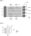
- FIG. 1 is a schematic cross-sectional view exemplifying the electrode member in the present disclosure
- FIG. 2 is a schematic perspective view exemplifying the liquid injection frame in FIG. 1
- FIGS. 3A to 3E are schematic cross-sectional views exemplifying the temporary sealing step, the gas storing step and the degassing step and the sealing step in the present disclosure.
- FIG. 1 is a schematic cross-sectional view exemplifying the electrode member in the present disclosure.
- electrode member EM that includes electrode layered body 10 including a plurality of electrode E layered in a z axis direction, and liquid injection frame 20 made of a resin arranged in a side surface SS of the electrode layered body 10, is prepared (a preparing step).
- the liquid injection frame 20 shown in FIG. 2 includes three liquid injection ports 21a, 21b and 21c arranged in the z axis direction.
- the liquid injection ports 21a, 21b and 21c are respectively arranged to correspond to power generating units U 1 , U 2 and U 3 .
- a liquid electrolyte is injected into the electrode layered body 10 in the electrode member EM via the liquid injection frame 20 (a liquid injection step).
- a liquid injection step As shown in FIG. 1 , in side surface SS of the electrode layered body 10, penetration hole 51 leading to inside the electrode layered body 10 is formed.
- a nozzle (not illustrated) is arranged at the liquid injection port 21 in the liquid injection frame 20, and a liquid electrolyte is injected into the electrode layered body 10 via the penetration hole 51.
- the liquid injection frame 20 is temporary sealed by arranging gas pack 30 to cover an entire outer periphery of the liquid injection frame 20 when viewed from an x axis direction (a temporary sealing step).
- the liquid injection frame 20 shown in FIG. 2 includes, as surfaces configuring the outer periphery in the x axis direction, surface 22a, surface 22b, surface 22c and surface 22d.
- the gas pack 30 is welded to these surfaces. Thereby, the liquid injection frame 20 is temporary sealed with the gas pack 30.
- charging or aging is performed. A gas generated due to charging or aging is stored in space S inside the gas pack 30 (a gas storing step).
- the gas pack 30 is cut to degas (a degassing step).
- the liquid injection frame 20 is sealed with sealing member X (a part of the gas pack 30 cut by a cutting jig and remained in a state connected to the liquid injection frame 20).
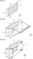
- FIGS. 4A to 4C are schematic perspective views exemplifying the temporary sealing step, the gas storing step and the degassing step in the present disclosure.
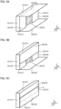
- FIGS. 5A to 5C are schematic perspective views exemplifying the sealing step in the present disclosure.
- the liquid injection frame 20 shown in FIG. 4A includes a plurality of liquid injection port 21 respectively in the y axis direction and the z axis direction, and the total number of the liquid injection port 21 is 12.
- the liquid injection frame 20 shown in FIG. 4A includes, as surfaces configuring the outer periphery in the x axis direction, surface 22a, surface 22b, surface 22c and surface 22d.
- gas pack 30 is welded to surfaces 22a to 22d. Thereby, the liquid injection frame 20 is temporary sealed with the gas pack 30 (a temporary sealing step). Then, charging or aging is performed. A gas generated due to charging or aging is stored in a space inside the gas pack 30 (a gas storing step).
- FIG. 4A includes, as surfaces configuring the outer periphery in the x axis direction, surface 22a, surface 22b, surface 22c and surface 22d.
- gas pack 30 is welded to surfaces 22a to 22d.
- the liquid injection frame 20 is temporary sealed with the gas pack 30 (a temporary sealing
- the gas pack 30 is cut in y-z plane to degas (a degassing step). Further, when viewed from the x axis direction, in four corners of the gas pack 30, notches C 1 to C 4 are made in the x axis direction.
- gas pack part 31 a part of the gas pack covering the entire outer periphery of the liquid injection frame 20 is indicated as gas pack part 31.
- the gas pack part 31 includes first surface 31a, second surface 31b, third surface 31c and fourth surface 31d.
- the first surface 31a, the second surface 31b, the third surface 31c and the fourth surface 31d respectively cover the surface 22a, the surface 22b, the surface 22c and the surface 22d in FIG. 4A .
- the first surface 31a and the second surface 31b face to each other in the z axis direction
- the third surface 31c and the fourth surface 31d face to each other in the y axis direction.
- extending part 32 extending from the gas pack part 31 is used as a sealing member.
- the extending part 32 corresponds to a part of the gas pack 30 cut by a cutting jig and remained in a state connected to the liquid injection frame 20.
- the extending part 32 includes first extending part 32a extending from the first surface 31a, second extending part 32b extending from the second surface 31b, third extending part 32c extending from the third surface 31c, and fourth extending part 32d extending from the fourth surface 31d.
- the third extending part 32c and the fourth extending part 32d are welded on open surface 23 (surface of which normal direction is the x axis direction) in the liquid injection frame 20.
- the first extending part 32a is welded to the open surface 23 in the liquid injection frame 20 interposing the third extending part 32c and the fourth extending part 32d.
- the second extending part 32b is welded to the open surface 23 in the liquid injection frame 20 interposing the first extending part 32a, the third extending part 32c and the fourth extending part 32d. Thereby, the liquid injection frame 20 is sealed.
- usage of the gas pack enables the inhibition of the degrade of sealability in a liquid injection frame.
- internal pressure of a battery increases.
- gas tends to leak from a structurally weak part. For this reason, a degassing step may be performed to prevent the internal pressure of the battery from increasing.
- an operation of sealing the battery, degassing after the internal pressure increases, sealing the battery again and degassing again after the internal pressure increases that is, an operation of repeating a sealing step and a degassing step is effective.
- repetition of the sealing step and the degassing step facilitates controlling of the internal pressure of the battery lower than the pressure resistance strength of the battery.
- the operation of repeating the sealing step and the degassing step is effective since gas generation amount tends to be much.
- the liquid injection frame configured to inject the liquid electrolyte, or the sealing member (film member) may be deformed to degrade the sealability in the liquid injection frame.
- the sealing member (film member) to the liquid injection frame when an operation of thermal welding of the sealing member (film member) to the liquid injection frame is repeated, at least one of the liquid injection frame and the sealing member is easily deformed, which may lead to the degrade of the sealability in the liquid injection frame.
- the gas pack is used to temporary seal the liquid injection frame. Since the gas pack includes an internal space, the increase of the internal pressure of a battery may be lightened compared to when, for example, temporary sealing is performed using a film member. As a result, repetition of the sealing step and the degassing step may not be necessary or the time of performing the steps may be reduced. As a result, deformation of at least one of the liquid injection frame and the sealing member does not easily occur, and the degrade of the sealability in the liquid injection frame can be inhibited.
- liquid injection frame is temporary sealed with the gas pack, and thus the gas and the liquid electrolyte can be stored in the space inside the gas pack. As a result, the spreading of the liquid electrolyte outside the battery can be inhibited. Further, as described later, a part of the gas pack cut by a cutting jig and remained in a state connected to the liquid injection frame is used as the sealing member, and thus cost reduction can be achieved.
- the preparing step in the present disclosure is a step of preparing an electrode member that includes an electrode layered body including a plurality of electrode layered in a z axis direction, and a liquid injection frame made of a resin arranged in a side surface of the electrode layered body.
- the electrode layered body in the present disclosure includes a plurality of electrode layered in a z axis direction.
- the electrode includes a current collector, and an electrode layer (cathode layer or anode layer) arranged on at least one surface of the current collector.
- the electrode layered body 10 includes a plurality of electrode E layered in a z axis direction.
- the electrode layered body 10 shown in FIG. 1 includes, as the electrode E, bipolar electrode BP 1 , bipolar electrode BP 2 , cathode side end electrode CA and anode side end electrode AN.
- the bipolar electrode BP 1 and the bipolar electrode BP 2 respectively include cathode layer 2 arranged on one surface of current collector 1, and anode layer 3 arranged on the other surface of the current collector 1.
- the cathode side end electrode CA includes the current collector 1 and the cathode layer 2 arranged on one surface of the current collector 1.
- the anode side end electrode AN includes the current collector 1 and the anode layer 3 arranged on one surface of the current collector 1.
- the electrode layered body 10 may include bipolar electrode BP including, as the electrode E, current collector 1, cathode layer 2 arranged on one surface of the current collector 1, and anode layer 3 arranged on the other surface of the current collector 1.
- the electrode layered body in the present disclosure may include just one of the bipolar electrode BP, and may include two or more thereof. Meanwhile, the electrode layered body in the present disclosure is not particularly limited if it is the one including a plurality of the electrode E layered in the z axis direction, and may not include the bipolar electrode.
- the electrode layered body 10 is provided with power generating unit U (U 1 to U 3 ).
- the power generating unit U includes cathode layer 2, anode layer 3, and separator 4 arranged between the cathode layer 2 and the anode layer 3.
- the cathode layer 2, the anode layer 3 and the separator 4 are respectively impregnated with the liquid electrolyte.
- the electrode layered body in the present disclosure may include one of the power generating unit, and may include two or more thereof.
- the electrode layered body 10 may include a plurality of the power generating unit U (U 1 , U 2 , U 3 ) layered in the z axis direction.
- the plurality of the power generating unit U (U 1 , U 2 , U 3 ) may be connected to each other in series.
- the plurality of the power generating unit may be connected to each other in parallel.
- the plurality of the power generating unit is respectively independent so that the liquid electrolyte does not flow among each other.
- the plurality of the power generating unit U (U 1 , U 2 , U 3 ) is respectively independent so that the liquid electrolyte does not flow among each other.
- the power generating unit U 1 and the power generating unit U 2 are divided by the current collector 1 and the sealing member 5, and thus respectively independent.
- the electrode layered body 10 includes the bipolar electrode BP 1 and the bipolar electrode BP 2 in the z axis direction.
- the separator 4 is arranged between the bipolar electrode BP 1 and the bipolar electrode BP 2 adjacent to each other.
- the power generating unit U 2 is configured by cathode layer 2 in the bipolar electrode BP 2 , anode layer 3 in the bipolar electrode BP 1 , and the separator 4 arranged between them.
- the power generating unit U 1 is configured by cathode layer 2 in the bipolar electrode BP 1 , anode layer 3 in the anode side end electrode AN, and the separator 4 arranged between them.
- the power generating unit U 3 is configured by anode layer 3 in the bipolar electrode BP 2 , cathode layer 2 in the cathode side end electrode CA, and the separator 4 arranged between them.
- frame shaped sealing member 5 is preferably arranged along the outer periphery of the current collector 1.
- the sealing member is preferably a resin member.
- the resin configuring the resin member may include a thermoplastic resin.
- the thermoplastic resin may include olefin-based resins such as polyethylene and polypropylene.
- the sealing member 5 preferably includes penetration hole 51 for supplying the liquid electrolyte into the electrode layered body 10. As shown in FIG. 1 , the penetration hole 51 preferably extends in the x axis direction.
- the shape of the electrode layered body in a plan view may include a square shape such as a foursquare shape and a rectangular shape.
- the length of one side of the shape of the electrode layered body in a plan view is, for example, 30 cm or more, may be 50 cm or more, and may be 100 cm or more. Meanwhile, the length of the one side is, for example, 200 cm or less.
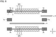
- FIG. 6 is a schematic cross-sectional view (exploded view) exemplifying the method for preparing the electrode layered body in the present disclosure.
- bipolar electrode BP 1 and bipolar electrode BP 2 are prepared.
- the bipolar electrode BP 1 includes cathode layer 2 arranged on one surface of current collector 1, and anode layer 3 arranged on the other surface of the current collector 1.
- the bipolar electrode BP 1 includes frame member 5a for forming a sealing member, arranged along the outer periphery of the current collector 1.
- the frame member 5a is usually arranged along the entire outer periphery of the current collector 1.
- the frame member 5a preferably covers a part of one main surface p of the current collector 1, a part of the other main surface q of the current collector 1, and a whole of side surface r configuring the outer periphery of the current collector 1.
- the bipolar electrode BP 2 includes cathode layer 2 arranged on one surface of the current collector 1, and anode layer 3 arranged on the other surface of the current collector 1. Further, the bipolar electrode BP 2 includes frame member 5b for forming a sealing member, arranged along the outer periphery of the current collector 1. Details of the bipolar electrode BP 2 are the same as the details of the bipolar electrode BP 1 described above.
- the anode layer 3 in the bipolar electrode BP 1 and the cathode layer 2 in the bipolar electrode BP 2 are faced to each other interposing separator 4.
- at least a part of the outer periphery of the separator 4 is arranged between the frame member 5a and the frame member 5b.
- nest 6 and frame member (spacer) 5c are arranged between the frame member 5a in the bipolar electrode BP 1 and the frame member 5b in the bipolar electrode BP 2 .
- cathode side end electrode CA and anode side end electrode AN are layered on the bipolar electrode BP 1 and the bipolar electrode BP 2 respectively interposing the separator 4. After that, a plurality of the frame members layered are welded to form a sealing member. In this manner, the electrode layered body in which a nest is inserted is obtained.
- the liquid injection frame in the present disclosure is arranged in a side surface of the electrode layered body.
- the side surface of the electrode layered body refers to a surface extending in the z axis direction in the electrode layered body.
- the side surface of the electrode layered body is usually a surface connecting a top surface (one main surface) of the electrode layered body and a bottom surface (the other main surface) of the electrode layered body facing to each other in the z axis direction.
- the liquid injection frame is made of a resin.
- the resin configuring the liquid injection frame may include a thermoplastic resin.
- the thermoplastic resin may include olefin-based resins such as polyethylene and polypropylene.
- the liquid injection frame 20 includes liquid injection port 21.
- the liquid injection port 21 is a member capable of supplying the liquid electrolyte in the x axis direction orthogonal to the z axis direction.
- the liquid injection frame 20 may include a plurality of the liquid injection port 21 (21a, 21b, 21c) arranged in the z axis direction.
- the liquid injection frame may include just one of the liquid injection port.
- the liquid injection frame 20 may include a plurality of the liquid injection port 21 arranged in a y axis direction.
- the liquid injection frame 20 in FIG. 4A may include a plurality of the liquid injection port 21 arranged in the z axis direction.
- the liquid injection frame 20 may include, as surfaces configuring the outer periphery, surface 22a, surface 22b, surface 22c and surface 22d. The later described gas pack is welded to these surfaces.
- the surface 22a and the surface 22b are arranged so as to face to each other.
- the surface 22c and the surface 22d are arranged so as to face to each other.
- the electrode member in the present disclosure includes an electrode layered body including a plurality of electrode layered in a z axis direction, and a liquid injection frame made of a resin arranged in a side surface of the electrode layered body.
- FIGS. 7A and 7B are schematic cross-sectional views exemplifying the method for preparing the electrode member in the present disclosure.
- FIG. 7A first, electrode layered body 10 in which nest 6 is inserted is prepared. In the electrode layered body 10, one end t1 of the nest 6 is positioned inside the electrode layered body 10, and the other end t2 of the nest 6 is positioned outside the electrode layered body 10.
- liquid injection frame 20 made of a resin is arranged in side surface SS of the electrode layered body 10.
- the liquid injection port 21 in the liquid injection frame 20 is arranged so as not to interfere with the end t2 of the nest 6.
- the liquid injection frame 20 may be fixed in the side surface SS of the electrode layered body 10 by welding the liquid injection frame 20 in the side surface SS of the electrode layered body 10.
- the liquid injection frame 20 may be arranged in the side surface SS of the electrode layered body 10 by a resin molding such as an injection molding.
- the liquid injection step in the present disclosure is a step of injecting a liquid electrolyte into the electrode layered body in the electrode member via the liquid injection frame.
- a liquid electrolyte is introduced to the liquid injection port (such as liquid injection port 21 in FIG. 1 ), and supplied into the electrode layered body via a penetration hole (such as penetration hole 51 in FIG. 1 ).
- the temporary sealing step in the present disclosure is a step of temporary sealing the liquid injection frame by arranging a gas pack to cover an entire outer periphery of the liquid injection frame when viewed from an x axis direction orthogonal to the z axis direction, after the liquid injection step.
- the gas pack preferably includes a film member.
- the film member preferably includes a metal layer.
- the film member including the metal layer improves gas barrier properties.
- the film member when a part of the gas pack is used as the sealing member, the film member preferably includes the metal layer.
- the materials of the metal layer may include aluminum, an aluminum alloy, and stainless steel.
- the thickness of the metal layer is, for example, 30 um or more and 60 um or less.
- the film member may not include the metal layer since high gas barrier properties are not required.
- the film member preferably includes a resin layer.
- the film member including the resin layer improves the adhesion with the liquid injection frame made of a resin.
- the resin layer in the gas pack and the liquid injection frame are preferably welded.
- the materials of the resin layer may include a thermoplastic resin.
- the thermoplastic resin may include olefin-based resins such as polyethylene and polypropylene; and ester-based resins such as polyethylene terephthalate.
- the film member may include just one layer or two layers or more of the resin layer, and may include the resin layer and the metal layer.
- the film member preferably includes layers in the order of a first resin layer, a metal layer, and a second resin layer in a thickness direction.
- the first resin layer preferably contains an olefin-based resin such as polyethylene and polypropylene.
- the thickness of the first resin layer is, for example, 40 um or more and 100 um or less.
- the material and the thickness of the metal layer are as described above.
- the second resin layer preferably contains an ester-based resin such as polyethylene terephthalate. The thickness of the second resin layer is, for example, 40 um or more and 100 um or less.
- the gas pack is preferably configured by the film member.
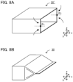
- hollow member 30' of which outer periphery of the cross-section in the x-axis direction is square, is formed.
- two central points in the z axis direction are respectively indicated as P 1 and P 2 .
- the central point P 1 and the central point P 2 are respectively pushed into the center side of the end surface, and heating and pressing are performed in that state from the z axis direction.
- gas pack 30 shown in FIG. 8B is obtained.
- the gas pack 30 includes internal space S capable of storing gas generated due to charging or aging.
- the internal space S is included, and thus increase in the internal pressure of the battery due to the gas is inhibited.
- the maximum volume of the internal space S and to one liquid injection port, for example, it is 200 cm 3 or more and 1000 cm 3 or less, and may be 500 cm 3 or more and 900 cm 3 or less.
- the volume (apparent volume) of the internal space of the gas pack when the liquid injection frame is temporary sealed may be smaller than the maximum volume of the internal space.
- the volume (apparent volume) of the internal space of the gas pack of which liquid injection frame is temporary sealed is smaller than the maximum volume of the internal space.
- the volume (apparent volume) of the internal space is increased by the gas generated due to charging or aging.
- gas pack 30 is arranged to cover an entire outer periphery of the liquid injection frame 20.
- the liquid injection frame 20 includes, as surfaces configuring the outer periphery in the x axis direction, surface 22a, surface 22b, surface 22c and surface 22d. To these surfaces, the gas pack 30 is arranged and the liquid injection frame 20 is temporary sealed.
- the surface 22a and the surface 22b are faced to each other in the z axis direction, and the surface 22c and the surface 22d are faced to each other in the y axis direction.
- the gas pack in the present disclosure usually does not correspond to an outer package covering the electrode member overall.
- the reason therefor is because the liquid electrolyte permeated into the electrode layered body is basically sealed with the sealing member (such as sealing member 5 in FIG. 1 ) and the current collector (such as current collector 1 in FIG. 1 ).
- the sealing member such as sealing member 5 in FIG. 1
- the current collector such as current collector 1 in FIG. 1
- the sealing member such as sealing member 5 in FIG. 1
- the current collector such as current collector 1 in FIG. 1
- the gas storing step in the present disclosure is a step of storing a gas generated due to charging or aging in a space inside the gas pack after the temporary sealing step.
- gas is generated by, for example, decomposition of the liquid electrolyte, and the internal pressure of the electrode member (battery) increases.
- the gas is voluntary spread to the liquid injection port (such as liquid injection port 21 in FIG. 1 ) side via the penetration hole (such as penetration hole 51 in FIG. 1 ), and stored in the space inside the gas pack.
- the battery may be charged until the SOC (State of Charge) becomes 50% or more, may be charged until the SOC becomes 70% or more, and may be charged until the SOC becomes 90% or more.
- the aging temperature is, for example, 35°C or more and 85°C or less, and maybe 40°C or more and 80°C or less.
- the aging time is, for example, 10 hours or more and 20 hours or more.
- the degassing step in the present disclosure is a step of degassing the gas by opening the gas pack after the gas storing step.
- Examples of the method for opening the gas pack may include a method of cutting the gas pack and a method of making a hole in the gas pack.
- the gas stored in the space inside the gas pack 30 may be degassed by cutting the gas pack 30.
- the gas stored in the space inside the gas pack may be degassed by making a hole in the gas pack, and then, the gas pack may be appropriately cut in accordance with the treatment performed in the later described sealing step.
- the sealing step in the present disclosure is a step of sealing the liquid injection frame with a sealing member after the degassing step.
- the sealing step is preferably performed in a reduced pressure atmosphere.
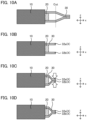
- the sealing member preferably includes at least one of: (i) a part of the gas pack cut by a cutting jig and remained in a state connected to the liquid injection frame, (ii) a part of the gas pack cut by a cutting jig and cut out from the liquid injection frame, and (iii) a member other than the gas pack.
- the liquid injection frame is sealed with a sealing member including a part of the gas pack cut by a cutting jig and remained in a state connected to the liquid injection frame.
- a sealing member including a part of the gas pack cut by a cutting jig and remained in a state connected to the liquid injection frame.
- FIG. 3A when the gas pack 30 is cut by a cutting jig (not illustrated), as shown in FIG. 3B , a part of the gas pack 30 remains in a state connected to the liquid injection frame 20.
- the liquid injection frame 20 is sealed by, for example, as shown in FIGS. 3C to 3D , using the remained gas pack 30 as sealing member X.
- FIG. 3A when the gas pack 30 is cut by a cutting jig (not illustrated), as shown in FIG. 3B , a part of the gas pack 30 remains in a state connected to the liquid injection frame 20.
- the liquid injection frame 20 is sealed by, for example, as shown in FIGS. 3C to 3D
- the first extending part 32a is thermally welded on open surface ⁇ of the liquid injection frame 20 using a heat bar, for example.
- the second extending part 32b is thermally welded on the first extending part 32a using a heat bar, for example.
- a residue of the liquid electrolyte may be present between the first extending part 32a and the second extending part 32b.
- the extending part 32 extending from the gas pack part 31 is used as a sealing member.
- the extending part 32 includes first extending part 32a extending from the first surface 31a, second extending part 32b extending from the second surface 31b, third extending part 32c extending from the third surface 31c, and fourth extending part 32d extending from the fourth surface 31d.
- a layered part ⁇ in which at least two or more of the first extending part 32a, the second extending part 32b, the third extending part 32c and the fourth extending part 32d are layered in the x axis direction, is formed.
- the liquid injection frame may be sealed without forming the above described layered part.
- the gas pack 30 is cut by a cutting jig (not illustrated) to form just first extending part 32a as the extending part 32.
- the first extending part 32a is welded on open surface ⁇ of the liquid injection frame 20.
- the liquid injection frame 20 is sealed without forming the above described layered part.
- the above described third extending part and fourth extending part may also be cut by the cutting jig.
- the liquid injection frame may be sealed without welding the extending part onto the open surface of the liquid injection frame.
- the gas pack 30 is cut by a cutting jig (not illustrated) to form first extending part 32a and second extending part 32b.
- the first extending part 32a and the second extending part 32b are welded so as to face to each other in the z axis direction.
- the liquid injection frame 20 is sealed without welding the extending part 32 onto the open surface ⁇ of the liquid injection frame 20.
- the third extending part and the fourth extending part are preferably pushed into the center side of the end surface.
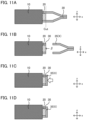
- the liquid injection frame is sealed with a sealing member including a part of the gas pack cut by a cutting jig and cut out from the liquid injection frame.
- a sealing member including a part of the gas pack cut by a cutting jig and cut out from the liquid injection frame.
- FIG. 11A when the gas pack 30 is cut by a cutting jig (not illustrated), as shown in FIG. 11B , a part of the gas pack 30 is cut out from the liquid injection frame 20.
- the liquid injection frame 20 is sealed by, for example, as shown in FIGS. 11C and 11D , using the cut-out gas pack 35 as a sealing member X.
- the gas pack 35 is welded onto the open surface ⁇ of the liquid injection frame 20.
- FIG. 11D the liquid injection frame 20 is sealed with the gas pack 35.
- the (ii) and the (i) may be combined.
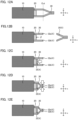
- a cutting jig (not illustrated)
- FIG. 12B a part of the gas pack 30 remains in a state connected to the liquid injection frame 20.
- the remaining gas pack 30 is used as the sealing member X.
- the cutting a part of the gas pack 30 is cut out from the liquid injection frame 20.
- the cut-out gas pack 35 is also used as the sealing member X.
- the gas pack 35 is welded onto the open surface ⁇ of the liquid injection frame 20.
- the first extending part 32a and the second extending part 32b are welded so as to face to each other in the z axis direction. Thereby, as shown in FIG. 12E , the liquid injection frame 20 is sealed with the sealing member X.
- the liquid injection frame is sealed by using a member other than the gas pack as the sealing member X.
- the member other than the gas pack may include a film member. Details of the film member are in the same contents as those of the film member configuring the gas pack described above; thus the descriptions herein are omitted.
- the member other than the gas pack such as a film member
- the gas pack 35 described in FIGS. 11A to 11D and FIGS. 12A to 12E .
- the (iii) and the (i) may be combined.
- the (i), the (ii) and the (iii) may be combined.
- the battery in the present disclosure is preferably a secondary battery (such as a lithium ion secondary battery).
- Examples of the applications of the battery may include a power source for vehicles such as hybrid electric vehicles (HEV), plug-in hybrid electric vehicles (PHEV), battery electric vehicles (BEV), gasolinefueled automobiles and diesel powered automobiles.
- a power source for vehicles such as hybrid electric vehicles (HEV), plug-in hybrid electric vehicles (PHEV), and battery electric vehicles (BEV).
- HEV hybrid electric vehicles
- PHEV plug-in hybrid electric vehicles
- BEV battery electric vehicles
- the battery in the present disclosure may be used as a power source for moving bodies other than vehicles (such as rail road transportation, vessel and airplane), and may be used as a power source for electronic products such as information processing equipment.
- FIG. 13 is a schematic cross-sectional view exemplifying the battery in the present disclosure.
- Battery 100 illustrated in FIG. 13 includes electrode layered body 10 including a plurality of electrode E layered in the z axis direction, liquid injection frame 20 made of a resin arranged in a side surface of the electrode layered body 10, a liquid electrolyte (not illustrated) permeated to the electrode layered body 10, and sealing member X that seals the liquid injection frame 20.
- gas pack part 31 when viewed from the x axis direction, gas pack part 31 is arranged to cover an entire outer periphery of the liquid injection frame 20, and the gas pack part 31 includes first surface 31a and second surface 31b facing to each other.
- FIG. 5C when viewed from the x axis direction, gas pack part 31 is arranged to cover an entire outer periphery of the liquid injection frame 20, and the gas pack part 31 includes first surface 31a and second surface 31b facing to each other.
- the sealing member includes first extending part 32a extending from the first surface 31a, and second extending part 32b extending from the second surface 31b. Also, when viewed from the x axis direction, layered part ⁇ , in which the first extending part 32a and the second extending part 32b are layered, is arranged.
- the specified layered part ⁇ is arranged, and thus the degrade in sealability due to deformation of the liquid injection frame is inhibited in the battery.
- the details of the battery in the present disclosure are in the same contents as those described in "A. Method for producing battery" above.
- the sealing member may include third extending part 32c and fourth extending part 32d.
- the present disclosure is not limited to the embodiments.
- the embodiments are exemplification, and any other variations are intended to be included in the technical scope of the present disclosure if they have substantially the same constitution as the technical idea described in the claims of the present disclosure and have similar operation and effect thereto.
Landscapes
- Chemical & Material Sciences (AREA)
- Chemical Kinetics & Catalysis (AREA)
- Electrochemistry (AREA)
- General Chemical & Material Sciences (AREA)
- Engineering & Computer Science (AREA)
- Manufacturing & Machinery (AREA)
- General Physics & Mathematics (AREA)
- Physics & Mathematics (AREA)
- Condensed Matter Physics & Semiconductors (AREA)
- Inorganic Chemistry (AREA)
- Materials Engineering (AREA)
- Secondary Cells (AREA)
- Sealing Battery Cases Or Jackets (AREA)
- Filling, Topping-Up Batteries (AREA)
- Gas Exhaust Devices For Batteries (AREA)
Abstract
Description
- The present disclosure relates to a method for producing a battery and a battery.
- In a method for producing a battery such as a lithium ion secondary battery, it has been known that a degassing step is performed to prevent the internal pressure of a battery from increasing due to gas generated in a charging step or an aging step.
Patent Literature 1 discloses a method for producing a secondary battery wherein a charging step, a degassing step and an aging step are performed in a state a pair of wide width surfaces of a battery case are sandwiched from both sides and pressed in the direction of the sandwiching. Also, for example,Patent Literature 2 discloses that a pressure adjusting unit is arranged in a side surface of a battery to prevent the internal pressure of the battery from increasing. -
- Patent Literature 1: Japanese Patent Application Laid-Open (
JP-A) No. 2010-021104 - Patent Literature 2:
JP-A No. 2019-016459 - As described above, when gas is generated in a charging step or an aging step, internal pressure of a battery increases. When the internal pressure of a battery increases, gas tends to leak from a structurally weak part. For this reason, a degassing step may be performed to prevent the internal pressure of the battery from increasing.
- In order to suppress the internal pressure of a battery, for example, an operation of sealing the battery, degassing after the internal pressure increases, sealing the battery again and degassing again after the internal pressure increases, that is, an operation of repeating a sealing step and a degassing step is effective. Meanwhile, when the sealing step and the degassing step are repeated, a liquid injection frame configured to inject a liquid electrolyte, or a sealing member may be deformed to degrade sealability of the liquid injection frame.
- The present disclosure has been made in view of the above circumstances, and a main object of thereof is to provide a method for producing a battery in which the degrade of sealability in a liquid injection frame is inhibited.
-
- [1] A method for producing a battery, the method comprising:
- a preparing step of preparing an electrode member that includes an electrode layered body including a plurality of electrode layered in a z axis direction, and a liquid injection frame made of a resin arranged in a side surface of the electrode layered body;
- a liquid injection step of injecting a liquid electrolyte into the electrode layered body in the electrode member via the liquid injection frame;
- a temporary sealing step of temporary sealing the liquid injection frame by arranging a gas pack to cover an entire outer periphery of the liquid injection frame when viewed from an x axis direction orthogonal to the z axis direction, after the liquid injection step;
- a gas storing step of storing a gas generated due to charging or aging in a space inside the gas pack after the temporary sealing step;
- a degassing step of degassing the gas by opening the gas pack after the gas storing step; and
- a sealing step of sealing the liquid injection frame with a sealing member after the degassing step.
- [2] The method for producing a battery according to [1], wherein the sealing member includes at least one of: (i) a part of the gas pack cut by a cutting jig and remained in a state connected to the liquid injection frame, (ii) a part of the gas pack cut by a cutting jig and cut out from the liquid injection frame, and (iii) a member other than the gas pack.
- [3] The method for producing a battery according to [2], wherein the sealing member includes the (i).
- [4] The method for producing a battery according to [2], wherein the sealing member includes the (ii).
- [5] The method for producing a battery according to [2], wherein the sealing member includes the (iii).
- [6] The method for producing a battery according to [3] or [4], wherein
- the gas pack includes a film member; and
- in the sealing step, a layered part, in which a plurality of the film member is layered in the x axis direction, is formed.
- [7] The method for producing a battery according to any one of [1] to [6], wherein
- the gas pack includes a film member; and
- the film member includes layers in the order of a first resin layer, a metal layer, and a second resin layer in a thickness direction.
- [8] The method for producing a battery according to any one of [1] to [7], wherein
- the liquid injection frame includes a resin; and
- the gas pack is welded to cover an entire outer periphery of the liquid injection frame in the temporary sealing step.
- [9] The method for producing a battery according to any one of [1] to [8], wherein
- the liquid injection frame includes a resin; and
- the sealing member is welded in an open surface of the liquid injection frame.
- [10] The method for producing a battery according to any one of [1] to [9], wherein
- a shape of the electrode layered body in a plan view is a square; and
- a length of one side of the square is 30 cm or more.
- [11] The method for producing a battery according to any one of [1] to [10], wherein the liquid injection frame includes a plurality of a liquid injection port in the z axis direction.
- [12] The method for producing a battery according to any one of [1] to [11], wherein the liquid injection frame includes a plurality of a liquid injection port in a y axis direction orthogonal to the z axis direction and the x axis direction.
- [13] A battery comprising:
- an electrode layered body including a plurality of electrode layered in a z axis direction;
- a liquid injection frame made of a resin arranged in a side surface of the electrode layered body;
- a liquid electrolyte permeated to the electrode layered body; and
- a sealing member that seals the liquid injection frame; wherein
- when viewed from an x axis direction orthogonal to the z axis direction, a gas pack part is arranged to cover an entire outer periphery of the liquid injection frame;
- the gas pack part includes a first surface and a second surface facing to each other;
- the sealing member includes a first extending part extending from the first surface, and a second extending part extending from the second surface; and
- when viewed from the x axis direction, a layered part, in which the first extending part and the second extending part are layered, is arranged.
- [14] The battery according to [13], wherein a residue of the liquid electrolyte is present between the first extending part and the second extending part in the layered part.
- The method for producing a battery in the present disclosure exhibits an effect of inhibiting the degrade of sealability in a liquid injection frame.
-
-
FIG. 1 is a schematic cross-sectional view exemplifying the electrode member in the present disclosure. -
FIG. 2 is a schematic perspective view exemplifying the liquid injection frameFIG. 1 . -
FIGS. 3A to 3E are schematic cross-sectional views exemplifying the temporary sealing step, the gas storing step, the degassing step and the sealing step in the present disclosure. -
FIGS. 4A to 4C are schematic perspective views exemplifying the temporary sealing step, the gas storing step and the degassing step in the present disclosure. -
FIGS. 5A to 5C are schematic perspective views exemplifying the sealing step in the present disclosure. -
FIG. 6 is a schematic cross-sectional view (exploded view) exemplifying the method for preparing the electrode layered body in the present disclosure. -
FIGS. 7A and 7B are schematic cross-sectional views exemplifying the method for preparing the electrode layered body in the present disclosure. -
FIGS. 8A and 8B are schematic cross-sectional views exemplifying the method for preparing the gas pack in the present disclosure. -
FIGS. 9A to 9D are schematic cross-sectional views exemplifying the degassing step and the sealing step in the present disclosure. -
FIGS. 10A to 10D are schematic cross-sectional views exemplifying the degassing step and the sealing step in the present disclosure. -
FIGS. 11A to 11D are schematic cross-sectional views exemplifying the degassing step and the sealing step in the present disclosure. -
FIGS. 12A to 12E are schematic cross-sectional views exemplifying the degassing step and the sealing step in the present disclosure. -
FIG. 13 is a schematic cross-sectional view exemplifying the battery in the present disclosure. - The embodiments in the present disclosure will be hereinafter explained in details with reference to drawings. Each drawing described as below is a schematic view, and the size and the shape of each portion are appropriately exaggerated in order to be understood easily. Furthermore, in the present description, upon expressing an embodiment of arranging one member with respect to the other member, when it is expressed simply "on" or "below", both of when the other member is directly arranged on or below the one member so as to contact with each other, and when the other member is arranged above or below the one member interposing an additional member, can be included unless otherwise described.
- An example of the method for producing a battery in the present disclosure will be explained with reference to
FIG. 1 to FIG. 3E .FIG. 1 is a schematic cross-sectional view exemplifying the electrode member in the present disclosure,FIG. 2 is a schematic perspective view exemplifying the liquid injection frame inFIG. 1 , andFIGS. 3A to 3E are schematic cross-sectional views exemplifying the temporary sealing step, the gas storing step and the degassing step and the sealing step in the present disclosure. -
FIG. 1 is a schematic cross-sectional view exemplifying the electrode member in the present disclosure. As shown inFIG. 1 , electrode member EM that includes electrode layeredbody 10 including a plurality of electrode E layered in a z axis direction, andliquid injection frame 20 made of a resin arranged in a side surface SS of the electrode layeredbody 10, is prepared (a preparing step). Also, theliquid injection frame 20 shown inFIG. 2 includes threeliquid injection ports FIG. 1 , theliquid injection ports - Next, a liquid electrolyte is injected into the electrode layered
body 10 in the electrode member EM via the liquid injection frame 20 (a liquid injection step). As shown inFIG. 1 , in side surface SS of the electrode layeredbody 10,penetration hole 51 leading to inside the electrode layeredbody 10 is formed. A nozzle (not illustrated) is arranged at theliquid injection port 21 in theliquid injection frame 20, and a liquid electrolyte is injected into the electrode layeredbody 10 via thepenetration hole 51. - Next, as shown in
FIG. 3A , theliquid injection frame 20 is temporary sealed by arranginggas pack 30 to cover an entire outer periphery of theliquid injection frame 20 when viewed from an x axis direction (a temporary sealing step). For example, theliquid injection frame 20 shown inFIG. 2 includes, as surfaces configuring the outer periphery in the x axis direction,surface 22a,surface 22b,surface 22c andsurface 22d. Thegas pack 30 is welded to these surfaces. Thereby, theliquid injection frame 20 is temporary sealed with thegas pack 30. Then, charging or aging is performed. A gas generated due to charging or aging is stored in space S inside the gas pack 30 (a gas storing step). Next, as shown inFIG. 3B , thegas pack 30 is cut to degas (a degassing step). Next, as shown inFIGS. 3C to 3E , theliquid injection frame 20 is sealed with sealing member X (a part of thegas pack 30 cut by a cutting jig and remained in a state connected to the liquid injection frame 20). - Another example of the method for producing a battery in the present disclosure will be explained with reference to
FIG. 4A to FIG. 5C .FIGS. 4A to 4C are schematic perspective views exemplifying the temporary sealing step, the gas storing step and the degassing step in the present disclosure.FIGS. 5A to 5C are schematic perspective views exemplifying the sealing step in the present disclosure. - The
liquid injection frame 20 shown inFIG. 4A includes a plurality ofliquid injection port 21 respectively in the y axis direction and the z axis direction, and the total number of theliquid injection port 21 is 12. Theliquid injection frame 20 shown inFIG. 4A includes, as surfaces configuring the outer periphery in the x axis direction,surface 22a,surface 22b,surface 22c andsurface 22d. Next, as shown inFIG. 4B ,gas pack 30 is welded tosurfaces 22a to 22d. Thereby, theliquid injection frame 20 is temporary sealed with the gas pack 30 (a temporary sealing step). Then, charging or aging is performed. A gas generated due to charging or aging is stored in a space inside the gas pack 30 (a gas storing step). Next, as shown inFIG. 4C , thegas pack 30 is cut in y-z plane to degas (a degassing step). Further, when viewed from the x axis direction, in four corners of thegas pack 30, notches C1 to C4 are made in the x axis direction. - As shown in
FIG. 5A , a part of the gas pack covering the entire outer periphery of theliquid injection frame 20 is indicated asgas pack part 31. Thegas pack part 31 includesfirst surface 31a,second surface 31b,third surface 31c andfourth surface 31d. Thefirst surface 31a, thesecond surface 31b, thethird surface 31c and thefourth surface 31d respectively cover thesurface 22a, thesurface 22b, thesurface 22c and thesurface 22d inFIG. 4A . Also, thefirst surface 31a and thesecond surface 31b face to each other in the z axis direction, and thethird surface 31c and thefourth surface 31d face to each other in the y axis direction. - In
FIG. 5A , extendingpart 32 extending from thegas pack part 31 is used as a sealing member. The extendingpart 32 corresponds to a part of thegas pack 30 cut by a cutting jig and remained in a state connected to theliquid injection frame 20. The extendingpart 32 includes first extendingpart 32a extending from thefirst surface 31a, second extendingpart 32b extending from thesecond surface 31b, third extendingpart 32c extending from thethird surface 31c, and fourth extendingpart 32d extending from thefourth surface 31d. - As shown in
FIG. 5A , the third extendingpart 32c and the fourth extendingpart 32d are welded on open surface 23 (surface of which normal direction is the x axis direction) in theliquid injection frame 20. Next, as shown inFIG. 5B , the first extendingpart 32a is welded to theopen surface 23 in theliquid injection frame 20 interposing the third extendingpart 32c and the fourth extendingpart 32d. Next, as shown inFIG. 5C , the second extendingpart 32b is welded to theopen surface 23 in theliquid injection frame 20 interposing the first extendingpart 32a, the third extendingpart 32c and the fourth extendingpart 32d. Thereby, theliquid injection frame 20 is sealed. - According to the present disclosure, usage of the gas pack enables the inhibition of the degrade of sealability in a liquid injection frame. As described above, when gas is generated in a charging step or an aging step, internal pressure of a battery increases. When the internal pressure of a battery increases, gas tends to leak from a structurally weak part. For this reason, a degassing step may be performed to prevent the internal pressure of the battery from increasing.
- In order to suppress the internal pressure of a battery, for example, an operation of sealing the battery, degassing after the internal pressure increases, sealing the battery again and degassing again after the internal pressure increases, that is, an operation of repeating a sealing step and a degassing step is effective. In specific, repetition of the sealing step and the degassing step facilitates controlling of the internal pressure of the battery lower than the pressure resistance strength of the battery. Particularly when a battery is in largescaled, the operation of repeating the sealing step and the degassing step is effective since gas generation amount tends to be much. On the other hand, when the sealing step and the degassing step are repeated, the liquid injection frame configured to inject the liquid electrolyte, or the sealing member (film member) may be deformed to degrade the sealability in the liquid injection frame. In specific, when an operation of thermal welding of the sealing member (film member) to the liquid injection frame is repeated, at least one of the liquid injection frame and the sealing member is easily deformed, which may lead to the degrade of the sealability in the liquid injection frame.
- In contrast, in the present disclosure, the gas pack is used to temporary seal the liquid injection frame. Since the gas pack includes an internal space, the increase of the internal pressure of a battery may be lightened compared to when, for example, temporary sealing is performed using a film member. As a result, repetition of the sealing step and the degassing step may not be necessary or the time of performing the steps may be reduced. As a result, deformation of at least one of the liquid injection frame and the sealing member does not easily occur, and the degrade of the sealability in the liquid injection frame can be inhibited. Also, along with the increase in the internal pressure of the battery, gas is emitted with a great force from a penetration hole configured to supply the liquid electrolyte, and the liquid electrolyte is also emitted from the penetration hole along with the flow of the gas, which may lead to spreading of the liquid electrolyte outside the battery. In contrast, in the present disclosure, the liquid injection frame is temporary sealed with the gas pack, and thus the gas and the liquid electrolyte can be stored in the space inside the gas pack. As a result, the spreading of the liquid electrolyte outside the battery can be inhibited. Further, as described later, a part of the gas pack cut by a cutting jig and remained in a state connected to the liquid injection frame is used as the sealing member, and thus cost reduction can be achieved.
- The preparing step in the present disclosure is a step of preparing an electrode member that includes an electrode layered body including a plurality of electrode layered in a z axis direction, and a liquid injection frame made of a resin arranged in a side surface of the electrode layered body.
- The electrode layered body in the present disclosure includes a plurality of electrode layered in a z axis direction. The electrode includes a current collector, and an electrode layer (cathode layer or anode layer) arranged on at least one surface of the current collector.
- As shown in
FIG. 1 , the electrode layeredbody 10 includes a plurality of electrode E layered in a z axis direction. The electrode layeredbody 10 shown inFIG. 1 includes, as the electrode E, bipolar electrode BP1, bipolar electrode BP2, cathode side end electrode CA and anode side end electrode AN. The bipolar electrode BP1 and the bipolar electrode BP2 respectively includecathode layer 2 arranged on one surface ofcurrent collector 1, andanode layer 3 arranged on the other surface of thecurrent collector 1. The cathode side end electrode CA includes thecurrent collector 1 and thecathode layer 2 arranged on one surface of thecurrent collector 1. The anode side end electrode AN includes thecurrent collector 1 and theanode layer 3 arranged on one surface of thecurrent collector 1. - As shown in
FIG. 1 , the electrode layeredbody 10 may include bipolar electrode BP including, as the electrode E,current collector 1,cathode layer 2 arranged on one surface of thecurrent collector 1, andanode layer 3 arranged on the other surface of thecurrent collector 1. The electrode layered body in the present disclosure may include just one of the bipolar electrode BP, and may include two or more thereof. Meanwhile, the electrode layered body in the present disclosure is not particularly limited if it is the one including a plurality of the electrode E layered in the z axis direction, and may not include the bipolar electrode. - As shown in
FIG. 1 , the electrode layeredbody 10 is provided with power generating unit U (U1 to U3). The power generating unit U includescathode layer 2,anode layer 3, andseparator 4 arranged between thecathode layer 2 and theanode layer 3. To thecathode layer 2, theanode layer 3 and theseparator 4, the liquid electrolyte is supplied viapenetration hole 51. As a result, thecathode layer 2, theanode layer 3 and theseparator 4 are respectively impregnated with the liquid electrolyte. Also, the electrode layered body in the present disclosure may include one of the power generating unit, and may include two or more thereof. - As shown in
FIG. 1 , the electrode layeredbody 10 may include a plurality of the power generating unit U (U1, U2, U3) layered in the z axis direction. As shown inFIG. 1 , the plurality of the power generating unit U (U1, U2, U3) may be connected to each other in series. Also, although not illustrated in particular, the plurality of the power generating unit may be connected to each other in parallel. The plurality of the power generating unit is respectively independent so that the liquid electrolyte does not flow among each other. InFIG. 1 , the plurality of the power generating unit U (U1, U2, U3) is respectively independent so that the liquid electrolyte does not flow among each other. For example, the power generating unit U1 and the power generating unit U2 are divided by thecurrent collector 1 and the sealingmember 5, and thus respectively independent. - One power generating unit may be configured by two bipolar electrodes. In
FIG. 1 , the electrode layeredbody 10 includes the bipolar electrode BP1 and the bipolar electrode BP2 in the z axis direction. Theseparator 4 is arranged between the bipolar electrode BP1 and the bipolar electrode BP2 adjacent to each other. The power generating unit U2 is configured bycathode layer 2 in the bipolar electrode BP2,anode layer 3 in the bipolar electrode BP1, and theseparator 4 arranged between them. On the other hand, the power generating unit U1 is configured bycathode layer 2 in the bipolar electrode BP1,anode layer 3 in the anode side end electrode AN, and theseparator 4 arranged between them. Also, the power generating unit U3 is configured byanode layer 3 in the bipolar electrode BP2,cathode layer 2 in the cathode side end electrode CA, and theseparator 4 arranged between them. - As shown in
FIG. 1 , when viewed from the z axis direction, frame shaped sealingmember 5 is preferably arranged along the outer periphery of thecurrent collector 1. The sealing member is preferably a resin member. Examples of the resin configuring the resin member may include a thermoplastic resin. Examples of the thermoplastic resin may include olefin-based resins such as polyethylene and polypropylene. Also, as shown inFIG. 1 , the sealingmember 5 preferably includespenetration hole 51 for supplying the liquid electrolyte into the electrode layeredbody 10. As shown inFIG. 1 , thepenetration hole 51 preferably extends in the x axis direction. - There are no particular limitations on the shape of the electrode layered body in a plan view (shape when viewed from the z axis direction), and examples thereof may include a square shape such as a foursquare shape and a rectangular shape. The length of one side of the shape of the electrode layered body in a plan view is, for example, 30 cm or more, may be 50 cm or more, and may be 100 cm or more. Meanwhile, the length of the one side is, for example, 200 cm or less.
- There are no particular limitations on the method for preparing the electrode layered body.
FIG. 6 is a schematic cross-sectional view (exploded view) exemplifying the method for preparing the electrode layered body in the present disclosure. As shown inFIG. 6 , bipolar electrode BP1 and bipolar electrode BP2 are prepared. The bipolar electrode BP1 includescathode layer 2 arranged on one surface ofcurrent collector 1, andanode layer 3 arranged on the other surface of thecurrent collector 1. - Further, the bipolar electrode BP1 includes
frame member 5a for forming a sealing member, arranged along the outer periphery of thecurrent collector 1. When viewed from the z axis direction, theframe member 5a is usually arranged along the entire outer periphery of thecurrent collector 1. For example, when the shape of the outer periphery of thecurrent collector 1 is square, theframe member 5a is arranged along the entire outer periphery of that square. Also, as shown inFIG. 6 , theframe member 5a preferably covers a part of one main surface p of thecurrent collector 1, a part of the other main surface q of thecurrent collector 1, and a whole of side surface r configuring the outer periphery of thecurrent collector 1. - As shown in
FIG. 6 , the bipolar electrode BP2 includescathode layer 2 arranged on one surface of thecurrent collector 1, andanode layer 3 arranged on the other surface of thecurrent collector 1. Further, the bipolar electrode BP2 includesframe member 5b for forming a sealing member, arranged along the outer periphery of thecurrent collector 1. Details of the bipolar electrode BP2 are the same as the details of the bipolar electrode BP1 described above. - As shown in
FIG. 6 , theanode layer 3 in the bipolar electrode BP1 and thecathode layer 2 in the bipolar electrode BP2 are faced to each other interposingseparator 4. On this occasion, at least a part of the outer periphery of theseparator 4 is arranged between theframe member 5a and theframe member 5b. Also, as shown inFIG. 6 ,nest 6 and frame member (spacer) 5c are arranged between theframe member 5a in the bipolar electrode BP1 and theframe member 5b in the bipolar electrode BP2. Next, although not illustrated in particular, similarly toFIG. 1 , cathode side end electrode CA and anode side end electrode AN are layered on the bipolar electrode BP1 and the bipolar electrode BP2 respectively interposing theseparator 4. After that, a plurality of the frame members layered are welded to form a sealing member. In this manner, the electrode layered body in which a nest is inserted is obtained. - The liquid injection frame in the present disclosure is arranged in a side surface of the electrode layered body. The side surface of the electrode layered body refers to a surface extending in the z axis direction in the electrode layered body. Also, the side surface of the electrode layered body is usually a surface connecting a top surface (one main surface) of the electrode layered body and a bottom surface (the other main surface) of the electrode layered body facing to each other in the z axis direction.
- The liquid injection frame is made of a resin. Examples of the resin configuring the liquid injection frame may include a thermoplastic resin. Examples of the thermoplastic resin may include olefin-based resins such as polyethylene and polypropylene.
- Also, as shown in
FIG. 2 , theliquid injection frame 20 includesliquid injection port 21. Theliquid injection port 21 is a member capable of supplying the liquid electrolyte in the x axis direction orthogonal to the z axis direction. Also, as shown inFIG. 2 , theliquid injection frame 20 may include a plurality of the liquid injection port 21 (21a, 21b, 21c) arranged in the z axis direction. On the other hand, although not illustrated in particular, the liquid injection frame may include just one of the liquid injection port. Also, as shown inFIG. 4A , theliquid injection frame 20 may include a plurality of theliquid injection port 21 arranged in a y axis direction. Similarly, theliquid injection frame 20 inFIG. 4A may include a plurality of theliquid injection port 21 arranged in the z axis direction. - There are no particular limitations on the shape of the outer periphery of the liquid injection port when viewed from the x axis direction, and examples thereof may include a square shape such as a rectangular shape and a foursquare shape. Also, there are no particular limitations on the shape of the outer periphery of the liquid injection frame when viewed from the x axis direction, and examples thereof may include a square shape such as a rectangular shape and a foursquare shape. Also, as shown in
FIG. 2 , when viewed from the x axis direction, theliquid injection frame 20 may include, as surfaces configuring the outer periphery,surface 22a,surface 22b,surface 22c andsurface 22d. The later described gas pack is welded to these surfaces. InFIG. 2 , thesurface 22a and thesurface 22b are arranged so as to face to each other. Similarly, inFIG. 2 , thesurface 22c and thesurface 22d are arranged so as to face to each other. - The electrode member in the present disclosure includes an electrode layered body including a plurality of electrode layered in a z axis direction, and a liquid injection frame made of a resin arranged in a side surface of the electrode layered body. There are no particular limitations on the method for preparing the electrode member.
FIGS. 7A and 7B are schematic cross-sectional views exemplifying the method for preparing the electrode member in the present disclosure. As shown inFIG. 7A , first, electrode layeredbody 10 in which nest 6 is inserted is prepared. In the electrode layeredbody 10, one end t1 of thenest 6 is positioned inside the electrode layeredbody 10, and the other end t2 of thenest 6 is positioned outside the electrode layeredbody 10. - Next, as shown in
FIG. 7B ,liquid injection frame 20 made of a resin is arranged in side surface SS of the electrode layeredbody 10. Theliquid injection port 21 in theliquid injection frame 20 is arranged so as not to interfere with the end t2 of thenest 6. For example, theliquid injection frame 20 may be fixed in the side surface SS of the electrode layeredbody 10 by welding theliquid injection frame 20 in the side surface SS of the electrode layeredbody 10. Also, theliquid injection frame 20 may be arranged in the side surface SS of the electrode layeredbody 10 by a resin molding such as an injection molding. - The liquid injection step in the present disclosure is a step of injecting a liquid electrolyte into the electrode layered body in the electrode member via the liquid injection frame. There are no particular limitations on the method for injecting the liquid electrolyte, and examples thereof may include a conventionally known method using an injection device. The liquid electrolyte is introduced to the liquid injection port (such as
liquid injection port 21 inFIG. 1 ), and supplied into the electrode layered body via a penetration hole (such aspenetration hole 51 inFIG. 1 ). - The temporary sealing step in the present disclosure is a step of temporary sealing the liquid injection frame by arranging a gas pack to cover an entire outer periphery of the liquid injection frame when viewed from an x axis direction orthogonal to the z axis direction, after the liquid injection step.
- The gas pack preferably includes a film member. Also, the film member preferably includes a metal layer. The film member including the metal layer improves gas barrier properties. As described later, when a part of the gas pack is used as the sealing member, the film member preferably includes the metal layer. Examples of the materials of the metal layer may include aluminum, an aluminum alloy, and stainless steel. The thickness of the metal layer is, for example, 30 um or more and 60 um or less. On the other hand, when a part of the gas pack is not used as the sealing member, the film member may not include the metal layer since high gas barrier properties are not required.
- The film member preferably includes a resin layer. The film member including the resin layer improves the adhesion with the liquid injection frame made of a resin. On the occasion of arranging the gas pack to cover the entire outer periphery of the liquid injection frame, the resin layer in the gas pack and the liquid injection frame are preferably welded. Examples of the materials of the resin layer may include a thermoplastic resin. Examples of the thermoplastic resin may include olefin-based resins such as polyethylene and polypropylene; and ester-based resins such as polyethylene terephthalate. The film member may include just one layer or two layers or more of the resin layer, and may include the resin layer and the metal layer.
- The film member preferably includes layers in the order of a first resin layer, a metal layer, and a second resin layer in a thickness direction. By arranging the first resin layer, the adhesion to the liquid injection frame made of a resin improves, and by arranging the metal layer, gas barrier properties improve, and by arranging the second resin layer, insulation improves. The first resin layer preferably contains an olefin-based resin such as polyethylene and polypropylene. The thickness of the first resin layer is, for example, 40 um or more and 100 um or less. Also, the material and the thickness of the metal layer are as described above. Also, the second resin layer preferably contains an ester-based resin such as polyethylene terephthalate. The thickness of the second resin layer is, for example, 40 um or more and 100 um or less.
- The gas pack is preferably configured by the film member. For example, as shown in
FIG. 8A , by folding the film member, hollow member 30' of which outer periphery of the cross-section in the x-axis direction is square, is formed. Next, in one end surface of the hollow member 30' in the x axis direction, two central points in the z axis direction are respectively indicated as P1 and P2. The central point P1 and the central point P2 are respectively pushed into the center side of the end surface, and heating and pressing are performed in that state from the z axis direction. Thereby,gas pack 30 shown inFIG. 8B is obtained. - For example, as shown in
FIGS. 3A to 3E , thegas pack 30 includes internal space S capable of storing gas generated due to charging or aging. The internal space S is included, and thus increase in the internal pressure of the battery due to the gas is inhibited. There are no particular limitations on the maximum volume of the internal space S, and to one liquid injection port, for example, it is 200 cm3 or more and 1000 cm3 or less, and may be 500 cm3 or more and 900 cm3 or less. Also, the volume (apparent volume) of the internal space of the gas pack when the liquid injection frame is temporary sealed may be smaller than the maximum volume of the internal space. For example, when the gas pack of which liquid injection frame is temporary sealed is folded or deflected, the volume (apparent volume) of the internal space of the gas pack of which liquid injection frame is temporary sealed is smaller than the maximum volume of the internal space. In this case, the volume (apparent volume) of the internal space is increased by the gas generated due to charging or aging. - As shown in
FIG. 4B , when viewed from the x axis direction,gas pack 30 is arranged to cover an entire outer periphery of theliquid injection frame 20. Theliquid injection frame 20 includes, as surfaces configuring the outer periphery in the x axis direction,surface 22a,surface 22b,surface 22c andsurface 22d. To these surfaces, thegas pack 30 is arranged and theliquid injection frame 20 is temporary sealed. Thesurface 22a and thesurface 22b are faced to each other in the z axis direction, and thesurface 22c and thesurface 22d are faced to each other in the y axis direction. - The gas pack in the present disclosure usually does not correspond to an outer package covering the electrode member overall. The reason therefor is because the liquid electrolyte permeated into the electrode layered body is basically sealed with the sealing member (such as sealing
member 5 inFIG. 1 ) and the current collector (such ascurrent collector 1 inFIG. 1 ). Also, when an outer package covering the electrode member overall is used, when the scale of the electrode member becomes large, it is necessary to also enlarge the scale of the outer package. In contrast, when the liquid electrolyte permeated into the electrode layered body is sealed with the sealing member (such as sealingmember 5 inFIG. 1 ) and the current collector (such ascurrent collector 1 inFIG. 1 ), it is not necessary to use the outer package covering the electrode member overall, and thus there is an advantage that the scale of the electrode member may be easily enlarged. - The gas storing step in the present disclosure is a step of storing a gas generated due to charging or aging in a space inside the gas pack after the temporary sealing step. When charging or aging is performed to the electrode member (battery) after the temporary sealing step, gas is generated by, for example, decomposition of the liquid electrolyte, and the internal pressure of the electrode member (battery) increases. Along with the increase of the internal pressure, the gas is voluntary spread to the liquid injection port (such as
liquid injection port 21 inFIG. 1 ) side via the penetration hole (such aspenetration hole 51 inFIG. 1 ), and stored in the space inside the gas pack. - There are no particular limitations on the conditions of the charging or the aging. For the conditions of the charging, for example, the battery may be charged until the SOC (State of Charge) becomes 50% or more, may be charged until the SOC becomes 70% or more, and may be charged until the SOC becomes 90% or more. Meanwhile, the aging temperature is, for example, 35°C or more and 85°C or less, and maybe 40°C or more and 80°C or less. Also, the aging time is, for example, 10 hours or more and 20 hours or more.
- The degassing step in the present disclosure is a step of degassing the gas by opening the gas pack after the gas storing step. Examples of the method for opening the gas pack may include a method of cutting the gas pack and a method of making a hole in the gas pack.
- As shown in
FIG. 3A , the gas stored in the space inside thegas pack 30 may be degassed by cutting thegas pack 30. On the other hand, although not illustrated in particular, the gas stored in the space inside the gas pack may be degassed by making a hole in the gas pack, and then, the gas pack may be appropriately cut in accordance with the treatment performed in the later described sealing step. - The sealing step in the present disclosure is a step of sealing the liquid injection frame with a sealing member after the degassing step. The sealing step is preferably performed in a reduced pressure atmosphere.
- The sealing member preferably includes at least one of: (i) a part of the gas pack cut by a cutting jig and remained in a state connected to the liquid injection frame, (ii) a part of the gas pack cut by a cutting jig and cut out from the liquid injection frame, and (iii) a member other than the gas pack.
- First, the case of the (i) will be explained. In the case of the (i), the liquid injection frame is sealed with a sealing member including a part of the gas pack cut by a cutting jig and remained in a state connected to the liquid injection frame. For example, as shown in
FIG. 3A , when thegas pack 30 is cut by a cutting jig (not illustrated), as shown inFIG. 3B , a part of thegas pack 30 remains in a state connected to theliquid injection frame 20. Theliquid injection frame 20 is sealed by, for example, as shown inFIGS. 3C to 3D , using the remainedgas pack 30 as sealing member X. In specific, as shown inFIG. 3C , the first extendingpart 32a is thermally welded on open surface β of theliquid injection frame 20 using a heat bar, for example. Next, as shown inFIG. 3D , the second extendingpart 32b is thermally welded on the first extendingpart 32a using a heat bar, for example. Thereby, as shown inFIG. 3E , layered part α in which a plurality of film members (first extendingpart 32a and second extendingpart 32b) are layered in the x axis direction, is formed. Also, a residue of the liquid electrolyte may be present between the first extendingpart 32a and the second extendingpart 32b. In the above described gas storing step, not only the gas but also the liquid electrolyte is stored in the space inside the gas pack. For this reason, the residue of the liquid electrolyte may be present between the first extendingpart 32a and the second extendingpart 32b. - Also, in
FIGS. 5A to 5C , similarly toFIGS.3A to 3E , the extendingpart 32 extending from thegas pack part 31 is used as a sealing member. The extendingpart 32 includes first extendingpart 32a extending from thefirst surface 31a, second extendingpart 32b extending from thesecond surface 31b, third extendingpart 32c extending from thethird surface 31c, and fourth extendingpart 32d extending from thefourth surface 31d. In the present disclosure, it is preferable that a layered part α, in which at least two or more of the first extendingpart 32a, the second extendingpart 32b, the third extendingpart 32c and the fourth extendingpart 32d are layered in the x axis direction, is formed. - In the present disclosure, the liquid injection frame may be sealed without forming the above described layered part. For example, as shown in
FIGS. 9A and 9B , thegas pack 30 is cut by a cutting jig (not illustrated) to form just first extendingpart 32a as the extendingpart 32. Next, as shown inFIG. 9C , the first extendingpart 32a is welded on open surface β of theliquid injection frame 20. Thereby, as shown inFIG. 9D , theliquid injection frame 20 is sealed without forming the above described layered part. In this case, the above described third extending part and fourth extending part may also be cut by the cutting jig. - In the present disclosure, the liquid injection frame may be sealed without welding the extending part onto the open surface of the liquid injection frame. For example, as shown in
FIGS. 10A and 10B , thegas pack 30 is cut by a cutting jig (not illustrated) to form first extendingpart 32a and second extendingpart 32b. Next, as shown inFIG. 10C , the first extendingpart 32a and the second extendingpart 32b are welded so as to face to each other in the z axis direction. Thereby, as shown inFIG. 10D , theliquid injection frame 20 is sealed without welding the extendingpart 32 onto the open surface β of theliquid injection frame 20. Incidentally, inFIG. 10C , similarly to the above describedFIGS. 8A and 8B , the third extending part and the fourth extending part are preferably pushed into the center side of the end surface. - Next, the case of (ii) will be explained. In the case of (ii), the liquid injection frame is sealed with a sealing member including a part of the gas pack cut by a cutting jig and cut out from the liquid injection frame. For example, as shown in
FIG. 11A , when thegas pack 30 is cut by a cutting jig (not illustrated), as shown inFIG. 11B , a part of thegas pack 30 is cut out from theliquid injection frame 20. Theliquid injection frame 20 is sealed by, for example, as shown inFIGS. 11C and 11D , using the cut-outgas pack 35 as a sealing member X. In specific, as shown inFIG. 11C , thegas pack 35 is welded onto the open surface β of theliquid injection frame 20. Thereby, as shown inFIG. 11D , theliquid injection frame 20 is sealed with thegas pack 35. - In the present disclosure, the (ii) and the (i) may be combined. For example, as shown in
FIG. 12A , when thegas pack 30 is cut by a cutting jig (not illustrated), as shown inFIG. 12B , a part of thegas pack 30 remains in a state connected to theliquid injection frame 20. The remaininggas pack 30 is used as the sealing member X. Also, by the cutting, a part of thegas pack 30 is cut out from theliquid injection frame 20. The cut-outgas pack 35 is also used as the sealing member X. In specific, as shown inFIG. 12C , thegas pack 35 is welded onto the open surface β of theliquid injection frame 20. Next, as shown inFIG. 12D , the first extendingpart 32a and the second extendingpart 32b are welded so as to face to each other in the z axis direction. Thereby, as shown inFIG. 12E , theliquid injection frame 20 is sealed with the sealing member X. - Next, the case of (iii) will be explained. In this case, the liquid injection frame is sealed by using a member other than the gas pack as the sealing member X. Examples of the member other than the gas pack may include a film member. Details of the film member are in the same contents as those of the film member configuring the gas pack described above; thus the descriptions herein are omitted. Also, for the specific example of the case when the member other than the gas pack is used, the member other than the gas pack (such as a film member) may be used instead of "
gas pack 35" described inFIGS. 11A to 11D andFIGS. 12A to 12E . In the present disclosure, the (iii) and the (i) may be combined. Also, in the present disclosure, the (i), the (ii) and the (iii) may be combined. - The battery in the present disclosure is preferably a secondary battery (such as a lithium ion secondary battery). Also, Examples of the applications of the battery may include a power source for vehicles such as hybrid electric vehicles (HEV), plug-in hybrid electric vehicles (PHEV), battery electric vehicles (BEV), gasolinefueled automobiles and diesel powered automobiles. In particular, it is preferably used as a power source for driving hybrid electric vehicles (HEV), plug-in hybrid electric vehicles (PHEV), and battery electric vehicles (BEV). Also, the battery in the present disclosure may be used as a power source for moving bodies other than vehicles (such as rail road transportation, vessel and airplane), and may be used as a power source for electronic products such as information processing equipment.
-
FIG. 13 is a schematic cross-sectional view exemplifying the battery in the present disclosure.Battery 100 illustrated inFIG. 13 includes electrode layeredbody 10 including a plurality of electrode E layered in the z axis direction,liquid injection frame 20 made of a resin arranged in a side surface of the electrode layeredbody 10, a liquid electrolyte (not illustrated) permeated to the electrode layeredbody 10, and sealing member X that seals theliquid injection frame 20. Also, as shown inFIG. 5C , when viewed from the x axis direction,gas pack part 31 is arranged to cover an entire outer periphery of theliquid injection frame 20, and thegas pack part 31 includesfirst surface 31a andsecond surface 31b facing to each other. InFIG. 5C , the sealing member includes first extendingpart 32a extending from thefirst surface 31a, and second extendingpart 32b extending from thesecond surface 31b. Also, when viewed from the x axis direction, layered part α, in which the first extendingpart 32a and the second extendingpart 32b are layered, is arranged. - According to the present disclosure, the specified layered part α is arranged, and thus the degrade in sealability due to deformation of the liquid injection frame is inhibited in the battery. The details of the battery in the present disclosure are in the same contents as those described in "A. Method for producing battery" above. For example, the sealing member may include third extending
part 32c and fourth extendingpart 32d. - The present disclosure is not limited to the embodiments. The embodiments are exemplification, and any other variations are intended to be included in the technical scope of the present disclosure if they have substantially the same constitution as the technical idea described in the claims of the present disclosure and have similar operation and effect thereto.
-
- 1
- current collector
- 2
- cathode layer
- 3
- anode layer
- 4
- separator
- 5
- sealing member
- 10
- electrode layered body
- 20
- liquid injection frame
- 30
- gas pack
- 100
- battery
Claims (14)
- A method for producing a battery, the method characterized by comprising:a preparing step of preparing an electrode member that includes an electrode layered body including a plurality of electrode layered in a z axis direction, and a liquid injection frame made of a resin arranged in a side surface of the electrode layered body;a liquid injection step of injecting a liquid electrolyte into the electrode layered body in the electrode member via the liquid injection frame;a temporary sealing step of temporary sealing the liquid injection frame by arranging a gas pack to cover an entire outer periphery of the liquid injection frame when viewed from an x axis direction orthogonal to the z axis direction, after the liquid injection step;a gas storing step of storing a gas generated due to charging or aging in a space inside the gas pack after the temporary sealing step;a degassing step of degassing the gas by opening the gas pack after the gas storing step; anda sealing step of sealing the liquid injection frame with a sealing member after the degassing step.
- The method for producing a battery according to claim 1, characterized in that the sealing member includes at least one of: (i) a part of the gas pack cut by a cutting jig and remained in a state connected to the liquid injection frame, (ii) a part of the gas pack cut by a cutting jig and cut out from the liquid injection frame, and (iii) a member other than the gas pack.
- The method for producing a battery according to claim 2, characterized in that the sealing member includes the (i) .
- The method for producing a battery according to claim 2, characterized in that the sealing member includes the (ii) .
- The method for producing a battery according to claim 2, characterized in that the sealing member includes the (iii) .
- The method for producing a battery according to claim 3 or 4, characterized in thatthe gas pack includes a film member; andin the sealing step, a layered part, in which a plurality of the film member is layered in the x axis direction, is formed.
- The method for producing a battery according to claim 1, characterized in thatthe gas pack includes a film member; andthe film member includes layers in the order of a first resin layer, a metal layer, and a second resin layer in a thickness direction.
- The method for producing a battery according to claim 1, characterized in thatthe liquid injection frame includes a resin; andthe gas pack is welded to cover an entire outer periphery of the liquid injection frame in the temporary sealing step.
- The method for producing a battery according to claim 1, characterized in thatthe liquid injection frame includes a resin; andthe sealing member is welded in an open surface of the liquid injection frame in the sealing step.
- The method for producing a battery according to claim 1, characterized in thata shape of the electrode layered body in a plan view is a square; anda length of one side of the square is 30 cm or more.
- The method for producing a battery according to claim 1, characterized in that the liquid injection frame includes a plurality of a liquid injection port in the z axis direction.
- The method for producing a battery according to claim 1, characterized in that the liquid injection frame includes a plurality of a liquid injection port in a y axis direction orthogonal to the z axis direction and the x axis direction.
- A battery characterized by comprising:an electrode layered body including a plurality of electrode layered in a z axis direction;a liquid injection frame made of a resin arranged in a side surface of the electrode layered body;a liquid electrolyte permeated to the electrode layered body; anda sealing member that seals the liquid injection frame; whereinwhen viewed from an x axis direction orthogonal to the z axis direction, a gas pack part is arranged to cover an entire outer periphery of the liquid injection frame;the gas pack part includes a first surface and a second surface facing to each other;the sealing member includes a first extending part extending from the first surface, and a second extending part extending from the second surface; andwhen viewed from the x axis direction, a layered part, in which the first extending part and the second extending part are layered, is arranged.
- The battery according to claim 13, characterized in that a residue of the liquid electrolyte is present between the first extending part and the second extending part in the layered part.
Applications Claiming Priority (1)
| Application Number | Priority Date | Filing Date | Title |
|---|---|---|---|
| JP2022194063A JP7718398B2 (en) | 2022-12-05 | 2022-12-05 | Battery manufacturing method and battery |
Publications (2)
| Publication Number | Publication Date |
|---|---|
| EP4383447A2 true EP4383447A2 (en) | 2024-06-12 |
| EP4383447A3 EP4383447A3 (en) | 2024-07-17 |
Family
ID=88978514
Family Applications (1)
| Application Number | Title | Priority Date | Filing Date |
|---|---|---|---|
| EP23212767.0A Pending EP4383447A3 (en) | 2022-12-05 | 2023-11-28 | Method for producing battery and battery |
Country Status (5)
| Country | Link |
|---|---|
| US (1) | US20240186583A1 (en) |
| EP (1) | EP4383447A3 (en) |
| JP (1) | JP7718398B2 (en) |
| KR (1) | KR102942753B1 (en) |
| CN (1) | CN118156747A (en) |
Citations (2)
| Publication number | Priority date | Publication date | Assignee | Title |
|---|---|---|---|---|
| JP2010021104A (en) | 2008-07-14 | 2010-01-28 | Toyota Motor Corp | Method of manufacturing secondary battery |
| JP2019016459A (en) | 2017-07-04 | 2019-01-31 | 株式会社豊田自動織機 | Power storage device and manufacturing method thereof |
Family Cites Families (7)
| Publication number | Priority date | Publication date | Assignee | Title |
|---|---|---|---|---|
| IT1270584B (en) | 1993-03-09 | 1997-05-06 | Olimpio Stocchiero | QUICK-CHARGE ACCUMULATOR CONTAINER |
| JP2007141774A (en) | 2005-11-22 | 2007-06-07 | Toyota Motor Corp | Method for manufacturing power storage element |
| JP5232486B2 (en) | 2008-02-04 | 2013-07-10 | Fdk株式会社 | Electrochemical device manufacturing method and electrochemical device |
| KR101304870B1 (en) * | 2010-12-02 | 2013-09-06 | 주식회사 엘지화학 | Method for Manufacturing Battery Cell and Battery Cell Manufactured Thereby |
| DE102015007196A1 (en) * | 2015-06-09 | 2016-12-15 | Industrie-Partner Gmbh Radebeul-Coswig | "Method for producing electrolyte pouch cells for electric battery arrangements, corresponding device and electrolyte pouch cell" |
| JP6834638B2 (en) | 2017-03-17 | 2021-02-24 | 株式会社豊田自動織機 | Manufacturing method of liquid injection jig and power storage module |
| JP2019200962A (en) | 2018-05-18 | 2019-11-21 | 株式会社豊田自動織機 | Manufacturing method of power storage module and power storage module |
-
2022
- 2022-12-05 JP JP2022194063A patent/JP7718398B2/en active Active
-
2023
- 2023-11-22 CN CN202311560540.0A patent/CN118156747A/en active Pending
- 2023-11-28 KR KR1020230167572A patent/KR102942753B1/en active Active
- 2023-11-28 EP EP23212767.0A patent/EP4383447A3/en active Pending
- 2023-11-28 US US18/521,431 patent/US20240186583A1/en active Pending
Patent Citations (2)
| Publication number | Priority date | Publication date | Assignee | Title |
|---|---|---|---|---|
| JP2010021104A (en) | 2008-07-14 | 2010-01-28 | Toyota Motor Corp | Method of manufacturing secondary battery |
| JP2019016459A (en) | 2017-07-04 | 2019-01-31 | 株式会社豊田自動織機 | Power storage device and manufacturing method thereof |
Also Published As
| Publication number | Publication date |
|---|---|
| JP2024080812A (en) | 2024-06-17 |
| CN118156747A (en) | 2024-06-07 |
| KR20240083825A (en) | 2024-06-12 |
| KR102942753B1 (en) | 2026-03-23 |
| US20240186583A1 (en) | 2024-06-06 |
| JP7718398B2 (en) | 2025-08-05 |
| EP4383447A3 (en) | 2024-07-17 |
Similar Documents
| Publication | Publication Date | Title |
|---|---|---|
| EP3611006B1 (en) | Pouch forming device and method | |
| EP4273983A1 (en) | Battery, battery module, and method for producing battery | |
| KR20140033585A (en) | Secondary battery | |
| KR20140067246A (en) | Battery cell having nozzle member | |
| KR101883527B1 (en) | Method for manufacturing second battery using hybrid high frequency sealing | |
| EP4383447A2 (en) | Method for producing battery and battery | |
| US9099692B2 (en) | Rechargeable battery | |
| EP4401185A1 (en) | Method for producing battery module and battery module | |
| US11404742B2 (en) | Battery module | |
| US20220263204A1 (en) | Battery Cell, Battery Module And Vehicle | |
| US20240266654A1 (en) | Battery and method for producing battery | |
| KR101444507B1 (en) | Battery Pouch having enhanced electrical insulation | |
| JP7782532B2 (en) | Battery pack manufacturing method | |
| EP4404317A1 (en) | Battery pack and method for producing battery pack | |
| EP4372858A2 (en) | Method for producing power storage device and power storage device | |
| EP4571952A1 (en) | Battery cell, device for manufacturing a battery cell, and methods for sealing pouch foils | |
| US20250316858A1 (en) | Battery cell with tab anchor | |
| EP4391141A1 (en) | Method for producing layered battery, and layered battery | |
| EP4718552A1 (en) | Electrical energy storage device and manufacturing method for the same | |
| US20240145891A1 (en) | Method of manufacturing secondary battery | |
| JP2025077146A (en) | Manufacturing method of energy storage module | |
| JP6988524B2 (en) | Manufacturing method of bipolar battery | |
| JP2024099287A (en) | battery | |
| KR20260027765A (en) | Secondary battery, and battery module, battery pack and vehicle comprising the same | |
| KR20250061988A (en) | Secondary battery |
Legal Events
| Date | Code | Title | Description |
|---|---|---|---|
| PUAI | Public reference made under article 153(3) epc to a published international application that has entered the european phase |
Free format text: ORIGINAL CODE: 0009012 |
|
| STAA | Information on the status of an ep patent application or granted ep patent |
Free format text: STATUS: REQUEST FOR EXAMINATION WAS MADE |
|
| 17P | Request for examination filed |
Effective date: 20231211 |
|
| AK | Designated contracting states |
Kind code of ref document: A2 Designated state(s): AL AT BE BG CH CY CZ DE DK EE ES FI FR GB GR HR HU IE IS IT LI LT LU LV MC ME MK MT NL NO PL PT RO RS SE SI SK SM TR |
|
| PUAL | Search report despatched |
Free format text: ORIGINAL CODE: 0009013 |
|
| AK | Designated contracting states |
Kind code of ref document: A3 Designated state(s): AL AT BE BG CH CY CZ DE DK EE ES FI FR GB GR HR HU IE IS IT LI LT LU LV MC ME MK MT NL NO PL PT RO RS SE SI SK SM TR |
|
| RIC1 | Information provided on ipc code assigned before grant |
Ipc: H01M 10/052 20100101ALI20240607BHEP Ipc: H01M 10/12 20060101ALI20240607BHEP Ipc: H01M 10/04 20060101ALI20240607BHEP Ipc: H01M 50/664 20210101ALI20240607BHEP Ipc: H01M 50/627 20210101ALI20240607BHEP Ipc: H01M 50/618 20210101ALI20240607BHEP Ipc: H01M 50/609 20210101ALI20240607BHEP Ipc: H01M 50/342 20210101ALI20240607BHEP Ipc: H01M 50/184 20210101ALI20240607BHEP Ipc: H01M 50/129 20210101ALI20240607BHEP Ipc: H01M 10/52 20060101ALI20240607BHEP Ipc: H01M 10/44 20060101ALI20240607BHEP Ipc: H01M 10/0585 20100101ALI20240607BHEP Ipc: H01M 50/636 20210101AFI20240607BHEP |