EP4383446A1 - Standing device - Google Patents
Standing device Download PDFInfo
- Publication number
- EP4383446A1 EP4383446A1 EP23773443.9A EP23773443A EP4383446A1 EP 4383446 A1 EP4383446 A1 EP 4383446A1 EP 23773443 A EP23773443 A EP 23773443A EP 4383446 A1 EP4383446 A1 EP 4383446A1
- Authority
- EP
- European Patent Office
- Prior art keywords
- cavity
- standing
- charging
- pressure
- battery cell
- Prior art date
- Legal status (The legal status is an assumption and is not a legal conclusion. Google has not performed a legal analysis and makes no representation as to the accuracy of the status listed.)
- Pending
Links
Images



Classifications
-
- H—ELECTRICITY
- H01—ELECTRIC ELEMENTS
- H01M—PROCESSES OR MEANS, e.g. BATTERIES, FOR THE DIRECT CONVERSION OF CHEMICAL ENERGY INTO ELECTRICAL ENERGY
- H01M10/00—Secondary cells; Manufacture thereof
- H01M10/04—Construction or manufacture in general
- H01M10/0481—Compression means other than compression means for stacks of electrodes and separators
-
- H—ELECTRICITY
- H01—ELECTRIC ELEMENTS
- H01M—PROCESSES OR MEANS, e.g. BATTERIES, FOR THE DIRECT CONVERSION OF CHEMICAL ENERGY INTO ELECTRICAL ENERGY
- H01M10/00—Secondary cells; Manufacture thereof
- H01M10/05—Accumulators with non-aqueous electrolyte
- H01M10/058—Construction or manufacture
-
- H—ELECTRICITY
- H01—ELECTRIC ELEMENTS
- H01M—PROCESSES OR MEANS, e.g. BATTERIES, FOR THE DIRECT CONVERSION OF CHEMICAL ENERGY INTO ELECTRICAL ENERGY
- H01M10/00—Secondary cells; Manufacture thereof
- H01M10/42—Methods or arrangements for servicing or maintenance of secondary cells or secondary half-cells
- H01M10/4207—Methods or arrangements for servicing or maintenance of secondary cells or secondary half-cells for several batteries or cells simultaneously or sequentially
-
- H—ELECTRICITY
- H01—ELECTRIC ELEMENTS
- H01M—PROCESSES OR MEANS, e.g. BATTERIES, FOR THE DIRECT CONVERSION OF CHEMICAL ENERGY INTO ELECTRICAL ENERGY
- H01M10/00—Secondary cells; Manufacture thereof
- H01M10/42—Methods or arrangements for servicing or maintenance of secondary cells or secondary half-cells
- H01M10/44—Methods for charging or discharging
- H01M10/441—Methods for charging or discharging for several batteries or cells simultaneously or sequentially
-
- H—ELECTRICITY
- H01—ELECTRIC ELEMENTS
- H01M—PROCESSES OR MEANS, e.g. BATTERIES, FOR THE DIRECT CONVERSION OF CHEMICAL ENERGY INTO ELECTRICAL ENERGY
- H01M10/00—Secondary cells; Manufacture thereof
- H01M10/42—Methods or arrangements for servicing or maintenance of secondary cells or secondary half-cells
- H01M10/44—Methods for charging or discharging
- H01M10/445—Methods for charging or discharging in response to gas pressure
-
- H—ELECTRICITY
- H01—ELECTRIC ELEMENTS
- H01M—PROCESSES OR MEANS, e.g. BATTERIES, FOR THE DIRECT CONVERSION OF CHEMICAL ENERGY INTO ELECTRICAL ENERGY
- H01M10/00—Secondary cells; Manufacture thereof
- H01M10/42—Methods or arrangements for servicing or maintenance of secondary cells or secondary half-cells
- H01M10/44—Methods for charging or discharging
- H01M10/446—Initial charging measures
-
- H—ELECTRICITY
- H01—ELECTRIC ELEMENTS
- H01M—PROCESSES OR MEANS, e.g. BATTERIES, FOR THE DIRECT CONVERSION OF CHEMICAL ENERGY INTO ELECTRICAL ENERGY
- H01M50/00—Constructional details or processes of manufacture of the non-active parts of electrochemical cells other than fuel cells, e.g. hybrid cells
- H01M50/60—Arrangements or processes for filling or topping-up with liquids; Arrangements or processes for draining liquids from casings
- H01M50/609—Arrangements or processes for filling with liquid, e.g. electrolytes
- H01M50/627—Filling ports
- H01M50/636—Closing or sealing filling ports, e.g. using lids
-
- H—ELECTRICITY
- H02—GENERATION; CONVERSION OR DISTRIBUTION OF ELECTRIC POWER
- H02J—ELECTRIC POWER NETWORKS; CIRCUIT ARRANGEMENTS OR SYSTEMS FOR SUPPLYING OR DISTRIBUTING ELECTRIC POWER; SYSTEMS FOR STORING ELECTRIC ENERGY
- H02J7/00—Circuit arrangements for charging or discharging batteries or for supplying loads from batteries
- H02J7/50—Circuit arrangements for charging or discharging batteries or for supplying loads from batteries acting upon multiple batteries simultaneously or sequentially
-
- H—ELECTRICITY
- H02—GENERATION; CONVERSION OR DISTRIBUTION OF ELECTRIC POWER
- H02J—ELECTRIC POWER NETWORKS; CIRCUIT ARRANGEMENTS OR SYSTEMS FOR SUPPLYING OR DISTRIBUTING ELECTRIC POWER; SYSTEMS FOR STORING ELECTRIC ENERGY
- H02J7/00—Circuit arrangements for charging or discharging batteries or for supplying loads from batteries
- H02J7/875—Charging or discharging for charge maintenance, battery initiation or rejuvenation
-
- Y—GENERAL TAGGING OF NEW TECHNOLOGICAL DEVELOPMENTS; GENERAL TAGGING OF CROSS-SECTIONAL TECHNOLOGIES SPANNING OVER SEVERAL SECTIONS OF THE IPC; TECHNICAL SUBJECTS COVERED BY FORMER USPC CROSS-REFERENCE ART COLLECTIONS [XRACs] AND DIGESTS
- Y02—TECHNOLOGIES OR APPLICATIONS FOR MITIGATION OR ADAPTATION AGAINST CLIMATE CHANGE
- Y02E—REDUCTION OF GREENHOUSE GAS [GHG] EMISSIONS, RELATED TO ENERGY GENERATION, TRANSMISSION OR DISTRIBUTION
- Y02E60/00—Enabling technologies; Technologies with a potential or indirect contribution to GHG emissions mitigation
- Y02E60/10—Energy storage using batteries
-
- Y—GENERAL TAGGING OF NEW TECHNOLOGICAL DEVELOPMENTS; GENERAL TAGGING OF CROSS-SECTIONAL TECHNOLOGIES SPANNING OVER SEVERAL SECTIONS OF THE IPC; TECHNICAL SUBJECTS COVERED BY FORMER USPC CROSS-REFERENCE ART COLLECTIONS [XRACs] AND DIGESTS
- Y02—TECHNOLOGIES OR APPLICATIONS FOR MITIGATION OR ADAPTATION AGAINST CLIMATE CHANGE
- Y02P—CLIMATE CHANGE MITIGATION TECHNOLOGIES IN THE PRODUCTION OR PROCESSING OF GOODS
- Y02P70/00—Climate change mitigation technologies in the production process for final industrial or consumer products
- Y02P70/50—Manufacturing or production processes characterised by the final manufactured product
Definitions
- the present application relates to the technical field of batteries, and more specifically, to a standing device.
- the battery technology is an important factor related to the development of the new energy industry.
- An embodiment of the present application provides a standing device which can reduce the energy consumption of the standing device while guaranteeing the performance of a battery cell.
- a standing device for letting a battery cell stand, comprising: a pressure regulating apparatus; a standing cavity; a charging cavity, connected to a first end of the standing cavity, the charging cavity being connected to the pressure regulating apparatus; a conveying apparatus, penetratingly disposed in the standing cavity and the charging cavity and configured to convey the battery cell; and a charging cavity sealing gate, disposed between the charging cavity and the standing cavity, the charging cavity sealing gate being configured to be opened when the pressure in the charging cavity rises to the pressure in the standing cavity, so that the battery cell is conveyed to the standing cavity.
- the charging cavity is connected to the standing cavity.
- the charging cavity sealing gate is opened, and the battery cell is conveyed from the charging cavity to the standing cavity through the conveying apparatus to stand.
- the battery cell which stands in a stable pressure environment has good consistency, and the performance of the battery cell can be guaranteed.
- the battery cell is moved into the standing cavity. In this way, during the process of conveying the battery cell from the charging cavity to the standing cavity, the pressure in the standing cavity will not change, so there is no need to supplement additional pressure to the standing cavity, which can reduce the energy consumption of the standing device. Therefore, by means of the technical solutions in the embodiments of the present application, the energy consumption of the standing device can be reduced while the performance of the battery cell is guaranteed.
- the charging cavity sealing gate is configured to be closed after the battery cell is conveyed to the standing cavity, and the charging cavity is configured to be depressurised after the charging cavity sealing gate is closed; and the standing device further comprises: a charging sealing cover, the charging sealing cover being disposed at an end of the charging cavity away from the standing cavity, and the charging sealing cover being configured to be opened after the pressure in the charging cavity is reduced, so as to put in the battery cell.
- the sealing performance between the standing cavity and the charging cavity can be guaranteed, and the reduction of pressure in the standing cavity caused by insufficient sealing during the pressure reduction process of the charging cavity can be prevented, so that the pressure in the standing cavity can be maintained to prevent the change in pressure in the standing cavity that may require additional energy to maintain the pressure in the standing cavity.
- the pressure difference between the inside of the charging cavity and the outside of the standing device is smaller, thus facilitating the opening of the charging sealing cover.
- the standing device further comprises: a discharging cavity, connected to a second end of the standing cavity, the discharging cavity being connected to the pressure regulating apparatus; and a discharging cavity sealing gate, disposed between the standing cavity and the discharging cavity, the discharging cavity sealing gate being configured to be opened when the pressure in the discharging cavity rises to the pressure in the standing cavity, so as to convey the battery cell to the discharging cavity.
- the pressure in the standing cavity will not change, so there is no need to supplement additional pressure to the standing cavity, which can reduce the energy consumption of the standing device.
- the discharging cavity sealing gate is configured to be closed after the battery cell is conveyed to the discharging cavity, and the discharging cavity is configured to be depressurised after the discharging cavity sealing gate is closed; and the standing device further comprises: a discharging sealing cover, the discharging sealing cover being disposed at an end of the discharging cavity away from the standing cavity, and the discharging sealing cover being configured to be opened after the pressure in the discharging cavity is reduced, so as to remove the battery cell.
- the sealing performance between the standing cavity and the discharging cavity can be guaranteed, and the reduction of pressure in the standing cavity caused by insufficient sealing during the pressure reduction process of the discharging cavity can be prevented, so that the pressure in the standing cavity can be maintained to prevent the change in pressure in the standing cavity that may require additional energy to maintain the pressure in the standing cavity.
- the pressure difference between the inside of the discharging cavity and the outside of the standing device is smaller, thus facilitating the opening of the discharging sealing cover.
- the standing device further comprises: a pressure recovery apparatus, the pressure recovery apparatus being in communication with the charging cavity and the discharging cavity respectively, so as to recover high pressure from one of the charging cavities and the discharging cavities to the other one.
- the pressure recovery apparatus can recover the high pressure in the charging cavity to the discharging cavity, and can also recover the high pressure in the discharging cavity to the charging cavity. In this way, the recovery and reuse of high-pressure gas can be achieved, and the energy consumption of the standing device can be reduced.
- the charging cavity sealing gate comprises: a gate body, the gate body being connected to the charging cavity and the standing cavity respectively, and the gate body being provided with a first opening in communication with the charging cavity and the standing cavity; and a gate plate, movably disposed on the gate body and corresponding to the first opening, and configured to open or close the first opening.
- the gate plate rises and is opened, so that the battery cell enters the standing cavity from the charging cavity through the first opening.
- the gate plate descends and is closed to achieve the isolation and sealing between the charging cavity and the standing cavity, which can prevent pressure leakage from the standing cavity to the charging cavity, thus guaranteeing the pressure stability in the standing cavity.
- the conveying apparatus comprises a first sub-conveying apparatus and a second sub-conveying apparatus, and the first sub-conveying apparatus and the second sub-conveying apparatus are threaded in the charging cavity and the standing cavity respectively, wherein the first sub-conveying apparatus and the second sub-conveying apparatus are disposed at an interval to avoid the gate plate.
- the first sub-conveying apparatus and the second sub-conveying apparatus are disposed at an interval, that is, the first sub-conveying apparatus and the second sub-conveying apparatus are disposed separately.
- the gate plate can be disposed at a gap, so that the conveying apparatus can avoid the gate plate to guarantee the sealing between the gate plate and the first opening.
- the standing cavity is a segmented structure.
- the number of segments of the standing cavity can be set according to actual needs, and the number of standing battery cells can be increased by increasing the number of segments of the standing cavity.
- the volume of the standing cavity is related to the number of segments of the standing cavity, the number of segments of the standing cavity can be flexibly set according to the required standing time of the battery cell.
- the size of each segment of the standing cavity is the same, it is also possible to achieve replacement instead of repair of the standing cavity to avoid the production pause caused by faults in the standing cavity, thus being beneficial for improving the production efficiency.
- the charging cavity and the standing cavity are cylindrical. In this way, forces applied in the charging cavity and the standing cavity are uniform. Compared to a square charging cavity and a square standing cavity, the cylindrical charging cavity and the cylindrical standing cavity require a smaller thickness on the premise of meeting strength, thus being beneficial for reducing the cost.
- the standing device further comprises: a tray clamp, disposed on the conveying apparatus and configured to place the battery cell.
- the battery cell can be conveyed and transported conveniently by disposing the tray clamp.
- the tray clamp comprises: a liquid injection mechanism, a liquid discharge port of the liquid injection mechanism being configured to align with a liquid injection port of the battery cell, so as to inject an electrolyte into the battery cell; and a liquid injection clamp, the liquid injection clamp being configured to clamp the battery cell and the liquid injection mechanism.
- the liquid injection mechanism can continue to inject the electrolyte into the battery cell, so that the content of the electrolyte in the battery cell can be increased.
- an end of the liquid discharge port close to the liquid injection port is provided with a sealing member. In this way, the electrolyte can be prevented from leaking from a joint between the liquid discharge port and the liquid injection port.
- the charging cavity is connected to the standing cavity.
- the charging cavity sealing gate is opened, and the battery cell is conveyed from the charging cavity to the standing cavity through the conveying apparatus to stand.
- the battery cell which stands in a stable pressure environment has good consistency, and the performance of the battery cell can be guaranteed.
- the battery cell is moved into the standing cavity. In this way, during the process of conveying the battery cell from the charging cavity to the standing cavity, the pressure in the standing cavity will not change, so there is no need to supplement additional pressure to the standing cavity, which can reduce the energy consumption of the standing device. Therefore, by means of the technical solutions in the embodiments of the present application, the energy consumption of the standing device can be reduced while the performance of the battery cell is guaranteed.
- first, second, third, and the like are used for descriptive purposes only, and cannot be construed as indicating or implying relative importance.
- Vertical is not strictly vertical, but within an allowable range of an error.
- Parallel is not strictly parallel, but within an allowable range of an error.
- connection may be fixed connection, detachable connection, or integrated connection, or may be direct connection, indirect connection through an intermediate, or internal communication of two elements.
- the term "and/or" only describes an association relationship between associated objects and represents that three relationships may exist.
- a and/or B may represent three situations: A exists alone, both A and B exist, and B exists alone.
- the character "/" in the present application generally means that the associated objects before and after it are in an "or" relationship.
- an embodiment of the present application provides a standing device for letting a battery cell stand.
- the standing device comprises a charging cavity and a standing cavity, wherein the charging cavity is connected to the standing cavity.
- a charging cavity sealing gate is opened, and the battery cell is conveyed from the charging cavity to the standing cavity through a conveying apparatus to stand.
- the battery cell which stands in a stable pressure environment has good consistency, and the performance of the battery cell can be guaranteed.
- the battery cell is moved into the standing cavity.
- the pressure in the standing cavity will not change, so there is no need to supplement additional pressure to the standing cavity, which can reduce the energy consumption of the standing device. Therefore, by means of the technical solutions in the embodiments of the present application, the energy consumption of the standing device can be reduced while the performance of the battery cell is guaranteed.
- FIG. 1 shows a structural schematic view of a standing device according to some embodiments of the present application
- FIG. 2 shows a schematic view of a cross-sectional structure of the standing device according to some embodiments of the present application.
- the standing device 50 is configured to let a battery cell 20 stand. As shown in FIG. 1 and FIG.
- the standing device 50 comprises: a pressure regulating apparatus 51; a standing cavity 502; a charging cavity 501, connected to a first end of the standing cavity 502, the charging cavity 501 being connected to the pressure regulating apparatus 51; a conveying apparatus 505, penetratingly disposed in the standing cavity 502 and the charging cavity 501 and configured to convey the battery cell 20; and a charging cavity sealing gate 5011, disposed between the charging cavity 501 and the standing cavity 502, the charging cavity sealing gate 5011 being configured to be opened when the pressure in the charging cavity 501 rises to the pressure in the standing cavity 502, so that the battery cell 20 is conveyed to the standing cavity 502.
- the battery cell 20 may comprise a lithium-ion secondary battery, a lithium-ion primary battery, a lithium-sulphur battery, a sodium/lithium-ion battery, a sodium-ion battery, a magnesium-ion battery, or the like, which is not limited in the embodiments of the present application.
- the battery cell 20 may be cylindrical, flat, rectangular, or in other shapes, which is also not limited in the embodiments of the present application.
- the battery cell 20 may be divided into a cylindrical battery cell, a square battery cell, or a pouch cell according to an encapsulating manner, which is also not limited in the embodiments of the present application.
- the pressure regulating apparatus 51 is a device for regulating pressure.
- the pressure regulating apparatus 51 may be configured to regulate the pressure of the standing device 50.
- the pressure regulating apparatus 51 may be connected to the charging cavity 501 through a first pipeline 511 to regulate the pressure in the charging cavity 501.
- the pressure regulating apparatus 51 may be an air compressor.
- the standing cavity 502 is configured to let the battery cell 20 stand.
- the pressure in the standing cavity 502 is P0.
- the pressure regulating apparatus 51 supplements pressure to the standing cavity 502, so that the pressure in the standing cavity 502 reaches the target pressure P1, wherein the value of P1 may be regulated according to actual needs.
- P1 may be 1.2 MPa
- P0 may be standard atmospheric pressure.
- the pressure in the standing cavity 502 is maintained at P1, and at this time, the battery cell 20 can stand in the standing cavity 502. Because the pressure in the standing cavity 502 is maintained at P1, in this way, the battery cell 20 stands under stable pressure, which can guarantee that each battery cell 20 absorbs the electrolyte to the same extent, so as to be beneficial for improving the consistency of the battery or battery cell 10.
- the charging cavity 501 is connected to the first end of the standing cavity 502, and the first end may be an end of the standing cavity 502 close to the charging cavity 501 along the conveying direction of the battery cell 20.
- FIG. 3 is a structural schematic view of a conveying apparatus according to some embodiments of the present application.
- the conveying apparatus 505 is penetratingly disposed between the charging cavity 501 and the standing cavity 502 and may be configured to convey the battery cell 20.
- the conveying apparatus 505 may be a roller-shaped conveying apparatus extending along an x direction, that is, the conveying apparatus 505 is composed of a plurality of roller-shaped units.
- the charging cavity 501 is connected to the standing cavity 502.
- the pressure in the charging cavity 501 is raised to the same pressure in the standing cavity 502 through the pressure regulating apparatus 51, the charging cavity sealing gate 5011 is opened, and the battery cell 20 is conveyed from the charging cavity 501 to the standing cavity 502 through the conveying apparatus to stand.
- the battery cell 20 has good consistency, and the performance of the battery cell 20 can be guaranteed.
- the battery cell 20 is moved into the standing cavity 502.
- the pressure in the standing cavity 502 will not change, so there is no need to supplement additional pressure to the standing cavity 502, which can reduce the energy consumption of the standing device 50. Therefore, by means of the technical solutions in the embodiments of the present application, the energy consumption of the standing device 50 can be reduced while the performance of the battery cell 20 is guaranteed.
- the charging cavity sealing gate 5011 is configured to be closed after the battery cell 20 is conveyed to the standing cavity 502, and the charging cavity 501 is configured to be depressurised after the charging cavity sealing gate 5011 is closed; and the standing device 50 further comprises: a charging sealing cover 5012, the charging sealing cover 5012 being disposed at an end of the charging cavity 501 away from the standing cavity 502, and the charging sealing cover 5012 being configured to be opened after the pressure in the charging cavity 501 is reduced, so as to put in the battery cell 20.
- the charging cavity sealing gate 5011 is closed, and the pressure in the charging cavity 501 is reduced. In this way, the leakage of high pressure in the standing cavity 502 caused by insufficient sealing between the charging cavity 501 and the standing cavity 502 can be prevented, so that the pressure in the standing cavity 502 can be maintained to avoid the energy loss caused by additional supplementation of pressure to the standing cavity 502.
- the pressure in the charging cavity 501 is reduced.
- the pressure in the charging cavity 501 may be reduced continuously after the charging sealing cover 5012 is opened. For example, part of the high pressure in the charging cavity 501 is discharged before the charging sealing cover 5012 is opened; and after the charging sealing cover 5012 is opened, the high pressure in the charging cavity 501 is completely discharged, and the pressure in the charging cavity 501 is reduced to normal pressure.
- the charging cavity 501 may be provided with an exhaust port; after the charging cavity sealing gate 5011 is closed, the high pressure in the charging cavity 501 may be completely discharged through the exhaust port, so that the pressure in the charging cavity 501 is reduced to normal pressure, wherein part of the high pressure in the charging cavity 501 may be discharged first through other apparatuses, and then, the remaining high pressure is discharged through the exhaust port; and the high pressure in the charging cavity 501 may also be completely discharged only through the exhaust port until the pressure in the charging cavity 501 is reduced to normal pressure.
- the embodiments of the present application do not impose specific restrictions on this.
- the charging sealing cover 5012 is opened when the battery cell 20 enters the charging cavity 501 and is closed after the battery cell 20 enters the charging cavity 501, thus being convenient to increase the pressure in the charging cavity 501.
- the charging cavity sealing gate 5011 is opened, and the battery cell 20 enters the standing cavity 502 from the charging cavity 501, and after the battery cell 20 enters the standing cavity 502, the charging cavity sealing gate 5011 is closed.
- At least part of the high pressure in the charging cavity 501 is discharged, and the remaining high pressure in the charging cavity 501 is discharged out of the charging cavity 501 through the exhaust port, and after the pressure in the charging cavity 501 is reduced to normal pressure, the charging sealing cover 5012 is opened, and the next set of battery cells 20 are put in the charging cavity 501 to let the next set of battery cells 20 stand.
- the standing device 50 further comprises: a discharging cavity 503, connected to a second end of the standing cavity 502, the discharging cavity 503 being connected to the pressure regulating apparatus 51, and a discharging cavity sealing gate 5031, disposed between the standing cavity 502 and the discharging cavity 503, the discharging cavity sealing gate 5031 being configured to be opened when the pressure in the discharging cavity 503 rises to the pressure in the standing cavity 502, so as to convey the battery cell 20 to the discharging cavity 503.
- the discharging cavity 503 is connected to the second end of the standing cavity 502, and the second end may be an end of the standing cavity 502 away from the charging cavity 501 along the conveying direction of the battery cell 20.
- the pressure regulating apparatus 51 may also be connected to the discharging cavity 503 through a second pipeline 512 to regulate the pressure in the discharging cavity 503, for example, to increase the pressure in the discharging cavity 503.
- the discharging cavity sealing gate 5031 is disposed between the standing cavity 502 and the discharging cavity 503.
- the discharging cavity sealing gate 5031 is opened to enable the battery cell 20 to be removed to the standing cavity 502.
- the pressure in the standing cavity 502 is the same as the pressure in the discharging cavity 503.
- the discharging cavity sealing gate 5031 is opened, the pressure in the standing cavity 502 will not change. Furthermore, after the standing of the battery cell 20 is completed, it is only necessary to convey the battery cell 20 from the standing cavity 502 to the discharging cavity 503, close the discharging cavity sealing gate 5031, and then remove the battery cell 20 from the discharging cavity 503.
- the pressure in the standing cavity 502 cannot be changed, the pressure in the standing cavity 502 can be always in a stable state, and there is no need for additional energy to increase the pressure in the standing cavity 502 after the pressure in the standing cavity 502 is reduced, thus further reducing the energy consumption.
- the discharging cavity sealing gate 5031 is configured to be closed after the battery cell 20 is conveyed to the discharging cavity 503, and the discharging cavity 503 is configured to be depressurised after the discharging cavity sealing gate 5031 is closed; and the standing device 50 further comprises: a discharging sealing cover 5032, the discharging sealing cover 5032 being disposed at an end of the discharging cavity 503 away from the standing cavity 502, and the discharging sealing cover 5032 being configured to be opened after the pressure in the discharging cavity 503 is reduced, so as to remove the battery cell 20. In this way, the leakage of high pressure in the standing cavity 502 caused by removal of the battery cell 20 from the discharging cavity 503 can be avoided.
- the discharging cavity sealing gate 5031 is closed, and the pressure in the discharging cavity 503 is reduced. In this way, the leakage of high pressure in the standing cavity 502 caused by insufficient sealing between the discharging cavity 503 and the standing cavity 502 can be prevented, so that the pressure in the standing cavity 502 can be maintained to avoid the energy loss caused by additional supplementation of pressure to the standing cavity 502.
- the pressure in the discharging cavity 503 is reduced.
- the pressure in the discharging cavity 503 may be reduced continuously after the discharging sealing cover 5032 is opened. For example, part of the high pressure in the discharging cavity 503 is discharged before the discharging sealing cover 5032 is opened, and after the discharging sealing cover 5032 is opened, the high pressure in the discharging cavity 503 is completely discharged, and the pressure in the discharging cavity 503 is reduced to normal pressure.
- the discharging cavity 503 may be provided with a gas outlet; after the discharging cavity sealing gate 5031 is closed, the high pressure in the discharging cavity 503 may be completely discharged through the gas outlet, so that the pressure in the discharging cavity 503 is reduced to normal pressure, wherein part of the high pressure in the discharging cavity 503 may be discharged first through other apparatuses, and then, the remaining high pressure is discharged through the gas outlet, and the high pressure in the discharging cavity 503 may also be completely discharged only through the gas outlet until the pressure in the discharging cavity 503 is reduced to normal pressure.
- the embodiments of the present application do not impose specific restrictions on this.
- the discharging sealing cover 5032 is configured to be opened after the pressure in the discharging cavity 503 is reduced. At this time, the pressure difference between the inside of the discharging cavity 503 and the outside of the standing device 50 is smaller, or the internal pressure of the discharging cavity 503 is the same as the external pressure of the standing device 50, thus facilitating the opening of the discharging sealing cover 5032. After the discharging sealing cover 5032 is opened, the battery cell 20 after standing is removed from the discharging cavity 503.
- the standing device 50 further comprises a pressure recovery apparatus 53.
- the pressure recovery apparatus 53 is in communication with the charging cavity 501 and the discharging cavity 503 respectively, so as to recover high pressure from one of the charging cavities 501 and the discharging cavities 503 to the other one.
- the charging sealing cover 5012 is closed, the pressure regulating apparatus 51 regulates the pressure in the charging cavity 501 to be consistent with the pressure in the standing cavity 502, and at this time, the charging cavity sealing gate 5011 is opened to convey the battery cell 20 to the standing cavity 502.
- the pressure recovery apparatus 53 is configured to recover the pressure in the charging cavity 501 to the discharging cavity 503 after the battery cell 20 is moved from the charging cavity 501 to the standing cavity 502 and the charging cavity sealing gate 5011 is closed, so as to increase the pressure in the discharging cavity 503, and reduce the energy consumption required for the pressure rise of the discharging cavity 503 when the battery cell 20 is moved from the standing cavity 502 to the discharging cavity 503.
- the pressure in the charging cavity 501 can be reduced from P1 to P2 through the pressure recovery apparatus 53 to facilitate the opening of the charging sealing cover 5011, and the next set of battery cells 20 are put in the charging cavity 501 to let the next set of battery cells 20 stand.
- the pressure in the discharging cavity 503 can be increased from P0 to P2 through the pressure recovery apparatus 53, and at this time, the pressure regulating apparatus 51 supplements pressure to the discharging cavity 503 to enable the pressure in the discharging cavity 503 to be the same as the pressure in the standing cavity 502, so that the energy consumption of the pressure regulating apparatus 51 can be reduced.
- the recovery and reuse of the high pressure in the charging cavity 501 are achieved, and the pressure regulating apparatus 51 does not need to increase the pressure in the discharging cavity 503 from P0 to P1, thus further reducing the energy consumption.
- the pressure regulating apparatus 51 regulates the pressure in the discharging cavity 503 to be consistent with the pressure in the standing cavity 502, and at this time, the discharging cavity sealing gate 5031 is opened to convey the battery cell 20 to the discharging cavity 503.
- the pressure recovery apparatus 53 is configured to recover the pressure in the discharging cavity 503 to the charging cavity 501 after the battery cell 20 is moved from the standing cavity 502 to the discharging cavity 503 and the discharging cavity sealing gate 5031 is closed, so as to increase the pressure in the charging cavity 501, and reduce the energy consumption required for the pressure rise of the charging cavity 501 when the battery cell 20 is conveyed from the charging cavity 501 to the standing cavity 502.
- the pressure in the discharging cavity 503 can be reduced from P1 to P3 through the pressure recovery apparatus 53 to facilitate the opening of the discharging sealing cover 5031, and the battery cell 20 after standing is removed from the discharging cavity 503.
- the pressure in the charging cavity 501 can be increased from P0 to P3 through the pressure recovery apparatus 53, and at this time, the pressure regulating apparatus 51 supplements pressure to the charging cavity 501 to enable the pressure in the charging cavity 501 to be the same as the pressure in the standing cavity 502, so that the energy consumption of the pressure regulating apparatus 51 can be reduced. In this way, the recovery and reuse of the high pressure in the discharging cavity 503 are achieved, and the pressure regulating apparatus 51 does not need to increase the pressure in the charging cavity 501 from P0 to P1, thus further reducing the energy consumption.
- the pressure recovery apparatus 53 may be a pressure recovery pipeline, and the pressure recovery pipeline is provided with a valve.
- the valve When the valve is opened, the high pressure in the charging cavity 501 may enter the discharging cavity 503 through the pressure recovery pipeline, or the high pressure in the discharging cavity 503 may enter the charging cavity 501 through the pressure recovery pipeline, thus achieving the recovery and reuse of high-pressure gas.
- the pressure recovery pipeline By disposing the pressure recovery pipeline, spontaneous balance of pressure in the charging cavity 501 and the discharging cavity 503 can be achieved, and the recovery and reuse of high pressure can be achieved without the need for additional power.
- FIG. 4 is a structural schematic view of a charging cavity sealing gate according to some embodiments of the present application
- FIG. 5 is a structural schematic view of the charging cavity sealing gate in FIG. 4 when being opened along a direction C-C
- FIG. 6 is a structural schematic view of the charging cavity sealing gate in FIG. 4 when being closed along the direction C-C.
- the charging cavity sealing gate 5011 comprises a gate body 5011a and a gate plate 5011b.
- the gate body 5011a is connected to the charging cavity 501 and the standing cavity 502 respectively, and the gate body 5011a is provided with a first opening 5011c in communication with the charging cavity 501 and the standing cavity 502.
- the gate plate 5011b is movably disposed on the gate body 5011a and corresponds to the first opening 5011c, and is configured to open or close the first opening 5011c.
- the gate body 5011a may comprise a main body part 5011e and a protruding part 5011d which are connected to each other.
- the protruding part 5011d protrudes from the main body part 5011e along a radial direction of the main body part 5011e, and the protruding part 5011d is configured to accommodate the gate plate 5011b when the charging cavity sealing gate 5011 is opened, so as to prevent dust on the gate plate 5011b from causing jamming when the gate plate 5011b is moved or affecting the sealing performance between the gate plate 5011b and the first opening 5011c.
- the diameter of the main body part 5011e is greater than the diameter of the charging cavity 501 and the diameter of the standing cavity 502.
- the main body part 5011e of the gate body 5011a sleeves the charging cavity 501 and the standing cavity 502, so as to connect the charging cavity 501 and the standing cavity 502.
- the main body part 5011e of the gate body 5011a may also be connected to the charging cavity 501 and the standing cavity 502 by means of bolted connection, welding, or the like.
- the gate plate 5011b is movably disposed on the gate body 5011a, and the gate plate 5011b can move along the radial direction of the main body part 5011e of the gate body 5011a to open or close the first opening 5011c.
- the gate plate 5011b can move relative to the gate body 5011a along the conveying direction perpendicular to the battery cell 20, namely the x direction, so as to open or close the first opening 5011c.
- the gate plate 5011b can move up and down relative to the gate body 5011a along a vertical direction, for example, a z direction, so as to open or close the first opening 5011c.
- the gate plate 5011b may be connected to a driving apparatus. Under the driving of the driving apparatus, when the charging cavity sealing gate 5011 is opened, the gate plate 5011b moves along the radial direction of the main body part 5011e of the gate body 5011a and is accommodated in the protruding part 5011d, so as to achieve the communication between the charging cavity 501 and the standing cavity 502, and the battery cell 20 can enter the standing cavity 502 through the first opening 5011c. When the charging cavity sealing gate 5011 is closed, the gate plate 5011b is reset and can completely seal the first opening 5011c, so as to achieve the sealing between the charging cavity 501 and the standing cavity 502.
- the size of the gate plate 5011b may be greater than or equal to the size of the first opening 5011c, wherein the gate plate 5011b may be square, circular, or the like, and correspondingly, the first opening 5011c is also square, circular, or the like.
- the discharging cavity sealing gate 5031 comprises a discharging cavity gate body and a discharging cavity gate plate, and the discharging cavity gate body and the discharging cavity gate plate may have the same structures as the gate body 5011a and the gate plate of the charging cavity sealing gate 5011, and are not repeated in the embodiment of the present application.
- the conveying apparatus 505 comprises a first sub-conveying apparatus 5051 and a second sub-conveying apparatus 5052, and the first sub-conveying apparatus 5051 and the second sub-conveying apparatus 5052 are threaded in the charging cavity 501 and the standing cavity 502 respectively, wherein the first sub-conveying apparatus 5051 and the second sub-conveying apparatus 5052 are disposed at an interval to avoid the gate plate 5011a.
- the first sub-conveying apparatus 5051 and the second sub-conveying apparatus 5052 are disposed separately, that is, the first sub-conveying apparatus 5051 and the second sub-conveying apparatus 5052 are disposed at an interval.
- the gate plate 5011b can be disposed at a gap, so that the gate plate 5011b can seal the first opening 5011c, thus achieving the sealing function of the charging cavity sealing gate 5011. Therefore, by disposing the first sub-conveying apparatus 5051 and the second sub-conveying apparatus 5052 at an interval, the avoidance of the gate plate 5011b of the gate body 5011a is achieved, and the sealing between the gate plate 5011b and the first opening 5011c can be guaranteed.
- the conveying apparatus 505 further comprises a third sub-conveying apparatus 5053, the third sub-conveying apparatus 5053 is threaded in the discharging cavity 503, and the second sub-conveying apparatus 5052 and the third sub-conveying apparatus 5053 are disposed at an interval, so as to achieve the avoidance of the discharging cavity gate body to guarantee the sealing performance of the discharging cavity sealing gate 5031.
- the conveying apparatus 505 in the standing device 50 may be a multilayer structure.
- the standing device 50 comprises two layers of conveying apparatuses 505 along a z direction. By disposing multiple layers of conveying apparatuses 505, the number of standing battery cells 20 in the standing device 50 can be increased.
- the volume of the standing cavity 502 is 1-20 times the volume of the charging cavity 501.
- the charging cavity 501 with a smaller volume has a higher speed for increasing the pressure to P1 and less energy consumed by increasing the pressure, so that the production efficiency can be accelerated, and the energy consumption can also be reduced.
- the standing cavity 502 can accommodate more battery cells 20 by increasing the volume of the standing cavity 502, thus accelerating the production efficiency.
- the standing cavity 502 is a segmented structure.
- the volume of the charging cavity 501 is V1
- the volume of the standing cavity 502 is n*V1
- the standing cavity 502 and the charging cavity 501 have the same cross-sectional area, wherein n represents the number of segments of the standing cavity 502. In this way, the number of segments of the standing cavity 502 can be set according to actual needs.
- the volume of the standing cavity 502 can be reduced by reducing the number of segments of the standing cavity 502; and when the battery cell 20 requires a longer standing time, the volume of the standing cavity 502 can be increased by increasing the number of segments of the standing cavity 502, thus meeting the requirements of the battery cell 20 for different standing times.
- the standing cavity 502 can be quickly replaced with a new standing cavity 502 to achieve replacement instead of repair to avoid the production pause caused by the fault in the standing cavity 502, thus being beneficial for improving the production efficiency.
- the charging cavity 501 and the standing cavity 502 are cylindrical. In this way, forces applied in the charging cavity 501 and the standing cavity 502 are uniform. Compared to a square charging cavity 501 and a square standing cavity 502, the cylindrical charging cavity 501 and the cylindrical standing cavity 502 require a smaller thickness on the premise of meeting strength, thus being beneficial for reducing the cost.
- the discharging cavity 503 is also cylindrical, that is, the entire cavity of the standing device 50 is cylindrical.
- the standing device 50 is disposed horizontally, so the standing device 50 can save the space in a height direction. Furthermore, compared to vertical disposition, the energy consumption for conveying the battery cell 20 by the conveying apparatus can also be further reduced.
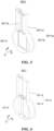
- FIG. 7 is a schematic view of a tray clamp according to some embodiments of the present application.
- the standing device 50 further comprises a tray clamp 60, and the tray clamp 60 is disposed on the conveying apparatus 505 and configured to place the battery cell 20.
- the tray clamp 60 is disposed on the conveying apparatus 505 and configured to place the battery cell 20.
- FIG. 8 is an enlarged schematic view of a region A in FIG. 7 .
- the tray clamp 60 comprises a liquid injection mechanism 61 and a liquid injection clamp 62.
- a liquid discharge port 610 of the liquid injection mechanism 61 is configured to align with a liquid injection port 210 of the battery cell 20, so as to inject an electrolyte into the battery cell 20.
- the liquid injection clamp 62 is configured to clamp the battery cell. In this way, during the standing process of the battery cell 20, the liquid injection mechanism 61 can also inject the electrolyte into the battery cell 20, so that the content of the electrolyte in the battery cell 20 can be increased.
- the tray clamp 60 may further comprise a mounting bracket 600, and the mounting bracket 600 comprises a first tray 63, a second tray 64, supports 65 for connecting the first tray 63 with the second tray 64, and a first tray reinforcing rib 631.
- the first tray 63 is provided with a mounting hole for carrying the liquid injection mechanism 61, and the first tray reinforcing rib 631 is configured to enhance the structural strength of the first tray 63.
- the second tray 64 is configured to carry the battery cell 20, and the liquid injection clamp 62 is configured to clamp and fix the battery cell 20.
- the liquid injection clamp 62 is configured to clamp and fix the battery cell 20, and a set of battery cells 20 can be clamped and fixed by a pair of liquid injection clamps 62 disposed oppositely.
- the liquid injection mechanism 61 may comprise a plurality of electrolyte buffer cups, wherein each electrolyte buffer cup is filled with an electrolyte for the corresponding battery cell 20, and the electrolyte in the electrolyte buffer cup can enter the liquid injection port 210 through the liquid discharge port 610.
- 30% to 50% of the electrolyte in the electrolyte buffer cup can be injected into the battery cell 20 through the liquid injection mechanism 61, and the remaining electrolyte can be gradually injected during the standing process of the battery cell 20 in the standing device 50.
- the battery cell 20 absorbs the electrolyte under the action of pressure, and simultaneously, the electrolyte is continuously injected into the battery cell 20, thus being beneficial for improving the level of absorbing the electrolyte by the battery cell 20, so as to increase the content of the electrolyte in the battery cell 20.
- an end of the liquid discharge port 610 close to the liquid injection port 210 is provided with a sealing member 611.
- the sealing member 611 may be a rubber sealing ring. In this way, the electrolyte can be prevented from leaking from a joint between the liquid discharge port 610 and the liquid injection port 210.
Landscapes
- Chemical & Material Sciences (AREA)
- Chemical Kinetics & Catalysis (AREA)
- Electrochemistry (AREA)
- General Chemical & Material Sciences (AREA)
- Engineering & Computer Science (AREA)
- Manufacturing & Machinery (AREA)
- Power Engineering (AREA)
- Secondary Cells (AREA)
- Battery Mounting, Suspending (AREA)
Abstract
Description
- The present application claims priority to
Chinese patent application 202220630077.7 filed on March 22, 2022 - The present application relates to the technical field of batteries, and more specifically, to a standing device.
- With the increasing severity of environmental pollution, the new energy industry is receiving more and more attention from people. The battery technology is an important factor related to the development of the new energy industry.
- In the existing production process of a battery cell, it is necessary to use a standing device to let the battery cell stand to fully soak electrode assemblies in the battery cell by an electrolyte. Therefore, how to provide a standing device which can reduce the energy consumption of the standing device while guaranteeing the performance of the battery cell is an urgent problem to be solved in the battery technology.
- An embodiment of the present application provides a standing device which can reduce the energy consumption of the standing device while guaranteeing the performance of a battery cell.
- According to a first aspect, a standing device is provided for letting a battery cell stand, comprising: a pressure regulating apparatus; a standing cavity; a charging cavity, connected to a first end of the standing cavity, the charging cavity being connected to the pressure regulating apparatus; a conveying apparatus, penetratingly disposed in the standing cavity and the charging cavity and configured to convey the battery cell; and a charging cavity sealing gate, disposed between the charging cavity and the standing cavity, the charging cavity sealing gate being configured to be opened when the pressure in the charging cavity rises to the pressure in the standing cavity, so that the battery cell is conveyed to the standing cavity.
- In the embodiment of the present application, the charging cavity is connected to the standing cavity. When the pressure in the charging cavity is raised to the same pressure in the standing cavity through the pressure regulating apparatus, the charging cavity sealing gate is opened, and the battery cell is conveyed from the charging cavity to the standing cavity through the conveying apparatus to stand. The battery cell which stands in a stable pressure environment has good consistency, and the performance of the battery cell can be guaranteed. After the pressure in the charging cavity is raised to the pressure in the standing cavity, the battery cell is moved into the standing cavity. In this way, during the process of conveying the battery cell from the charging cavity to the standing cavity, the pressure in the standing cavity will not change, so there is no need to supplement additional pressure to the standing cavity, which can reduce the energy consumption of the standing device. Therefore, by means of the technical solutions in the embodiments of the present application, the energy consumption of the standing device can be reduced while the performance of the battery cell is guaranteed.
- In a possible implementation, the charging cavity sealing gate is configured to be closed after the battery cell is conveyed to the standing cavity, and the charging cavity is configured to be depressurised after the charging cavity sealing gate is closed; and the standing device further comprises: a charging sealing cover, the charging sealing cover being disposed at an end of the charging cavity away from the standing cavity, and the charging sealing cover being configured to be opened after the pressure in the charging cavity is reduced, so as to put in the battery cell. In this way, the sealing performance between the standing cavity and the charging cavity can be guaranteed, and the reduction of pressure in the standing cavity caused by insufficient sealing during the pressure reduction process of the charging cavity can be prevented, so that the pressure in the standing cavity can be maintained to prevent the change in pressure in the standing cavity that may require additional energy to maintain the pressure in the standing cavity. After the pressure in the charging cavity is reduced, the pressure difference between the inside of the charging cavity and the outside of the standing device is smaller, thus facilitating the opening of the charging sealing cover.
- In a possible implementation, the standing device further comprises: a discharging cavity, connected to a second end of the standing cavity, the discharging cavity being connected to the pressure regulating apparatus; and a discharging cavity sealing gate, disposed between the standing cavity and the discharging cavity, the discharging cavity sealing gate being configured to be opened when the pressure in the discharging cavity rises to the pressure in the standing cavity, so as to convey the battery cell to the discharging cavity. In this way, during the process of conveying the battery cell from the standing cavity to the discharging cavity, the pressure in the standing cavity will not change, so there is no need to supplement additional pressure to the standing cavity, which can reduce the energy consumption of the standing device. Furthermore, after the standing of the battery cell in the standing cavity is completed, when the pressure in the discharging cavity is equal to the pressure in the standing cavity, it is only necessary to convey the battery cell from the standing cavity to the discharging cavity, close the discharging cavity sealing gate, and then remove the battery cell from the discharging cavity; and it is not necessary to remove the battery cell from the standing cavity after discharging the high pressure in the standing cavity, thus further reducing the energy consumption of the standing device.
- In a possible implementation, the discharging cavity sealing gate is configured to be closed after the battery cell is conveyed to the discharging cavity, and the discharging cavity is configured to be depressurised after the discharging cavity sealing gate is closed; and the standing device further comprises: a discharging sealing cover, the discharging sealing cover being disposed at an end of the discharging cavity away from the standing cavity, and the discharging sealing cover being configured to be opened after the pressure in the discharging cavity is reduced, so as to remove the battery cell. In this way, the sealing performance between the standing cavity and the discharging cavity can be guaranteed, and the reduction of pressure in the standing cavity caused by insufficient sealing during the pressure reduction process of the discharging cavity can be prevented, so that the pressure in the standing cavity can be maintained to prevent the change in pressure in the standing cavity that may require additional energy to maintain the pressure in the standing cavity. After the pressure in the discharging cavity is reduced, the pressure difference between the inside of the discharging cavity and the outside of the standing device is smaller, thus facilitating the opening of the discharging sealing cover.
- In a possible implementation, the standing device further comprises: a pressure recovery apparatus, the pressure recovery apparatus being in communication with the charging cavity and the discharging cavity respectively, so as to recover high pressure from one of the charging cavities and the discharging cavities to the other one. The pressure recovery apparatus can recover the high pressure in the charging cavity to the discharging cavity, and can also recover the high pressure in the discharging cavity to the charging cavity. In this way, the recovery and reuse of high-pressure gas can be achieved, and the energy consumption of the standing device can be reduced.
- In a possible implementation, the charging cavity sealing gate comprises: a gate body, the gate body being connected to the charging cavity and the standing cavity respectively, and the gate body being provided with a first opening in communication with the charging cavity and the standing cavity; and a gate plate, movably disposed on the gate body and corresponding to the first opening, and configured to open or close the first opening. When the battery cell is conveyed from the charging cavity to the standing cavity, the gate plate rises and is opened, so that the battery cell enters the standing cavity from the charging cavity through the first opening. After the battery cell enters the standing cavity, the gate plate descends and is closed to achieve the isolation and sealing between the charging cavity and the standing cavity, which can prevent pressure leakage from the standing cavity to the charging cavity, thus guaranteeing the pressure stability in the standing cavity.
- In a possible implementation, the conveying apparatus comprises a first sub-conveying apparatus and a second sub-conveying apparatus, and the first sub-conveying apparatus and the second sub-conveying apparatus are threaded in the charging cavity and the standing cavity respectively, wherein the first sub-conveying apparatus and the second sub-conveying apparatus are disposed at an interval to avoid the gate plate. The first sub-conveying apparatus and the second sub-conveying apparatus are disposed at an interval, that is, the first sub-conveying apparatus and the second sub-conveying apparatus are disposed separately. In this way, the gate plate can be disposed at a gap, so that the conveying apparatus can avoid the gate plate to guarantee the sealing between the gate plate and the first opening.
- In a possible implementation, the volume of the standing cavity is 1-20 times the volume of the charging cavity. In this way, compared to the standing cavity, the charging cavity with a smaller volume has a higher pressure rise speed and less energy consumption during pressure rise, so that the production efficiency can be accelerated, and the energy consumption can also be reduced. Furthermore, due to a longer standing time of the battery cell, the number of standing of battery cells can be increased by increasing the volume of the standing cavity, so as to accelerate the production efficiency.
- In a possible implementation, the standing cavity is a segmented structure. In this way, the number of segments of the standing cavity can be set according to actual needs, and the number of standing battery cells can be increased by increasing the number of segments of the standing cavity. Furthermore, because the volume of the standing cavity is related to the number of segments of the standing cavity, the number of segments of the standing cavity can be flexibly set according to the required standing time of the battery cell. In addition, when the size of each segment of the standing cavity is the same, it is also possible to achieve replacement instead of repair of the standing cavity to avoid the production pause caused by faults in the standing cavity, thus being beneficial for improving the production efficiency.
- In a possible implementation, the charging cavity and the standing cavity are cylindrical. In this way, forces applied in the charging cavity and the standing cavity are uniform. Compared to a square charging cavity and a square standing cavity, the cylindrical charging cavity and the cylindrical standing cavity require a smaller thickness on the premise of meeting strength, thus being beneficial for reducing the cost.
- In a possible implementation, the standing device further comprises: a tray clamp, disposed on the conveying apparatus and configured to place the battery cell. The battery cell can be conveyed and transported conveniently by disposing the tray clamp.
- In a possible implementation, the tray clamp comprises: a liquid injection mechanism, a liquid discharge port of the liquid injection mechanism being configured to align with a liquid injection port of the battery cell, so as to inject an electrolyte into the battery cell; and a liquid injection clamp, the liquid injection clamp being configured to clamp the battery cell and the liquid injection mechanism. In this way, during the standing process of the battery cell, the liquid injection mechanism can continue to inject the electrolyte into the battery cell, so that the content of the electrolyte in the battery cell can be increased.
- In a possible implementation, an end of the liquid discharge port close to the liquid injection port is provided with a sealing member. In this way, the electrolyte can be prevented from leaking from a joint between the liquid discharge port and the liquid injection port.
- In the embodiment of the present application, the charging cavity is connected to the standing cavity. When the pressure in the charging cavity is raised to the same pressure in the standing cavity through the pressure regulating apparatus, the charging cavity sealing gate is opened, and the battery cell is conveyed from the charging cavity to the standing cavity through the conveying apparatus to stand. In this way, the battery cell which stands in a stable pressure environment has good consistency, and the performance of the battery cell can be guaranteed. After the pressure in the charging cavity is raised to the pressure in the standing cavity, the battery cell is moved into the standing cavity. In this way, during the process of conveying the battery cell from the charging cavity to the standing cavity, the pressure in the standing cavity will not change, so there is no need to supplement additional pressure to the standing cavity, which can reduce the energy consumption of the standing device. Therefore, by means of the technical solutions in the embodiments of the present application, the energy consumption of the standing device can be reduced while the performance of the battery cell is guaranteed.
- In order to illustrate the technical solutions in the embodiments of the present application more clearly, the following briefly introduces the drawings required in the embodiments of the present application. It will be apparent that the drawings described below are only some embodiments of the present application. For those of ordinary skill in the art, other drawings can also be obtained according to these drawings without any creative effort.
-
FIG. 1 is a schematic view of a standing device according to some embodiments of the present application; -
FIG. 2 is a cross-sectional view of the standing device according to some embodiments of the present application; -
FIG. 3 is a schematic view of a conveying apparatus according to some embodiments of the present application; -
FIG. 4 is a schematic view of a charging cavity sealing gate according to some embodiments of the present application; -
FIG. 5 is a schematic view of the charging cavity sealing gate inFIG. 4 when being opened along a direction C-C; -
FIG. 6 is a schematic view of the charging cavity sealing gate inFIG. 4 when being closed along the direction C-C; -
FIG. 7 is a schematic view of a tray clamp according to some embodiments of the present application; and -
FIG. 8 is a schematic enlarged view of a region A inFIG. 7 . - Technical solutions in the embodiments of the present application are described below with reference to the drawings.
- The implementations of the present application are further described in detail below with reference to the drawings and embodiments. The following detailed description of the embodiments and the drawings are used to illustrate the principles of the present application by way of example, but should not be used to limit the scope of the present application, that is, the present application is not limited to the described embodiments.
- In the description of the present application, it should be noted that unless otherwise stated, all technical and scientific terms used herein have the same meanings as commonly understood by those skilled in the art of the present application. The terms used herein are intended only for the purpose of describing specific embodiments and are not intended to limit the present application. The terms "comprise" and "have" and any variations thereof in the specification and claims of the present application as well as in the above description of drawings are intended to cover a non-exclusive inclusion; the term "a plurality of" means two or more; and the orientation or position relationships indicated by the terms "upper", "lower", "left", "right", "inner", "outer", and the like are only for facilitating the description of the present application and simplifying the description, rather than indicating or implying that the apparatus or element referred to must have a specific orientation or be constructed and operated in a specific orientation, and therefore will not be interpreted as limiting the present application. In addition, the terms "first", "second", "third", and the like are used for descriptive purposes only, and cannot be construed as indicating or implying relative importance. "Vertical" is not strictly vertical, but within an allowable range of an error. "Parallel" is not strictly parallel, but within an allowable range of an error.
- The reference to "embodiments" in the present application means that specific features, structures, or characteristics described with reference to embodiments may be included in at least one embodiment of the present application. The appearance of this phrase in various places in the specification does not necessarily refer to the same embodiment, nor is it a separate or alternative embodiment that is mutually exclusive with other embodiments. It is explicitly and implicitly understood by those skilled in the art that the embodiments described in the present application may be combined with other embodiments.
- Orientation words appearing in the following description are all directions shown in the drawings, and do not limit the specific structure of the present application. In the description of the present application, it should also be noted that unless otherwise expressly specified and defined, the terms "install", "connected" and "connect" should be understood in a broad sense. For example, the connection may be fixed connection, detachable connection, or integrated connection, or may be direct connection, indirect connection through an intermediate, or internal communication of two elements. Those of ordinary skill in the art can understand the specific meanings of the above terms in the present application according to specific situations.
- In the present application, the term "and/or" only describes an association relationship between associated objects and represents that three relationships may exist. For example, A and/or B may represent three situations: A exists alone, both A and B exist, and B exists alone. In addition, the character "/" in the present application generally means that the associated objects before and after it are in an "or" relationship.
- In the existing production processes of a battery cell, after an electrode assembly is made. Processes, such as liquid injection, standing, and formation, need to be performed to form a final battery cell. The standing of the battery cell is a very important technological operation. After standing, the electrode assembly can be fully soaked by an electrolyte to increase the consistency of a subsequent formation interface, thus improving the performance of the battery cell. In this way, a standing device is crucial for the standing of the battery cell, but the standing device often generates higher energy consumption. Therefore, how to reduce the energy consumption of the standing device while guaranteeing the performance of the battery cell is an urgent problem to be solved.
- In view of this, an embodiment of the present application provides a standing device for letting a battery cell stand. The standing device comprises a charging cavity and a standing cavity, wherein the charging cavity is connected to the standing cavity. When the pressure in the charging cavity is raised to the same pressure in the standing cavity through a pressure regulating apparatus, a charging cavity sealing gate is opened, and the battery cell is conveyed from the charging cavity to the standing cavity through a conveying apparatus to stand. In this way, the battery cell which stands in a stable pressure environment has good consistency, and the performance of the battery cell can be guaranteed. After the pressure in the charging cavity is raised to the pressure in the standing cavity, the battery cell is moved into the standing cavity. In this way, during the process of conveying the battery cell from the charging cavity to the standing cavity, the pressure in the standing cavity will not change, so there is no need to supplement additional pressure to the standing cavity, which can reduce the energy consumption of the standing device. Therefore, by means of the technical solutions in the embodiments of the present application, the energy consumption of the standing device can be reduced while the performance of the battery cell is guaranteed.
-
FIG. 1 shows a structural schematic view of a standing device according to some embodiments of the present application, andFIG. 2 shows a schematic view of a cross-sectional structure of the standing device according to some embodiments of the present application. The standingdevice 50 is configured to let abattery cell 20 stand. As shown inFIG. 1 and FIG. 2 , the standingdevice 50 comprises: apressure regulating apparatus 51; a standingcavity 502; a chargingcavity 501, connected to a first end of the standingcavity 502, the chargingcavity 501 being connected to thepressure regulating apparatus 51; a conveyingapparatus 505, penetratingly disposed in the standingcavity 502 and the chargingcavity 501 and configured to convey thebattery cell 20; and a chargingcavity sealing gate 5011, disposed between the chargingcavity 501 and the standingcavity 502, the chargingcavity sealing gate 5011 being configured to be opened when the pressure in the chargingcavity 501 rises to the pressure in the standingcavity 502, so that thebattery cell 20 is conveyed to the standingcavity 502. - The
battery cell 20 may comprise a lithium-ion secondary battery, a lithium-ion primary battery, a lithium-sulphur battery, a sodium/lithium-ion battery, a sodium-ion battery, a magnesium-ion battery, or the like, which is not limited in the embodiments of the present application. Thebattery cell 20 may be cylindrical, flat, rectangular, or in other shapes, which is also not limited in the embodiments of the present application. Thebattery cell 20 may be divided into a cylindrical battery cell, a square battery cell, or a pouch cell according to an encapsulating manner, which is also not limited in the embodiments of the present application. - The
pressure regulating apparatus 51 is a device for regulating pressure. In some embodiments, thepressure regulating apparatus 51 may be configured to regulate the pressure of the standingdevice 50. Specifically, thepressure regulating apparatus 51 may be connected to the chargingcavity 501 through afirst pipeline 511 to regulate the pressure in the chargingcavity 501. Optionally, thepressure regulating apparatus 51 may be an air compressor. - The standing
cavity 502 is configured to let thebattery cell 20 stand. In some embodiments, before the standingdevice 50 operates, the pressure in the standingcavity 502 is P0. During the initial operation phase of the standingdevice 50, thepressure regulating apparatus 51 supplements pressure to the standingcavity 502, so that the pressure in the standingcavity 502 reaches the target pressure P1, wherein the value of P1 may be regulated according to actual needs. For example, P1 may be 1.2 MPa, and P0 may be standard atmospheric pressure. After the official operation of the standingdevice 50, the pressure in the standingcavity 502 is maintained at P1, and at this time, thebattery cell 20 can stand in the standingcavity 502. Because the pressure in the standingcavity 502 is maintained at P1, in this way, thebattery cell 20 stands under stable pressure, which can guarantee that eachbattery cell 20 absorbs the electrolyte to the same extent, so as to be beneficial for improving the consistency of the battery or battery cell 10. - The charging
cavity 501 is connected to the first end of the standingcavity 502, and the first end may be an end of the standingcavity 502 close to the chargingcavity 501 along the conveying direction of thebattery cell 20. -
FIG. 3 is a structural schematic view of a conveying apparatus according to some embodiments of the present application. With reference toFIG. 2 andFIG. 3 , the conveyingapparatus 505 is penetratingly disposed between the chargingcavity 501 and the standingcavity 502 and may be configured to convey thebattery cell 20. Optionally, the conveyingapparatus 505 may be a roller-shaped conveying apparatus extending along an x direction, that is, the conveyingapparatus 505 is composed of a plurality of roller-shaped units. - In the embodiments of the present application, the charging
cavity 501 is connected to the standingcavity 502. When the pressure in the chargingcavity 501 is raised to the same pressure in the standingcavity 502 through thepressure regulating apparatus 51, the chargingcavity sealing gate 5011 is opened, and thebattery cell 20 is conveyed from the chargingcavity 501 to the standingcavity 502 through the conveying apparatus to stand. In this way, thebattery cell 20 has good consistency, and the performance of thebattery cell 20 can be guaranteed. After the pressure in the chargingcavity 501 is raised to the pressure in the standingcavity 502, thebattery cell 20 is moved into the standingcavity 502. In this way, during the process of conveying thebattery cell 20 from the chargingcavity 501 to the standingcavity 502, the pressure in the standingcavity 502 will not change, so there is no need to supplement additional pressure to the standingcavity 502, which can reduce the energy consumption of the standingdevice 50. Therefore, by means of the technical solutions in the embodiments of the present application, the energy consumption of the standingdevice 50 can be reduced while the performance of thebattery cell 20 is guaranteed. - Optionally, in some embodiments of the present application, the charging
cavity sealing gate 5011 is configured to be closed after thebattery cell 20 is conveyed to the standingcavity 502, and the chargingcavity 501 is configured to be depressurised after the chargingcavity sealing gate 5011 is closed; and the standingdevice 50 further comprises: a chargingsealing cover 5012, thecharging sealing cover 5012 being disposed at an end of the chargingcavity 501 away from the standingcavity 502, and thecharging sealing cover 5012 being configured to be opened after the pressure in the chargingcavity 501 is reduced, so as to put in thebattery cell 20. - After the
battery cell 20 is conveyed from the chargingcavity 501 to the standingcavity 502, the chargingcavity sealing gate 5011 is closed, and the pressure in the chargingcavity 501 is reduced. In this way, the leakage of high pressure in the standingcavity 502 caused by insufficient sealing between the chargingcavity 501 and the standingcavity 502 can be prevented, so that the pressure in the standingcavity 502 can be maintained to avoid the energy loss caused by additional supplementation of pressure to the standingcavity 502. - After the charging
cavity sealing gate 5011 is closed, the pressure in the chargingcavity 501 is reduced. In some embodiments, the pressure in the chargingcavity 501 may be reduced continuously after thecharging sealing cover 5012 is opened. For example, part of the high pressure in the chargingcavity 501 is discharged before thecharging sealing cover 5012 is opened; and after thecharging sealing cover 5012 is opened, the high pressure in the chargingcavity 501 is completely discharged, and the pressure in the chargingcavity 501 is reduced to normal pressure. In some other embodiments, the chargingcavity 501 may be provided with an exhaust port; after the chargingcavity sealing gate 5011 is closed, the high pressure in the chargingcavity 501 may be completely discharged through the exhaust port, so that the pressure in the chargingcavity 501 is reduced to normal pressure, wherein part of the high pressure in the chargingcavity 501 may be discharged first through other apparatuses, and then, the remaining high pressure is discharged through the exhaust port; and the high pressure in the chargingcavity 501 may also be completely discharged only through the exhaust port until the pressure in the chargingcavity 501 is reduced to normal pressure. The embodiments of the present application do not impose specific restrictions on this. - The
charging sealing cover 5012 is opened when thebattery cell 20 enters the chargingcavity 501 and is closed after thebattery cell 20 enters the chargingcavity 501, thus being convenient to increase the pressure in the chargingcavity 501. When the pressure in the chargingcavity 501 rises to the pressure in the standingcavity 502, the chargingcavity sealing gate 5011 is opened, and thebattery cell 20 enters the standingcavity 502 from the chargingcavity 501, and after thebattery cell 20 enters the standingcavity 502, the chargingcavity sealing gate 5011 is closed. At this time, in some embodiments, at least part of the high pressure in the chargingcavity 501 is discharged, thecharging sealing cover 5012 is opened, and the pressure in the chargingcavity 501 is further reduced to normal pressure; and after the pressure in the chargingcavity 501 is reduced to normal pressure, the next set ofbattery cells 20 are put in the chargingcavity 501 to let the next set ofbattery cells 20 stand. In some other embodiments, at least part of the high pressure in the chargingcavity 501 is discharged, and the remaining high pressure in the chargingcavity 501 is discharged out of the chargingcavity 501 through the exhaust port, and after the pressure in the chargingcavity 501 is reduced to normal pressure, thecharging sealing cover 5012 is opened, and the next set ofbattery cells 20 are put in the chargingcavity 501 to let the next set ofbattery cells 20 stand. - Optionally, in some embodiments of the present application, the standing
device 50 further comprises: a dischargingcavity 503, connected to a second end of the standingcavity 502, the dischargingcavity 503 being connected to thepressure regulating apparatus 51, and a dischargingcavity sealing gate 5031, disposed between the standingcavity 502 and the dischargingcavity 503, the dischargingcavity sealing gate 5031 being configured to be opened when the pressure in the dischargingcavity 503 rises to the pressure in the standingcavity 502, so as to convey thebattery cell 20 to the dischargingcavity 503. - The discharging
cavity 503 is connected to the second end of the standingcavity 502, and the second end may be an end of the standingcavity 502 away from the chargingcavity 501 along the conveying direction of thebattery cell 20. - The
pressure regulating apparatus 51 may also be connected to the dischargingcavity 503 through a second pipeline 512 to regulate the pressure in the dischargingcavity 503, for example, to increase the pressure in the dischargingcavity 503. - The discharging
cavity sealing gate 5031 is disposed between the standingcavity 502 and the dischargingcavity 503. When the pressure in the dischargingcavity 503 rises to the same pressure in the standingcavity 502, the dischargingcavity sealing gate 5031 is opened to enable thebattery cell 20 to be removed to the standingcavity 502. In this way, the pressure in the standingcavity 502 is the same as the pressure in the dischargingcavity 503. When the dischargingcavity sealing gate 5031 is opened, the pressure in the standingcavity 502 will not change. Furthermore, after the standing of thebattery cell 20 is completed, it is only necessary to convey thebattery cell 20 from the standingcavity 502 to the dischargingcavity 503, close the dischargingcavity sealing gate 5031, and then remove thebattery cell 20 from the dischargingcavity 503. The pressure in the standingcavity 502 cannot be changed, the pressure in the standingcavity 502 can be always in a stable state, and there is no need for additional energy to increase the pressure in the standingcavity 502 after the pressure in the standingcavity 502 is reduced, thus further reducing the energy consumption. - Optionally, in some embodiments of the present application, the discharging
cavity sealing gate 5031 is configured to be closed after thebattery cell 20 is conveyed to the dischargingcavity 503, and the dischargingcavity 503 is configured to be depressurised after the dischargingcavity sealing gate 5031 is closed; and the standingdevice 50 further comprises: a dischargingsealing cover 5032, the dischargingsealing cover 5032 being disposed at an end of the dischargingcavity 503 away from the standingcavity 502, and the dischargingsealing cover 5032 being configured to be opened after the pressure in the dischargingcavity 503 is reduced, so as to remove thebattery cell 20. In this way, the leakage of high pressure in the standingcavity 502 caused by removal of thebattery cell 20 from the dischargingcavity 503 can be avoided. - After the
battery cell 20 is conveyed from the standingcavity 502 to the dischargingcavity 503, the dischargingcavity sealing gate 5031 is closed, and the pressure in the dischargingcavity 503 is reduced. In this way, the leakage of high pressure in the standingcavity 502 caused by insufficient sealing between the dischargingcavity 503 and the standingcavity 502 can be prevented, so that the pressure in the standingcavity 502 can be maintained to avoid the energy loss caused by additional supplementation of pressure to the standingcavity 502. - After the discharging
cavity sealing gate 5031 is closed, the pressure in the dischargingcavity 503 is reduced. In some embodiments, the pressure in the dischargingcavity 503 may be reduced continuously after the dischargingsealing cover 5032 is opened. For example, part of the high pressure in the dischargingcavity 503 is discharged before the dischargingsealing cover 5032 is opened, and after the dischargingsealing cover 5032 is opened, the high pressure in the dischargingcavity 503 is completely discharged, and the pressure in the dischargingcavity 503 is reduced to normal pressure. In some other embodiments, the dischargingcavity 503 may be provided with a gas outlet; after the dischargingcavity sealing gate 5031 is closed, the high pressure in the dischargingcavity 503 may be completely discharged through the gas outlet, so that the pressure in the dischargingcavity 503 is reduced to normal pressure, wherein part of the high pressure in the dischargingcavity 503 may be discharged first through other apparatuses, and then, the remaining high pressure is discharged through the gas outlet, and the high pressure in the dischargingcavity 503 may also be completely discharged only through the gas outlet until the pressure in the dischargingcavity 503 is reduced to normal pressure. The embodiments of the present application do not impose specific restrictions on this. - The discharging
sealing cover 5032 is configured to be opened after the pressure in the dischargingcavity 503 is reduced. At this time, the pressure difference between the inside of the dischargingcavity 503 and the outside of the standingdevice 50 is smaller, or the internal pressure of the dischargingcavity 503 is the same as the external pressure of the standingdevice 50, thus facilitating the opening of the dischargingsealing cover 5032. After the dischargingsealing cover 5032 is opened, thebattery cell 20 after standing is removed from the dischargingcavity 503. - Optionally, in some embodiments of the present application, the standing
device 50 further comprises apressure recovery apparatus 53. Thepressure recovery apparatus 53 is in communication with the chargingcavity 501 and the dischargingcavity 503 respectively, so as to recover high pressure from one of the chargingcavities 501 and the dischargingcavities 503 to the other one. - Optionally, during the charging process of the
battery cell 20, after thebattery cell 20 is put in the chargingcavity 501, thecharging sealing cover 5012 is closed, thepressure regulating apparatus 51 regulates the pressure in the chargingcavity 501 to be consistent with the pressure in the standingcavity 502, and at this time, the chargingcavity sealing gate 5011 is opened to convey thebattery cell 20 to the standingcavity 502. Thepressure recovery apparatus 53 is configured to recover the pressure in the chargingcavity 501 to the dischargingcavity 503 after thebattery cell 20 is moved from the chargingcavity 501 to the standingcavity 502 and the chargingcavity sealing gate 5011 is closed, so as to increase the pressure in the dischargingcavity 503, and reduce the energy consumption required for the pressure rise of the dischargingcavity 503 when thebattery cell 20 is moved from the standingcavity 502 to the dischargingcavity 503. On the one hand, the pressure in the chargingcavity 501 can be reduced from P1 to P2 through thepressure recovery apparatus 53 to facilitate the opening of thecharging sealing cover 5011, and the next set ofbattery cells 20 are put in the chargingcavity 501 to let the next set ofbattery cells 20 stand. Alternatively, the pressure in the dischargingcavity 503 can be increased from P0 to P2 through thepressure recovery apparatus 53, and at this time, thepressure regulating apparatus 51 supplements pressure to the dischargingcavity 503 to enable the pressure in the dischargingcavity 503 to be the same as the pressure in the standingcavity 502, so that the energy consumption of thepressure regulating apparatus 51 can be reduced. In this way, the recovery and reuse of the high pressure in the chargingcavity 501 are achieved, and thepressure regulating apparatus 51 does not need to increase the pressure in the dischargingcavity 503 from P0 to P1, thus further reducing the energy consumption. - Optionally, during the discharging process of the
battery cell 20, thepressure regulating apparatus 51 regulates the pressure in the dischargingcavity 503 to be consistent with the pressure in the standingcavity 502, and at this time, the dischargingcavity sealing gate 5031 is opened to convey thebattery cell 20 to the dischargingcavity 503. Thepressure recovery apparatus 53 is configured to recover the pressure in the dischargingcavity 503 to the chargingcavity 501 after thebattery cell 20 is moved from the standingcavity 502 to the dischargingcavity 503 and the dischargingcavity sealing gate 5031 is closed, so as to increase the pressure in the chargingcavity 501, and reduce the energy consumption required for the pressure rise of the chargingcavity 501 when thebattery cell 20 is conveyed from the chargingcavity 501 to the standingcavity 502. On the one hand, the pressure in the dischargingcavity 503 can be reduced from P1 to P3 through thepressure recovery apparatus 53 to facilitate the opening of the dischargingsealing cover 5031, and thebattery cell 20 after standing is removed from the dischargingcavity 503. Alternatively, the pressure in the chargingcavity 501 can be increased from P0 to P3 through thepressure recovery apparatus 53, and at this time, thepressure regulating apparatus 51 supplements pressure to the chargingcavity 501 to enable the pressure in the chargingcavity 501 to be the same as the pressure in the standingcavity 502, so that the energy consumption of thepressure regulating apparatus 51 can be reduced. In this way, the recovery and reuse of the high pressure in the dischargingcavity 503 are achieved, and thepressure regulating apparatus 51 does not need to increase the pressure in the chargingcavity 501 from P0 to P1, thus further reducing the energy consumption. - Optionally, the
pressure recovery apparatus 53 may be a pressure recovery pipeline, and the pressure recovery pipeline is provided with a valve. When the valve is opened, the high pressure in the chargingcavity 501 may enter the dischargingcavity 503 through the pressure recovery pipeline, or the high pressure in the dischargingcavity 503 may enter the chargingcavity 501 through the pressure recovery pipeline, thus achieving the recovery and reuse of high-pressure gas. By disposing the pressure recovery pipeline, spontaneous balance of pressure in the chargingcavity 501 and the dischargingcavity 503 can be achieved, and the recovery and reuse of high pressure can be achieved without the need for additional power. -
FIG. 4 is a structural schematic view of a charging cavity sealing gate according to some embodiments of the present application;FIG. 5 is a structural schematic view of the charging cavity sealing gate inFIG. 4 when being opened along a direction C-C; andFIG. 6 is a structural schematic view of the charging cavity sealing gate inFIG. 4 when being closed along the direction C-C. Optionally, in some embodiments of the present application, with reference toFIG. 4 to FIG. 6 , the chargingcavity sealing gate 5011 comprises agate body 5011a and agate plate 5011b. Thegate body 5011a is connected to the chargingcavity 501 and the standingcavity 502 respectively, and thegate body 5011a is provided with afirst opening 5011c in communication with the chargingcavity 501 and the standingcavity 502. Thegate plate 5011b is movably disposed on thegate body 5011a and corresponds to thefirst opening 5011c, and is configured to open or close thefirst opening 5011c. - In some embodiments, the
gate body 5011a may comprise amain body part 5011e and aprotruding part 5011d which are connected to each other. The protrudingpart 5011d protrudes from themain body part 5011e along a radial direction of themain body part 5011e, and theprotruding part 5011d is configured to accommodate thegate plate 5011b when the chargingcavity sealing gate 5011 is opened, so as to prevent dust on thegate plate 5011b from causing jamming when thegate plate 5011b is moved or affecting the sealing performance between thegate plate 5011b and thefirst opening 5011c. The diameter of themain body part 5011e is greater than the diameter of the chargingcavity 501 and the diameter of the standingcavity 502. Themain body part 5011e of thegate body 5011a sleeves the chargingcavity 501 and the standingcavity 502, so as to connect the chargingcavity 501 and the standingcavity 502. Of course, in some other embodiments, themain body part 5011e of thegate body 5011a may also be connected to the chargingcavity 501 and the standingcavity 502 by means of bolted connection, welding, or the like. - The
gate plate 5011b is movably disposed on thegate body 5011a, and thegate plate 5011b can move along the radial direction of themain body part 5011e of thegate body 5011a to open or close thefirst opening 5011c. For example, in some embodiments, thegate plate 5011b can move relative to thegate body 5011a along the conveying direction perpendicular to thebattery cell 20, namely the x direction, so as to open or close thefirst opening 5011c. In some other embodiments, thegate plate 5011b can move up and down relative to thegate body 5011a along a vertical direction, for example, a z direction, so as to open or close thefirst opening 5011c. - In some embodiments, the
gate plate 5011b may be connected to a driving apparatus. Under the driving of the driving apparatus, when the chargingcavity sealing gate 5011 is opened, thegate plate 5011b moves along the radial direction of themain body part 5011e of thegate body 5011a and is accommodated in theprotruding part 5011d, so as to achieve the communication between the chargingcavity 501 and the standingcavity 502, and thebattery cell 20 can enter the standingcavity 502 through thefirst opening 5011c. When the chargingcavity sealing gate 5011 is closed, thegate plate 5011b is reset and can completely seal thefirst opening 5011c, so as to achieve the sealing between the chargingcavity 501 and the standingcavity 502. - Optionally, the size of the
gate plate 5011b may be greater than or equal to the size of thefirst opening 5011c, wherein thegate plate 5011b may be square, circular, or the like, and correspondingly, thefirst opening 5011c is also square, circular, or the like. - Optionally, in an embodiment of the present application, the discharging
cavity sealing gate 5031 comprises a discharging cavity gate body and a discharging cavity gate plate, and the discharging cavity gate body and the discharging cavity gate plate may have the same structures as thegate body 5011a and the gate plate of the chargingcavity sealing gate 5011, and are not repeated in the embodiment of the present application. - Optionally, in an embodiment of the present application, the conveying
apparatus 505 comprises a firstsub-conveying apparatus 5051 and a secondsub-conveying apparatus 5052, and the firstsub-conveying apparatus 5051 and the secondsub-conveying apparatus 5052 are threaded in the chargingcavity 501 and the standingcavity 502 respectively, wherein the firstsub-conveying apparatus 5051 and the secondsub-conveying apparatus 5052 are disposed at an interval to avoid thegate plate 5011a. The firstsub-conveying apparatus 5051 and the secondsub-conveying apparatus 5052 are disposed separately, that is, the firstsub-conveying apparatus 5051 and the secondsub-conveying apparatus 5052 are disposed at an interval. In this way, thegate plate 5011b can be disposed at a gap, so that thegate plate 5011b can seal thefirst opening 5011c, thus achieving the sealing function of the chargingcavity sealing gate 5011. Therefore, by disposing the firstsub-conveying apparatus 5051 and the secondsub-conveying apparatus 5052 at an interval, the avoidance of thegate plate 5011b of thegate body 5011a is achieved, and the sealing between thegate plate 5011b and thefirst opening 5011c can be guaranteed. - Optionally, the conveying
apparatus 505 further comprises a thirdsub-conveying apparatus 5053, the thirdsub-conveying apparatus 5053 is threaded in the dischargingcavity 503, and the secondsub-conveying apparatus 5052 and the thirdsub-conveying apparatus 5053 are disposed at an interval, so as to achieve the avoidance of the discharging cavity gate body to guarantee the sealing performance of the dischargingcavity sealing gate 5031. - Optionally, the conveying
apparatus 505 in the standingdevice 50 may be a multilayer structure. For example, with reference toFIG. 5 and FIG. 6 , the standingdevice 50 comprises two layers of conveyingapparatuses 505 along a z direction. By disposing multiple layers of conveyingapparatuses 505, the number of standingbattery cells 20 in the standingdevice 50 can be increased. - Optionally, in some embodiments of the present application, the volume of the standing
cavity 502 is 1-20 times the volume of the chargingcavity 501. On the one hand, compared to the standingcavity 502, the chargingcavity 501 with a smaller volume has a higher speed for increasing the pressure to P1 and less energy consumed by increasing the pressure, so that the production efficiency can be accelerated, and the energy consumption can also be reduced. Alternatively, when thebattery cell 20 requires a longer standing time, the standingcavity 502 can accommodatemore battery cells 20 by increasing the volume of the standingcavity 502, thus accelerating the production efficiency. - Optionally, in an embodiment of the present application, the standing
cavity 502 is a segmented structure. For example, the volume of the chargingcavity 501 is V1, the volume of the standingcavity 502 is n*V1, and the standingcavity 502 and the chargingcavity 501 have the same cross-sectional area, wherein n represents the number of segments of the standingcavity 502. In this way, the number of segments of the standingcavity 502 can be set according to actual needs. When thebattery cell 20 requires a shorter standing time, the volume of the standingcavity 502 can be reduced by reducing the number of segments of the standingcavity 502; and when thebattery cell 20 requires a longer standing time, the volume of the standingcavity 502 can be increased by increasing the number of segments of the standingcavity 502, thus meeting the requirements of thebattery cell 20 for different standing times. In addition, when a segment of the standingcavity 502 has a fault, due to the same volume and cross-sectional area of each standingcavity 502, the standingcavity 502 can be quickly replaced with a new standingcavity 502 to achieve replacement instead of repair to avoid the production pause caused by the fault in the standingcavity 502, thus being beneficial for improving the production efficiency. - Optionally, in an embodiment of the present application, the charging
cavity 501 and the standingcavity 502 are cylindrical. In this way, forces applied in the chargingcavity 501 and the standingcavity 502 are uniform. Compared to a square chargingcavity 501 and a square standingcavity 502, the cylindrical chargingcavity 501 and the cylindrical standingcavity 502 require a smaller thickness on the premise of meeting strength, thus being beneficial for reducing the cost. - Optionally, the discharging
cavity 503 is also cylindrical, that is, the entire cavity of the standingdevice 50 is cylindrical. - Optionally, the standing
device 50 is disposed horizontally, so the standingdevice 50 can save the space in a height direction. Furthermore, compared to vertical disposition, the energy consumption for conveying thebattery cell 20 by the conveying apparatus can also be further reduced. -
FIG. 7 is a schematic view of a tray clamp according to some embodiments of the present application. Optionally, as shown inFIG. 7 , in some embodiments of the present application, the standingdevice 50 further comprises atray clamp 60, and thetray clamp 60 is disposed on the conveyingapparatus 505 and configured to place thebattery cell 20. By placing thebattery cell 20 on thetray clamp 60 and placing thetray clamp 60 on the conveyingapparatus 505, the movement of thebattery cell 20 in the standingdevice 50 is achieved, that is, thebattery cell 20 can be conveyed and transported conveniently by disposing thetray clamp 60. -
FIG. 8 is an enlarged schematic view of a region A inFIG. 7 . Optionally, in some embodiments of the present application, with reference toFIG. 7 and FIG. 8 , thetray clamp 60 comprises aliquid injection mechanism 61 and aliquid injection clamp 62. Aliquid discharge port 610 of theliquid injection mechanism 61 is configured to align with aliquid injection port 210 of thebattery cell 20, so as to inject an electrolyte into thebattery cell 20. Theliquid injection clamp 62 is configured to clamp the battery cell. In this way, during the standing process of thebattery cell 20, theliquid injection mechanism 61 can also inject the electrolyte into thebattery cell 20, so that the content of the electrolyte in thebattery cell 20 can be increased. - Optionally, the
tray clamp 60 may further comprise a mountingbracket 600, and the mountingbracket 600 comprises afirst tray 63, asecond tray 64, supports 65 for connecting thefirst tray 63 with thesecond tray 64, and a firsttray reinforcing rib 631. Thefirst tray 63 is provided with a mounting hole for carrying theliquid injection mechanism 61, and the firsttray reinforcing rib 631 is configured to enhance the structural strength of thefirst tray 63. Thesecond tray 64 is configured to carry thebattery cell 20, and theliquid injection clamp 62 is configured to clamp and fix thebattery cell 20. By disposing the mountingbracket 600, theliquid injection mechanism 61 and thebattery cell 20 can be fixed on the mountingbracket 600 to form a whole, thus being convenient for transporting and conveying. - Optionally, the
liquid injection clamp 62 is configured to clamp and fix thebattery cell 20, and a set ofbattery cells 20 can be clamped and fixed by a pair of liquid injection clamps 62 disposed oppositely. - The
liquid injection mechanism 61 may comprise a plurality of electrolyte buffer cups, wherein each electrolyte buffer cup is filled with an electrolyte for thecorresponding battery cell 20, and the electrolyte in the electrolyte buffer cup can enter theliquid injection port 210 through theliquid discharge port 610. Optionally, before thebattery cell 20 enters the standingdevice 50, 30% to 50% of the electrolyte in the electrolyte buffer cup can be injected into thebattery cell 20 through theliquid injection mechanism 61, and the remaining electrolyte can be gradually injected during the standing process of thebattery cell 20 in the standingdevice 50. In this way, thebattery cell 20 absorbs the electrolyte under the action of pressure, and simultaneously, the electrolyte is continuously injected into thebattery cell 20, thus being beneficial for improving the level of absorbing the electrolyte by thebattery cell 20, so as to increase the content of the electrolyte in thebattery cell 20. - Optionally, in some embodiments of the present application, as shown in
FIG. 8 , an end of theliquid discharge port 610 close to theliquid injection port 210 is provided with a sealingmember 611. For example, the sealingmember 611 may be a rubber sealing ring. In this way, the electrolyte can be prevented from leaking from a joint between theliquid discharge port 610 and theliquid injection port 210. - Although the present application has been described with reference to the preferred embodiments, various improvements may be made, and components therein may be replaced with equivalents without departing from the scope of the present application. In particular, the technical features mentioned in the embodiments can be combined in any manner as long as there is no structural conflict. The present application is not limited to the specific embodiments disclosed herein, but rather includes all technical solutions falling within the scope of the claims.
Claims (13)
- A standing device for letting a battery cell (20) stand, comprising:a pressure regulating apparatus (51);a standing cavity (502);a charging cavity (501), connected to a first end of the standing cavity (502), the charging cavity (501) being connected to the pressure regulating apparatus (51);a conveying apparatus (505), penetratingly disposed in the standing cavity (502) and the charging cavity (501) and configured to convey the battery cell (20); anda charging cavity sealing gate (5011), disposed between the charging cavity (501) and the standing cavity (502), the charging cavity sealing gate (5011) being configured to be opened when the pressure in the charging cavity (501) rises to the pressure in the standing cavity (502), so that the battery cell (20) is conveyed to the standing cavity (502).
- The standing device according to claim 1, wherein the charging cavity sealing gate (5011) is configured to be closed after the battery cell (20) is conveyed to the standing cavity (502), and the charging cavity (501) is configured to be depressurised after the charging cavity sealing gate (5011) is closed; and the standing device (50) further comprises:
a charging sealing cover (5012), the charging sealing cover (5012) being disposed at an end of the charging cavity (501) away from the standing cavity (502), and the charging sealing cover (5012) being configured to be opened after the pressure in the charging cavity (501) is reduced, so as to put in the battery cell (20). - The standing device according to claim 1, wherein the standing device (50) further comprises:a discharging cavity (503), connected to a second end of the standing cavity (502), the discharging cavity (503) being connected to the pressure regulating apparatus (51); anda discharging cavity sealing gate (5031), disposed between the standing cavity (502) and the discharging cavity (503), the discharging cavity sealing gate (5031) being configured to be opened when the pressure in the discharging cavity (503) rises to the pressure in the standing cavity (502), so as to convey the battery cell (20) to the discharging cavity (503).
- The standing device according to claim 3, wherein the discharging cavity sealing gate (5031) is configured to be closed after the battery cell (20) is conveyed to the discharging cavity (503), and the discharging cavity (503) is configured to be depressurised after the discharging cavity sealing gate (5031) is closed; and the standing device (50) further comprises:
a discharging sealing cover (5032), the discharging sealing cover (5032) being disposed at an end of the discharging cavity (503) away from the standing cavity (502), and the discharging sealing cover (5032) being configured to be opened after the pressure in the discharging cavity (503) is reduced, so as to remove the battery cell (20). - The standing device according to claim 3 or 4, wherein the standing device (50) further comprises:
a pressure recovery apparatus (53), the pressure recovery apparatus (53) being in communication with the charging cavity (501) and the discharging cavity (503) respectively, so as to recover high pressure from one of the charging cavity (501) and the discharging cavity (503) to the other one. - The standing device according to any one of claims 1 to 5, wherein the charging cavity sealing gate (5011) comprises:a gate body (5011a), the gate body (5011a) being connected to the charging cavity (501) and the standing cavity (502) respectively, and the gate body (5011a) being provided with a first opening (5011c) in communication with the charging cavity (501) and the standing cavity (502); anda gate plate (5011b), movably disposed on the gate body (5011a) and corresponding to the first opening (5011c), and configured to open or close the first opening (5011c).
- The standing device according to claim 6, wherein the conveying apparatus (505) comprises a first sub-conveying apparatus (5051) and a second sub-conveying apparatus (5052), and the first sub-conveying apparatus (5051) and the second sub-conveying apparatus (5052) are threaded in the charging cavity (501) and the standing cavity (502) respectively, wherein the first sub-conveying apparatus (5051) and the second sub-conveying apparatus (5052) are disposed at an interval to avoid the gate plate (5011b).
- The standing device according to any one of claims 1 to 7, wherein the volume of the standing cavity (502) is 1-20 times the volume of the charging cavity (501).
- The standing device according to any one of claims 1 to 8, wherein the standing cavity (502) is a segmented structure.
- The standing device according to any one of claims 1 to 9, wherein the charging cavity (501) and the standing cavity (502) are cylindrical.
- The standing device according to any one of claims 1 to 10, wherein the standing device (50) further comprises:
a tray clamp (60), disposed on the conveying apparatus and configured to place the battery cell (20). - The standing device according to claim 11, wherein the tray clamp (60) comprises:a liquid injection mechanism (61), a liquid discharge port (610) of the liquid injection mechanism (61) being configured to align with a liquid injection port (210) of the battery cell (20), so as to inject an electrolyte into the battery cell (20); anda liquid injection clamp (62), the liquid injection clamp (62) being configured to clamp the battery cell (20).
- The standing device according to claim 12, wherein an end of the liquid discharge port (610) close to the liquid injection port (210) is provided with a sealing member (611).
Applications Claiming Priority (2)
| Application Number | Priority Date | Filing Date | Title |
|---|---|---|---|
| CN202220630077.7U CN217485681U (en) | 2022-03-22 | 2022-03-22 | Standing equipment |
| PCT/CN2023/073629 WO2023179191A1 (en) | 2022-03-22 | 2023-01-29 | Standing device |
Publications (2)
| Publication Number | Publication Date |
|---|---|
| EP4383446A1 true EP4383446A1 (en) | 2024-06-12 |
| EP4383446A4 EP4383446A4 (en) | 2025-07-16 |
Family
ID=83307025
Family Applications (1)
| Application Number | Title | Priority Date | Filing Date |
|---|---|---|---|
| EP23773443.9A Pending EP4383446A4 (en) | 2022-03-22 | 2023-01-29 | STANDING DEVICE |
Country Status (4)
| Country | Link |
|---|---|
| US (1) | US12155040B2 (en) |
| EP (1) | EP4383446A4 (en) |
| CN (1) | CN217485681U (en) |
| WO (1) | WO2023179191A1 (en) |
Cited By (1)
| Publication number | Priority date | Publication date | Assignee | Title |
|---|---|---|---|---|
| EP4683022A1 (en) * | 2024-06-14 | 2026-01-21 | Greensun Inc. | Battery standing method and device |
Families Citing this family (4)
| Publication number | Priority date | Publication date | Assignee | Title |
|---|---|---|---|---|
| CN217485681U (en) | 2022-03-22 | 2022-09-23 | 宁德时代新能源科技股份有限公司 | Standing equipment |
| EP4431788A4 (en) * | 2023-01-28 | 2024-10-02 | Contemporary Amperex Technology (Hong Kong) Limited | Pressure container device and battery manufacturing system |
| CN221080087U (en) * | 2023-09-28 | 2024-06-04 | 无锡先导智能装备股份有限公司 | Gas circulation device and battery standing equipment |
| CN117239254B (en) * | 2023-11-13 | 2024-03-15 | 江苏嘉拓新能源智能装备股份有限公司 | Liquid injection standing device and positive pressure recovery method |
Family Cites Families (17)
| Publication number | Priority date | Publication date | Assignee | Title |
|---|---|---|---|---|
| JPH1147668A (en) * | 1997-06-06 | 1999-02-23 | Kansai Denshi Kk | Substrate drying equipment |
| JPH1145700A (en) * | 1997-07-28 | 1999-02-16 | Toshiba Battery Co Ltd | Sealed non-aqueous electrolyte battery |
| CN100395904C (en) * | 2004-06-01 | 2008-06-18 | 肇庆市风华锂电池有限公司 | Process and device for cell pole piece pressurization and injection |
| US7682735B2 (en) * | 2005-03-28 | 2010-03-23 | Samsung Sdi Co., Ltd. | Pouch type lithium secondary battery and method of fabricating the same |
| WO2013116215A1 (en) * | 2012-01-31 | 2013-08-08 | First Solar, Inc. | Integrated vapor transport deposition method and system |
| US9559358B2 (en) * | 2012-03-28 | 2017-01-31 | Sharp Laboratories Of America, Inc. | Alkali and alkaline-earth ion batteries with hexacyanometallate cathode and non-metal anode |
| CN204230343U (en) * | 2013-11-29 | 2015-03-25 | 深圳市沃特玛电池有限公司 | Vacuum liquid injection machine for lithium ion battery |
| CN104241592B (en) * | 2014-07-25 | 2016-08-31 | 东莞市鸿宝锂电科技有限公司 | Battery automatic fluid injection equipment |
| CN208970623U (en) * | 2018-08-30 | 2019-06-11 | 广州倬粤动力新能源有限公司 | A continuous carbon fiber battery injection equipment |
| CN208738350U (en) * | 2018-09-10 | 2019-04-12 | 湖北楚凯冶金有限公司 | A kind of waste lead storage battery electrolyte collection system |
| CN209374552U (en) * | 2018-10-16 | 2019-09-10 | 中航锂电(洛阳)有限公司 | A battery high pressure liquid injection device |
| CN109935882B (en) * | 2019-03-28 | 2024-02-23 | 深圳市力德科技有限公司 | Flexible package battery standing cavity pressurizing machine and standing pressurizing process |
| CN210516858U (en) * | 2019-09-26 | 2020-05-12 | 安徽泰能新能源科技有限公司 | Battery liquid injection high-pressure circulating system |
| CN111063857B (en) * | 2019-12-17 | 2025-06-03 | 力神(青岛)新能源有限公司 | A device and method for resting a lithium-ion soft-pack power battery after liquid injection |
| CN113555651B (en) | 2021-07-21 | 2023-06-27 | 深圳市铂纳特斯自动化科技有限公司 | Cavity type liquid injection impregnation equipment |
| CN116897460B (en) * | 2021-12-01 | 2025-09-16 | 宁德时代新能源科技股份有限公司 | Battery cell, battery, electric equipment and manufacturing method and equipment of battery cell |
| CN217485681U (en) * | 2022-03-22 | 2022-09-23 | 宁德时代新能源科技股份有限公司 | Standing equipment |
-
2022
- 2022-03-22 CN CN202220630077.7U patent/CN217485681U/en active Active
-
2023
- 2023-01-29 WO PCT/CN2023/073629 patent/WO2023179191A1/en not_active Ceased
- 2023-01-29 EP EP23773443.9A patent/EP4383446A4/en active Pending
-
2024
- 2024-03-22 US US18/614,572 patent/US12155040B2/en active Active
Cited By (1)
| Publication number | Priority date | Publication date | Assignee | Title |
|---|---|---|---|---|
| EP4683022A1 (en) * | 2024-06-14 | 2026-01-21 | Greensun Inc. | Battery standing method and device |
Also Published As
| Publication number | Publication date |
|---|---|
| WO2023179191A1 (en) | 2023-09-28 |
| EP4383446A4 (en) | 2025-07-16 |
| US12155040B2 (en) | 2024-11-26 |
| US20240234820A1 (en) | 2024-07-11 |
| CN217485681U (en) | 2022-09-23 |
Similar Documents
| Publication | Publication Date | Title |
|---|---|---|
| EP4383446A1 (en) | Standing device | |
| CN115472997B (en) | Battery end cover assembly, energy storage device and electric equipment | |
| CN220306469U (en) | Case components, battery cells, batteries and electrical devices | |
| US20240243429A1 (en) | Energy storage container | |
| CN108258300B (en) | A kind of lithium-ion-power cell and its method of production, fluid infusion and exhaust | |
| CN207558977U (en) | A kind of lithium battery easy to disassemble | |
| JP5371826B2 (en) | Electrolyte injection device | |
| CN101640283A (en) | Maintainable lithium-ion battery and maintenance method thereof | |
| KR20230145285A (en) | Electrolyte injection apparatus, and Electrolyte injection method | |
| CN101552356A (en) | Maintainable lithium ion battery and maintenance method thereof | |
| EP3806188A1 (en) | Battery module | |
| CN108417757A (en) | A kind of safety-type lithium battery and preparation method thereof | |
| US20240304964A1 (en) | Injection nozzle and injection apparatus containing same | |
| CN112271347A (en) | Vacuum formation process of lead-acid storage battery | |
| CN118231977A (en) | Battery injection structure and injection method | |
| CN218731349U (en) | Cover plate structure and battery | |
| CN119518107A (en) | Battery formation method and secondary battery | |
| CN201378611Y (en) | Maintainable lithium ion battery | |
| CN219843129U (en) | Battery filling device | |
| CN115863935B (en) | Filling valve and battery filling method | |
| CN118603430A (en) | Battery sealing detection method and device | |
| CN102738437A (en) | Battery liquid injection bubble removing apparatus | |
| CN219513306U (en) | Battery, battery module and power system | |
| WO2024156153A1 (en) | Pressure container device and battery manufacturing system | |
| EP4576414A1 (en) | Electrolyte solution injection method and electrolyte solution injection device |
Legal Events
| Date | Code | Title | Description |
|---|---|---|---|
| STAA | Information on the status of an ep patent application or granted ep patent |
Free format text: STATUS: THE INTERNATIONAL PUBLICATION HAS BEEN MADE |
|
| PUAI | Public reference made under article 153(3) epc to a published international application that has entered the european phase |
Free format text: ORIGINAL CODE: 0009012 |
|
| STAA | Information on the status of an ep patent application or granted ep patent |
Free format text: STATUS: REQUEST FOR EXAMINATION WAS MADE |
|
| 17P | Request for examination filed |
Effective date: 20240308 |
|
| AK | Designated contracting states |
Kind code of ref document: A1 Designated state(s): AL AT BE BG CH CY CZ DE DK EE ES FI FR GB GR HR HU IE IS IT LI LT LU LV MC ME MK MT NL NO PL PT RO RS SE SI SK SM TR |
|
| RAP1 | Party data changed (applicant data changed or rights of an application transferred) |
Owner name: CONTEMPORARY AMPEREX TECHNOLOGY(HONG KONG) LIMITED |
|
| REG | Reference to a national code |
Ref country code: DE Ref legal event code: R079 Free format text: PREVIOUS MAIN CLASS: H01M0050609000 Ipc: H01M0050618000 |
|
| DAV | Request for validation of the european patent (deleted) | ||
| DAX | Request for extension of the european patent (deleted) | ||
| A4 | Supplementary search report drawn up and despatched |
Effective date: 20250616 |
|
| RIC1 | Information provided on ipc code assigned before grant |
Ipc: H01M 50/618 20210101AFI20250610BHEP Ipc: H01M 10/04 20060101ALI20250610BHEP Ipc: H01M 6/50 20060101ALI20250610BHEP Ipc: H01M 10/058 20100101ALI20250610BHEP |