EP4383404A2 - Batteriepack - Google Patents
Batteriepack Download PDFInfo
- Publication number
- EP4383404A2 EP4383404A2 EP23213913.9A EP23213913A EP4383404A2 EP 4383404 A2 EP4383404 A2 EP 4383404A2 EP 23213913 A EP23213913 A EP 23213913A EP 4383404 A2 EP4383404 A2 EP 4383404A2
- Authority
- EP
- European Patent Office
- Prior art keywords
- housing
- battery pack
- core housing
- battery
- disposed
- Prior art date
- Legal status (The legal status is an assumption and is not a legal conclusion. Google has not performed a legal analysis and makes no representation as to the accuracy of the status listed.)
- Pending
Links
Images




Classifications
-
- H—ELECTRICITY
- H01—ELECTRIC ELEMENTS
- H01M—PROCESSES OR MEANS, e.g. BATTERIES, FOR THE DIRECT CONVERSION OF CHEMICAL ENERGY INTO ELECTRICAL ENERGY
- H01M10/00—Secondary cells; Manufacture thereof
- H01M10/42—Methods or arrangements for servicing or maintenance of secondary cells or secondary half-cells
- H01M10/48—Accumulators combined with arrangements for measuring, testing or indicating the condition of cells, e.g. the level or density of the electrolyte
- H01M10/486—Accumulators combined with arrangements for measuring, testing or indicating the condition of cells, e.g. the level or density of the electrolyte for measuring temperature
-
- G—PHYSICS
- G01—MEASURING; TESTING
- G01K—MEASURING TEMPERATURE; MEASURING QUANTITY OF HEAT; THERMALLY-SENSITIVE ELEMENTS NOT OTHERWISE PROVIDED FOR
- G01K1/00—Details of thermometers not specially adapted for particular types of thermometer
- G01K1/14—Supports; Fastening devices; Arrangements for mounting thermometers in particular locations
-
- G—PHYSICS
- G01—MEASURING; TESTING
- G01K—MEASURING TEMPERATURE; MEASURING QUANTITY OF HEAT; THERMALLY-SENSITIVE ELEMENTS NOT OTHERWISE PROVIDED FOR
- G01K7/00—Measuring temperature based on the use of electric or magnetic elements directly sensitive to heat ; Power supply therefor, e.g. using thermoelectric elements
- G01K7/16—Measuring temperature based on the use of electric or magnetic elements directly sensitive to heat ; Power supply therefor, e.g. using thermoelectric elements using resistive elements
- G01K7/22—Measuring temperature based on the use of electric or magnetic elements directly sensitive to heat ; Power supply therefor, e.g. using thermoelectric elements using resistive elements the element being a non-linear resistance, e.g. thermistor
-
- H—ELECTRICITY
- H01—ELECTRIC ELEMENTS
- H01M—PROCESSES OR MEANS, e.g. BATTERIES, FOR THE DIRECT CONVERSION OF CHEMICAL ENERGY INTO ELECTRICAL ENERGY
- H01M10/00—Secondary cells; Manufacture thereof
- H01M10/42—Methods or arrangements for servicing or maintenance of secondary cells or secondary half-cells
- H01M10/425—Structural combination with electronic components, e.g. electronic circuits integrated to the outside of the casing
-
- H—ELECTRICITY
- H01—ELECTRIC ELEMENTS
- H01M—PROCESSES OR MEANS, e.g. BATTERIES, FOR THE DIRECT CONVERSION OF CHEMICAL ENERGY INTO ELECTRICAL ENERGY
- H01M10/00—Secondary cells; Manufacture thereof
- H01M10/42—Methods or arrangements for servicing or maintenance of secondary cells or secondary half-cells
- H01M10/425—Structural combination with electronic components, e.g. electronic circuits integrated to the outside of the casing
- H01M10/4257—Smart batteries, e.g. electronic circuits inside the housing of the cells or batteries
-
- H—ELECTRICITY
- H01—ELECTRIC ELEMENTS
- H01M—PROCESSES OR MEANS, e.g. BATTERIES, FOR THE DIRECT CONVERSION OF CHEMICAL ENERGY INTO ELECTRICAL ENERGY
- H01M10/00—Secondary cells; Manufacture thereof
- H01M10/42—Methods or arrangements for servicing or maintenance of secondary cells or secondary half-cells
- H01M10/48—Accumulators combined with arrangements for measuring, testing or indicating the condition of cells, e.g. the level or density of the electrolyte
- H01M10/482—Accumulators combined with arrangements for measuring, testing or indicating the condition of cells, e.g. the level or density of the electrolyte for several batteries or cells simultaneously or sequentially
-
- H—ELECTRICITY
- H01—ELECTRIC ELEMENTS
- H01M—PROCESSES OR MEANS, e.g. BATTERIES, FOR THE DIRECT CONVERSION OF CHEMICAL ENERGY INTO ELECTRICAL ENERGY
- H01M10/00—Secondary cells; Manufacture thereof
- H01M10/60—Heating or cooling; Temperature control
- H01M10/61—Types of temperature control
- H01M10/613—Cooling or keeping cold
-
- H—ELECTRICITY
- H01—ELECTRIC ELEMENTS
- H01M—PROCESSES OR MEANS, e.g. BATTERIES, FOR THE DIRECT CONVERSION OF CHEMICAL ENERGY INTO ELECTRICAL ENERGY
- H01M10/00—Secondary cells; Manufacture thereof
- H01M10/60—Heating or cooling; Temperature control
- H01M10/62—Heating or cooling; Temperature control specially adapted for specific applications
- H01M10/623—Portable devices, e.g. mobile telephones, cameras or pacemakers
- H01M10/6235—Power tools
-
- H—ELECTRICITY
- H01—ELECTRIC ELEMENTS
- H01M—PROCESSES OR MEANS, e.g. BATTERIES, FOR THE DIRECT CONVERSION OF CHEMICAL ENERGY INTO ELECTRICAL ENERGY
- H01M10/00—Secondary cells; Manufacture thereof
- H01M10/60—Heating or cooling; Temperature control
- H01M10/64—Heating or cooling; Temperature control characterised by the shape of the cells
- H01M10/647—Prismatic or flat cells, e.g. pouch cells
-
- H—ELECTRICITY
- H01—ELECTRIC ELEMENTS
- H01M—PROCESSES OR MEANS, e.g. BATTERIES, FOR THE DIRECT CONVERSION OF CHEMICAL ENERGY INTO ELECTRICAL ENERGY
- H01M10/00—Secondary cells; Manufacture thereof
- H01M10/60—Heating or cooling; Temperature control
- H01M10/65—Means for temperature control structurally associated with the cells
- H01M10/653—Means for temperature control structurally associated with the cells characterised by electrically insulating or thermally conductive materials
-
- H—ELECTRICITY
- H01—ELECTRIC ELEMENTS
- H01M—PROCESSES OR MEANS, e.g. BATTERIES, FOR THE DIRECT CONVERSION OF CHEMICAL ENERGY INTO ELECTRICAL ENERGY
- H01M50/00—Constructional details or processes of manufacture of the non-active parts of electrochemical cells other than fuel cells, e.g. hybrid cells
- H01M50/20—Mountings; Secondary casings or frames; Racks, modules or packs; Suspension devices; Shock absorbers; Transport or carrying devices; Holders
- H01M50/204—Racks, modules or packs for multiple batteries or multiple cells
- H01M50/207—Racks, modules or packs for multiple batteries or multiple cells characterised by their shape
- H01M50/211—Racks, modules or packs for multiple batteries or multiple cells characterised by their shape adapted for pouch cells
-
- H—ELECTRICITY
- H01—ELECTRIC ELEMENTS
- H01M—PROCESSES OR MEANS, e.g. BATTERIES, FOR THE DIRECT CONVERSION OF CHEMICAL ENERGY INTO ELECTRICAL ENERGY
- H01M50/00—Constructional details or processes of manufacture of the non-active parts of electrochemical cells other than fuel cells, e.g. hybrid cells
- H01M50/20—Mountings; Secondary casings or frames; Racks, modules or packs; Suspension devices; Shock absorbers; Transport or carrying devices; Holders
- H01M50/247—Mountings; Secondary casings or frames; Racks, modules or packs; Suspension devices; Shock absorbers; Transport or carrying devices; Holders specially adapted for portable devices, e.g. mobile phones, computers, hand tools or pacemakers
-
- H—ELECTRICITY
- H01—ELECTRIC ELEMENTS
- H01M—PROCESSES OR MEANS, e.g. BATTERIES, FOR THE DIRECT CONVERSION OF CHEMICAL ENERGY INTO ELECTRICAL ENERGY
- H01M50/00—Constructional details or processes of manufacture of the non-active parts of electrochemical cells other than fuel cells, e.g. hybrid cells
- H01M50/20—Mountings; Secondary casings or frames; Racks, modules or packs; Suspension devices; Shock absorbers; Transport or carrying devices; Holders
- H01M50/284—Mountings; Secondary casings or frames; Racks, modules or packs; Suspension devices; Shock absorbers; Transport or carrying devices; Holders with incorporated circuit boards, e.g. printed circuit boards [PCB]
-
- H—ELECTRICITY
- H01—ELECTRIC ELEMENTS
- H01M—PROCESSES OR MEANS, e.g. BATTERIES, FOR THE DIRECT CONVERSION OF CHEMICAL ENERGY INTO ELECTRICAL ENERGY
- H01M50/00—Constructional details or processes of manufacture of the non-active parts of electrochemical cells other than fuel cells, e.g. hybrid cells
- H01M50/20—Mountings; Secondary casings or frames; Racks, modules or packs; Suspension devices; Shock absorbers; Transport or carrying devices; Holders
- H01M50/289—Mountings; Secondary casings or frames; Racks, modules or packs; Suspension devices; Shock absorbers; Transport or carrying devices; Holders characterised by spacing elements or positioning means within frames, racks or packs
- H01M50/291—Mountings; Secondary casings or frames; Racks, modules or packs; Suspension devices; Shock absorbers; Transport or carrying devices; Holders characterised by spacing elements or positioning means within frames, racks or packs characterised by their shape
-
- H—ELECTRICITY
- H01—ELECTRIC ELEMENTS
- H01M—PROCESSES OR MEANS, e.g. BATTERIES, FOR THE DIRECT CONVERSION OF CHEMICAL ENERGY INTO ELECTRICAL ENERGY
- H01M50/00—Constructional details or processes of manufacture of the non-active parts of electrochemical cells other than fuel cells, e.g. hybrid cells
- H01M50/50—Current conducting connections for cells or batteries
- H01M50/569—Constructional details of current conducting connections for detecting conditions inside cells or batteries, e.g. details of voltage sensing terminals
-
- H—ELECTRICITY
- H01—ELECTRIC ELEMENTS
- H01M—PROCESSES OR MEANS, e.g. BATTERIES, FOR THE DIRECT CONVERSION OF CHEMICAL ENERGY INTO ELECTRICAL ENERGY
- H01M2200/00—Safety devices for primary or secondary batteries
- H01M2200/10—Temperature sensitive devices
-
- H—ELECTRICITY
- H01—ELECTRIC ELEMENTS
- H01M—PROCESSES OR MEANS, e.g. BATTERIES, FOR THE DIRECT CONVERSION OF CHEMICAL ENERGY INTO ELECTRICAL ENERGY
- H01M2220/00—Batteries for particular applications
- H01M2220/30—Batteries in portable systems, e.g. mobile phone, laptop
-
- Y—GENERAL TAGGING OF NEW TECHNOLOGICAL DEVELOPMENTS; GENERAL TAGGING OF CROSS-SECTIONAL TECHNOLOGIES SPANNING OVER SEVERAL SECTIONS OF THE IPC; TECHNICAL SUBJECTS COVERED BY FORMER USPC CROSS-REFERENCE ART COLLECTIONS [XRACs] AND DIGESTS
- Y02—TECHNOLOGIES OR APPLICATIONS FOR MITIGATION OR ADAPTATION AGAINST CLIMATE CHANGE
- Y02E—REDUCTION OF GREENHOUSE GAS [GHG] EMISSIONS, RELATED TO ENERGY GENERATION, TRANSMISSION OR DISTRIBUTION
- Y02E60/00—Enabling technologies; Technologies with a potential or indirect contribution to GHG emissions mitigation
- Y02E60/10—Energy storage using batteries
Definitions
- the present disclosure relates to cordless power tools, and more particularly to batteries for cordless power tools.
- cordless power tools are ubiquitous. These tools have increased productivity and efficiency. These tools require battery packs that are constantly improving.
- a battery pack that includes a battery housing, a core housing disposed within the battery housing, at least one pouch cell disposed within the core housing, a flexible circuit extending along an inner surface of the core housing, and a temperature sensor operably coupled to the flexible circuit.
- a battery pack that includes a battery housing, a core housing disposed within the battery housing, at least one pouch cell disposed within the core housing, a flexible circuit extending along an outer surface of the core housing, a temperature sensor operably coupled to the flexible circuit, and a copper trace operable coupled to the temperature sensor and extending into the core housing.
- a battery pack that includes a battery housing having an upper battery housing portion and a lower battery housing portion, a core housing disposed within the battery housing, at least one pouch cell disposed within the core housing, and wherein the core housing is made from a thermally conductive material.
- a battery pack comprising:
- the temperature sensor may comprises a thermistor.
- the thermistor may be a negative temperature coefficient thermistor.
- the core housing may further comprise an opening aligned with the temperature sensor.
- the battery pack may further compris a foam block disposed in the opening of the core housing.
- the battery housing may comprise one or more ribs aligned with the opening in the core housing.
- the ribs may press against the foam block.
- a battery pack comprising:
- the copper trace may extend into a location between two adjacent pouch cells.
- a battery pack comprising:
- a bottom of the core housing may be a heat sink.
- the core housing may include a lower plate and an upper plate connected thereto by a plurality of standoffs.
- the core housing may include a plurality of slot pairs.
- a plate may be installed in aligned slot pairs.
- the pouch cell may be disposed on the plate.
- the terms “first”, “second”, and “third” may be used interchangeably to distinguish one component from another and are not intended to signify location or importance of the individual components.
- the singular forms “a,” “an,” and “the” include plural references unless the context clearly dictates otherwise.
- the terms “coupled,” “fixed,” “attached to,” and the like refer to both direct coupling, fixing, or attaching, as well as indirect coupling, fixing, or attaching through one or more intermediate components or features, unless otherwise specified herein.
- the terms “comprises,” “comprising,” “includes,” “including,” “has,” “having” or any other variation thereof, are intended to cover a non-exclusive inclusion.
- a process, method, article, or apparatus that comprises a list of features is not necessarily limited only to those features but may include other features not expressly listed or inherent to such process, method, article, or apparatus.
- "or" refers to an inclusive- or and not to an exclusive- or. For example, a condition A or B is satisfied by any one of the following: A is true (or present) and B is false (or not present), A is false (or not present) and B is true (or present), and both A and B are true (or present).
- Terms of approximation such as “generally,” “approximately,” or “substantially,” include values within ten percent greater or less than the stated value. When used in the context of an angle or direction, such terms include within ten degrees greater or less than the stated angle or direction.
- “generally vertical” includes directions within ten degrees of vertical in any direction, e.g., clockwise or counter-clockwise.
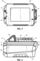
- the battery pack 100 includes a battery housing 102 having an upper battery housing portion 104 coupled to a lower battery housing portion 106 along a seam 108, or interface, via a plurality of threaded fasteners 110 (e.g., screws).
- the upper battery housing portion 104 includes an upper surface 112 and a tool body engagement assembly 114 that extends therefrom.
- the tool body engagement assembly 114 includes a latch assembly housing 116 disposed on the upper battery housing portion 104 adjacent a first end 118 of the upper battery housing portion 104.
- a rail assembly 120 extends along the upper surface 112 of the upper battery housing portion 104 from the latch assembly housing 116 adjacent a second end 122 of the upper battery housing portion 104.
- the rail assembly 120 includes a first rail 124 and a second rail 126 that extend along the length of the rail assembly 120 from a first end 128 of the rail assembly 120 to a second end 130 of the rail assembly 120.
- the rails 124, 126 extend outward from a central portion 132 of the rail assembly 120 away from a central axis 134 of the battery pack 100 such that the rails 124, 126 are parallel to the central axis 134.
- Each rail 124, 126 is generally shaped like an inverted “L” and is sized and shaped to fit into a complementary shaped feature on a battery receptacle of a cordless power tool.
- the tool body engagement assembly 114 further includes a recess 136 that extends into the second end 130 of the rail assembly 120 and terminates at a plurality of terminal openings 138.
- the terminal openings 138 When the battery pack 100 is engaged with a battery receptacle on a cordless power tool, the terminal openings 138 will fit around one or more terminals within the cordless power tool and battery terminals within the terminal openings 138 will be operably coupled to each other to transmit direct current (DC) power from the battery pack 100 to the cordless power tool to provide DC power to a motor and other electrical components within the cordless power tool.
- DC direct current
- the tool body engagement assembly 114 also includes a first latch 140 and a second latch 142 disposed in the latch assembly housing 116 and partially extending into the first end 128 of the rail assembly 120.
- the first latch 140 includes a hook 150 and a release button 152.
- the second latch 142 also includes a hook 154 and a release button 156.
- the first latch 140 and the second latch 142 are biased outward relative to the central axis 134 via one or more springs.
- the hooks 150, 154 engage complementary features of the battery receptable to retain the battery pack 100 in engagement with the cordless tool.
- the release buttons 152, 156 are pressed by a user, the hooks 150, 154 are retracted and the battery pack 100 may be removed from the cordless power tool by sliding the battery pack 100 from the battery receptacle.
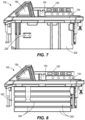
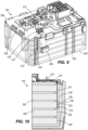
- the battery pack 100 includes a core housing 200 disposed within the battery housing 102. Further, as FIG. 8 shows, a plurality of pouch cells 202 are disposed within the core housing 200. The pouch cells 202 are electrically coupled to each other. Adjacent pouch cells 202 are separated by a plate 204, or spacer. As shown in FIG. 9 , the battery pack 100 further includes a printed circuit board assembly (PCBA) 206 disposed on the top of the core housing 200.
- the PCBA 206 includes a lower PCB 208 and an upper PCB 210 disposed thereon.
- the battery pack 100 includes a flexible circuit 212 having a proximal end 214 and a distal end 216.
- the proximal end 214 of the flexible circuit 212 is electrically and operably coupled to a connector 218 and the flexible circuit 212 extends from the connector 218 down along an inner wall 220 of the core housing 200.
- the flexible circuit 212 also extends along an outer surface 222 of each of the plurality of pouch cells 202.
- FIG. 10 further indicates that the battery pack 100 includes a temperature sensor 224 electrically and operably coupled to a distal end of the flexible circuit 212.
- the temperature sensor 224 is a thermistor.
- the thermistor is a negative temperature coefficient (NTC) thermistor in which the electrical resistance decreases as the temperature increases.
- the thermistor is a positive temperature coefficient (PTC) thermistor in which the electrical resistance increase as the temperature increases.
- a foam backing block 226 extends through an opening 228 in sidewall of the core housing 200 and is aligned with the temperature sensor 224.
- the foam backing block 226 presses against the temperature sensor 224 to keep it aligned and engaged with the outer surface 222 of the pouch cell 202.
- the lower housing portion 106 includes one or more ribs 230 extending inwardly from an inner surface 232 of the lower housing portion 106. The ribs 230 are aligned with the opening 228 in the sidewall of the core housing 200.
- the ribs 230 press against the foam backing block 226 to compress the foam backing block 226 against the temperature sensor 224 to help maintain the temperature 224 in place against the outer surface 222 of the pouch cell 202.
- the temperature sensor 224 allows the temperature of the stack of pouch cells 202 to be accurately. Moreover, the arrangement disclosed herein is relatively easy to assemble in the battery pack 100 and relatively durable.
- the ribs 230 can be sloped, or angled, to facilitate assembly.
- the thermistor 224 and the flexible circuit 212 are within the core housing 200 and do not slide against the lower battery housing portion 106 during assembly.
- a battery pack 300 includes a first pouch cell 302, a second pouch cell 304, a third pouch cell 306, a fourth pouch cell 308, and a fifth pouch cell 310 arranged in a stack.
- a PCBA 312 is disposed above the pouch cells 302, 304, 306, 308, 310.
- a first flexible circuit 320 extends from a first connector 322 down along an exterior surface of the pouch cells 302, 304, 306, 308, 310.
- the first flexible circuit 320 is located outside of a core housing in which the pouch cells 302, 304, 306, 308, 310 are disposed and inside of a lower battery housing portion, i.e., between an outer surface of the core housing and an inner surface of a lower battery housing portion in which the core housing is disposed.
- the first flexible circuit 320 includes a first temperature sensor 324 and a second temperature sensor 326 that are located outside of the core housing and inside of the lower battery housing portion i.e., between an outer surface of the core housing and an inner surface of a lower battery housing portion in which the core housing is disposed.
- the temperature sensors 324, 326 are electrically and operably connected to the first flexible circuit 320.
- the temperature sensors 324, 326 are thermistors, for example.
- the thermistors are negative temperature coefficient (NTC) thermistors in which the electrical resistance decreases as the temperature increases.
- the thermistors are positive temperature coefficient (PTC) thermistors in which the electrical resistance increase as the temperature increases.
- FIG. 11 shows that a first flexible circuit copper trace 328 is electrically and operably coupled to the first temperature sensor 324 and extends from the first temperature sensor 324 into a location within the core housing between the third and fourth pouch cells 306, 308.
- a second flexible circuit copper trace 330 is electrically and operably coupled to the second temperature sensor 326 and extends from the second temperature sensor 326 into a location within the core housing between the first and second pouch cells 302, 304.
- a second flexible circuit 340 extends from a second connector 342 down along an exterior surface of the pouch cells 302, 304, 306, 308, 310.
- the second flexible circuit 340 is located outside of a core housing in which the pouch cells 302, 304, 306, 308, 310 are disposed and inside of a lower battery housing portion, i.e., between an outer surface of the core housing and an inner surface of a lower battery housing portion in which the core housing is disposed.
- the second flexible circuit 320 includes a third temperature sensor 344 and a fourth temperature sensor 346 that are located outside of the core housing and inside of the lower battery housing portion i.e., between an outer surface of the core housing and an inner surface of a lower battery housing portion in which the core housing is disposed.
- the temperature sensors 344, 346 are electrically and operably connected to the second flexible circuit 340.
- the temperature sensors 344, 346 are thermistors, for example.
- the thermistors are negative temperature coefficient (NTC) thermistors in which the electrical resistance decreases as the temperature increases.
- the thermistors are positive temperature coefficient (PTC) thermistors in which the electrical resistance increase as the temperature increases.
- FIG. 11 shows that a third flexible circuit copper trace 348 is electrically and operably coupled to the third temperature sensor 344 and extends from the third temperature sensor 344 into a location within the core housing between the fourth and fifth pouch cells 308, 310.
- a fourth flexible circuit copper trace 350 is electrically and operably coupled to the fourth temperature sensor 346 and extends from the fourth temperature sensor 346 into a location within the core housing between the second and third pouch cells 304, 306.
- the copper traces 328, 330, 348, 350 are able to transmit heat from with the pouch cells 302, 304, 306, 308, 310 to the temperature sensors 324, 326, 344, 346 to provide very accurate temperature data for the stack of pouch cells 302, 304, 306, 308, 310.
- FIG. 12 illustrates another embodiment of a core housing 400 that includes a base plate 410.
- a first sidewall 412 and a second side wall 414 extend perpendicularly from the base plate 410.
- the sidewalls 412, 414 are parallel to each other.
- a rear wall 416 extends perpendicularly from the base plate 410 between the sidewalls 412, 414.
- the rear wall 416 extends along the entire height of the sidewalls 412, 414 and is perpendicular to the sidewalls 412, 414.
- a front wall 418 also extends perpendicularly from the base plate 410 opposite the rear wall 418.
- the front wall 418 is parallel to the rear wall 416.
- the front wall 418 only extends along a portion of the height of the sidewalls 412, 414 such that an opening 420 is formed in the front wall 418 between the sidewalls 412, 414.
- a front endplate 422 is disposed within the opening 420 in the front wall 418.
- the core housing 4002 is formed from a thermally conductive plastic material and may have one or more metal features insert molded therein. These features can include one or more heat sinks, one or more metal fins, or a combination thereof.
- the core housing 402 can be molded with one or more voids, or openings, formed in the based plate 410, the sidewalls 412, 414, or the rear wall 416 to provide ventilation and air flow to carry heat away from one or more pouch cells disposed therein.
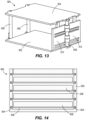
- FIG. 13 illustrates another core housing 500 that includes a lower plate 502 and an upper plate 504 coupled thereto via two rear standoffs 506 and a front standoff 508.
- the standoffs 506, 508 can be cylindrical posts, plates, square posts, or a combination thereof. Further, the standoffs 506, 508 may be made from aluminum.
- one or more doors 510, 512 are mounted on the front standoff 508. This arrangement provides a relatively strong structure for fragile pouch cells. This arrangement also minimizes size and weight.
- the doors 510, 512 swing in and out for assembly. Further, the doors 510, 512 may be plastic to isolate the front standoff 508 from a pair of pouch cell tabs to prevent shorting.
- FIG. 14 illustrates yet another core housing 600 that include an outer housing 602 formed with a plurality of slot pairs 604 arranged horizontally along the same plane.
- a plate 606 with a pouch cell 608 attached thereto is slid into each slot pair 604.
- This arrangement provides for substantial clearance for pouch expansion and minimizes core stack up tolerance for the total height.
- the slot pairs 604 can be arranged vertically.
- FIG. 15 depicts another core housing 700 having an outer housing 702 with a plurality of pouch cells 704 disposed therein.
- the bottom 706 of the housing 702 is a heat sink that is made from aluminum or another material with a high thermal conductivity.
- the core housing 700 could also include one or more thermally conductive inserts along the sides of the pouch cells 704.
Landscapes
- Chemical & Material Sciences (AREA)
- Chemical Kinetics & Catalysis (AREA)
- Electrochemistry (AREA)
- General Chemical & Material Sciences (AREA)
- Engineering & Computer Science (AREA)
- Manufacturing & Machinery (AREA)
- Physics & Mathematics (AREA)
- General Physics & Mathematics (AREA)
- Microelectronics & Electronic Packaging (AREA)
- Life Sciences & Earth Sciences (AREA)
- Biophysics (AREA)
- Nonlinear Science (AREA)
- Computer Hardware Design (AREA)
- Battery Mounting, Suspending (AREA)
- Secondary Cells (AREA)
Applications Claiming Priority (1)
| Application Number | Priority Date | Filing Date | Title |
|---|---|---|---|
| US202263430585P | 2022-12-06 | 2022-12-06 |
Publications (2)
| Publication Number | Publication Date |
|---|---|
| EP4383404A2 true EP4383404A2 (de) | 2024-06-12 |
| EP4383404A3 EP4383404A3 (de) | 2024-08-14 |
Family
ID=89076205
Family Applications (1)
| Application Number | Title | Priority Date | Filing Date |
|---|---|---|---|
| EP23213913.9A Pending EP4383404A3 (de) | 2022-12-06 | 2023-12-04 | Batteriepack |
Country Status (4)
| Country | Link |
|---|---|
| US (1) | US20240186601A1 (de) |
| EP (1) | EP4383404A3 (de) |
| JP (2) | JP7723062B2 (de) |
| CN (1) | CN222126843U (de) |
Families Citing this family (1)
| Publication number | Priority date | Publication date | Assignee | Title |
|---|---|---|---|---|
| USD1089065S1 (en) * | 2023-09-05 | 2025-08-19 | Thiss Technology Co., Ltd. | Battery pack |
Family Cites Families (10)
| Publication number | Priority date | Publication date | Assignee | Title |
|---|---|---|---|---|
| WO2014206323A1 (en) | 2013-06-26 | 2014-12-31 | Techtronic Power Tools Technology Limited | Battery pack,tool battery and battery operated tool |
| EP3161899A4 (de) | 2014-06-30 | 2017-12-27 | Black & Decker Inc. | Batteriepack für schnurlose elektrowerkzeuge |
| CN110114904B (zh) | 2016-12-27 | 2022-07-15 | 裕罗有限公司 | 汇流排组件及支架组件 |
| EP3525279A1 (de) * | 2018-02-09 | 2019-08-14 | Nederlandse Organisatie voor toegepast- natuurwetenschappelijk onderzoek TNO | Thermistore auf flexibler schichten und derer verwendung zur temperaturmessung im batteriepack |
| KR102522165B1 (ko) | 2018-12-26 | 2023-04-13 | 주식회사 엘지에너지솔루션 | 정확한 온도 센싱이 가능한 구조를 갖는 배터리 모듈, 이러한 배터리 모듈을 포함하는 배터리 팩 및 자동차 |
| EP3736873A1 (de) | 2019-05-10 | 2020-11-11 | Andreas Stihl AG & Co. KG | Akkupack, bearbeitungssystem und verfahren zur herstellung eines akkupacks |
| DE102020206446A1 (de) | 2020-05-25 | 2021-11-25 | Robert Bosch Gesellschaft mit beschränkter Haftung | Akkupack |
| KR102866740B1 (ko) | 2020-08-11 | 2025-09-29 | 주식회사 엘지에너지솔루션 | 조립성이 개선된 배터리 모듈 및 이를 포함하는 배터리 팩 |
| JP7593768B2 (ja) * | 2020-10-06 | 2024-12-03 | トヨタ自動車株式会社 | 電池パック |
| US20230378621A1 (en) * | 2022-05-17 | 2023-11-23 | Milwaukee Electric Tool Corporation | Battery pack |
-
2023
- 2023-11-28 US US18/521,207 patent/US20240186601A1/en active Pending
- 2023-12-01 JP JP2023203851A patent/JP7723062B2/ja active Active
- 2023-12-04 EP EP23213913.9A patent/EP4383404A3/de active Pending
- 2023-12-06 CN CN202323324812.5U patent/CN222126843U/zh active Active
-
2025
- 2025-07-31 JP JP2025128093A patent/JP2025186219A/ja active Pending
Also Published As
| Publication number | Publication date |
|---|---|
| EP4383404A3 (de) | 2024-08-14 |
| JP2024081612A (ja) | 2024-06-18 |
| US20240186601A1 (en) | 2024-06-06 |
| JP2025186219A (ja) | 2025-12-23 |
| JP7723062B2 (ja) | 2025-08-13 |
| CN222126843U (zh) | 2024-12-06 |
Similar Documents
| Publication | Publication Date | Title |
|---|---|---|
| EP1780825B1 (de) | Akkupack und Innenbauelementanordnung für ein schnurloses elektrisches Werkzeugsystem | |
| CN100423322C (zh) | 电池组 | |
| EP4383404A2 (de) | Batteriepack | |
| CN105101744A (zh) | 具有集成电气部件的用于冷却其的冷却板 | |
| EP2132805B1 (de) | Stromspeichervorrichtung | |
| CN201156565Y (zh) | 电池充电单元 | |
| CN201032639Y (zh) | 用于无塞绳电动工具的电池组 | |
| CN213782135U (zh) | 一种电池模组、电池包以及用电设备 | |
| US20150086829A1 (en) | Battery module having thermally conductive holding frame | |
| CN217388260U (zh) | 一种便于散热的充电器 | |
| CN118888958A (zh) | 储能电源 | |
| CN215378803U (zh) | 一种光伏储能柜 | |
| CN207353352U (zh) | 一种用于电动工具的电池包 | |
| CN217507480U (zh) | 加热片 | |
| CN216120642U (zh) | 一种模块极耳支架及包含其的软包电池模组 | |
| CN222214558U (zh) | 一种散热风机的接电机构 | |
| CN223583266U (zh) | 一种电子元器件触头的电连接结构及控制设备 | |
| CN222463322U (zh) | 支架、电池组、电池装置及用电设备 | |
| CN218975907U (zh) | 一种稳定的电源适配器 | |
| CN223651567U (zh) | 电池模组和储能系统 | |
| CN213547147U (zh) | 一种带有免插入结构的电池盒 | |
| CN214100002U (zh) | 一种带有防脱落连接扣的插座 | |
| CN220569722U (zh) | 一种二次电池及电池模组 | |
| CN214100140U (zh) | 一种便于安装的插座底座 | |
| CN222562856U (zh) | 一种便捷式电池组壳体 |
Legal Events
| Date | Code | Title | Description |
|---|---|---|---|
| PUAI | Public reference made under article 153(3) epc to a published international application that has entered the european phase |
Free format text: ORIGINAL CODE: 0009012 |
|
| STAA | Information on the status of an ep patent application or granted ep patent |
Free format text: STATUS: REQUEST FOR EXAMINATION WAS MADE |
|
| 17P | Request for examination filed |
Effective date: 20231204 |
|
| AK | Designated contracting states |
Kind code of ref document: A2 Designated state(s): AL AT BE BG CH CY CZ DE DK EE ES FI FR GB GR HR HU IE IS IT LI LT LU LV MC ME MK MT NL NO PL PT RO RS SE SI SK SM TR |
|
| PUAL | Search report despatched |
Free format text: ORIGINAL CODE: 0009013 |
|
| RIC1 | Information provided on ipc code assigned before grant |
Ipc: H01M 50/569 20210101ALI20240704BHEP Ipc: H01M 50/247 20210101ALI20240704BHEP Ipc: H01M 50/211 20210101ALI20240704BHEP Ipc: H01M 10/6235 20140101ALI20240704BHEP Ipc: H01M 10/42 20060101ALI20240704BHEP Ipc: H01M 10/48 20060101AFI20240704BHEP |
|
| AK | Designated contracting states |
Kind code of ref document: A3 Designated state(s): AL AT BE BG CH CY CZ DE DK EE ES FI FR GB GR HR HU IE IS IT LI LT LU LV MC ME MK MT NL NO PL PT RO RS SE SI SK SM TR |