EP4383370A1 - High-nickel low-cobalt positive electrode material, preparation method therefor and use thereof - Google Patents
High-nickel low-cobalt positive electrode material, preparation method therefor and use thereof Download PDFInfo
- Publication number
- EP4383370A1 EP4383370A1 EP23793221.5A EP23793221A EP4383370A1 EP 4383370 A1 EP4383370 A1 EP 4383370A1 EP 23793221 A EP23793221 A EP 23793221A EP 4383370 A1 EP4383370 A1 EP 4383370A1
- Authority
- EP
- European Patent Office
- Prior art keywords
- cathode material
- coating layer
- cobalt
- material matrix
- nickel low
- Prior art date
- Legal status (The legal status is an assumption and is not a legal conclusion. Google has not performed a legal analysis and makes no representation as to the accuracy of the status listed.)
- Pending
Links
Images

Classifications
-
- H—ELECTRICITY
- H01—ELECTRIC ELEMENTS
- H01M—PROCESSES OR MEANS, e.g. BATTERIES, FOR THE DIRECT CONVERSION OF CHEMICAL ENERGY INTO ELECTRICAL ENERGY
- H01M4/00—Electrodes
- H01M4/02—Electrodes composed of, or comprising, active material
- H01M4/36—Selection of substances as active materials, active masses, active liquids
-
- C—CHEMISTRY; METALLURGY
- C01—INORGANIC CHEMISTRY
- C01G—COMPOUNDS CONTAINING METALS NOT COVERED BY SUBCLASSES C01D OR C01F
- C01G53/00—Compounds of nickel
- C01G53/40—Complex oxides containing nickel and at least one other metal element
- C01G53/42—Complex oxides containing nickel and at least one other metal element containing alkali metals, e.g. LiNiO2
-
- H—ELECTRICITY
- H01—ELECTRIC ELEMENTS
- H01M—PROCESSES OR MEANS, e.g. BATTERIES, FOR THE DIRECT CONVERSION OF CHEMICAL ENERGY INTO ELECTRICAL ENERGY
- H01M10/00—Secondary cells; Manufacture thereof
- H01M10/05—Accumulators with non-aqueous electrolyte
- H01M10/052—Li-accumulators
-
- H—ELECTRICITY
- H01—ELECTRIC ELEMENTS
- H01M—PROCESSES OR MEANS, e.g. BATTERIES, FOR THE DIRECT CONVERSION OF CHEMICAL ENERGY INTO ELECTRICAL ENERGY
- H01M10/00—Secondary cells; Manufacture thereof
- H01M10/05—Accumulators with non-aqueous electrolyte
- H01M10/052—Li-accumulators
- H01M10/0525—Rocking-chair batteries, i.e. batteries with lithium insertion or intercalation in both electrodes; Lithium-ion batteries
-
- H—ELECTRICITY
- H01—ELECTRIC ELEMENTS
- H01M—PROCESSES OR MEANS, e.g. BATTERIES, FOR THE DIRECT CONVERSION OF CHEMICAL ENERGY INTO ELECTRICAL ENERGY
- H01M4/00—Electrodes
- H01M4/02—Electrodes composed of, or comprising, active material
- H01M4/13—Electrodes for accumulators with non-aqueous electrolyte, e.g. for lithium-accumulators; Processes of manufacture thereof
- H01M4/131—Electrodes based on mixed oxides or hydroxides, or on mixtures of oxides or hydroxides, e.g. LiCoOx
-
- H—ELECTRICITY
- H01—ELECTRIC ELEMENTS
- H01M—PROCESSES OR MEANS, e.g. BATTERIES, FOR THE DIRECT CONVERSION OF CHEMICAL ENERGY INTO ELECTRICAL ENERGY
- H01M4/00—Electrodes
- H01M4/02—Electrodes composed of, or comprising, active material
- H01M4/13—Electrodes for accumulators with non-aqueous electrolyte, e.g. for lithium-accumulators; Processes of manufacture thereof
- H01M4/139—Processes of manufacture
- H01M4/1391—Processes of manufacture of electrodes based on mixed oxides or hydroxides, or on mixtures of oxides or hydroxides, e.g. LiCoOx
-
- H—ELECTRICITY
- H01—ELECTRIC ELEMENTS
- H01M—PROCESSES OR MEANS, e.g. BATTERIES, FOR THE DIRECT CONVERSION OF CHEMICAL ENERGY INTO ELECTRICAL ENERGY
- H01M4/00—Electrodes
- H01M4/02—Electrodes composed of, or comprising, active material
- H01M4/36—Selection of substances as active materials, active masses, active liquids
- H01M4/362—Composites
- H01M4/366—Composites as layered products
-
- H—ELECTRICITY
- H01—ELECTRIC ELEMENTS
- H01M—PROCESSES OR MEANS, e.g. BATTERIES, FOR THE DIRECT CONVERSION OF CHEMICAL ENERGY INTO ELECTRICAL ENERGY
- H01M4/00—Electrodes
- H01M4/02—Electrodes composed of, or comprising, active material
- H01M4/36—Selection of substances as active materials, active masses, active liquids
- H01M4/48—Selection of substances as active materials, active masses, active liquids of inorganic oxides or hydroxides
- H01M4/485—Selection of substances as active materials, active masses, active liquids of inorganic oxides or hydroxides of mixed oxides or hydroxides for inserting or intercalating light metals, e.g. LiTi2O4 or LiTi2OxFy
-
- H—ELECTRICITY
- H01—ELECTRIC ELEMENTS
- H01M—PROCESSES OR MEANS, e.g. BATTERIES, FOR THE DIRECT CONVERSION OF CHEMICAL ENERGY INTO ELECTRICAL ENERGY
- H01M4/00—Electrodes
- H01M4/02—Electrodes composed of, or comprising, active material
- H01M4/36—Selection of substances as active materials, active masses, active liquids
- H01M4/48—Selection of substances as active materials, active masses, active liquids of inorganic oxides or hydroxides
- H01M4/50—Selection of substances as active materials, active masses, active liquids of inorganic oxides or hydroxides of manganese
- H01M4/505—Selection of substances as active materials, active masses, active liquids of inorganic oxides or hydroxides of manganese of mixed oxides or hydroxides containing manganese for inserting or intercalating light metals, e.g. LiMn2O4 or LiMn2OxFy
-
- H—ELECTRICITY
- H01—ELECTRIC ELEMENTS
- H01M—PROCESSES OR MEANS, e.g. BATTERIES, FOR THE DIRECT CONVERSION OF CHEMICAL ENERGY INTO ELECTRICAL ENERGY
- H01M4/00—Electrodes
- H01M4/02—Electrodes composed of, or comprising, active material
- H01M4/36—Selection of substances as active materials, active masses, active liquids
- H01M4/48—Selection of substances as active materials, active masses, active liquids of inorganic oxides or hydroxides
- H01M4/52—Selection of substances as active materials, active masses, active liquids of inorganic oxides or hydroxides of nickel, cobalt or iron
- H01M4/525—Selection of substances as active materials, active masses, active liquids of inorganic oxides or hydroxides of nickel, cobalt or iron of mixed oxides or hydroxides containing iron, cobalt or nickel for inserting or intercalating light metals, e.g. LiNiO2, LiCoO2 or LiCoOxFy
-
- H—ELECTRICITY
- H01—ELECTRIC ELEMENTS
- H01M—PROCESSES OR MEANS, e.g. BATTERIES, FOR THE DIRECT CONVERSION OF CHEMICAL ENERGY INTO ELECTRICAL ENERGY
- H01M4/00—Electrodes
- H01M4/02—Electrodes composed of, or comprising, active material
- H01M4/36—Selection of substances as active materials, active masses, active liquids
- H01M4/58—Selection of substances as active materials, active masses, active liquids of inorganic compounds other than oxides or hydroxides, e.g. sulfides, selenides, tellurides, halogenides or LiCoFy; of polyanionic structures, e.g. phosphates, silicates or borates
-
- H—ELECTRICITY
- H01—ELECTRIC ELEMENTS
- H01M—PROCESSES OR MEANS, e.g. BATTERIES, FOR THE DIRECT CONVERSION OF CHEMICAL ENERGY INTO ELECTRICAL ENERGY
- H01M4/00—Electrodes
- H01M4/02—Electrodes composed of, or comprising, active material
- H01M4/62—Selection of inactive substances as ingredients for active masses, e.g. binders, fillers
-
- C—CHEMISTRY; METALLURGY
- C01—INORGANIC CHEMISTRY
- C01P—INDEXING SCHEME RELATING TO STRUCTURAL AND PHYSICAL ASPECTS OF SOLID INORGANIC COMPOUNDS
- C01P2002/00—Crystal-structural characteristics
- C01P2002/50—Solid solutions
- C01P2002/52—Solid solutions containing elements as dopants
-
- C—CHEMISTRY; METALLURGY
- C01—INORGANIC CHEMISTRY
- C01P—INDEXING SCHEME RELATING TO STRUCTURAL AND PHYSICAL ASPECTS OF SOLID INORGANIC COMPOUNDS
- C01P2002/00—Crystal-structural characteristics
- C01P2002/70—Crystal-structural characteristics defined by measured X-ray, neutron or electron diffraction data
- C01P2002/72—Crystal-structural characteristics defined by measured X-ray, neutron or electron diffraction data by d-values or two theta-values, e.g. as X-ray diagram
-
- C—CHEMISTRY; METALLURGY
- C01—INORGANIC CHEMISTRY
- C01P—INDEXING SCHEME RELATING TO STRUCTURAL AND PHYSICAL ASPECTS OF SOLID INORGANIC COMPOUNDS
- C01P2004/00—Particle morphology
- C01P2004/01—Particle morphology depicted by an image
- C01P2004/03—Particle morphology depicted by an image obtained by SEM
-
- C—CHEMISTRY; METALLURGY
- C01—INORGANIC CHEMISTRY
- C01P—INDEXING SCHEME RELATING TO STRUCTURAL AND PHYSICAL ASPECTS OF SOLID INORGANIC COMPOUNDS
- C01P2004/00—Particle morphology
- C01P2004/01—Particle morphology depicted by an image
- C01P2004/04—Particle morphology depicted by an image obtained by TEM, STEM, STM or AFM
-
- C—CHEMISTRY; METALLURGY
- C01—INORGANIC CHEMISTRY
- C01P—INDEXING SCHEME RELATING TO STRUCTURAL AND PHYSICAL ASPECTS OF SOLID INORGANIC COMPOUNDS
- C01P2004/00—Particle morphology
- C01P2004/51—Particles with a specific particle size distribution
-
- C—CHEMISTRY; METALLURGY
- C01—INORGANIC CHEMISTRY
- C01P—INDEXING SCHEME RELATING TO STRUCTURAL AND PHYSICAL ASPECTS OF SOLID INORGANIC COMPOUNDS
- C01P2004/00—Particle morphology
- C01P2004/60—Particles characterised by their size
- C01P2004/61—Micrometer sized, i.e. from 1-100 micrometer
-
- C—CHEMISTRY; METALLURGY
- C01—INORGANIC CHEMISTRY
- C01P—INDEXING SCHEME RELATING TO STRUCTURAL AND PHYSICAL ASPECTS OF SOLID INORGANIC COMPOUNDS
- C01P2004/00—Particle morphology
- C01P2004/80—Particles consisting of a mixture of two or more inorganic phases
-
- C—CHEMISTRY; METALLURGY
- C01—INORGANIC CHEMISTRY
- C01P—INDEXING SCHEME RELATING TO STRUCTURAL AND PHYSICAL ASPECTS OF SOLID INORGANIC COMPOUNDS
- C01P2004/00—Particle morphology
- C01P2004/80—Particles consisting of a mixture of two or more inorganic phases
- C01P2004/82—Particles consisting of a mixture of two or more inorganic phases two phases having the same anion, e.g. both oxidic phases
- C01P2004/84—Particles consisting of a mixture of two or more inorganic phases two phases having the same anion, e.g. both oxidic phases one phase coated with the other
-
- C—CHEMISTRY; METALLURGY
- C01—INORGANIC CHEMISTRY
- C01P—INDEXING SCHEME RELATING TO STRUCTURAL AND PHYSICAL ASPECTS OF SOLID INORGANIC COMPOUNDS
- C01P2006/00—Physical properties of inorganic compounds
- C01P2006/40—Electric properties
-
- C—CHEMISTRY; METALLURGY
- C01—INORGANIC CHEMISTRY
- C01P—INDEXING SCHEME RELATING TO STRUCTURAL AND PHYSICAL ASPECTS OF SOLID INORGANIC COMPOUNDS
- C01P2006/00—Physical properties of inorganic compounds
- C01P2006/80—Compositional purity
-
- H—ELECTRICITY
- H01—ELECTRIC ELEMENTS
- H01M—PROCESSES OR MEANS, e.g. BATTERIES, FOR THE DIRECT CONVERSION OF CHEMICAL ENERGY INTO ELECTRICAL ENERGY
- H01M4/00—Electrodes
- H01M4/02—Electrodes composed of, or comprising, active material
- H01M2004/026—Electrodes composed of, or comprising, active material characterised by the polarity
- H01M2004/028—Positive electrodes
-
- Y—GENERAL TAGGING OF NEW TECHNOLOGICAL DEVELOPMENTS; GENERAL TAGGING OF CROSS-SECTIONAL TECHNOLOGIES SPANNING OVER SEVERAL SECTIONS OF THE IPC; TECHNICAL SUBJECTS COVERED BY FORMER USPC CROSS-REFERENCE ART COLLECTIONS [XRACs] AND DIGESTS
- Y02—TECHNOLOGIES OR APPLICATIONS FOR MITIGATION OR ADAPTATION AGAINST CLIMATE CHANGE
- Y02E—REDUCTION OF GREENHOUSE GAS [GHG] EMISSIONS, RELATED TO ENERGY GENERATION, TRANSMISSION OR DISTRIBUTION
- Y02E60/00—Enabling technologies; Technologies with a potential or indirect contribution to GHG emissions mitigation
- Y02E60/10—Energy storage using batteries
Definitions
- the present disclosure relates to the technical field of lithium ion batteries, and particularly to a high-nickel low-cobalt cathode material and a preparation method and use thereof.
- An embodiment of the present disclosure provides a high-nickel low-cobalt cathode material, including a cathode material matrix, a first coating layer, and a second coating layer, wherein the first coating layer is coated on a surface of the cathode material matrix, and the second coating layer is coated on a surface of the first coating layer;
- the cathode material matrix includes a material of a chemical formula LiNi x Co y M 1-x-y O 2 , where M includes one or more of Mn and Al, 0.88 ⁇ x ⁇ 0.98, 0 ⁇ y ⁇ 0.06, and x+y ⁇ 1.
- a total mass of the first coating layer and the second coating layer a mass of the cathode material matrix is (0.0001 to 0.005): 1.
- the first coating layer has a thickness of 5 nm to 10 nm.
- the first coating layer is of spinel phase.
- the second coating layer has a thickness of 2 nm to 5 nm.
- the second coating layer is of halite phase.
- the present disclosure further provides a preparation method of the above high-nickel low-cobalt cathode material, including following steps:
- phosphorous element in the sulfur phosphorus compound the cathode material matrix is (0.001 to 0.01): 1 in molar ratio.
- the sulfur phosphorus compound comprises one or more of phosphorus sulfide and phosphorus trisulfide.
- process conditions of the first calcination treatment include: a first calcination temperature of 260 °C to 600 °C, and first calcination time of 4 h to 12 h.
- the preparation method of the cathode material matrix includes following steps:
- the cathode material matrix precursor includes a material of a chemical formula Ni x Co y M 1-x-y (OH) 2 , where M includes one or more of Mn and Al, 0.88 ⁇ x ⁇ 0.98, 0 ⁇ y ⁇ 0.06, and x+y ⁇ 1.
- the lithium source includes one or more of lithium hydroxide and lithium carbonate.
- the metal compound includes a compound of one or more of Mg, Ti, Zr, Y, Nb, W, Ce, Sb, Sr, and Ta.
- a temperature of the second calcination treatment is 600 °C to 1000 °C, and time of the second calcination treatment is 4 h to 20 h.
- lithium ion in the lithium source: metal element in the metal compound: the cathode material matrix precursor is (1.00 to 1.08): (0 to 0.02): 1 in step S1.
- the present disclosure further provides a cathode sheet, including the above high-nickel low-cobalt cathode material or the high-nickel low-cobalt cathode material prepared by the above preparation method.
- the present disclosure further provides a lithium ion battery, including the above cathode sheet.
- the present disclosure further provides a power consumption device, including the above lithium ion battery.
- the high-nickel low-cobalt cathode material and the preparation method and use thereof at least have the following advantages:
- An embodiment of the present disclosure provides a high-nickel low-cobalt cathode material, including a cathode material matrix, a first coating layer, and a second coating layer, wherein the first coating layer is coated on a surface of the cathode material matrix, and the second coating layer is coated on a surface of the first coating layer.
- the first coating layer includes a material of a chemical formula Li a Ni b Co c M 1-b-c O d , where M includes one or two of Mn and Al, 0.2 ⁇ a ⁇ 1, 0.88 ⁇ b ⁇ 0.98, 0 ⁇ c ⁇ 0.06, b+c ⁇ 1, and 1.6 ⁇ d ⁇ 2.
- a material of the second coating layer includes one or more of Li 3 PO 4 , Li 2 SO 4 , and LiPOs.
- the above first coating layer can effectively isolate the cathode material matrix from an external environment.
- Li 3 PO 4 , Li 2 SO 4 , and LiPO 3 of the second coating layer can prevent electrochemical decomposition behaviors of (010) active crystal plane of the high-nickel low-cobalt cathode material during charging and discharging, thus achieving effective protection to the active crystal face.
- the first coating layer and the second coating layer can prevent decomposition of an electrolytic solution and corrosion of the electrolytic solution to the cathode material matrix, protect the integrity of layered structure of bulk phase of the high-nickel low-cobalt cathode material, and effectively prevent decomposition of the bulk phase structure, further improving discharging specific capacity, initial efficiency, and cycle life of the lithium ion battery.
- the cathode material matrix includes a material of a chemical formula LiNi x Co y M 1-x-y O 2 , where M includes one or more of Mn and Al, 0.88 ⁇ x ⁇ 0.98, 0 ⁇ y ⁇ 0.06, and x+y ⁇ 1.
- x may be, for example, 0.89, 0.90, 0.91, 0.92, 0.93, 0.94, 0.95, 0.96, 0.97, 0.98
- y may be, for example, 0.01, 0.02, 0.03, 0.04 or 0.05.
- a total mass of the first coating layer and the second coating layer: a mass of the cathode material matrix is (0.0001 to 0.005): 1. It can be understood that the ratio of the total mass of the first coating layer and the second coating layer to the mass of the cathode material matrix may be, for example, 0.0001:1, 0.00012:1, 0.00013:1, 0.00015:1, 0.00018:1, 0.0002:1, 0.00022:1, 0.00025:1, 0.00028:1, 0.0003:1, 0.00035:1, 0.0004:1, 0.00045:1 or 0.0005:1.
- the first coating layer has a thickness of 5 nm to 10 nm. It can understood that the thickness of the first coating layer may be, for example, 5 nm, 5.5 nm, 6 nm, 6.5 nm, 7 nm, 7.5 nm, 8 nm, 8.5 nm, 9 nm, 9.5 nm, or 10 nm, and the thickness of the first coating layer also may be other values from 5 nm to 10 nm.
- the first coating layer is of spinel phase. It should be noted that a fast ionic conductor coating layer is formed on the surface of the first coating layer having the spinel phase, which can prevent the electrochemical decomposition behaviors of the (010) active crystal plane of the high-nickel low-cobalt cathode material during charging and discharging, thereby achieving effective protection to the active crystal face.
- the second coating layer is of halite phase.
- the above first coating layer and second coating layer being of the spinel phase and the halite phase greatly improves the stability of the surface structure of the high-nickel low-cobalt cathode material, thereby improving the electrochemical performance.
- the second coating layer has a thickness of 2 nm to 5 nm. It can be understood that the thickness of the second coating layer may be, for example, 2 nm, 2.5 nm, 3 nm, 3.5 nm, 4 nm, 4.5 nm, or 5 nm, and the thickness of the second coating layer also may be other values from 2 nm to 5 nm.
- Another embodiment of the present disclosure provides a preparation method of the above high-nickel low-cobalt cathode material, including the following steps:
- the above cathode material matrix includes a material of a chemical formula LiNi x Co y M 1-x-y O 2 , where M includes one or more of Mn and Al, 0.88 ⁇ x ⁇ 0.98, 0 ⁇ y ⁇ 0.06, and x+y ⁇ 1.
- the above cathode material reacts with the sulfur phosphorus compound when being subjected to the first calcination treatment, thereby forming the first coating layer and the second coating layer.
- the formed first coating layer includes a material of a chemical formula Li a Ni b Co c M 1-b-c O d , where M includes one or both of Mn and Al, where 0.2 ⁇ a ⁇ 1, 0.88 ⁇ b ⁇ 0.98, 0 ⁇ c ⁇ 0.06, b+c ⁇ 1, and 1.6 ⁇ d ⁇ 2.
- a material of the second coating layer includes one or more of Li 3 PO 4 , Li 2 SO 4 , and LiPOs.
- the coating of the cathode material matrix can be completed through the first calcination treatment, thereby reducing the conventional water washing and drying processes, reducing production costs, facilitating industrial production, and meanwhile solving the problems that the conventional high-nickel cathode material has high residual alkali, and lithium-ion transmission channels are blocked to hinder exertion of performance.
- the above sulfur phosphorus compound reconstructs the layered phase of the surface of the cathode material matrix into a more stable spinel phase through strong lithium deintercalation and deoxygenation under thermodynamic equilibrium, and meanwhile, multiple types of amorphous fast ionic conductor coating layers are formed on an outer surface of the first coating layer, which can prevent the electrochemical decomposition behaviors of the (010) active crystal plane of the material during charging and discharging, and achieve the effective protection to the active crystal face.
- the above first coating layer and second coating layer can prevent decomposition of an electrolytic solution and corrosion of the electrolytic solution to the cathode material matrix, protect the integrity of layered structure of bulk phase of the high-nickel low-cobalt cathode material, and effectively prevent decomposition of the bulk phase structure, further improving discharging specific capacity, initial efficiency, and cycle life of the battery.
- phosphorous element in the sulfur phosphorus compound: the cathode material matrix is (0.001 to 0.01): 1 in molar ratio. It can be understood that the molar ratio of the phosphorous element in the sulfur phosphorus compound to the cathode material matrix may be, for example, 0.001:1, 0.002:1, 0.003:1, 0.004:1, 0.005:1, 0.006:1, 0.007:1, 0.008:1, 0.009:1 or 0.01:1.
- the sulfur phosphorus compound includes one or more of phosphorus sulfide and phosphorus pentasulfide.
- process conditions of the first calcination treatment include: a first calcination temperature of 260 °C to 600 °C, and first calcination time of 4 h to 12 h.
- the first calcination temperature may be any value from 260 °C to 600 °C, for example: 260 °C, 280 °C, 300 °C, 320 °C, 340 °C, 360 °C, 380 °C, 400 °C, 450 °C, 500 °C, 550 °C, 600 °C
- the first calcination time may be any value from 4 h to 12 h, and may be, for example, 4 h, 5 h, 6 h, 7 h, 8 h, 9 h, 10 h.
- the preparation method of a cathode material matrix includes the following steps:
- a median particle size D50 thereof is 1.2 ⁇ m to 15 ⁇ m. It can be understood that the median particle size D50 of the above cathode material matrix obtained after the sieving treatment may be, for example, 1.2 ⁇ m, 1.5 ⁇ m, 2 ⁇ m, 3 ⁇ m, 4 ⁇ m, 5 ⁇ m, 6 ⁇ m, 7 ⁇ m, 8 ⁇ m, 9 ⁇ m, 10 ⁇ m, 11 ⁇ m, 12 ⁇ m, 13 ⁇ m, 14 ⁇ m or 15 ⁇ m.
- the cathode material matrix precursor includes a material of a chemical formula Ni x Co y M 1-x-y (OH) 2 , where M includes one or more of Mn and Al, 0.88 ⁇ x ⁇ 0.98, 0 ⁇ y ⁇ 0.06, and x+y ⁇ 1.
- x may be, for example, 0.89, 0.90, 0.91, 0.92, 0.93, 0.94, 0.95, 0.96, 0.97 or 0.98
- y may be, for example, 0.01, 0.02, 0.03, 0.04 or 0.05.
- the lithium source includes one or more of lithium hydroxide and lithium carbonate.
- the metal compound includes a compound of one or more of Mg, Ti, Zr, Y, Nb, W, Ce, Sb, Sr, and Ta.
- the metal compound may be oxide, hydroxide or carbonate of the above metals, for example, MgO, TiO 2 , ZrO 2 , Y 2 O 3 , Nb 2 O 5 , WO 3 , CeO 2 , Sb 2 O 3 , Sb 2 O 5 , SrO, Ta 2 O 5 , Mg(OH) 2 , Zr(OH) 4 , Ti(OH) 4 , Sr(OH) 2 , MgCO 3 , SrCO 3 or Zr 3 (CO 3 )O 5 .
- a temperature of the second calcination treatment is 600 °C to 1000 °C
- time of the second calcination treatment is 4 h to 20 h.
- the temperature of the second calcination treatment may be any value from 600 °C to 1000 °C, for example, it may be 600 °C, 650 °C, 700 °C, 750 °C, 800 °C, 850 °C, 900 °C, 950 °C or 1000 °C
- the time of the second calcination treatment may be 4 h, 5 h, 6 h, 7 h, 8 h, 9 h, 10 h, 11 h, 12 h, 13 h, 14 h, 15 h, 16 h, 17 h, 18 h, 19 h or 20 h, and also may be other values from 4 h to 20 h.
- lithium ion in the lithium source: metal element in the metal compound: the cathode material matrix precursor is (1.00 to 1.08): (0 to 0.02): 1 in step S1. It can be understood that in molar ratio, the lithium ion in the lithium source: the metal element in the metal compound: the cathode material matrix precursor in step S1 may be 1.00:0.01:1, 1.01:0.012:1, 1.02:0.013:1, 1.03:0.014:1, 1.04:0.015:1, 1.05:0.016:1, 1.06:0.017:1, 1.07:0.018:1, 1.08:0.019:1 or 1.08:0.02:1, etc.
- Another embodiment of the present disclosure provides a cathode sheet, including the above high-nickel low-cobalt cathode material or the high-nickel low-cobalt cathode material prepared by the above preparation method.
- the above cathode sheet includes a cathode current collector and a cathode active substance layer disposed on at least one surface of the cathode current collector.
- the cathode active substance layer includes a cathode active substance, a conductive agent, and a binder.
- the cathode active substance can use the above high-nickel low-cobalt cathode material or the high-nickel low-cobalt cathode material prepared by the above preparation method.
- the conductive agent and the binder are not particularly limited, and the conductive agents and the binders commonly used in the art can be used.
- the conductive agent may be a material such as carbon black, acetylene black, ketjen black, carbon fiber, carbon nanotube, and graphene, or a mixture thereof
- the binder includes, but is not limited to, vinylidene fluoride, polyvinyl alcohol, carboxymethyl cellulose, hydroxypropyl cellulose, hydroxyethyl cellulose, polytetrafluoroethylene, etc.
- a preparation process of the above cathode sheet includes, but is not limited to, coating a slurry obtained by mixing the cathode active substance, the conductive agent, the binder, and a solvent on the cathode current collector, and performing steps such as a drying process, a rolling process, and a slicing process in turn to obtain the cathode sheet.
- Another embodiment of the present disclosure provides a lithium ion battery, including the above cathode sheet.
- a preparation method of the above lithium ion battery includes, but is not limited to: laminating or winding the above cathode sheet, a separator, and a negative electrode sheet to obtain an electrode set, and assembling the electrode set with a case and then injecting an electrolytic solution into the case to obtain the lithium ion battery.
- a PE film or a PP film can be selected as the separator, and graphite, soft carbon, hard carbon, composite carbon, silicon material or metallic lithium, etc. can be selected as the negative electrode material.
- Another embodiment of the present disclosure provides a power consumption device, including the above lithium ion battery.
- the above power consumption device includes, but is not limited to, a bicycle, a calculator, a portable audio recorder, a radio, a backup power supply, a lighting equipment, a toy, an electric tool, a notebook computer, a mobile computer, a game machine, a liquid crystal television, a motorcycle, a motor, an automobile, a camera, and the like.
- a lithium source was LiOH
- a metal compound was ZrO 2
- a high-nickel low-cobalt cathode material matrix precursor was Ni 0.95 Co 0.03 Mn 0.02 (OH) 2 .
- a preparation method of a high-nickel low-cobalt cathode material included the following steps:
- a lithium source was LiOH
- a metal compound was TiO 2
- a high-nickel low-cobalt cathode material matrix precursor was Ni 0.94 Co 0.03 Al 0.03 (OH) 2 .
- a preparation method of a high-nickel low-cobalt cathode material included the following steps:
- a lithium source was LiOH
- a metal compound was SrCO 3
- a high-nickel low-cobalt cathode material matrix precursor was Ni 0.96 Co 0.02 Mn 0.02 (OH) 2 .
- a preparation method of a high-nickel low-cobalt cathode material included the following steps:
- a lithium source was LiOH
- metal compounds were ZrO 2 and SrCOs
- a high-nickel low-cobalt cathode material matrix precursor was Ni 0.95 Co 0.02 Mn 0.02 Al 0.01 (OH) 2 .
- a preparation method of a high-nickel low-cobalt cathode material included the following steps:
- the difference lies in that, in step S3, the high-nickel low-cobalt cathode material matrix and the phosphorus sulfide were fully mixed according to a molar ratio of the high-nickel low-cobalt cathode material matrix to phosphorus element in the phosphorus sulfide being 1 :0.001.
- the material of the first coating layer included LiNi 0.95 Co 0.03 Mn 0.02 O 2
- a material of the second coating layer included Li 3 PO 4 , Li 2 SO 4 , and LiPOs.
- the difference lies in that the high-nickel low-cobalt cathode material matrix and the phosphorus sulfide were fully mixed according to a molar ratio of the high-nickel low-cobalt cathode material matrix to phosphorus element in the phosphorus sulfide being 1:0.01.
- the material of the first coating layer included LiNi 0.95 Co 0.03 Mn 0.02 O 2
- a material of the second coating layer included Li 3 PO 4 , Li 2 SO 4 , and LiPOs.
- step S3 was replaced by: calcining the high-nickel low-cobalt cathode material matrix obtained in step S2 at 400 °C for 10 h, and then performing a crushing treatment and a sieving treatment, to obtain the high-nickel low-cobalt cathode material.
- step S3 was replaced by: stirring and washing the high-nickel low-cobalt cathode material matrix obtained in step S2 and purified water at a mass ratio 1:1, then drying at 150 °C for 2 h to obtain an intermediate, calcining the intermediate at 400 °C for 10 h, and then performing the crushing treatment and the sieving treatment, to obtain the high-nickel low-cobalt cathode material.
- step S3 was replaced by: stirring and washing the high-nickel low-cobalt cathode material matrix obtained in step S2 and purified water according to a mass ratio 1:1, then drying at 150 °C for 2 h to obtain an intermediate, fully mixing the intermediate with phosphorus sulfide at a molar ratio of the intermediate to phosphorus element in the phosphorus sulfide being 1 :0.003, and calcining at 400 °C for 10 h, to obtain the high-nickel low-cobalt cathode material.
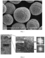
- the high-nickel low-cobalt cathode material prepared in Example 1 was subjected to SEM, TEM, and XRD tests. Results are shown in FIGS. 1 to 3 . It can be seen from FIG. 1 that the high-nickel low-cobalt cathode material prepared in Example 1 was spherical. It can be seen from FIG. 2 that the first coating layer was formed on the surface of the cathode material matrix of Example 1, the second coating layer was formed on the surface of the first coating layer, the first coating layer was of spinel phase, and the second coating layer was of halite phase. Since the mass percentage contents of the first coating layer and the second coating layer in the high-nickel low-cobalt cathode material prepared in Example 1 were relatively low, no peak shapes of the first coating layer and the second coating layer appear in FIG. 3 .
- the high-nickel low-cobalt cathode materials prepared in Examples 2 to 6 were also subjected to SEM, TEM, and XRD tests, and results thereof are similar to the test results of Example 1.
- the high-nickel low-cobalt cathode materials prepared in Examples 1 to 6 and Comparative Examples 1 to 3 were made into cathode sheets.
- the above cathode sheet were respectively assembled into button batteries, and then initial discharging specific capacity, initial efficiency, and capacity retention ratio after 200 cycles were tested.
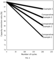
- Test conditions of the initial capacity and cycle of the button batteries were LR 2032, 0.3 C, 2.5 V to 4.25 V, and vs.Li + /Li, and test results are shown in Table 1 and FIG. 4 .
- 0.33CC/XCD means that the button battery is charged to 4.25 V at a current of 0.33 C at a constant current and then discharged to 2.5 V at a current of XC at a constant current.
- Example 1 222.2 91.14 95.72
- Example 2 221.7 91.06 95.87
- Example 3 223.4 90.89 95.38
- Example 4 222.5 91.22 95.63
- Example 5 221.9 90.97 95.58
- Example 6 222.3 91.15 95.63 Comparative Example 1 215.4 88.35 78.22 Comparative Example 2 211.7 89.67 85.20 Comparative Example 3 214.6 90.92 90.36
- Table 3 Group 0.33CD (%) 0.5CD (%) 1.0CD (%) 2.0CD (%)
- Example 1 100 98.9 95.3 88.7
- Example 2 100 98.6 95.7 89.4
- Example 3 100 99.0 96.2 90.1
- Example 4 100 98.7 95.1 88.4
- Example 5 100 98.3 95.5 89.2
- Example 6 100 99.0 95.2 88.3
- Comparative Example 1 100 94.7 91.2 75.3 Comparative Example 2 100 95.6 91.4 76.
- Comparative Example 1 since phosphorus sulfide treatment was not performed, the residual alkali was relatively high and seriously blocked the lithium ion transmission channels, so that the initial efficiency of the corresponding battery was reduced, and the discharging specific capacity was reduced. Meanwhile, since no coating layer was formed, the layered structure was gradually decomposed from the surface to the inward during charging and discharging, resulting in relatively poor capacity retention ratio.
- the high-nickel low-cobalt cathode material treated with the sulfur phosphorus compound in the present disclosure has the advantages of high initial discharging specific capacity, good long cycle performance, and good rate performance.
- the high-nickel low-cobalt cathode material provided in the present disclosure includes the cathode material matrix, the first coating layer, and the second coating layer.
- the high-nickel low-cobalt cathode material provided in the present disclosure can prevent the electrolytic solution from corroding the cathode material matrix, protect integrity of bulk phase structure, and effectively inhibit decomposition and collapse of layered structure of the high-nickel low-cobalt cathode material during the charging and discharging cycles, thereby improving the long cycle performance of the high-nickel low-cobalt cathode material. Therefore, the present disclosure has excellent applicability.
Landscapes
- Chemical & Material Sciences (AREA)
- Chemical Kinetics & Catalysis (AREA)
- Electrochemistry (AREA)
- General Chemical & Material Sciences (AREA)
- Engineering & Computer Science (AREA)
- Inorganic Chemistry (AREA)
- Manufacturing & Machinery (AREA)
- Materials Engineering (AREA)
- Organic Chemistry (AREA)
- Composite Materials (AREA)
- Battery Electrode And Active Subsutance (AREA)
Abstract
Description
- The present disclosure claims priority to the
Chinese patent application with the filing No. 202211302463.4, filed with the Chinese Patent Office on October 24, 2022 - The present disclosure relates to the technical field of lithium ion batteries, and particularly to a high-nickel low-cobalt cathode material and a preparation method and use thereof.
- Matured application of lithium ion batteries to electric vehicles and electric tools makes the development of current power batteries pursue higher endurance and longer service lifetime. At present, the type of high nickel and low cobalt, and the type of medium nickel and high voltage have become two major application research aspects of cathode materials of lithium ion battery. The high-nickel low-cobalt cathode material has obvious advantages due to low cost and high energy density thereof. However, the high-nickel low-cobalt cathode material causes rapid attenuation of long cycle capacity of batteries due to transition metal migration, structural transformation, surface oxygen loss and so on. This greatly limits further development of high nickel and low cobalt in lithium ion power batteries.
- Based on this, it is necessary to provide a high-nickel low-cobalt cathode material and a preparation method and use thereof, so as to prevent an electrolytic solution from corroding a cathode material matrix, protect integrity of bulk phase structure, and effectively inhibit decomposition and collapse of layered structure of the high-nickel low-cobalt cathode material during charging and discharging cycles, thereby improving the long cycle performance of the high-nickel low-cobalt cathode material.
- An embodiment of the present disclosure provides a high-nickel low-cobalt cathode material, including a cathode material matrix, a first coating layer, and a second coating layer, wherein the first coating layer is coated on a surface of the cathode material matrix, and the second coating layer is coated on a surface of the first coating layer;
- the first coating layer includes a material of a chemical formula LiaNibCocM1- b-cOd, where M includes one or two of Mn and Al, 0.2≤a≤1, 0.88<b≤0.98, 0≤c<0.06, b+c<1, and 1.6≤d≤2; and
- a material of the second coating layer includes one or more of Li3PO4, Li2SO4, and LiPOs.
- Optionally, the cathode material matrix includes a material of a chemical formula LiNixCoyM1-x-yO2, where M includes one or more of Mn and Al, 0.88<x≤0.98, 0≤y<0.06, and x+y≤1.
- Optionally, a total mass of the first coating layer and the second coating layer: a mass of the cathode material matrix is (0.0001 to 0.005): 1.
- Optionally, the first coating layer has a thickness of 5 nm to 10 nm.
- Optionally, the first coating layer is of spinel phase.
- Optionally, the second coating layer has a thickness of 2 nm to 5 nm.
- Optionally, the second coating layer is of halite phase.
- The present disclosure further provides a preparation method of the above high-nickel low-cobalt cathode material, including following steps:
- providing a cathode material matrix; and
- mixing the cathode material matrix with a sulfur phosphorus compound, and then performing a first calcination treatment, so as to form the first coating layer and the second coating layer on a surface of the cathode material matrix.
- Optionally, phosphorous element in the sulfur phosphorus compound: the cathode material matrix is (0.001 to 0.01): 1 in molar ratio.
- Optionally, the sulfur phosphorus compound comprises one or more of phosphorus sulfide and phosphorus trisulfide.
- Optionally, process conditions of the first calcination treatment include: a first calcination temperature of 260 °C to 600 °C, and first calcination time of 4 h to 12 h.
- Optionally, the preparation method of the cathode material matrix includes following steps:
- S1, mixing a lithium source, a metal compound, and a cathode material matrix precursor, to obtain a mixture; and
- S2, subjecting the mixture to a second calcination treatment.
- Optionally, the cathode material matrix precursor includes a material of a chemical formula NixCoyM1-x-y(OH)2, where M includes one or more of Mn and Al, 0.88<x≤0.98, 0≤y<0.06, and x+y<1.
- Optionally, the lithium source includes one or more of lithium hydroxide and lithium carbonate.
- Optionally, the metal compound includes a compound of one or more of Mg, Ti, Zr, Y, Nb, W, Ce, Sb, Sr, and Ta.
- Optionally, in step S2, a temperature of the second calcination treatment is 600 °C to 1000 °C, and time of the second calcination treatment is 4 h to 20 h.
- Optionally, in molar ratio, lithium ion in the lithium source: metal element in the metal compound: the cathode material matrix precursor is (1.00 to 1.08): (0 to 0.02): 1 in step S1.
- The present disclosure further provides a cathode sheet, including the above high-nickel low-cobalt cathode material or the high-nickel low-cobalt cathode material prepared by the above preparation method.
- The present disclosure further provides a lithium ion battery, including the above cathode sheet.
- The present disclosure further provides a power consumption device, including the above lithium ion battery.
- Compared with the conventional technologies, the high-nickel low-cobalt cathode material and the preparation method and use thereof at least have the following advantages:
- (1) the above first coating layer and second coating layer can prevent electrochemical decomposition behaviors of (010) active crystal plane of the high-nickel low-cobalt cathode material during charging and discharging, thus achieving effective protection to the active crystal face. Meanwhile, the first coating layer and the second coating layer can prevent decomposition of the electrolytic solution and corrosion of the electrolytic solution to the cathode material matrix, protect integrity of layered structure of bulk phase of the high-nickel low-cobalt cathode material, and effectively prevent decomposition of the bulk phase structure, thus further improving discharging specific capacity, initial efficiency, cycle life, and rate performance of the lithium ion battery; and
- (2) by forming the first coating layer and the second coating layer through the first calcination treatment, the above high-nickel low-cobalt cathode material solves the problems that the conventional high-nickel cathode material has high residual alkali, and lithium-ion transmission channels are blocked to hinder exertion of performance, omits the conventional water washing process, reduces production costs, and also makes it easy to control the process.
-
-
FIG. 1 is an SEM diagram of a high-nickel low-cobalt cathode material prepared in Example 1 of the present disclosure; -
FIG. 2 is a TEM diagram of the high-nickel low-cobalt cathode material prepared in Example 1 of the present disclosure; -
FIG. 3 is an XRD diagram of the high-nickel low-cobalt cathode material prepared in Example 1 of the present disclosure; and -
FIG. 4 is a comparison diagram of cycle performance of high-nickel low-cobalt cathode materials prepared in Example 1 and Comparative Examples 1 to 3 of the present disclosure. - In order to facilitate understanding the present disclosure, the present disclosure will be described more comprehensively below. Preferred examples of the present disclose are given in specific examples. However, the present disclosure can be realized in many different forms, and is not limited to the examples described herein. In contrast, these examples are provided for the purpose of making the contents disclosed in the present disclosure more thorough and more comprehensive.
- Unless otherwise defined, all of the technical and scientific terms used herein have the same meanings as those generally understood by those skilled in the art of the present disclosure. Terms used herein in the description of the present disclosure are only for the purpose of describing specific examples, rather than limiting the present disclosure. The term "multiple (a plurality of)" in the present disclosure means at least two, such as two, three, etc., unless otherwise clearly and specifically defined.
- In the present disclosure, for the technical features described in an open manner, a closed technical solution composed of the listed features is included, and an open technical solution containing the listed features is also included.
- An embodiment of the present disclosure provides a high-nickel low-cobalt cathode material, including a cathode material matrix, a first coating layer, and a second coating layer, wherein the first coating layer is coated on a surface of the cathode material matrix, and the second coating layer is coated on a surface of the first coating layer.
- The first coating layer includes a material of a chemical formula LiaNibCocM1-b-cOd, where M includes one or two of Mn and Al, 0.2≤a≤1, 0.88<b≤0.98, 0≤c<0.06, b+c<1, and 1.6≤d≤2.
- A material of the second coating layer includes one or more of Li3PO4, Li2SO4, and LiPOs.
- The above first coating layer can effectively isolate the cathode material matrix from an external environment. Li3PO4, Li2SO4, and LiPO3 of the second coating layer can prevent electrochemical decomposition behaviors of (010) active crystal plane of the high-nickel low-cobalt cathode material during charging and discharging, thus achieving effective protection to the active crystal face. Meanwhile, the first coating layer and the second coating layer can prevent decomposition of an electrolytic solution and corrosion of the electrolytic solution to the cathode material matrix, protect the integrity of layered structure of bulk phase of the high-nickel low-cobalt cathode material, and effectively prevent decomposition of the bulk phase structure, further improving discharging specific capacity, initial efficiency, and cycle life of the lithium ion battery. It can be understood that a may be any value from 0.2 to 1, for example: 0.2, 0.3, 0.4, 0.5, 0.6, 0.7, 0.8, 0.9 or 1; b may be, for example, 0.89, 0.90, 0.91, 0.92, 0.93, 0.94, 0.95, 0.96, 0.97 or 0.98; c may be, for example, 0.01, 0.02, 0.03, 0.04 or 0.05; and d may be any value from 1.6 to 2, for example, 1.6, 1.62, 1.65, 1.67, 1.7, 1.8, 1.9 or 2.
- In some embodiments, the cathode material matrix includes a material of a chemical formula LiNixCoyM1-x-yO2, where M includes one or more of Mn and Al, 0.88<x≤0.98, 0≤y<0.06, and x+y≤1. It can be understood that x may be, for example, 0.89, 0.90, 0.91, 0.92, 0.93, 0.94, 0.95, 0.96, 0.97, 0.98, and y may be, for example, 0.01, 0.02, 0.03, 0.04 or 0.05.
- In some embodiments, a total mass of the first coating layer and the second coating layer: a mass of the cathode material matrix is (0.0001 to 0.005): 1. It can be understood that the ratio of the total mass of the first coating layer and the second coating layer to the mass of the cathode material matrix may be, for example, 0.0001:1, 0.00012:1, 0.00013:1, 0.00015:1, 0.00018:1, 0.0002:1, 0.00022:1, 0.00025:1, 0.00028:1, 0.0003:1, 0.00035:1, 0.0004:1, 0.00045:1 or 0.0005:1.
- In some embodiments, the first coating layer has a thickness of 5 nm to 10 nm. It can understood that the thickness of the first coating layer may be, for example, 5 nm, 5.5 nm, 6 nm, 6.5 nm, 7 nm, 7.5 nm, 8 nm, 8.5 nm, 9 nm, 9.5 nm, or 10 nm, and the thickness of the first coating layer also may be other values from 5 nm to 10 nm.
- In some embodiments, the first coating layer is of spinel phase. It should be noted that a fast ionic conductor coating layer is formed on the surface of the first coating layer having the spinel phase, which can prevent the electrochemical decomposition behaviors of the (010) active crystal plane of the high-nickel low-cobalt cathode material during charging and discharging, thereby achieving effective protection to the active crystal face.
- Further, the second coating layer is of halite phase. The above first coating layer and second coating layer being of the spinel phase and the halite phase greatly improves the stability of the surface structure of the high-nickel low-cobalt cathode material, thereby improving the electrochemical performance.
- In some embodiments, the second coating layer has a thickness of 2 nm to 5 nm. It can be understood that the thickness of the second coating layer may be, for example, 2 nm, 2.5 nm, 3 nm, 3.5 nm, 4 nm, 4.5 nm, or 5 nm, and the thickness of the second coating layer also may be other values from 2 nm to 5 nm.
- Another embodiment of the present disclosure provides a preparation method of the above high-nickel low-cobalt cathode material, including the following steps:
- providing a cathode material matrix; and
- mixing the cathode material matrix with a sulfur phosphorus compound, and then performing a first calcination treatment, so as to form a first coating layer and a second coating layer on a surface of the cathode material matrix.
- The above cathode material matrix includes a material of a chemical formula LiNixCoyM1-x-yO2, where M includes one or more of Mn and Al, 0.88<x≤0.98, 0≤y<0.06, and x+y≤1. The above cathode material reacts with the sulfur phosphorus compound when being subjected to the first calcination treatment, thereby forming the first coating layer and the second coating layer. The formed first coating layer includes a material of a chemical formula LiaNibCocM1-b-cOd, where M includes one or both of Mn and Al, where 0.2≤a≤1, 0.88<b≤0.98, 0≤c<0.06, b+c<1, and 1.6≤d≤2. A material of the second coating layer includes one or more of Li3PO4, Li2SO4, and LiPOs. The coating of the cathode material matrix can be completed through the first calcination treatment, thereby reducing the conventional water washing and drying processes, reducing production costs, facilitating industrial production, and meanwhile solving the problems that the conventional high-nickel cathode material has high residual alkali, and lithium-ion transmission channels are blocked to hinder exertion of performance. The above sulfur phosphorus compound reconstructs the layered phase of the surface of the cathode material matrix into a more stable spinel phase through strong lithium deintercalation and deoxygenation under thermodynamic equilibrium, and meanwhile, multiple types of amorphous fast ionic conductor coating layers are formed on an outer surface of the first coating layer, which can prevent the electrochemical decomposition behaviors of the (010) active crystal plane of the material during charging and discharging, and achieve the effective protection to the active crystal face. The above first coating layer and second coating layer can prevent decomposition of an electrolytic solution and corrosion of the electrolytic solution to the cathode material matrix, protect the integrity of layered structure of bulk phase of the high-nickel low-cobalt cathode material, and effectively prevent decomposition of the bulk phase structure, further improving discharging specific capacity, initial efficiency, and cycle life of the battery.
- In some embodiments, phosphorous element in the sulfur phosphorus compound: the cathode material matrix is (0.001 to 0.01): 1 in molar ratio. It can be understood that the molar ratio of the phosphorous element in the sulfur phosphorus compound to the cathode material matrix may be, for example, 0.001:1, 0.002:1, 0.003:1, 0.004:1, 0.005:1, 0.006:1, 0.007:1, 0.008:1, 0.009:1 or 0.01:1.
- Specifically, the sulfur phosphorus compound includes one or more of phosphorus sulfide and phosphorus pentasulfide.
- In some embodiments, process conditions of the first calcination treatment include: a first calcination temperature of 260 °C to 600 °C, and first calcination time of 4 h to 12 h. It can be understood that the first calcination temperature may be any value from 260 °C to 600 °C, for example: 260 °C, 280 °C, 300 °C, 320 °C, 340 °C, 360 °C, 380 °C, 400 °C, 450 °C, 500 °C, 550 °C, 600 °C; and the first calcination time may be any value from 4 h to 12 h, and may be, for example, 4 h, 5 h, 6 h, 7 h, 8 h, 9 h, 10 h.
- In some embodiments, the preparation method of a cathode material matrix includes the following steps:
- S1, mixing a lithium source, a metal compound, and a cathode material matrix precursor, to obtain a mixture; and
- S2, subjecting the mixture to a second calcination treatment, a crushing treatment, and a sieving treatment in turn, to obtain the cathode material matrix.
- It should be noted that for the above cathode material matrix obtained after the sieving treatment, it is feasible that a median particle size D50 thereof is 1.2 µm to 15 µm. It can be understood that the median particle size D50 of the above cathode material matrix obtained after the sieving treatment may be, for example, 1.2 µm, 1.5 µm, 2 µm, 3 µm, 4 µm, 5 µm, 6 µm, 7 µm, 8 µm, 9 µm, 10 µm, 11 µm, 12 µm, 13 µm, 14 µm or 15 µm.
- In some embodiments, the cathode material matrix precursor includes a material of a chemical formula NixCoyM1-x-y(OH)2, where M includes one or more of Mn and Al, 0.88<x≤0.98, 0≤y<0.06, and x+y<1. It can be understood that x may be, for example, 0.89, 0.90, 0.91, 0.92, 0.93, 0.94, 0.95, 0.96, 0.97 or 0.98, and y may be, for example, 0.01, 0.02, 0.03, 0.04 or 0.05.
- In some embodiments, the lithium source includes one or more of lithium hydroxide and lithium carbonate.
- In some embodiments, the metal compound includes a compound of one or more of Mg, Ti, Zr, Y, Nb, W, Ce, Sb, Sr, and Ta. It should be noted that the metal compound may be oxide, hydroxide or carbonate of the above metals, for example, MgO, TiO2, ZrO2, Y2O3, Nb2O5, WO3, CeO2, Sb2O3, Sb2O5, SrO, Ta2O5, Mg(OH)2, Zr(OH)4, Ti(OH)4, Sr(OH)2, MgCO3, SrCO3 or Zr3(CO3)O5.
- In some embodiments, in step S2, a temperature of the second calcination treatment is 600 °C to 1000 °C, and time of the second calcination treatment is 4 h to 20 h. It can be understood that the temperature of the second calcination treatment may be any value from 600 °C to 1000 °C, for example, it may be 600 °C, 650 °C, 700 °C, 750 °C, 800 °C, 850 °C, 900 °C, 950 °C or 1000 °C; and the time of the second calcination treatment may be 4 h, 5 h, 6 h, 7 h, 8 h, 9 h, 10 h, 11 h, 12 h, 13 h, 14 h, 15 h, 16 h, 17 h, 18 h, 19 h or 20 h, and also may be other values from 4 h to 20 h.
- In some embodiments, in molar ratio, lithium ion in the lithium source: metal element in the metal compound: the cathode material matrix precursor is (1.00 to 1.08): (0 to 0.02): 1 in step S1. It can be understood that in molar ratio, the lithium ion in the lithium source: the metal element in the metal compound: the cathode material matrix precursor in step S1 may be 1.00:0.01:1, 1.01:0.012:1, 1.02:0.013:1, 1.03:0.014:1, 1.04:0.015:1, 1.05:0.016:1, 1.06:0.017:1, 1.07:0.018:1, 1.08:0.019:1 or 1.08:0.02:1, etc.
- Another embodiment of the present disclosure provides a cathode sheet, including the above high-nickel low-cobalt cathode material or the high-nickel low-cobalt cathode material prepared by the above preparation method.
- It should be noted that, the above cathode sheet includes a cathode current collector and a cathode active substance layer disposed on at least one surface of the cathode current collector. The cathode active substance layer includes a cathode active substance, a conductive agent, and a binder. The cathode active substance can use the above high-nickel low-cobalt cathode material or the high-nickel low-cobalt cathode material prepared by the above preparation method. The conductive agent and the binder are not particularly limited, and the conductive agents and the binders commonly used in the art can be used. For example, the conductive agent may be a material such as carbon black, acetylene black, ketjen black, carbon fiber, carbon nanotube, and graphene, or a mixture thereof, and the binder includes, but is not limited to, vinylidene fluoride, polyvinyl alcohol, carboxymethyl cellulose, hydroxypropyl cellulose, hydroxyethyl cellulose, polytetrafluoroethylene, etc. A preparation process of the above cathode sheet includes, but is not limited to, coating a slurry obtained by mixing the cathode active substance, the conductive agent, the binder, and a solvent on the cathode current collector, and performing steps such as a drying process, a rolling process, and a slicing process in turn to obtain the cathode sheet.
- Another embodiment of the present disclosure provides a lithium ion battery, including the above cathode sheet.
- A preparation method of the above lithium ion battery includes, but is not limited to: laminating or winding the above cathode sheet, a separator, and a negative electrode sheet to obtain an electrode set, and assembling the electrode set with a case and then injecting an electrolytic solution into the case to obtain the lithium ion battery. A PE film or a PP film can be selected as the separator, and graphite, soft carbon, hard carbon, composite carbon, silicon material or metallic lithium, etc. can be selected as the negative electrode material.
- Another embodiment of the present disclosure provides a power consumption device, including the above lithium ion battery.
- The above power consumption device includes, but is not limited to, a bicycle, a calculator, a portable audio recorder, a radio, a backup power supply, a lighting equipment, a toy, an electric tool, a notebook computer, a mobile computer, a game machine, a liquid crystal television, a motorcycle, a motor, an automobile, a camera, and the like.
- The present disclosure is further described in detail below in combination with specific embodiments, but the embodiments of the present disclosure are not limited thereto.
- Experimental raw materials used in the following examples and comparative examples are either commercially available or prepared according to conventional methods well known to those skilled in the art.
- In the present example, a lithium source was LiOH, a metal compound was ZrO2, and a high-nickel low-cobalt cathode material matrix precursor was Ni0.95Co0.03Mn0.02(OH)2.
- A preparation method of a high-nickel low-cobalt cathode material included the following steps:
- S1, mixing LiOH, ZrO2, and Ni0.95Co0.03Mn0.02(OH)2 according to a molar ratio of 1.03:0.003:1, and fully mixing them to obtain a mixture;
- S2, calcining the mixture obtained in step S1 at 780 °C for 15 hours, and then performing a crushing treatment and a sieving treatment in turn, to obtain a high-nickel low-cobalt cathode material matrix, which included LiNi0.95Co0.03Mn0.02O2; and
- S3, fully mixing the high-nickel low-cobalt cathode material matrix obtained in step S2 with phosphorus sulfide with a molar ratio of the high-nickel low-cobalt cathode material matrix obtained in step S2 to phosphorus element in the phosphorus sulfide being 1:0.003, and then calcining mixture at 400 °C for 10 h, so as to form a first coating layer and a second coating layer on a surface of the high-nickel low-cobalt cathode material matrix, and then performing the crushing treatment and the sieving treatment, to obtain the high-nickel low-cobalt cathode material, wherein a material of the first coating layer included LiNi0.95Co0.03Mn0.02O2, and a material of the second coating layer included Li3PO4, Li2SO4, and LiPOs.
- In the present example, a lithium source was LiOH, a metal compound was TiO2, and a high-nickel low-cobalt cathode material matrix precursor was Ni0.94Co0.03Al0.03(OH)2.
- A preparation method of a high-nickel low-cobalt cathode material included the following steps:
- S1, mixing LiOH, TiO2, and Ni0.94Co0.03Al0.03(OH)2 according to a molar ratio of 1.03:0.005:1, and fully mixing them to obtain a mixture;
- S2, calcining the mixture obtained in step S1 at 800 °C for 13 hours, and then performing a crushing treatment and a sieving treatment in turn, to obtain a high-nickel low-cobalt cathode material matrix, which included LiNi0.94Co0.03Al0.03O2; and
- S3, fully mixing the high-nickel low-cobalt cathode material matrix obtained in step S2 with phosphorus sulfide with a molar ratio of the high-nickel low-cobalt cathode material matrix obtained in step S2 to phosphorus element in the phosphorus sulfide being 1:0.004, and then calcining mixture at 450 °C for 8 h, so as to form a first coating layer and a second coating layer on a surface of the high-nickel low-cobalt cathode material matrix, and then performing the crushing treatment and the sieving treatment, to obtain the high-nickel low-cobalt cathode material, wherein a material of the first coating layer included LiNi0.94Co0.03Al0.03O2, and a material of the second coating layer included Li3PO4, Li2SO4, and LiPOs.
- In the present example, a lithium source was LiOH, a metal compound was SrCO3, and a high-nickel low-cobalt cathode material matrix precursor was Ni0.96Co0.02Mn0.02(OH)2.
- A preparation method of a high-nickel low-cobalt cathode material included the following steps:
- S1, mixing LiOH, SrCO3, and Ni0.96Co0.02Mn0.02(OH)2 according to a molar ratio of 1.03:0.002:1, and fully mixing them to obtain a mixture;
- S2, calcining the mixture obtained in step S1 at 760 °C for 10 hours, and then performing a crushing treatment and a sieving treatment in turn, to obtain a high-nickel low-cobalt cathode material matrix, which included LiNi0.96Co0.02Mn0.02O2; and
- S3, fully mixing the high-nickel low-cobalt cathode material matrix obtained in step S2 with phosphorus sulfide with a molar ratio of the high-nickel low-cobalt cathode material matrix obtained in step S2 to phosphorus element in the phosphorus sulfide being 1:0.006, and then calcining mixture at 500 °C for 12 h, so as to form a first coating layer and a second coating layer on a surface of the high-nickel low-cobalt cathode material matrix, and then performing the crushing treatment and the sieving treatment, to obtain the high-nickel low-cobalt cathode material, wherein a material of the first coating layer included LiNi0.96Co0.02Mn0.02O2, and a material of the second coating layer included Li3PO4, Li2SO4, and LiPOs.
- In the present example, a lithium source was LiOH, metal compounds were ZrO2 and SrCOs, and a high-nickel low-cobalt cathode material matrix precursor was Ni0.95Co0.02Mn0.02Al0.01(OH)2.
- A preparation method of a high-nickel low-cobalt cathode material included the following steps:
- S1, mixing LiOH, ZrO2, SrCOs, and Ni0.95Co0.02Mn0.02Al0.01(OH)2 according to a molar ratio of 1.03:0.002:0.002:1, and fully mixing them to obtain a mixture;
- S2, calcining the mixture obtained in step S1 at 750 °C for 10 hours, and then performing a crushing treatment and a sieving treatment in turn, to obtain a high-nickel low-cobalt cathode material matrix, which included LiNi0.95Co0.02Mn0.02Al0.01O2; and
- S3, fully mixing the high-nickel low-cobalt cathode material matrix obtained in step S2 with phosphorus sulfide with a molar ratio of the high-nickel low-cobalt cathode material matrix obtained in step S2 to phosphorus element in the phosphorus sulfide being 1:0.003:0.003, and then calcining mixture at 550 °C for 6 h, so as to form a first coating layer and a second coating layer on a surface of the high-nickel low-cobalt cathode material matrix, and then performing the crushing treatment and the sieving treatment, to obtain the high-nickel low-cobalt cathode material, wherein a material of the first coating layer included LiNi0.95Co0.02Mn0.02Al0.01O2, and a material of the second coating layer included Li3PO4, Li2SO4, and LiPOs.
- Substantially the same as Example 1, the difference lies in that, in step S3, the high-nickel low-cobalt cathode material matrix and the phosphorus sulfide were fully mixed according to a molar ratio of the high-nickel low-cobalt cathode material matrix to phosphorus element in the phosphorus sulfide being 1 :0.001. In the high-nickel low-cobalt cathode material, the material of the first coating layer included LiNi0.95Co0.03Mn0.02O2, and a material of the second coating layer included Li3PO4, Li2SO4, and LiPOs.
- Substantially the same as Example 1, the difference lies in that the high-nickel low-cobalt cathode material matrix and the phosphorus sulfide were fully mixed according to a molar ratio of the high-nickel low-cobalt cathode material matrix to phosphorus element in the phosphorus sulfide being 1:0.01. In the high-nickel low-cobalt cathode material, the material of the first coating layer included LiNi0.95Co0.03Mn0.02O2, and a material of the second coating layer included Li3PO4, Li2SO4, and LiPOs.
- Substantially the same as Example 1, the difference lies in that step S3 was replaced by: calcining the high-nickel low-cobalt cathode material matrix obtained in step S2 at 400 °C for 10 h, and then performing a crushing treatment and a sieving treatment, to obtain the high-nickel low-cobalt cathode material.
- Substantially the same as Example 1, the difference lies in that step S3 was replaced by: stirring and washing the high-nickel low-cobalt cathode material matrix obtained in step S2 and purified water at a mass ratio 1:1, then drying at 150 °C for 2 h to obtain an intermediate, calcining the intermediate at 400 °C for 10 h, and then performing the crushing treatment and the sieving treatment, to obtain the high-nickel low-cobalt cathode material.
- Substantially the same as Example 1, the difference lies in that step S3 was replaced by: stirring and washing the high-nickel low-cobalt cathode material matrix obtained in step S2 and purified water according to a mass ratio 1:1, then drying at 150 °C for 2 h to obtain an intermediate, fully mixing the intermediate with phosphorus sulfide at a molar ratio of the intermediate to phosphorus element in the phosphorus sulfide being 1 :0.003, and calcining at 400 °C for 10 h, to obtain the high-nickel low-cobalt cathode material.
- The high-nickel low-cobalt cathode material prepared in Example 1 was subjected to SEM, TEM, and XRD tests. Results are shown in
FIGS. 1 to 3 . It can be seen fromFIG. 1 that the high-nickel low-cobalt cathode material prepared in Example 1 was spherical. It can be seen fromFIG. 2 that the first coating layer was formed on the surface of the cathode material matrix of Example 1, the second coating layer was formed on the surface of the first coating layer, the first coating layer was of spinel phase, and the second coating layer was of halite phase. Since the mass percentage contents of the first coating layer and the second coating layer in the high-nickel low-cobalt cathode material prepared in Example 1 were relatively low, no peak shapes of the first coating layer and the second coating layer appear inFIG. 3 . - The high-nickel low-cobalt cathode materials prepared in Examples 2 to 6 were also subjected to SEM, TEM, and XRD tests, and results thereof are similar to the test results of Example 1.
- The residual alkali (LiOH and Li2CO3) content in the high-nickel low-cobalt cathode materials prepared in Examples 1 to 6 and Comparative Examples 1 to 3 was tested by a titration method, and the Li element content in the high-nickel low-cobalt cathode materials was tested by ICP-AES. Test results are shown in Table 1.
- The high-nickel low-cobalt cathode materials prepared in Examples 1 to 6 and Comparative Examples 1 to 3 were made into cathode sheets. The cathode sheets were prepared according to a mass ratio of the high-nickel low-cobalt cathode material: conductive agent: PVDF=95:2.5:2.5. The above cathode sheet were respectively assembled into button batteries, and then initial discharging specific capacity, initial efficiency, and capacity retention ratio after 200 cycles were tested. Test conditions of the initial capacity and cycle of the button batteries were LR 2032, 0.3 C, 2.5 V to 4.25 V, and vs.Li+/Li, and test results are shown in Table 1 and
FIG. 4 . Test conditions of the rate capability were LR 2032, 0.33CC/XCD (X=0.33, 0.5, 1.0, 2.0), 2.5 V to 4.25 V, and vs.Li+/Li, and test results are shown in Table 2 and Table 3. In the above, 0.33CC/XCD means that the button battery is charged to 4.25 V at a current of 0.33 C at a constant current and then discharged to 2.5 V at a current of XC at a constant current.Table 1 Group LiOH (ppm) Li2CO3 (ppm) Li element (%) Example 1 3125 852 7.12 Example 2 3022 886 7.11 Example 3 3056 891 7.12 Example 4 3072 875 7.10 Example 5 3436 1129 7.13 Example 6 2712 807 7.11 Comparative Example 1 3665 2364 7.13 Comparative Example 2 2272 804 6.72 Comparative Example 3 1881 472 6.71 - It can be seen from the data in Table 1 that, compared with Example 1, the contents of LiOH and Li2CO3 in Comparative Example 1 were significantly increased, indicating that after the high-nickel low-cobalt cathode material prepared in Example 1 was treated with phosphorus sulfide, the residual alkali content can be obviously reduced without losing the content of Li element. Although the contents of LiOH and Li2CO3 in the high-nickel low-cobalt cathode material prepared in Comparative Example 2 were reduced after the water-washing and drying processes, the content of Li element therein was reduced. Compared with Comparative Example 2, the residual alkali of the high-nickel low-cobalt cathode material prepared in Comparative Example 3 was reduced, and the Li element content was not lost.
Table 2 Group Initial Discharging Specific Capacity (mAh/g) Initial Efficiency (%) 200-cycle Capacity Retention Ratio (%) Example 1 222.2 91.14 95.72 Example 2 221.7 91.06 95.87 Example 3 223.4 90.89 95.38 Example 4 222.5 91.22 95.63 Example 5 221.9 90.97 95.58 Example 6 222.3 91.15 95.63 Comparative Example 1 215.4 88.35 78.22 Comparative Example 2 211.7 89.67 85.20 Comparative Example 3 214.6 90.92 90.36 Table 3 Group 0.33CD (%) 0.5CD (%) 1.0CD (%) 2.0CD (%) Example 1 100 98.9 95.3 88.7 Example 2 100 98.6 95.7 89.4 Example 3 100 99.0 96.2 90.1 Example 4 100 98.7 95.1 88.4 Example 5 100 98.3 95.5 89.2 Example 6 100 99.0 95.2 88.3 Comparative Example 1 100 94.7 91.2 75.3 Comparative Example 2 100 95.6 91.4 76.8 Comparative Example 3 100 96.1 92.6 79.2 - It can be seen from the data in Tables 2 and 3 and
FIG. 4 that, the high-nickel low-cobalt cathode materials prepared in Examples 1 to 6 of the present disclosure had good dynamic performance, the assembled batteries had high discharging specific capacity, high initial efficiency, good cycle performance, and excellent rate performance, thus having a wide application prospect in the field of lithium ion batteries. - In Comparative Example 1, since phosphorus sulfide treatment was not performed, the residual alkali was relatively high and seriously blocked the lithium ion transmission channels, so that the initial efficiency of the corresponding battery was reduced, and the discharging specific capacity was reduced. Meanwhile, since no coating layer was formed, the layered structure was gradually decomposed from the surface to the inward during charging and discharging, resulting in relatively poor capacity retention ratio.
- In Comparative Example 2, the Li element content was seriously lost due to the water washing and drying processes, resulting in significant decrease in the initial capacity.
- The initial discharging specific capacity and cycle retention ratio in Comparative Example 3 were improved compared with those in Comparative Example 1. However, after the water washing and drying processes, the Li element content in the high-nickel low-cobalt cathode material and the layered structure of the coating layer were destroyed and lost to a certain extent, which results in the initial capacity and cycle retention ratio being lower than those in Example 1.
- In conclusion, it can be indicated that the high-nickel low-cobalt cathode material treated with the sulfur phosphorus compound in the present disclosure has the advantages of high initial discharging specific capacity, good long cycle performance, and good rate performance.
- Various technical features in the above examples can be combined arbitrarily, and for the sake of concise description, not all possible combinations of the various technical features in the above examples are described, while the combinations of these technical features should be considered as within the scope of the present description as long as there is no contradiction.
- The above examples merely express several implementation modes of the present disclosure, of which the description is relatively specific and detailed, but they should not be thus construed as limitation to the patent scope of the present disclosure. It should be noted that those ordinarily skilled in the art still could make several modifications and improvements without departing from the concept of the present disclosure, all of which fall within the scope of protection of the present disclosure. Therefore, the scope of protection of the present patent should be determined by the enclosed claims. The description and the attached drawings can be used to explain the contents of the claims.
- The high-nickel low-cobalt cathode material provided in the present disclosure includes the cathode material matrix, the first coating layer, and the second coating layer. The high-nickel low-cobalt cathode material provided in the present disclosure can prevent the electrolytic solution from corroding the cathode material matrix, protect integrity of bulk phase structure, and effectively inhibit decomposition and collapse of layered structure of the high-nickel low-cobalt cathode material during the charging and discharging cycles, thereby improving the long cycle performance of the high-nickel low-cobalt cathode material. Therefore, the present disclosure has excellent applicability.
Claims (13)
- A high-nickel low-cobalt cathode material, comprising a cathode material matrix, a first coating layer, and a second coating layer, wherein the first coating layer is coated on a surface of the cathode material matrix, and the second coating layer is coated on a surface of the first coating layer;the first coating layer comprises a material of a chemical formula LiaNibCocM1-b-cOd, where M comprises one or two of Mn and Al, 0.2≤a≤1, 0.88<b≤0.98, 0≤c<0.06, b+c<1, and 1.6≤d≤2; anda material of the second coating layer comprises one or more of Li3PO4, Li2SO4, and LiPOs.
- The high-nickel low-cobalt cathode material according to claim 1, wherein the cathode material matrix comprises a material of a chemical formula LiNixCoyM1-x-yO2, where M comprises one or more of Mn and Al, 0.88<x≤0.98, 0≤y<0.06, and x+y≤1.
- The high-nickel low-cobalt cathode material according to claim 1 or 2, having at least one of following features (1) to (5):(1) a total mass of the first coating layer and the second coating layer: a mass of the cathode material matrix is (0.0001 to 0.005): 1;(2) the first coating layer has a thickness of 5 nm to 10 nm;(3) the first coating layer is of spinel phase;(4) the second coating layer has a thickness of 2 nm to 5 nm; and(5) the second coating layer is of halite phase.
- A preparation method of the high-nickel low-cobalt cathode material according to any one of claims 1 to 3, comprising following steps:providing the cathode material matrix; andmixing the cathode material matrix with a sulfur phosphorus compound, and then performing a first calcination treatment, so as to form the first coating layer and the second coating layer on a surface of the cathode material matrix.
- The preparation method according to claim 4, wherein a phosphorous element in the sulfur phosphorus compound: the cathode material matrix is (0.001 to 0.01): 1 in molar ratio.
- The preparation method according to claim 4 or 5, wherein the sulfur phosphorus compound comprises one or more of phosphorus sulfide and phosphorus pentasulfide.
- The preparation method according to claim 4, wherein process conditions of the first calcination treatment comprise: a first calcination temperature of 260 °C to 600 °C, and a first calcination time of 4 h to 12 h.
- The preparation method according to claim 4, wherein a preparation method of the cathode material matrix comprises following steps:S1, mixing a lithium source, a metal compound, and a cathode material matrix precursor, to obtain a mixture; andS2, subjecting the mixture to a second calcination treatment.
- The preparation method according to claim 8, wherein the preparation method of the cathode material matrix comprises at least one of following features (1) to (4):(1) the cathode material matrix precursor comprises a material of a chemical formula NixCoyM1-x-y(OH)2, where M comprises one or more of Mn and Al, 0.88<x≤0.98, 0≤y<0.06, and x+y<1;(2) the lithium source comprises one or more of lithium hydroxide and lithium carbonate;(3) the metal compound comprises a compound of one or more of Mg, Ti, Zr, Y, Nb, W, Ce, Sb, Sr, and Ta; and(4) in step S2, a temperature of the second calcination treatment is 600 °C to 1000 °C, and a time of the second calcination treatment is 4 h to 20 h.
- The preparation method according to claim 8 or 9, wherein in molar ratio, a lithium ion in the lithium source: a metal element in the metal compound: the cathode material matrix precursor is (1.00 to 1.08): (0 to 0.02): 1 in step S1.
- A cathode sheet, comprising the high-nickel low-cobalt cathode material according to any one of claims 1 to 3 or the high-nickel low-cobalt cathode material prepared by the preparation method according to any one of claims 4 to 10.
- A lithium ion battery, comprising the cathode sheet according to claim 11.
- A power consumption device, comprising the lithium ion battery according to claim 12.
Applications Claiming Priority (2)
| Application Number | Priority Date | Filing Date | Title |
|---|---|---|---|
| CN202211302463.4A CN115911302A (en) | 2022-10-24 | 2022-10-24 | High-nickel and low-cobalt cathode material, preparation method and application thereof |
| PCT/CN2023/115137 WO2024087855A1 (en) | 2022-10-24 | 2023-08-28 | High-nickel low-cobalt positive electrode material, preparation method therefor and use thereof |
Publications (2)
| Publication Number | Publication Date |
|---|---|
| EP4383370A1 true EP4383370A1 (en) | 2024-06-12 |
| EP4383370A4 EP4383370A4 (en) | 2024-12-11 |
Family
ID=86492890
Family Applications (1)
| Application Number | Title | Priority Date | Filing Date |
|---|---|---|---|
| EP23793221.5A Pending EP4383370A4 (en) | 2022-10-24 | 2023-08-28 | High-nickel low-cobalt positive electrode material, preparation method therefor and use thereof |
Country Status (3)
| Country | Link |
|---|---|
| EP (1) | EP4383370A4 (en) |
| CN (1) | CN115911302A (en) |
| WO (1) | WO2024087855A1 (en) |
Families Citing this family (3)
| Publication number | Priority date | Publication date | Assignee | Title |
|---|---|---|---|---|
| CN115911302A (en) * | 2022-10-24 | 2023-04-04 | 天津巴莫科技有限责任公司 | High-nickel and low-cobalt cathode material, preparation method and application thereof |
| CN118136808A (en) * | 2024-03-14 | 2024-06-04 | 天津巴莫科技有限责任公司 | A positive electrode material and its preparation method and application |
| CN119118213B (en) * | 2024-11-11 | 2025-03-25 | 赣州市力道新能源有限公司 | Lithium-rich manganese-based positive electrode material and preparation method thereof, and lithium-ion battery |
Family Cites Families (12)
| Publication number | Priority date | Publication date | Assignee | Title |
|---|---|---|---|---|
| CN103247797B (en) * | 2013-05-20 | 2015-10-28 | 深圳市贝特瑞新能源材料股份有限公司 | A kind of anode material for lithium-ion batteries and preparation method thereof |
| US20160079597A1 (en) * | 2014-09-16 | 2016-03-17 | Samsung Electronics Co., Ltd. | All-solid lithium ion secondary battery |
| CN104393234A (en) * | 2014-11-21 | 2015-03-04 | 海宁美达瑞新材料科技有限公司 | Modified lithium ion battery composite positive pole material and preparation method thereof |
| US10340506B2 (en) * | 2014-11-28 | 2019-07-02 | Samsung Electronics Co., Ltd. | Positive electrode for lithium ion secondary battery and lithium ion secondary battery including the same |
| KR102175578B1 (en) * | 2018-11-14 | 2020-11-06 | 삼성에스디아이 주식회사 | Positive active material, method of manufacturing the same and rechargeable lithium battery incluidng the same |
| CN109742347A (en) * | 2018-12-26 | 2019-05-10 | 宁波容百新能源科技股份有限公司 | A kind of nickelic positive electrode and preparation method thereof with uniform clad |
| KR102677615B1 (en) * | 2020-03-27 | 2024-06-21 | 닝더 엠프렉스 테크놀로지 리미티드 | Electrolyte and electrochemical device |
| JPWO2022071192A1 (en) * | 2020-10-02 | 2022-04-07 | ||
| CN112670487B (en) * | 2020-12-28 | 2022-07-15 | 天津巴莫科技有限责任公司 | Multi-dense-coated high-nickel positive electrode material for power and preparation method |
| CN114050271B (en) * | 2022-01-17 | 2022-04-08 | 中创新航科技股份有限公司 | A positive electrode active material with a core-shell structure, a preparation method thereof, and an all-solid-state lithium battery comprising the same |
| CN115064678A (en) * | 2022-06-28 | 2022-09-16 | 天津巴莫科技有限责任公司 | High-nickel low-cobalt positive electrode material, and preparation method and application thereof |
| CN115911302A (en) * | 2022-10-24 | 2023-04-04 | 天津巴莫科技有限责任公司 | High-nickel and low-cobalt cathode material, preparation method and application thereof |
-
2022
- 2022-10-24 CN CN202211302463.4A patent/CN115911302A/en active Pending
-
2023
- 2023-08-28 WO PCT/CN2023/115137 patent/WO2024087855A1/en not_active Ceased
- 2023-08-28 EP EP23793221.5A patent/EP4383370A4/en active Pending
Also Published As
| Publication number | Publication date |
|---|---|
| EP4383370A4 (en) | 2024-12-11 |
| CN115911302A (en) | 2023-04-04 |
| WO2024087855A1 (en) | 2024-05-02 |
Similar Documents
| Publication | Publication Date | Title |
|---|---|---|
| CN103261099B (en) | Composite metal oxide, method for producing composite metal oxide, positive electrode active material for sodium secondary battery, positive electrode for sodium secondary battery, and sodium secondary battery | |
| EP4383370A1 (en) | High-nickel low-cobalt positive electrode material, preparation method therefor and use thereof | |
| JP4237074B2 (en) | Cathode active material for non-aqueous electrolyte secondary battery and non-aqueous electrolyte secondary battery | |
| JP6321973B2 (en) | Composite metal oxide, positive electrode active material for sodium secondary battery, positive electrode for sodium secondary battery, and sodium secondary battery | |
| US7294435B2 (en) | Positive electrode active material for nonaqueous electrolyte secondary battery, positive electrode mixture for nonaqueous electrolyte secondary battery, and nonaqueous electrolyte secondary battery | |
| US20060194114A1 (en) | Positive electrode active material for non-aqueous electrolyte secondary battery, manufacturing method thereof, and non-aqueous electrolyte secondary battery using the positive electrode active material | |
| CN100426583C (en) | Non-aqueous electrolyte secondary cell with high output power | |
| JP6699052B2 (en) | Positive electrode for sodium secondary battery and sodium secondary battery | |
| TW201414066A (en) | Cathode composite material of lithium ion battery | |
| JP7258372B2 (en) | Positive electrode active material, manufacturing method thereof, and lithium secondary battery including positive electrode containing the same | |
| CN104641495A (en) | Composite cathode materials with controlled irreversible capacity loss for lithium-ion batteries | |
| JP2011146390A (en) | Nonaqueous electrolyte secondary battery, positive electrode active material for nonaqueous electrolyte secondary battery, and positive electrode mixture for nonaqueous electrolyte secondary battery | |
| KR20140119621A (en) | Precusor for lithium rich active material and lithium rich active material made by the same | |
| JP2014238960A (en) | Metal oxide, negative electrode active material for sodium ion battery, negative electrode for sodium ion battery, and sodium ion battery | |
| US20080182172A1 (en) | Negative active material for rechargeable lithium battery and rechargeable lithium battery including the same | |
| CN1198022A (en) | Non aqueous electrolyte secondary batteries | |
| CN1207208A (en) | Method of manufacturing positive active material for nonaqueous electrolyte secondary cells | |
| CN116553632B (en) | High-nickel positive electrode material, preparation method thereof, positive electrode plate, battery and electricity utilization device | |
| JP2008524820A (en) | Anode material optimum for battery, method for producing the same, electrode, and battery for carrying out the method | |
| JPH09213305A (en) | Non-aqueous electrolyte secondary battery | |
| CN115911334A (en) | A modified ternary composite lithium manganese iron phosphate material and its preparation method and application | |
| JP2005174630A (en) | High power non-aqueous electrolyte secondary battery | |
| EP4557316A1 (en) | Activation methods of rechargeable lithium batteries and rechargeable lithium batteries | |
| KR101708361B1 (en) | Composite negative electrode active material, method for preparing the same, and lithium battery including the same | |
| EP4645471A1 (en) | Positive electrode material, preparation method therefor, and lithium-ion battery |
Legal Events
| Date | Code | Title | Description |
|---|---|---|---|
| STAA | Information on the status of an ep patent application or granted ep patent |
Free format text: STATUS: UNKNOWN |
|
| STAA | Information on the status of an ep patent application or granted ep patent |
Free format text: STATUS: THE INTERNATIONAL PUBLICATION HAS BEEN MADE |
|
| PUAI | Public reference made under article 153(3) epc to a published international application that has entered the european phase |
Free format text: ORIGINAL CODE: 0009012 |
|
| STAA | Information on the status of an ep patent application or granted ep patent |
Free format text: STATUS: REQUEST FOR EXAMINATION WAS MADE |
|
| 17P | Request for examination filed |
Effective date: 20231031 |
|
| AK | Designated contracting states |
Kind code of ref document: A1 Designated state(s): AL AT BE BG CH CY CZ DE DK EE ES FI FR GB GR HR HU IE IS IT LI LT LU LV MC ME MK MT NL NO PL PT RO RS SE SI SK SM TR |
|
| STAA | Information on the status of an ep patent application or granted ep patent |
Free format text: STATUS: EXAMINATION IS IN PROGRESS |
|
| A4 | Supplementary search report drawn up and despatched |
Effective date: 20241108 |
|
| RIC1 | Information provided on ipc code assigned before grant |
Ipc: H01M 4/02 20060101ALI20241104BHEP Ipc: H01M 10/052 20100101ALI20241104BHEP Ipc: H01M 4/58 20100101ALI20241104BHEP Ipc: H01M 4/36 20060101ALI20241104BHEP Ipc: H01M 4/1391 20100101ALI20241104BHEP Ipc: C01G 53/00 20060101ALI20241104BHEP Ipc: H01M 10/0525 20100101ALI20241104BHEP Ipc: H01M 4/62 20060101ALI20241104BHEP Ipc: H01M 4/525 20100101ALI20241104BHEP Ipc: H01M 4/505 20100101ALI20241104BHEP Ipc: H01M 4/485 20100101ALI20241104BHEP Ipc: H01M 4/131 20100101ALI20241104BHEP Ipc: H01M 4/48 20100101AFI20241104BHEP |
|
| 17Q | First examination report despatched |
Effective date: 20241120 |
|
| DAV | Request for validation of the european patent (deleted) | ||
| DAX | Request for extension of the european patent (deleted) |