EP4383306A1 - Interrupter unit for gas-insulated high or medium voltage device - Google Patents
Interrupter unit for gas-insulated high or medium voltage device Download PDFInfo
- Publication number
- EP4383306A1 EP4383306A1 EP22212641.9A EP22212641A EP4383306A1 EP 4383306 A1 EP4383306 A1 EP 4383306A1 EP 22212641 A EP22212641 A EP 22212641A EP 4383306 A1 EP4383306 A1 EP 4383306A1
- Authority
- EP
- European Patent Office
- Prior art keywords
- guiding element
- interrupter unit
- flow guiding
- gas
- heating
- Prior art date
- Legal status (The legal status is an assumption and is not a legal conclusion. Google has not performed a legal analysis and makes no representation as to the accuracy of the status listed.)
- Granted
Links
Images



Classifications
-
- H—ELECTRICITY
- H01—ELECTRIC ELEMENTS
- H01H—ELECTRIC SWITCHES; RELAYS; SELECTORS; EMERGENCY PROTECTIVE DEVICES
- H01H33/00—High-tension or heavy-current switches with arc-extinguishing or arc-preventing means
- H01H33/70—Switches with separate means for directing, obtaining, or increasing flow of arc-extinguishing fluid
- H01H33/72—Switches with separate means for directing, obtaining, or increasing flow of arc-extinguishing fluid having stationary parts for directing the flow of arc-extinguishing fluid, e.g. arc-extinguishing chamber
- H01H33/74—Switches with separate means for directing, obtaining, or increasing flow of arc-extinguishing fluid having stationary parts for directing the flow of arc-extinguishing fluid, e.g. arc-extinguishing chamber wherein the break is in gas
-
- H—ELECTRICITY
- H01—ELECTRIC ELEMENTS
- H01H—ELECTRIC SWITCHES; RELAYS; SELECTORS; EMERGENCY PROTECTIVE DEVICES
- H01H33/00—High-tension or heavy-current switches with arc-extinguishing or arc-preventing means
- H01H33/70—Switches with separate means for directing, obtaining, or increasing flow of arc-extinguishing fluid
- H01H33/98—Switches with separate means for directing, obtaining, or increasing flow of arc-extinguishing fluid the flow of arc-extinguishing fluid being initiated by an auxiliary arc or a section of the arc, without any moving parts for producing or increasing the flow
-
- H—ELECTRICITY
- H01—ELECTRIC ELEMENTS
- H01H—ELECTRIC SWITCHES; RELAYS; SELECTORS; EMERGENCY PROTECTIVE DEVICES
- H01H9/00—Details of switching devices, not covered by groups H01H1/00 - H01H7/00
- H01H9/30—Means for extinguishing or preventing arc between current-carrying parts
- H01H2009/305—Means for extinguishing or preventing arc between current-carrying parts including means for screening for arc gases as protection of mechanism against hot arc gases or for keeping arc gases in the arc chamber
-
- H—ELECTRICITY
- H01—ELECTRIC ELEMENTS
- H01H—ELECTRIC SWITCHES; RELAYS; SELECTORS; EMERGENCY PROTECTIVE DEVICES
- H01H33/00—High-tension or heavy-current switches with arc-extinguishing or arc-preventing means
- H01H33/02—Details
- H01H33/53—Cases; Reservoirs, tanks, piping or valves, for arc-extinguishing fluid; Accessories therefor, e.g. safety arrangements, pressure relief devices
- H01H33/56—Gas reservoirs
- H01H2033/566—Avoiding the use of SF6
-
- H—ELECTRICITY
- H01—ELECTRIC ELEMENTS
- H01H—ELECTRIC SWITCHES; RELAYS; SELECTORS; EMERGENCY PROTECTIVE DEVICES
- H01H33/00—High-tension or heavy-current switches with arc-extinguishing or arc-preventing means
- H01H33/70—Switches with separate means for directing, obtaining, or increasing flow of arc-extinguishing fluid
- H01H33/7015—Switches with separate means for directing, obtaining, or increasing flow of arc-extinguishing fluid characterised by flow directing elements associated with contacts
- H01H33/7023—Switches with separate means for directing, obtaining, or increasing flow of arc-extinguishing fluid characterised by flow directing elements associated with contacts characterised by an insulating tubular gas flow enhancing nozzle
Definitions
- the invention relates to an interrupter unit for a gas-insulated high or medium voltage device.
- the invention relates to a gas-insulated high or medium voltage device comprising the above interrupter unit and further an arc extinguishing gas.
- High or medium voltage devices such as circuit breakers and switchgears are essential for the protection of technical equipment, especially in the high voltage range.
- circuit breakers are predominantly used for interrupting a current, when an electrical fault occurs.
- circuit breakers have the task of opening arcing contacts, quench an arc, and keeping the arcing contacts apart from one another in order to avoid a current flow even in case of high electrical potential originating from the electrical fault itself.
- Circuit breakers may break medium to high short circuit currents of typically 1 kA to 80 kA at medium to high voltages of 12 kV to 72 kV and up to 1200 kV.
- high or medium voltage devices accommodate high-voltage conductors such as conductors to which a high voltage is applied.
- Some high or medium voltage devices namely gas-insulated high or medium voltage devices comprise an insulation gas, for example sulphur hexafluoride, in order to shield and insulate the high-voltage conductor from other component and/or to improve quenching of an arc, when operating arcing contacts.
- an insulation gas for example sulphur hexafluoride
- the insulation gas is used for extinguishing the arc generated in an arcing region between the arcing contacts when a fault current is to be interrupted and is thus also called arc extinguishing gas.
- the arcing region is typically surrounded by an insulating nozzle.
- the nozzle typically also serves for guiding a stream of the insulation gas for extinguishing, or blowing off, the arc.
- the arc extinguishing gas is typically guided by a dedicated passage in the nozzle, also called heating channel, which ends close to the arcing region.
- the arc extinguishing gas is guided directly onto the developing arc.
- An electric arc is made up by a flux of electrons and a flux of ions which circulate in opposite directions between the arcing contacts.
- ions and electrons recombine and the arc extinguishing gas resumes its electrical insulating properties.
- a cooler gaseous mantle surrounds the hot core of the arc. The temperature of the gaseous mantle decreases as the distance from the arc axis is increased.
- the current flow is interrupted when an efficient blast of arc extinguishing gas is applied to cool the arc and extinguish it.
- thermal interruption performance The capability of how efficient the arc is extinguished at the zero crossing of the alternating fault current by a high or medium voltage device is called thermal interruption performance.
- Sulphur hexafluoride is widely used as arc extinguishing gas, as it is known for its high dielectric strength and thermal interruption capability.
- SF 6 might have some environmental impact when released into the atmosphere, in particular due to its relatively high global warming potential and its relatively long lifetime in the atmosphere.
- an interrupter unit for a gas-insulated high or medium voltage device comprising a first arcing contact and a second arcing contact, wherein at least one of the arcing contacts is axially movable along a switching axis, a heating channel for guiding an arc extinguishing gas from a heating volume to an arcing region formed between the first arcing contact and the second arcing contact, wherein the interrupter unit comprises in a transition region of the heating volume to the heating channel a flow guiding element, and wherein a cross section of the flow guiding element along a plane comprising the switching axis comprises a closed shape, and wherein an aspect ratio of a convex hull of the closed shape is in between 1:3 to 3:1.
- the object is also solved by a gas-insulated high or medium voltage device comprising the above interrupter unit and wherein the high or medium voltage device further comprises an arc extinguishing gas.
- the arc extinguishing gas is selected from CO 2 , mixtures comprising CO 2 , mixtures of CO 2 with a carrier gas and/or mixtures of fluoroketons and/or fluoronitriles with a carrier gas.
- the carrier gas for use with CO 2 , fluoroketons and/or fluoronitriles may comprise air, N 2 , CO 2 , and mixtures thereof.
- the arc extinguishing gas may have a reduced fluorine content compared to SF 6 or may even be fluorine free.
- the gas-insulated high or medium voltage device is preferably a circuit breaker and more preferably the gas-insulated high or medium voltage device is configured as a puffer-type circuit breaker, a self-blast circuit breaker, or a combined puffer-type and self-blast circuit breaker.
- medium to high voltages means voltages of 12 kV to 72 kV (medium voltage) and up to 1200 kV (high voltage).
- the arcing region is typically surrounded by a nozzle for electrical insulation purpose.
- the nozzle preferably also serves for guiding the arc extinguishing gas from the heating volume to the arcing region.
- the heating channel connecting the heating volume with the arcing region is formed by the nozzle and in particular is formed in between an auxiliary nozzle at least partially surrounding one of the arcing contacts and an insulating nozzle. As the heating channel ends close to the arcing region, the arc extinguishing gas is preferably guided directly onto the developing arc during circuit breaking.
- a flow guiding element in the transition region from the heating volume to the heating channel wherein the cross section of said flow guiding element along the plane comprising the switching axis comprises the closed shape, and wherein the aspect ratio of the convex hull of the closed shape is in between 1:3 to 3:1, can aid in improving the thermal interruption capabilities of the interrupter unit.
- the increased interruption capability of the interruption unit is at least in part based on an increased polytetra-fluorethylene (PTFE) vapor concentration of the arc extinguishing gas in the arcing region in a flow reversal phase, due to a decreased mixing of the arc extinguishing gas in the heating volume during a back heating phase of current interruption:
- PTFE polytetra-fluorethylene
- the radiative energy of the burning arc induces PTFE evaporation at a nozzle surface surrounding the arcing region, which yields a rise of the pressure of the arc extinguishing gas in the region between the arcing contacts, for which the arc extinguishing gas expands in all available directions.
- the expanding arc extinguishing gas also streams from the arcing region to the heating volume, filling it at high pressure.
- This phase where the arc extinguishing gas streams from the arcing region into the heating volume is called back heating phase or ablation-controlled arc phase.
- the described mechanism of pressure generation is typical for self-blast circuit breakers. In case of puffer-type circuit breakers, the pressure generated by the arc is further augmented by the shrinking of a compression volume.
- nozzle ablation may increase the content of PTFE in the arc extinguishing gas being present in the arcing region during this phase.
- the flow guiding element in the transition region of the heating volume to the heating channel decreases the mixing of the arc extinguishing gas having a high PTFE content flowing into the heating volume with the arc extinguishing gas already present in the heating volume and having a low PTFE content in the back heating phase.
- arc extinguishing gas having a high PTFE content flows into the arcing region in the subsequent flow reversal phase, which in turn improves the thermal interruption performance of the interrupter unit.
- the cross section of the flow guiding element along the plane comprising the switching axis comprises the closed shape, and wherein the aspect ratio of the convex hull of the closed shape is in between 1:3 to 3:1.
- the closed shape is a shape, whose boundary lines are connected and/or meet end to end. In other words, a closed shape starts and ends at the same point.
- the closed shape can have any form, as long as the aspect ratio of its convex hull is in between 1:3 to 3:1.
- the closed shape can have the form of an ellipse with a wavy boundary line or the form of the letter D.
- the convex hull of the closed shape corresponds to the closed shape itself.
- the convex hull of the concave closed shape is the smallest convex shape that contains the concave closed shape.
- the aspect ratio of the convex hull is a measure for the "circlishness" of the convex hull.
- the aspect ratio is the ratio between the diameter of the minimum bounding circle of the convex hull and the diameter of the maximum inscribed circle of the convex hull.
- the minimum bounding circle is the smallest circle that contains all points of the boundary line of the convex hull.
- the maximum inscribed circle of the convex hull is the maximum circle within the convex hull. For example, when the cross section of the flow guiding element is a circle, the aspect ratio would be 1:1.
- the form of the flow guiding element preferably corresponds to a bluff body.
- a bluff body is such that boundary layers may separate to form unsteady vortex flows in a wake region of the bluff body.
- the closed shape is a regular polygon with at least three vertices, and preferably a regular convex polygon or a regular star polygon, or the closed shape is a circle.
- the cross section can comprise a regular triangle, a regular quadrangle, a regular pentagon, a regular pentagram, a regular hexagon, a regular hexagram, a regular heptagon, a regular heptagram, a regular octagon, a regular octagram, a regular nonagon, a regular nonagram, a regular decagon, a regular decagram, and so forth e.g.
- the crosse section comprise a regular polygon with n vertices with n ⁇ 3 and up to ⁇ , as the regular polygon with indefinite vertices corresponds to the circle.
- the polygon is a regular convex polygon or a regular star polygon.
- a regular polygon is convex if every line that does not contain any edge of the polygon intersects the polygon in at most two points.
- the regular pentagon or hexagon are regular convex polygons.
- a regular star polygon is a non-convex regular polygon, such as a pentagram or hexagram. Regular star polygons have the same vertices as their corresponding regular convex polygons, but connect alternating vertices.
- the cross-section of the flow guiding element comprises the regular convex polygon with n vertices with n ⁇ 3. This has the advantage that it is easier to manufacture than the star polygon. Further preferably, the cross-section of the flow guiding element comprises the circle.
- the flow guiding element is formed such that a flow of a back streaming arc extinguishing gas from the arcing region into the heating volume is split into at least two sub streams. Further preferably the flow guiding element is formed such that the flow of the back streaming arc extinguishing gas from the arcing region separates into at least two sub streams. Hence, mixing of the back streaming arc extinguishing gas from the arcing region with the arc extinguishing gas within the heating volume is efficiently decreased.
- the flow guiding element is arranged within the transition region of the heating volume to the heating channel.
- the transition region is formed around the connection of the heating channel to the heating volume.
- the heating channel as well as the heating volume are preferably enclosed by sidewalls, wherein the heating channel extends essentially along the direction of the switching axis.
- the sidewalls of the heating channel and the heating volume merge.
- the transition region is preferably the region around the connection where a significant increase or decrease of a distance between the sidewalls enclosing the heating channel and/or the sidewalls enclosing the heating volume takes place in the course of the direction of the switching axis.
- a sidewall of the heating channel and/or heating volume in the transition region comprises a fillet.
- the sidewall of the heating channel and/or heating volume at a connection of the heating channel to the heating volume comprises the fillet.
- a fillet is a rounding of an interior or exterior corner.
- the flow guiding element is arranged with respect to the switching axis in the region of the fillet of the transition region.
- the fillet has the effect of slowing down and deflecting the arc extinguishing gas entering in the heating volume sideways.
- the mixing of the arc extinguishing gas having high PTFE content with the arc extinguishing gas already present in the heating volume is even more hindered, and thus arc extinguishing gas having a high PTFE content flows back to the arcing region in the subsequent flow reversal phase, which in turn further improves the thermal interruption performance of the interrupter unit.
- the interrupter unit comprises the nozzle, wherein the nozzle at least partially encloses the arcing region and wherein the nozzle comprises PTFE.
- the arcing region is preferably surrounded by the nozzle for electrical insulation purpose.
- a material of the nozzle comprises PTFE. Ablation of the nozzle during current interruption vaporizes some of the PTFE and increases the content of PTFE in the arc extinguishing gas being present in the arcing region.
- the flow guiding element is at least partially revolving around the switching axis.
- the nozzle and thus the heating channel formed within the nozzle is rotationally symmetric around the switching axis.
- the flow guiding element is a circumferential flow guiding element and/or is ring shaped.
- the flow guiding element is preferably rotationally symmetric around the switching axis.
- the ring-shaped flow guiding element is preferably rotationally symmetric. It has been found that the interruption performance is increased if the symmetry of the flow guiding element matches the symmetry of the nozzle and/or heating channel of the interrupter unit. It is also possible that the rotational symmetry of the flow guiding element around the switching axis is a discrete rotational symmetry, for example a three-fold rotational symmetry. In the example of the 3-fold rotational symmetry the shape of the flow guiding element would correspond to a ring made from three distinct segments that are separated by small gaps circumferentially.
- the flow guiding element is arranged in the transition region of the heating volume to the heating channel.
- the flow guiding element can be arranged in the heating volume in front of the opening into the heating channel.
- the flow guiding element is at least partially arranged within the heating channel and/or the flow guiding element is at least partially arranged within the heating volume.
- the arrangement of the flow guiding element and a diameter of the polygon or circle of the cross section of the flow guiding element is such that a part of the flow guiding element is located within the heating channel - preferably meaning that this part of the flow guiding element is located in a region of the heating channel, where the distance between the opposing sidewalls of the heating channel is preferably constant over the extent of the flow guiding element.
- the arrangement of the flow guiding element and the diameter of the polygon or circle of the cross section of the flow guiding element is such that a part of the flow guiding element is located within the heating volume - preferably meaning that this part of the flow guiding element is located in a region of the heating volume, where the distance between the sidewalls of the heating volume is preferably constant over the extent of the flow guiding element.
- the arrangement of the flow guiding element and the diameter of the polygon or circle of the cross section of the flow guiding element is such that the flow guiding element is located in the transition region, where the distance between the sidewalls of the heating channel and/or the sidewalls of the heating volume is changing over an extent of the flow guiding element, and preferably over the whole extent of the flow guiding element.
- the heating channel comprises a portion that extends parallel to the switching axis and wherein the flow guiding element is at least partially arranged within said portion of the heating channel. It has been found that such an arrangement of the flow guiding element and such a configuration of the heating channel is advantageous for the interruption performance of the interrupter unit. Further preferably, said portion of the heating channel that is parallel to the switching axis preferably also has a constant distance between the opposing sidewalls of the heating channel. Also, this embodiment is most advantageous together with the fillet region in the transition region.
- one sidewall of the heating channel merges with one sidewall of the heating volume without forming a corner.
- a continuous sidewall is formed by one of the sidewalls of the heating channel and one of the sidewalls of the heating volume.
- the sidewall of the heating channel that merges with one sidewall of the heating volume without forming a corner is the sidewall of the heating channel that is closer to the switching axis.
- the flow guiding element is not entirely arranged within the heating channel.
- the arrangement of the flow guiding element and the diameter of the polygon or circle of the cross section of the flow guiding element is preferably not such that the entire flow guiding element is located in a region of the heating channel, where the distance between the sidewalls of the heating channel is constant over the whole extent of the flow guiding element.
- the flow guiding element is arranged spaced apart from opposing walls of the heating channel.
- a distance from the flow guiding element towards the opposing walls of the heating channel is the same ⁇ 20%.
- the flow guiding element is located essentially on a central axis of the heating channel.
- a diameter of a minimum bounding circle of the convex hull is at least 10 % of the distance between opposing sidewalls of the heating channel.
- the closed shape is the circle this also means that the diameter of the circle is preferably at least 10 % of the distance between opposing sidewalls of the heating channel.
- the minimum bounding circle is the same as the circumcircle.
- the circumcircle (also called circumscribed circle) of a polygon is a circle that passes through all the vertices of the polygon. It has been found that the above given relationship between the distance of the opposing sidewalls of the heating channel and the minimum bounding circle of the convex hull or the diameter of the circle improves the interruption performance of the interrupter unit.
- the diameter of the minimum bounding circle of the convex hull is preferably not more than 60 % of the distance between opposing sidewalls of the heating channel. This preferably also means that the diameter of the circle is preferably not more than 60 % of the distance between opposing sidewalls of the heating channel.
- the flow guiding element is attached to at least one of two opposing sidewalls of the heating channel and/or heating volume.
- the flow guiding element is attached by multiple spacers to at least one of the two opposing sidewalls.
- the flow guiding element is attached by multiple spacers to the sidewall of the heating channel and/or heating volume closer to the switching axis.
- the spacers are arranged rotationally symmetric around the switching axis for attachment of the flow guiding element. This improves the flow of the arc extinguishing gas through the heating channel compared to a non-symmetrical arrangement of the spacers.
- Fig. 1 schematically shows an interrupter unit 10 for a gas-insulated high or medium voltage device, according to a preferred embodiment.
- the interrupter unit 10 comprises a first arcing contact 12 and a second arcing contact 14.
- the first arcing contact 12 has the form of a plug contact 12 and the second arcing contact 14 is configured as tulip contact 14.
- the plug contact 12 is axially movable along a switching axis 16.
- the tulip contact 14 is also axially movable along the switching axis 16 and is further configured to engage around a proximal portion of the plug contact 12, in the closed position of the contacts 12, 14 (not shown in figure 1 ).
- the interrupter unit 10 further comprises a heating channel 18 for guiding an arc extinguishing gas from a heating volume 20 to an arcing region 22 formed between the first arcing contact 12 and the second arcing contact 14.
- the interrupter unit 10 comprises in a transition region 24 of the heating volume 20 to the heating channel 18 a flow guiding element 26.
- a cross section of the flow guiding element 26 along a plane comprising the switching axis 16, comprises a circle.
- the flow guiding element 26 has a ring-shaped form and is rotationally symmetric around the switching axis 16. As can also be seen, the flow guiding element 26 is partially arranged within the heating channel 18 and also partially arranged within the heating volume 20. In this embodiment the connection of the heating channel 18 to the heating volume 20 is designed such that a sharp corner 28 is formed at the connection. Furthermore, the flow guiding element 26 is spaced apart from two opposing sidewalls 30,32 forming the heating channel 18.
- the sidewall 32 closer to the switching axis 16 extends parallel to the switching axis 16 and forms a continuous wall with a sidewall 34 of the heating volume 20.
- the heating channel 18 is formed by a nozzle system 36 of the interrupter unit 10 and in particular by an insulating nozzle 38 and an auxiliary nozzle 40.
- the nozzle system 36 comprises PTFE for insulation purpose.
- FIG. 2 schematically shows a portion of an interrupter unit 10 of a high or medium voltage device, according to another preferred embodiment of the invention.
- the interrupter unit 10 of this embodiment is similar to the interrupter unit 10 of the embodiment in figure 1 , hence in the following only the differences are described:
- the connection of the heating channel 18 to the heating volume 20 is not designed such that a sharp corner 28 is formed. Instead, a fillet 42 is formed at the connection.
- the flow guiding element 26 is partially arranged within the heating channel 18 and also partially arranged within the region of the fillet 42.
- Figure 3 schematically shows a portion of an interrupter unit 10 of a high or medium voltage device, according to another preferred embodiment of the invention.
- the interrupter unit 10 of this embodiment is also similar to the interrupter unit 10 of the embodiment in figure 1 , hence in the following only the differences are described:
- the connection of the heating channel 18 to the heating volume 20 is not designed such that a sharp corner 28 is formed.
- the transition region comprises the fillet 42.
- the cross section of the flow guiding element 26 is not a circle, but a regular convex polygon. In this case the polygon is a heptagon.
- the flow guiding element 26 is entirely arranged within the fillet region.
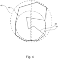
- Figure 4 schematically shows a cross section of a flow guiding element 26 of an interrupter unit 10 (not shown) according to a further preferred embodiment.
- the cross section of the flow guiding element 26 is a closed concave shape, similar to a distorted C.
- a convex hull 44 of the closed shape is also depicted in figure 4 by dashed lines.
- a minimum bounding circle 46 and a maximum inscribed circle 48 of the convex hull 44 is shown in figure 4 .
- the aspect ratio i.e. the ratio of the diameter of the minimum bounding circle 46 to the diameter of the maximum inscribed circle 48 for this flow guiding element is around 1,4:1.
- Figure 5 schematically shows in a) a portion of an interrupter unit 10 of a high or medium voltage device according to preferred embodiment of the invention, and in b) a portion of an interrupter unit 10' of a high or medium voltage device according to prior art.
- connection of the heating channel 18 to the heating volume 20 is not designed such that a sharp corner 28 is formed.
- the transition region comprises the fillet 42.
- the cross section of the flow guiding element 26 comprises a circle and the flow guiding element 26 is entirely arranged within the fillet region.
- the prior art interrupter unit 10' shown in figure 5b neither comprises a flow guiding element nor comprise a fillet. Instead, a sharp corner 28' is formed.
- the flow guiding element 26 bypasses part of the high PTFE content arc extinguishing gas entering in the heating volume 20, deflecting it towards an outer surface of the heating volume 20. Consequently, the part of the high PTFE content arc extinguishing gas traveling along the sidewall 34 closer to the switching axis 16 penetrates less into the heating volume 20 thus reducing its mixing with the arc extinguishing gas already present therein and having a low PTFE content.
- arc extinguishing gas having a high PTFE content flows into the arcing region 22 in the subsequent flow reversal phase, which in turn improves the thermal interruption performance of the interrupter unit 10.
Landscapes
- Circuit Breakers (AREA)
Abstract
Description
- The invention relates to an interrupter unit for a gas-insulated high or medium voltage device.
- Furthermore, the invention relates to a gas-insulated high or medium voltage device comprising the above interrupter unit and further an arc extinguishing gas.
- High or medium voltage devices, such as circuit breakers and switchgears are essential for the protection of technical equipment, especially in the high voltage range. For example, circuit breakers are predominantly used for interrupting a current, when an electrical fault occurs. As an example, circuit breakers have the task of opening arcing contacts, quench an arc, and keeping the arcing contacts apart from one another in order to avoid a current flow even in case of high electrical potential originating from the electrical fault itself. Circuit breakers may break medium to high short circuit currents of typically 1 kA to 80 kA at medium to high voltages of 12 kV to 72 kV and up to 1200 kV. Thus, high or medium voltage devices accommodate high-voltage conductors such as conductors to which a high voltage is applied.
- Some high or medium voltage devices, namely gas-insulated high or medium voltage devices comprise an insulation gas, for example sulphur hexafluoride, in order to shield and insulate the high-voltage conductor from other component and/or to improve quenching of an arc, when operating arcing contacts.
- In particular the insulation gas is used for extinguishing the arc generated in an arcing region between the arcing contacts when a fault current is to be interrupted and is thus also called arc extinguishing gas. The arcing region is typically surrounded by an insulating nozzle. The nozzle typically also serves for guiding a stream of the insulation gas for extinguishing, or blowing off, the arc. Thereby, the arc extinguishing gas is typically guided by a dedicated passage in the nozzle, also called heating channel, which ends close to the arcing region. Thus, the arc extinguishing gas is guided directly onto the developing arc.
- An electric arc is made up by a flux of electrons and a flux of ions which circulate in opposite directions between the arcing contacts. When the temperature of the arc decreases, ions and electrons recombine and the arc extinguishing gas resumes its electrical insulating properties. In a gas insulated circuit breaker, a cooler gaseous mantle surrounds the hot core of the arc. The temperature of the gaseous mantle decreases as the distance from the arc axis is increased. The current flow is interrupted when an efficient blast of arc extinguishing gas is applied to cool the arc and extinguish it. The capability of how efficient the arc is extinguished at the zero crossing of the alternating fault current by a high or medium voltage device is called thermal interruption performance.
- Sulphur hexafluoride (SF6) is widely used as arc extinguishing gas, as it is known for its high dielectric strength and thermal interruption capability. However, SF6 might have some environmental impact when released into the atmosphere, in particular due to its relatively high global warming potential and its relatively long lifetime in the atmosphere.
- Thus, efforts have been made to substitute SF6 with different more environmentally friendly arc extinguishing gases or to reduce the SF6 content in the arc extinguishing gas mixture. For example, one candidate for substituting SF6 as insulation gas is CO2. However, the arc extinguishing capability of CO2 is inferior to that of SF6. Thus, for a circuit breaker of a conventional design, a sufficient interruption performance is thus often not achieved when CO2 is used as a quenching gas instead of SF6. This is particularly the case for relatively high short-circuit currents and voltage ratings.
- It is an object of the invention to provide means to improve the thermal interruption performance of gas-insulated high or medium voltage devices, particularly for gas-insulated high or medium voltage devices comprising an arc extinguishing gas having a reduced SF6 content or being free of SF6.
- The object of the invention is solved by the features of the independent claims. Modified embodiments are detailed in the dependent claims.
- Thus, the object is solved by an interrupter unit for a gas-insulated high or medium voltage device comprising a first arcing contact and a second arcing contact, wherein at least one of the arcing contacts is axially movable along a switching axis, a heating channel for guiding an arc extinguishing gas from a heating volume to an arcing region formed between the first arcing contact and the second arcing contact, wherein the interrupter unit comprises in a transition region of the heating volume to the heating channel a flow guiding element, and wherein a cross section of the flow guiding element along a plane comprising the switching axis comprises a closed shape, and wherein an aspect ratio of a convex hull of the closed shape is in between 1:3 to 3:1.
- The object is also solved by a gas-insulated high or medium voltage device comprising the above interrupter unit and wherein the high or medium voltage device further comprises an arc extinguishing gas.
- Preferably the arc extinguishing gas is selected from CO2, mixtures comprising CO2, mixtures of CO2 with a carrier gas and/or mixtures of fluoroketons and/or fluoronitriles with a carrier gas. The carrier gas for use with CO2, fluoroketons and/or fluoronitriles may comprise air, N2, CO2, and mixtures thereof. Further preferably the arc extinguishing gas may have a reduced fluorine content compared to SF6 or may even be fluorine free.
- According to another preferred embodiment of the invention the gas-insulated high or medium voltage device is preferably a circuit breaker and more preferably the gas-insulated high or medium voltage device is configured as a puffer-type circuit breaker, a self-blast circuit breaker, or a combined puffer-type and self-blast circuit breaker. In the context of this invention medium to high voltages means voltages of 12 kV to 72 kV (medium voltage) and up to 1200 kV (high voltage).
- An important parameter influencing the thermal interruption capability of an interruption unit is the flow of the arc extinguishing gas in the arcing region. The arcing region is typically surrounded by a nozzle for electrical insulation purpose. The nozzle preferably also serves for guiding the arc extinguishing gas from the heating volume to the arcing region. In other words, the heating channel connecting the heating volume with the arcing region is formed by the nozzle and in particular is formed in between an auxiliary nozzle at least partially surrounding one of the arcing contacts and an insulating nozzle. As the heating channel ends close to the arcing region, the arc extinguishing gas is preferably guided directly onto the developing arc during circuit breaking.
- It has been found that a flow guiding element in the transition region from the heating volume to the heating channel, wherein the cross section of said flow guiding element along the plane comprising the switching axis comprises the closed shape, and wherein the aspect ratio of the convex hull of the closed shape is in between 1:3 to 3:1, can aid in improving the thermal interruption capabilities of the interrupter unit.
- Without being bound to a specific theory, it is believed that the increased interruption capability of the interruption unit is at least in part based on an increased polytetra-fluorethylene (PTFE) vapor concentration of the arc extinguishing gas in the arcing region in a flow reversal phase, due to a decreased mixing of the arc extinguishing gas in the heating volume during a back heating phase of current interruption:
During circuit breaking operation of the high or medium voltage device, by moving at least one of the arcing contacts along the switching axis, a direct contact between the arcing contacts is broken, such that an arc develops between the arcing contacts. In a high-current phase of the arcing period, the radiative energy of the burning arc induces PTFE evaporation at a nozzle surface surrounding the arcing region, which yields a rise of the pressure of the arc extinguishing gas in the region between the arcing contacts, for which the arc extinguishing gas expands in all available directions. In particular, the expanding arc extinguishing gas also streams from the arcing region to the heating volume, filling it at high pressure. This phase, where the arc extinguishing gas streams from the arcing region into the heating volume is called back heating phase or ablation-controlled arc phase. The described mechanism of pressure generation is typical for self-blast circuit breakers. In case of puffer-type circuit breakers, the pressure generated by the arc is further augmented by the shrinking of a compression volume. - When the fault alternating current decreases, the arc loses energy and, at some point, stops pumping mass and energy into the heating volume. The high-pressure gas stored in the heating volume consequently moves back towards the arc, thus quenching it. This phase is called flow reversal phase or axially blown arc phase.
- As already mentioned, due to the high radiative energy of the arc in the high-current phase of the arcing period, ablation of the nozzle surrounding the arcing region takes place, influencing the chemical composition of the arc extinguishing gas in the arcing region. In particular nozzle ablation may increase the content of PTFE in the arc extinguishing gas being present in the arcing region during this phase.
- It is believed that the flow guiding element in the transition region of the heating volume to the heating channel decreases the mixing of the arc extinguishing gas having a high PTFE content flowing into the heating volume with the arc extinguishing gas already present in the heating volume and having a low PTFE content in the back heating phase. As mixing in the heating volume is decreased in the back heating phase, arc extinguishing gas having a high PTFE content flows into the arcing region in the subsequent flow reversal phase, which in turn improves the thermal interruption performance of the interrupter unit.
- As already mentioned, the cross section of the flow guiding element along the plane comprising the switching axis comprises the closed shape, and wherein the aspect ratio of the convex hull of the closed shape is in between 1:3 to 3:1. The closed shape is a shape, whose boundary lines are connected and/or meet end to end. In other words, a closed shape starts and ends at the same point. In principle, the closed shape can have any form, as long as the aspect ratio of its convex hull is in between 1:3 to 3:1. For example the closed shape can have the form of an ellipse with a wavy boundary line or the form of the letter D.
- In case the closed shape is convex, the convex hull of the closed shape corresponds to the closed shape itself. In case the closed shape is concave, then the convex hull of the concave closed shape is the smallest convex shape that contains the concave closed shape.
- The aspect ratio of the convex hull is a measure for the "circlishness" of the convex hull. In the context of this invention the aspect ratio is the ratio between the diameter of the minimum bounding circle of the convex hull and the diameter of the maximum inscribed circle of the convex hull. The minimum bounding circle is the smallest circle that contains all points of the boundary line of the convex hull. The maximum inscribed circle of the convex hull is the maximum circle within the convex hull. For example, when the cross section of the flow guiding element is a circle, the aspect ratio would be 1:1.
- In other words, the form of the flow guiding element preferably corresponds to a bluff body. In contrary to a streamlined body, which offers least resistance to a stream of gas in terms of pressure drag, a bluff body is such that boundary layers may separate to form unsteady vortex flows in a wake region of the bluff body. By using a flow guiding element whose cross-section is shaped as a bluff body, the mixing of the arc extinguishing gas having a high PTFE content with the arc extinguishing gas already present in the heating volume in the back heating phase is efficiently hindered.
- According to a preferred embodiment of the invention, the closed shape is a regular polygon with at least three vertices, and preferably a regular convex polygon or a regular star polygon, or the closed shape is a circle. In other words, the cross section can comprise a regular triangle, a regular quadrangle, a regular pentagon, a regular pentagram, a regular hexagon, a regular hexagram, a regular heptagon, a regular heptagram, a regular octagon, a regular octagram, a regular nonagon, a regular nonagram, a regular decagon, a regular decagram, and so forth e.g. a regular dodecagon, a regular dodecagram, or a circle. Mathematically spoken the crosse section comprise a regular polygon with n vertices with n ≥ 3 and up to ∞, as the regular polygon with indefinite vertices corresponds to the circle.
- In this context and according to another preferred embodiment of the invention, the polygon is a regular convex polygon or a regular star polygon. A regular polygon is convex if every line that does not contain any edge of the polygon intersects the polygon in at most two points. For example, the regular pentagon or hexagon are regular convex polygons. A regular star polygon is a non-convex regular polygon, such as a pentagram or hexagram. Regular star polygons have the same vertices as their corresponding regular convex polygons, but connect alternating vertices. Preferably, the cross-section of the flow guiding element comprises the regular convex polygon with n vertices with n ≥ 3. This has the advantage that it is easier to manufacture than the star polygon. Further preferably, the cross-section of the flow guiding element comprises the circle.
- Particular preferably the flow guiding element is formed such that a flow of a back streaming arc extinguishing gas from the arcing region into the heating volume is split into at least two sub streams. Further preferably the flow guiding element is formed such that the flow of the back streaming arc extinguishing gas from the arcing region separates into at least two sub streams. Hence, mixing of the back streaming arc extinguishing gas from the arcing region with the arc extinguishing gas within the heating volume is efficiently decreased.
- As already mentioned, the flow guiding element is arranged within the transition region of the heating volume to the heating channel. The transition region is formed around the connection of the heating channel to the heating volume. The heating channel as well as the heating volume are preferably enclosed by sidewalls, wherein the heating channel extends essentially along the direction of the switching axis. At the connection of the heating channel to the heating volume the sidewalls of the heating channel and the heating volume merge. The transition region is preferably the region around the connection where a significant increase or decrease of a distance between the sidewalls enclosing the heating channel and/or the sidewalls enclosing the heating volume takes place in the course of the direction of the switching axis.
- According to a preferred embodiment of the invention, a sidewall of the heating channel and/or heating volume in the transition region comprises a fillet. Particular preferably, the sidewall of the heating channel and/or heating volume at a connection of the heating channel to the heating volume comprises the fillet. A fillet is a rounding of an interior or exterior corner. As already mentioned above, at the connection of the heating channel to the heating volume the distance between the sidewalls enclosing the heating channel and the sidewalls enclosing the heating volume changes. In case the transition region does not comprise the fillet, the distance change in an abrupt manner. However, with the fillet the connection of the of the heating channel to the heating volume is more gradual and also the distance between the opposing sidewalls changes more gradually. Preferably the flow guiding element is arranged with respect to the switching axis in the region of the fillet of the transition region. The fillet has the effect of slowing down and deflecting the arc extinguishing gas entering in the heating volume sideways. As a consequence, during the back heating phase the mixing of the arc extinguishing gas having high PTFE content with the arc extinguishing gas already present in the heating volume is even more hindered, and thus arc extinguishing gas having a high PTFE content flows back to the arcing region in the subsequent flow reversal phase, which in turn further improves the thermal interruption performance of the interrupter unit.
- According to a preferred embodiment of the invention, the interrupter unit comprises the nozzle, wherein the nozzle at least partially encloses the arcing region and wherein the nozzle comprises PTFE. As already mentioned, the arcing region is preferably surrounded by the nozzle for electrical insulation purpose. Preferably a material of the nozzle comprises PTFE. Ablation of the nozzle during current interruption vaporizes some of the PTFE and increases the content of PTFE in the arc extinguishing gas being present in the arcing region.
- According to another preferred embodiment of the invention, the the flow guiding element is at least partially revolving around the switching axis. Preferably the nozzle and thus the heating channel formed within the nozzle is rotationally symmetric around the switching axis. Hence, it is preferable to have a flow guiding element, that at least partially revolves around the switching axis. Further preferably, the flow guiding element is a circumferential flow guiding element and/or is ring shaped.
- In connection to this and according to another preferred embodiment, the flow guiding element is preferably rotationally symmetric around the switching axis. The ring-shaped flow guiding element is preferably rotationally symmetric. It has been found that the interruption performance is increased if the symmetry of the flow guiding element matches the symmetry of the nozzle and/or heating channel of the interrupter unit. It is also possible that the rotational symmetry of the flow guiding element around the switching axis is a discrete rotational symmetry, for example a three-fold rotational symmetry. In the example of the 3-fold rotational symmetry the shape of the flow guiding element would correspond to a ring made from three distinct segments that are separated by small gaps circumferentially.
- With regard to the arrangement of the flow guiding element, and as already stated the flow guiding element is arranged in the transition region of the heating volume to the heating channel. For example, the flow guiding element can be arranged in the heating volume in front of the opening into the heating channel. In this regard and according to a preferred embodiment of the invention, the flow guiding element is at least partially arranged within the heating channel and/or the flow guiding element is at least partially arranged within the heating volume.
- Different arrangement of the flow guiding element in the transition region are possible. Preferably the arrangement of the flow guiding element and a diameter of the polygon or circle of the cross section of the flow guiding element is such that a part of the flow guiding element is located within the heating channel - preferably meaning that this part of the flow guiding element is located in a region of the heating channel, where the distance between the opposing sidewalls of the heating channel is preferably constant over the extent of the flow guiding element.
- Alternatively or additionally and further preferably the arrangement of the flow guiding element and the diameter of the polygon or circle of the cross section of the flow guiding element is such that a part of the flow guiding element is located within the heating volume - preferably meaning that this part of the flow guiding element is located in a region of the heating volume, where the distance between the sidewalls of the heating volume is preferably constant over the extent of the flow guiding element.
- Further preferably the arrangement of the flow guiding element and the diameter of the polygon or circle of the cross section of the flow guiding element is such that the flow guiding element is located in the transition region, where the distance between the sidewalls of the heating channel and/or the sidewalls of the heating volume is changing over an extent of the flow guiding element, and preferably over the whole extent of the flow guiding element.
- According to another preferred embodiment of the invention, the heating channel comprises a portion that extends parallel to the switching axis and wherein the flow guiding element is at least partially arranged within said portion of the heating channel. It has been found that such an arrangement of the flow guiding element and such a configuration of the heating channel is advantageous for the interruption performance of the interrupter unit. Further preferably, said portion of the heating channel that is parallel to the switching axis preferably also has a constant distance between the opposing sidewalls of the heating channel. Also, this embodiment is most advantageous together with the fillet region in the transition region.
- With regard to the connection of the heating channel to the heating volume it is further preferred if one sidewall of the heating channel merges with one sidewall of the heating volume without forming a corner. This means in other words, that preferably a continuous sidewall is formed by one of the sidewalls of the heating channel and one of the sidewalls of the heating volume. Preferably the sidewall of the heating channel that merges with one sidewall of the heating volume without forming a corner, is the sidewall of the heating channel that is closer to the switching axis.
- According to another preferred embodiment of the invention, the flow guiding element is not entirely arranged within the heating channel. This means in other words, that the arrangement of the flow guiding element and the diameter of the polygon or circle of the cross section of the flow guiding element is preferably not such that the entire flow guiding element is located in a region of the heating channel, where the distance between the sidewalls of the heating channel is constant over the whole extent of the flow guiding element.
- According to another preferred embodiment of the invention, the flow guiding element is arranged spaced apart from opposing walls of the heating channel. With regard to the preferable arrangement of the flow guiding element partially within the heating channel it is preferred that a distance from the flow guiding element towards the opposing walls of the heating channel is the same ± 20%. In other words, the flow guiding element is located essentially on a central axis of the heating channel.
- According to another preferred embodiment a diameter of a minimum bounding circle of the convex hull is at least 10 % of the distance between opposing sidewalls of the heating channel. In case the closed shape is the circle this also means that the diameter of the circle is preferably at least 10 % of the distance between opposing sidewalls of the heating channel. For the regular convex polygon, the minimum bounding circle is the same as the circumcircle. The circumcircle (also called circumscribed circle) of a polygon is a circle that passes through all the vertices of the polygon. It has been found that the above given relationship between the distance of the opposing sidewalls of the heating channel and the minimum bounding circle of the convex hull or the diameter of the circle improves the interruption performance of the interrupter unit. Furthermore, the diameter of the minimum bounding circle of the convex hull is preferably not more than 60 % of the distance between opposing sidewalls of the heating channel. This preferably also means that the diameter of the circle is preferably not more than 60 % of the distance between opposing sidewalls of the heating channel.
- According to another preferred embodiment of the invention, the flow guiding element is attached to at least one of two opposing sidewalls of the heating channel and/or heating volume. Preferably the flow guiding element is attached by multiple spacers to at least one of the two opposing sidewalls. Further preferably the flow guiding element is attached by multiple spacers to the sidewall of the heating channel and/or heating volume closer to the switching axis. Further preferably, the spacers are arranged rotationally symmetric around the switching axis for attachment of the flow guiding element. This improves the flow of the arc extinguishing gas through the heating channel compared to a non-symmetrical arrangement of the spacers.
- These and other aspects of the invention will be apparent from and elucidated with reference to the embodiments described hereinafter.
- In the drawings:
- Fig. 1
- schematically shows an interrupter unit of a high or medium voltage device according to a preferred embodiment of the invention,
- Fig. 2
- schematically shows a portion of an interrupter unit of a high or medium voltage device according to another preferred embodiment of the invention,
- Fig. 3
- schematically shows a portion of an interrupter unit of a high or medium voltage device according to a further preferred embodiment of the invention,
- Fig. 4
- schematically shows a cross section of a flow guiding element of an interrupter unit, according to a further preferred embodiment of the invention, and
- Fig. 5
- schematically shows in a) a portion of an interrupter unit of a high or medium voltage device according to preferred embodiment of the invention, and in b) a portion of an interrupter unit of a high or medium voltage device according to prior art.
-
Fig. 1 schematically shows aninterrupter unit 10 for a gas-insulated high or medium voltage device, according to a preferred embodiment. Theinterrupter unit 10 comprises afirst arcing contact 12 and asecond arcing contact 14. In this embodiment thefirst arcing contact 12 has the form of aplug contact 12 and thesecond arcing contact 14 is configured astulip contact 14. Theplug contact 12 is axially movable along a switchingaxis 16. Thetulip contact 14 is also axially movable along the switchingaxis 16 and is further configured to engage around a proximal portion of theplug contact 12, in the closed position of thecontacts 12, 14 (not shown infigure 1 ). Theinterrupter unit 10 further comprises aheating channel 18 for guiding an arc extinguishing gas from aheating volume 20 to an arcing region 22 formed between thefirst arcing contact 12 and thesecond arcing contact 14. - Furthermore, as can be seen in
figure 1 , theinterrupter unit 10 comprises in atransition region 24 of theheating volume 20 to the heating channel 18 aflow guiding element 26. With regard to the form of theflow guiding element 26, and as can be seen infigure 1 , a cross section of theflow guiding element 26 along a plane comprising the switchingaxis 16, comprises a circle. - Furthermore, in this embodiment the
flow guiding element 26 has a ring-shaped form and is rotationally symmetric around the switchingaxis 16. As can also be seen, theflow guiding element 26 is partially arranged within theheating channel 18 and also partially arranged within theheating volume 20. In this embodiment the connection of theheating channel 18 to theheating volume 20 is designed such that asharp corner 28 is formed at the connection. Furthermore, theflow guiding element 26 is spaced apart from two opposingsidewalls heating channel 18. - With regard to the
sidewalls figure 1 that in this embodiment thesidewall 32 closer to the switchingaxis 16 extends parallel to the switchingaxis 16 and forms a continuous wall with asidewall 34 of theheating volume 20. - The
heating channel 18 is formed by a nozzle system 36 of theinterrupter unit 10 and in particular by an insulating nozzle 38 and an auxiliary nozzle 40. The nozzle system 36 comprises PTFE for insulation purpose. -
Figure 2 schematically shows a portion of aninterrupter unit 10 of a high or medium voltage device, according to another preferred embodiment of the invention. Theinterrupter unit 10 of this embodiment is similar to theinterrupter unit 10 of the embodiment infigure 1 , hence in the following only the differences are described:
In the embodiment shown infigure 2 , the connection of theheating channel 18 to theheating volume 20 is not designed such that asharp corner 28 is formed. Instead, afillet 42 is formed at the connection. Furthermore, theflow guiding element 26 is partially arranged within theheating channel 18 and also partially arranged within the region of thefillet 42. -
Figure 3 schematically shows a portion of aninterrupter unit 10 of a high or medium voltage device, according to another preferred embodiment of the invention. Theinterrupter unit 10 of this embodiment is also similar to theinterrupter unit 10 of the embodiment infigure 1 , hence in the following only the differences are described:
In the embodiment shown infigure 3 , the connection of theheating channel 18 to theheating volume 20 is not designed such that asharp corner 28 is formed. Instead, and similar to the embodiment shown infigure 2 , the transition region comprises thefillet 42. Furthermore, the cross section of theflow guiding element 26 is not a circle, but a regular convex polygon. In this case the polygon is a heptagon. Furthermore, theflow guiding element 26 is entirely arranged within the fillet region. -
Figure 4 schematically shows a cross section of aflow guiding element 26 of an interrupter unit 10 (not shown) according to a further preferred embodiment. In this embodiment the cross section of theflow guiding element 26 is a closed concave shape, similar to a distorted C. Aconvex hull 44 of the closed shape is also depicted infigure 4 by dashed lines. Furthermore, also aminimum bounding circle 46 and a maximum inscribedcircle 48 of theconvex hull 44 is shown infigure 4 . As can be seen, the aspect ratio, i.e. the ratio of the diameter of theminimum bounding circle 46 to the diameter of the maximum inscribedcircle 48 for this flow guiding element is around 1,4:1. -
Figure 5 schematically shows in a) a portion of aninterrupter unit 10 of a high or medium voltage device according to preferred embodiment of the invention, and in b) a portion of an interrupter unit 10' of a high or medium voltage device according to prior art. - In the embodiment shown in
figure 5a ), the connection of theheating channel 18 to theheating volume 20 is not designed such that asharp corner 28 is formed. Instead, the transition region comprises thefillet 42. Furthermore, the cross section of theflow guiding element 26 comprises a circle and theflow guiding element 26 is entirely arranged within the fillet region. - The prior art interrupter unit 10' shown in
figure 5b ) neither comprises a flow guiding element nor comprise a fillet. Instead, a sharp corner 28' is formed. - With reference to
figure 5 the effect of theflow guiding element 26 is described. During the opening operation of theinterrupter unit 10, a distance between theplug contact 12 andtulip contact 14 increases an and arc forms between the arcingcontacts contacts contacts heating volume 20. This phase, where the arc extinguishing gas streams from the arcing region 22 into theheating volume 20 is called back heating phase and shown infigure 5 . - As already mentioned, due to the ablation of the nozzle system 36 in the high current phase, during the back heating phase arc extinguishing gas having a high PTFE content, which is indicated in
figure 5 with the dotted region, flows to theheating volume 20, where arc extinguishing gas is present having a low PTFE content, as indicated infigure 5 with the hatched region. - As is schematically illustrated in
figure 5 , theflow guiding element 26 bypasses part of the high PTFE content arc extinguishing gas entering in theheating volume 20, deflecting it towards an outer surface of theheating volume 20. Consequently, the part of the high PTFE content arc extinguishing gas traveling along thesidewall 34 closer to the switchingaxis 16 penetrates less into theheating volume 20 thus reducing its mixing with the arc extinguishing gas already present therein and having a low PTFE content. As mixing in theheating volume 20 is decreased in the back heating phase, arc extinguishing gas having a high PTFE content flows into the arcing region 22 in the subsequent flow reversal phase, which in turn improves the thermal interruption performance of theinterrupter unit 10. - While the invention has been illustrated and described in detail in the drawings and foregoing description, such illustration and description are to be considered illustrative or exemplary and not restrictive; the invention is not limited to the disclosed embodiments. Other variations to the disclosed embodiments can be understood and effected by those skilled in the art in practicing the claimed invention, from a study of the drawings, the disclosed, and the appended claims. In the claims, the word "comprising" does not exclude other elements or steps, and the indefinite article "a" or "an" does not exclude a plurality. The mere fact that certain measures are recited in mutually different dependent claims does not indicate that a combination of these measures cannot be used to advantage. Any reference signs in the claims should not be construed as limiting scope.
-
- 10
- interrupter unit
- 12
- first arcing contact, plug contact
- 14
- second arcing contact, tulip contact
- 16
- switching axis
- 18
- heating channel
- 20
- heating volume
- 22
- arcing region
- 24
- transition region
- 26
- flow guiding element
- 28
- sharp corner
- 30
- sidewall of heating channel
- 32
- sidewall of heating channel
- 34
- sidewall of heating volume
- 36
- nozzle system
- 38
- insulating nozzle
- 40
- auxiliary nozzle
- 42
- fillet
- 44
- convex hull
- 46
- minimum bounding circle
- 48
- maximum inscribed circle
- dotted region
- high PTFE content
- hatched region
- low PTFE content
- 10'
- interrupter unit (prior art)
- 18'
- heating channel (prior art)
- 20'
- heating volume (prior art)
- 28'
- sharp corner (prior art)
Claims (15)
- Interrupter unit (10) for a gas-insulated high or medium voltage device comprisinga first arcing contact (12) and a second arcing contact (14), wherein at least one of the arcing contacts (12,14) is axially movable along a switching axis (16),a heating channel (18) for guiding an arc extinguishing gas from a heating volume (20) to an arcing region (22) formed between the first arcing contact (12) and the second arcing contact (14),wherein the interrupter unit (10) comprises in a transition region (24) of the heating volume (20) to the heating channel (18) a flow guiding element (26),wherein a cross section of the flow guiding element (26) along a plane comprising the switching axis (16) comprises a closed shape, and wherein an aspect ratio of a convex hull (44) of the closed shape is in between 1:3 to 3:1.
- The interrupter unit (10) according to the previous claim, wherein the closed shape is a regular polygon with at least three vertices, and preferably a regular convex polygon or a regular star polygon, or wherein the closed shape is a circle.
- The interrupter unit (10) according to any of the previous claims, wherein a sidewall (30) of the heating channel (18) and/or heating volume (20) in the transition region (24) comprises a fillet (42).
- The interrupter unit (10) according to any of the previous claims, wherein the interrupter unit (10) comprises a nozzle (36, 38, 40), wherein the nozzle (36, 38, 40) at least partially encloses the arcing region (22) and wherein the nozzle (36, 38, 40) comprises PTFE.
- The interrupter unit (10) according to any of the previous claims, wherein the flow guiding element (26) is at least partially revolving around the switching axis (16).
- The interrupter unit (10) according to any of the previous claims, wherein the flow guiding element (26) is rotationally symmetric around the switching axis (16).
- The interrupter unit (10) according to any of the previous claims, wherein the flow guiding element (26) is at least partially arranged within the heating channel (18) and/or wherein the flow guiding element (26) is at least partially arranged within the heating volume (20).
- The interrupter unit (10) according to any of the previous claims, wherein the heating channel (18) comprises a portion that extends parallel to the switching axis (16) and wherein the flow guiding element (26) is at least partially arranged within said portion of the heating channel (18).
- The interrupter unit (10) according to any of the previous claims, wherein the flow guiding element (26) is not entirely arranged within the heating channel (18).
- The interrupter unit (10) according to any of the previous claims, wherein the flow guiding element (26) is arranged spaced apart from opposing walls (30, 32) of the heating channel (18).
- The interrupter unit (10) according to any of the previous claims, wherein a diameter of a minimum bounding circle of the convex hull (44) is at least 10 % of a distance between opposing sidewalls (30, 32) of the heating channel (18).
- The interrupter unit (10) according to any of the previous claims, wherein the flow guiding element (26) is attached to at least one of two opposing sidewalls (30, 32, 34) of the heating channel (18) and/or heating volume (20).
- Gas-insulated high or medium voltage device comprising an interrupter unit (10) according to any of the previous interrupter unit claims, and wherein the high or medium voltage device comprises an arc extinguishing gas.
- Gas insulated high or medium voltage device according to the previous claim, wherein the arc extinguishing gas is selected from CO2, mixtures comprising CO2, mixtures of CO2 with a carrier gas and/or mixtures of fluoroketons and/or fluoronitriles with a carrier gas.
- Gas-insulated high or medium voltage device according to any of the previous gas-insulated high or medium voltage device claim, wherein the gas-insulated high or medium voltage device is configured as a circuit breaker and more preferably as a puffer-type circuit breaker, a self-blast circuit breaker, or a combined puffer-type and self-blast circuit breaker.
Priority Applications (2)
| Application Number | Priority Date | Filing Date | Title |
|---|---|---|---|
| EP22212641.9A EP4383306B1 (en) | 2022-12-09 | 2022-12-09 | Interrupter unit for gas-insulated high or medium voltage device |
| PCT/EP2023/084867 WO2024121374A1 (en) | 2022-12-09 | 2023-12-08 | Interrupter unit for gas-insulated high or medium voltage device |
Applications Claiming Priority (1)
| Application Number | Priority Date | Filing Date | Title |
|---|---|---|---|
| EP22212641.9A EP4383306B1 (en) | 2022-12-09 | 2022-12-09 | Interrupter unit for gas-insulated high or medium voltage device |
Publications (2)
| Publication Number | Publication Date |
|---|---|
| EP4383306A1 true EP4383306A1 (en) | 2024-06-12 |
| EP4383306B1 EP4383306B1 (en) | 2025-08-13 |
Family
ID=84487509
Family Applications (1)
| Application Number | Title | Priority Date | Filing Date |
|---|---|---|---|
| EP22212641.9A Active EP4383306B1 (en) | 2022-12-09 | 2022-12-09 | Interrupter unit for gas-insulated high or medium voltage device |
Country Status (2)
| Country | Link |
|---|---|
| EP (1) | EP4383306B1 (en) |
| WO (1) | WO2024121374A1 (en) |
Citations (2)
| Publication number | Priority date | Publication date | Assignee | Title |
|---|---|---|---|---|
| DE2326650A1 (en) * | 1973-05-10 | 1974-11-21 | Bbc Brown Boveri & Cie | PRESSURE GAS SWITCH |
| DE102016105539A1 (en) * | 2016-03-24 | 2017-09-28 | Abb Schweiz Ag | Electrical power switching device |
-
2022
- 2022-12-09 EP EP22212641.9A patent/EP4383306B1/en active Active
-
2023
- 2023-12-08 WO PCT/EP2023/084867 patent/WO2024121374A1/en not_active Ceased
Patent Citations (2)
| Publication number | Priority date | Publication date | Assignee | Title |
|---|---|---|---|---|
| DE2326650A1 (en) * | 1973-05-10 | 1974-11-21 | Bbc Brown Boveri & Cie | PRESSURE GAS SWITCH |
| DE102016105539A1 (en) * | 2016-03-24 | 2017-09-28 | Abb Schweiz Ag | Electrical power switching device |
Also Published As
| Publication number | Publication date |
|---|---|
| WO2024121374A1 (en) | 2024-06-13 |
| EP4383306B1 (en) | 2025-08-13 |
Similar Documents
| Publication | Publication Date | Title |
|---|---|---|
| US5057655A (en) | Electrical circuit breaker with self-extinguishing expansion and insulating gas | |
| US20080314873A1 (en) | Switching chamber for a high-voltage switch having a heating volume for holding quenching gas produced by switching arcs | |
| US11699559B2 (en) | Device for interrupting non-short circuit currents only, in particular disconnector or earthing switch | |
| RU2738087C2 (en) | Gas isolated low or medium voltage load breaker | |
| CN110088868B (en) | Electrical switching device | |
| WO2013153110A1 (en) | Circuit breaker | |
| CN110770868B (en) | Gas-insulated load break switch and switchgear comprising a gas-insulated load break switch | |
| AU638851B2 (en) | Puffer type gas-insulated circuit breaker | |
| EP4383306B1 (en) | Interrupter unit for gas-insulated high or medium voltage device | |
| JPH08321233A (en) | Circuit breaker | |
| EP4246548A1 (en) | Interrupter unit for gas-insulated high or medium voltage device and gas-insulated high or medium voltage device | |
| US20080135523A1 (en) | Self-blast circuit breaker with control body | |
| EP3590120B1 (en) | High-voltage circuit breaker with improved robustness | |
| CN111630622A (en) | Gas-insulated high or medium voltage circuit breakers | |
| WO2019121732A1 (en) | Circuit breaker and method of performing a current breaking operation | |
| EP4362054A1 (en) | Method for determining a control signal of an electromagnetic drive of an interrupter unit, and interrupter unit for a gas-insulated high or medium voltage device | |
| EP4738416A1 (en) | Circuit-breaker | |
| EP2827353A1 (en) | Electrical switching device | |
| EP4117006B1 (en) | Gas-insulated high or medium voltage circuit breaker | |
| RU2148281C1 (en) | Arc-control device of self-compression gas-filled high-voltage switch | |
| EP4235723A1 (en) | Three-phase gas-insulated circuit breaker | |
| KR101621765B1 (en) | Switch-gear | |
| JP2523478B2 (en) | Puffer type gas breaker | |
| RU2396629C2 (en) | Arc-extinguishing device of high-voltage gas-filled puffer breaker | |
| WO2025022682A1 (en) | Gas circuit breaker |
Legal Events
| Date | Code | Title | Description |
|---|---|---|---|
| PUAI | Public reference made under article 153(3) epc to a published international application that has entered the european phase |
Free format text: ORIGINAL CODE: 0009012 |
|
| STAA | Information on the status of an ep patent application or granted ep patent |
Free format text: STATUS: THE APPLICATION HAS BEEN PUBLISHED |
|
| AK | Designated contracting states |
Kind code of ref document: A1 Designated state(s): AL AT BE BG CH CY CZ DE DK EE ES FI FR GB GR HR HU IE IS IT LI LT LU LV MC ME MK MT NL NO PL PT RO RS SE SI SK SM TR |
|
| STAA | Information on the status of an ep patent application or granted ep patent |
Free format text: STATUS: REQUEST FOR EXAMINATION WAS MADE |
|
| 17P | Request for examination filed |
Effective date: 20241212 |
|
| GRAP | Despatch of communication of intention to grant a patent |
Free format text: ORIGINAL CODE: EPIDOSNIGR1 |
|
| STAA | Information on the status of an ep patent application or granted ep patent |
Free format text: STATUS: GRANT OF PATENT IS INTENDED |
|
| RIC1 | Information provided on ipc code assigned before grant |
Ipc: H01H 9/30 20060101ALN20250210BHEP Ipc: H01H 33/56 20060101ALN20250210BHEP Ipc: H01H 33/70 20060101ALN20250210BHEP Ipc: H01H 33/98 20060101ALI20250210BHEP Ipc: H01H 33/74 20060101AFI20250210BHEP |
|
| INTG | Intention to grant announced |
Effective date: 20250304 |
|
| P01 | Opt-out of the competence of the unified patent court (upc) registered |
Free format text: CASE NUMBER: APP_25496/2025 Effective date: 20250528 |
|
| GRAS | Grant fee paid |
Free format text: ORIGINAL CODE: EPIDOSNIGR3 |
|
| GRAA | (expected) grant |
Free format text: ORIGINAL CODE: 0009210 |
|
| STAA | Information on the status of an ep patent application or granted ep patent |
Free format text: STATUS: THE PATENT HAS BEEN GRANTED |
|
| AK | Designated contracting states |
Kind code of ref document: B1 Designated state(s): AL AT BE BG CH CY CZ DE DK EE ES FI FR GB GR HR HU IE IS IT LI LT LU LV MC ME MK MT NL NO PL PT RO RS SE SI SK SM TR |
|
| REG | Reference to a national code |
Ref country code: GB Ref legal event code: FG4D |
|
| REG | Reference to a national code |
Ref country code: CH Ref legal event code: EP |
|
| REG | Reference to a national code |
Ref country code: DE Ref legal event code: R096 Ref document number: 602022019340 Country of ref document: DE |
|
| REG | Reference to a national code |
Ref country code: IE Ref legal event code: FG4D |
|
| REG | Reference to a national code |
Ref country code: NL Ref legal event code: MP Effective date: 20250813 |
|
| REG | Reference to a national code |
Ref country code: CH Ref legal event code: U11 Free format text: ST27 STATUS EVENT CODE: U-0-0-U10-U11 (AS PROVIDED BY THE NATIONAL OFFICE) Effective date: 20260101 |
|
| PG25 | Lapsed in a contracting state [announced via postgrant information from national office to epo] |
Ref country code: IS Free format text: LAPSE BECAUSE OF FAILURE TO SUBMIT A TRANSLATION OF THE DESCRIPTION OR TO PAY THE FEE WITHIN THE PRESCRIBED TIME-LIMIT Effective date: 20251213 |
|
| PGFP | Annual fee paid to national office [announced via postgrant information from national office to epo] |
Ref country code: DE Payment date: 20251211 Year of fee payment: 4 |
|
| PG25 | Lapsed in a contracting state [announced via postgrant information from national office to epo] |
Ref country code: NO Free format text: LAPSE BECAUSE OF FAILURE TO SUBMIT A TRANSLATION OF THE DESCRIPTION OR TO PAY THE FEE WITHIN THE PRESCRIBED TIME-LIMIT Effective date: 20251113 |
|
| REG | Reference to a national code |
Ref country code: LT Ref legal event code: MG9D |
|
| PG25 | Lapsed in a contracting state [announced via postgrant information from national office to epo] |
Ref country code: PT Free format text: LAPSE BECAUSE OF FAILURE TO SUBMIT A TRANSLATION OF THE DESCRIPTION OR TO PAY THE FEE WITHIN THE PRESCRIBED TIME-LIMIT Effective date: 20251215 |
|
| PG25 | Lapsed in a contracting state [announced via postgrant information from national office to epo] |
Ref country code: FI Free format text: LAPSE BECAUSE OF FAILURE TO SUBMIT A TRANSLATION OF THE DESCRIPTION OR TO PAY THE FEE WITHIN THE PRESCRIBED TIME-LIMIT Effective date: 20250813 |
|
| PG25 | Lapsed in a contracting state [announced via postgrant information from national office to epo] |
Ref country code: NL Free format text: LAPSE BECAUSE OF FAILURE TO SUBMIT A TRANSLATION OF THE DESCRIPTION OR TO PAY THE FEE WITHIN THE PRESCRIBED TIME-LIMIT Effective date: 20250813 Ref country code: HR Free format text: LAPSE BECAUSE OF FAILURE TO SUBMIT A TRANSLATION OF THE DESCRIPTION OR TO PAY THE FEE WITHIN THE PRESCRIBED TIME-LIMIT Effective date: 20250813 |
|
| PGFP | Annual fee paid to national office [announced via postgrant information from national office to epo] |
Ref country code: FR Payment date: 20251229 Year of fee payment: 4 |
|
| PG25 | Lapsed in a contracting state [announced via postgrant information from national office to epo] |
Ref country code: GR Free format text: LAPSE BECAUSE OF FAILURE TO SUBMIT A TRANSLATION OF THE DESCRIPTION OR TO PAY THE FEE WITHIN THE PRESCRIBED TIME-LIMIT Effective date: 20251114 |
|
| PG25 | Lapsed in a contracting state [announced via postgrant information from national office to epo] |
Ref country code: SE Free format text: LAPSE BECAUSE OF FAILURE TO SUBMIT A TRANSLATION OF THE DESCRIPTION OR TO PAY THE FEE WITHIN THE PRESCRIBED TIME-LIMIT Effective date: 20250813 |
|
| PG25 | Lapsed in a contracting state [announced via postgrant information from national office to epo] |
Ref country code: LV Free format text: LAPSE BECAUSE OF FAILURE TO SUBMIT A TRANSLATION OF THE DESCRIPTION OR TO PAY THE FEE WITHIN THE PRESCRIBED TIME-LIMIT Effective date: 20250813 |
|
| PG25 | Lapsed in a contracting state [announced via postgrant information from national office to epo] |
Ref country code: PL Free format text: LAPSE BECAUSE OF FAILURE TO SUBMIT A TRANSLATION OF THE DESCRIPTION OR TO PAY THE FEE WITHIN THE PRESCRIBED TIME-LIMIT Effective date: 20250813 Ref country code: BG Free format text: LAPSE BECAUSE OF FAILURE TO SUBMIT A TRANSLATION OF THE DESCRIPTION OR TO PAY THE FEE WITHIN THE PRESCRIBED TIME-LIMIT Effective date: 20250813 |
|
| PG25 | Lapsed in a contracting state [announced via postgrant information from national office to epo] |
Ref country code: RS Free format text: LAPSE BECAUSE OF FAILURE TO SUBMIT A TRANSLATION OF THE DESCRIPTION OR TO PAY THE FEE WITHIN THE PRESCRIBED TIME-LIMIT Effective date: 20251113 |
|
| PG25 | Lapsed in a contracting state [announced via postgrant information from national office to epo] |
Ref country code: ES Free format text: LAPSE BECAUSE OF FAILURE TO SUBMIT A TRANSLATION OF THE DESCRIPTION OR TO PAY THE FEE WITHIN THE PRESCRIBED TIME-LIMIT Effective date: 20250813 |
|
| REG | Reference to a national code |
Ref country code: AT Ref legal event code: MK05 Ref document number: 1825667 Country of ref document: AT Kind code of ref document: T Effective date: 20250813 |
|
| PG25 | Lapsed in a contracting state [announced via postgrant information from national office to epo] |
Ref country code: RO Free format text: LAPSE BECAUSE OF FAILURE TO SUBMIT A TRANSLATION OF THE DESCRIPTION OR TO PAY THE FEE WITHIN THE PRESCRIBED TIME-LIMIT Effective date: 20250813 |
|
| PG25 | Lapsed in a contracting state [announced via postgrant information from national office to epo] |
Ref country code: SM Free format text: LAPSE BECAUSE OF FAILURE TO SUBMIT A TRANSLATION OF THE DESCRIPTION OR TO PAY THE FEE WITHIN THE PRESCRIBED TIME-LIMIT Effective date: 20250813 |
|
| PG25 | Lapsed in a contracting state [announced via postgrant information from national office to epo] |
Ref country code: DK Free format text: LAPSE BECAUSE OF FAILURE TO SUBMIT A TRANSLATION OF THE DESCRIPTION OR TO PAY THE FEE WITHIN THE PRESCRIBED TIME-LIMIT Effective date: 20250813 |
|
| PG25 | Lapsed in a contracting state [announced via postgrant information from national office to epo] |
Ref country code: AT Free format text: LAPSE BECAUSE OF FAILURE TO SUBMIT A TRANSLATION OF THE DESCRIPTION OR TO PAY THE FEE WITHIN THE PRESCRIBED TIME-LIMIT Effective date: 20250813 |
|
| PG25 | Lapsed in a contracting state [announced via postgrant information from national office to epo] |
Ref country code: IT Free format text: LAPSE BECAUSE OF FAILURE TO SUBMIT A TRANSLATION OF THE DESCRIPTION OR TO PAY THE FEE WITHIN THE PRESCRIBED TIME-LIMIT Effective date: 20250813 |
|
| PG25 | Lapsed in a contracting state [announced via postgrant information from national office to epo] |
Ref country code: CZ Free format text: LAPSE BECAUSE OF FAILURE TO SUBMIT A TRANSLATION OF THE DESCRIPTION OR TO PAY THE FEE WITHIN THE PRESCRIBED TIME-LIMIT Effective date: 20250813 |
|
| PGFP | Annual fee paid to national office [announced via postgrant information from national office to epo] |
Ref country code: CH Payment date: 20260101 Year of fee payment: 4 |
|
| PG25 | Lapsed in a contracting state [announced via postgrant information from national office to epo] |
Ref country code: EE Free format text: LAPSE BECAUSE OF FAILURE TO SUBMIT A TRANSLATION OF THE DESCRIPTION OR TO PAY THE FEE WITHIN THE PRESCRIBED TIME-LIMIT Effective date: 20250813 Ref country code: SK Free format text: LAPSE BECAUSE OF FAILURE TO SUBMIT A TRANSLATION OF THE DESCRIPTION OR TO PAY THE FEE WITHIN THE PRESCRIBED TIME-LIMIT Effective date: 20250813 |