EP4383231A1 - Display device for vehicle - Google Patents
Display device for vehicle Download PDFInfo
- Publication number
- EP4383231A1 EP4383231A1 EP22852866.7A EP22852866A EP4383231A1 EP 4383231 A1 EP4383231 A1 EP 4383231A1 EP 22852866 A EP22852866 A EP 22852866A EP 4383231 A1 EP4383231 A1 EP 4383231A1
- Authority
- EP
- European Patent Office
- Prior art keywords
- notification pattern
- vehicle
- projection
- projected
- pattern
- Prior art date
- Legal status (The legal status is an assumption and is not a legal conclusion. Google has not performed a legal analysis and makes no representation as to the accuracy of the status listed.)
- Granted
Links
Images





Classifications
-
- B—PERFORMING OPERATIONS; TRANSPORTING
- B60—VEHICLES IN GENERAL
- B60Q—ARRANGEMENT OF SIGNALLING OR LIGHTING DEVICES, THE MOUNTING OR SUPPORTING THEREOF OR CIRCUITS THEREFOR, FOR VEHICLES IN GENERAL
- B60Q1/00—Arrangement of optical signalling or lighting devices, the mounting or supporting thereof or circuits therefor
- B60Q1/26—Arrangement of optical signalling or lighting devices, the mounting or supporting thereof or circuits therefor the devices being primarily intended to indicate the vehicle, or parts thereof, or to give signals, to other traffic
- B60Q1/50—Arrangement of optical signalling or lighting devices, the mounting or supporting thereof or circuits therefor the devices being primarily intended to indicate the vehicle, or parts thereof, or to give signals, to other traffic for indicating other intentions or conditions, e.g. request for waiting or overtaking
-
- G—PHYSICS
- G08—SIGNALLING
- G08G—TRAFFIC CONTROL SYSTEMS
- G08G1/00—Traffic control systems for road vehicles
- G08G1/16—Anti-collision systems
-
- B—PERFORMING OPERATIONS; TRANSPORTING
- B60—VEHICLES IN GENERAL
- B60Q—ARRANGEMENT OF SIGNALLING OR LIGHTING DEVICES, THE MOUNTING OR SUPPORTING THEREOF OR CIRCUITS THEREFOR, FOR VEHICLES IN GENERAL
- B60Q1/00—Arrangement of optical signalling or lighting devices, the mounting or supporting thereof or circuits therefor
- B60Q1/02—Arrangement of optical signalling or lighting devices, the mounting or supporting thereof or circuits therefor the devices being primarily intended to illuminate the way ahead or to illuminate other areas of way or environments
- B60Q1/22—Arrangement of optical signalling or lighting devices, the mounting or supporting thereof or circuits therefor the devices being primarily intended to illuminate the way ahead or to illuminate other areas of way or environments for reverse drive
-
- B—PERFORMING OPERATIONS; TRANSPORTING
- B60—VEHICLES IN GENERAL
- B60Q—ARRANGEMENT OF SIGNALLING OR LIGHTING DEVICES, THE MOUNTING OR SUPPORTING THEREOF OR CIRCUITS THEREFOR, FOR VEHICLES IN GENERAL
- B60Q1/00—Arrangement of optical signalling or lighting devices, the mounting or supporting thereof or circuits therefor
- B60Q1/26—Arrangement of optical signalling or lighting devices, the mounting or supporting thereof or circuits therefor the devices being primarily intended to indicate the vehicle, or parts thereof, or to give signals, to other traffic
- B60Q1/34—Arrangement of optical signalling or lighting devices, the mounting or supporting thereof or circuits therefor the devices being primarily intended to indicate the vehicle, or parts thereof, or to give signals, to other traffic for indicating change of drive direction
-
- B—PERFORMING OPERATIONS; TRANSPORTING
- B60—VEHICLES IN GENERAL
- B60Q—ARRANGEMENT OF SIGNALLING OR LIGHTING DEVICES, THE MOUNTING OR SUPPORTING THEREOF OR CIRCUITS THEREFOR, FOR VEHICLES IN GENERAL
- B60Q1/00—Arrangement of optical signalling or lighting devices, the mounting or supporting thereof or circuits therefor
- B60Q1/26—Arrangement of optical signalling or lighting devices, the mounting or supporting thereof or circuits therefor the devices being primarily intended to indicate the vehicle, or parts thereof, or to give signals, to other traffic
- B60Q1/50—Arrangement of optical signalling or lighting devices, the mounting or supporting thereof or circuits therefor the devices being primarily intended to indicate the vehicle, or parts thereof, or to give signals, to other traffic for indicating other intentions or conditions, e.g. request for waiting or overtaking
- B60Q1/525—Arrangement of optical signalling or lighting devices, the mounting or supporting thereof or circuits therefor the devices being primarily intended to indicate the vehicle, or parts thereof, or to give signals, to other traffic for indicating other intentions or conditions, e.g. request for waiting or overtaking automatically indicating risk of collision between vehicles in traffic or with pedestrians, e.g. after risk assessment using the vehicle sensor data
-
- B—PERFORMING OPERATIONS; TRANSPORTING
- B60—VEHICLES IN GENERAL
- B60Q—ARRANGEMENT OF SIGNALLING OR LIGHTING DEVICES, THE MOUNTING OR SUPPORTING THEREOF OR CIRCUITS THEREFOR, FOR VEHICLES IN GENERAL
- B60Q1/00—Arrangement of optical signalling or lighting devices, the mounting or supporting thereof or circuits therefor
- B60Q1/26—Arrangement of optical signalling or lighting devices, the mounting or supporting thereof or circuits therefor the devices being primarily intended to indicate the vehicle, or parts thereof, or to give signals, to other traffic
- B60Q1/50—Arrangement of optical signalling or lighting devices, the mounting or supporting thereof or circuits therefor the devices being primarily intended to indicate the vehicle, or parts thereof, or to give signals, to other traffic for indicating other intentions or conditions, e.g. request for waiting or overtaking
- B60Q1/543—Arrangement of optical signalling or lighting devices, the mounting or supporting thereof or circuits therefor the devices being primarily intended to indicate the vehicle, or parts thereof, or to give signals, to other traffic for indicating other intentions or conditions, e.g. request for waiting or overtaking for indicating other states or conditions of the vehicle
-
- B—PERFORMING OPERATIONS; TRANSPORTING
- B60—VEHICLES IN GENERAL
- B60Q—ARRANGEMENT OF SIGNALLING OR LIGHTING DEVICES, THE MOUNTING OR SUPPORTING THEREOF OR CIRCUITS THEREFOR, FOR VEHICLES IN GENERAL
- B60Q9/00—Arrangement or adaptation of signal devices not provided for in one of main groups B60Q1/00 - B60Q7/00, e.g. haptic signalling
- B60Q9/008—Arrangement or adaptation of signal devices not provided for in one of main groups B60Q1/00 - B60Q7/00, e.g. haptic signalling for anti-collision purposes
-
- B—PERFORMING OPERATIONS; TRANSPORTING
- B60—VEHICLES IN GENERAL
- B60R—VEHICLES, VEHICLE FITTINGS, OR VEHICLE PARTS, NOT OTHERWISE PROVIDED FOR
- B60R1/00—Optical viewing arrangements; Real-time viewing arrangements for drivers or passengers using optical image capturing systems, e.g. cameras or video systems specially adapted for use in or on vehicles
- B60R1/20—Real-time viewing arrangements for drivers or passengers using optical image capturing systems, e.g. cameras or video systems specially adapted for use in or on vehicles
- B60R1/22—Real-time viewing arrangements for drivers or passengers using optical image capturing systems, e.g. cameras or video systems specially adapted for use in or on vehicles for viewing an area outside the vehicle, e.g. the exterior of the vehicle
-
- B—PERFORMING OPERATIONS; TRANSPORTING
- B60—VEHICLES IN GENERAL
- B60R—VEHICLES, VEHICLE FITTINGS, OR VEHICLE PARTS, NOT OTHERWISE PROVIDED FOR
- B60R11/00—Arrangements for holding or mounting articles, not otherwise provided for
- B60R11/04—Mounting of cameras operative during drive; Arrangement of controls thereof relative to the vehicle
-
- F—MECHANICAL ENGINEERING; LIGHTING; HEATING; WEAPONS; BLASTING
- F21—LIGHTING
- F21S—NON-PORTABLE LIGHTING DEVICES; SYSTEMS THEREOF; VEHICLE LIGHTING DEVICES SPECIALLY ADAPTED FOR VEHICLE EXTERIORS
- F21S43/00—Signalling devices specially adapted for vehicle exteriors, e.g. brake lamps, direction indicator lights or reversing lights
- F21S43/20—Signalling devices specially adapted for vehicle exteriors, e.g. brake lamps, direction indicator lights or reversing lights characterised by refractors, transparent cover plates, light guides or filters
- F21S43/2605—Refractors
- F21S43/2621—Refractors characterised by the properties of the light beam shaping surface
- F21S43/26231—Refractors characterised by the properties of the light beam shaping surface collimating, focusing, condensing or projecting beams, e.g. projection lenses or Fresnel lenses
-
- F—MECHANICAL ENGINEERING; LIGHTING; HEATING; WEAPONS; BLASTING
- F21—LIGHTING
- F21S—NON-PORTABLE LIGHTING DEVICES; SYSTEMS THEREOF; VEHICLE LIGHTING DEVICES SPECIALLY ADAPTED FOR VEHICLE EXTERIORS
- F21S43/00—Signalling devices specially adapted for vehicle exteriors, e.g. brake lamps, direction indicator lights or reversing lights
- F21S43/601—Signalling devices specially adapted for vehicle exteriors, e.g. brake lamps, direction indicator lights or reversing lights characterised by variable optical properties, e.g. involving the use of LCD or movable parts
-
- B—PERFORMING OPERATIONS; TRANSPORTING
- B60—VEHICLES IN GENERAL
- B60Q—ARRANGEMENT OF SIGNALLING OR LIGHTING DEVICES, THE MOUNTING OR SUPPORTING THEREOF OR CIRCUITS THEREFOR, FOR VEHICLES IN GENERAL
- B60Q2400/00—Special features or arrangements of exterior signal lamps for vehicles
- B60Q2400/50—Projected symbol or information, e.g. onto the road or car body
-
- F—MECHANICAL ENGINEERING; LIGHTING; HEATING; WEAPONS; BLASTING
- F21—LIGHTING
- F21W—INDEXING SCHEME ASSOCIATED WITH SUBCLASSES F21K, F21L, F21S and F21V, RELATING TO USES OR APPLICATIONS OF LIGHTING DEVICES OR SYSTEMS
- F21W2103/00—Exterior vehicle lighting devices for signalling purposes
- F21W2103/60—Projection of signs from lighting devices, e.g. symbols or information being projected onto the road
Definitions
- the present invention relates to a display device suitable for application to a vehicle, for example, an automobile, and more particularly to a vehicle display device, which includes a projection device that projects a notification pattern for notifying the behavior of a subject vehicle on a region including, e.g., a road surface in the vicinity of the subject vehicle.
- Patent Literature 1 is a technique in which a display device including, e.g., a projector is mounted on an automobile and a notification pattern including a required design is projected on a road surface in front or rear of a subject vehicle by the projector.
- a third party visually recognizes this notification pattern, the third party can recognize the behavior of the automobile and avoid contact with the automobile in advance.
- Patent Literature 2 For recent automobiles, as in Patent Literature 2, there has also been proposed a technique in which an imager such as a camera that images a region which is a blind area of a driver is mounted and an image captured by the camera is displayed on a monitor. By visually checking the image on the monitor, the driver can recognize a third party present in the blind area, and can safely move the subject vehicle to suitable direction and position.
- an imager such as a camera that images a region which is a blind area of a driver is mounted and an image captured by the camera is displayed on a monitor.
- An imaging region of the camera and a region where a captured image is displayed on a monitor are limited, and in particular, regions diagonally on the rear left and right sides of an automobile have an unconfirmed region which is a blind area which cannot be checked on the monitor. In particular, it is difficult to check, on the monitor, a child, a person who has crouched, etc.
- the third party can perceive danger of the third party oneself and take action to avoid the danger by visually recognizing the notification pattern, but on the other hand, a driver cannot recognize the presence of the third party and cannot perform driving to avoid the danger in some cases.
- the third party may not notice the notification pattern.
- the third party visually recognizes the notification pattern, it may not be possible to accurately understand the behavior of the automobile intended by the notification pattern, and for example, it may be difficult for the third party to understand the degree of urgency of the danger to the third party oneself.
- a vehicle display device includes a projection device that projects a notification pattern on a region in the vicinity of a vehicle, an imaging device that images the region in the vicinity of the vehicle, and an object detection device capable of detecting an object present in a region which cannot be imaged by the imaging device, and when the object detection device detects the object, the projection device projects the notification pattern in a form different from the notification pattern in a normal state.
- the imaging device is capable of imaging a region including at least a region on which the notification pattern is projected, and the captured image is displayed on a monitor visually checkable by an occupant of the vehicle.
- the notification pattern includes a first notification pattern and a second notification pattern that correspond to different movement modes of the vehicle, and at least one of a pattern shape or color is different between the first notification pattern and the second notification pattern.
- at least one of the first notification pattern or the second notification pattern is projected in a blinking state when the object detection device detects the object.
- a projection position or a projection direction of at least one of the first notification pattern and the second notification pattern is changed when the object detection device detects the object.
- the projection device includes a first projection device that projects the first notification pattern and a second projection device that projects the second notification pattern.
- the first projection device and the second projection device are installed in a lamp housing of the vehicle.
- the first projection device and the second projection device are installed in one casing.
- the projection form of the notification pattern by the projection device is controlled, thereby enabling a third party who has visually recognized the notification pattern to recognize the behavior of the vehicle and further enabling a driver to recognize the presence of the third party based on the notification pattern. This enables safe traveling of the vehicle.
- FIG. 1 is a schematic perspective view of an automobile CAR equipped with a display device of a first embodiment of the present invention.
- a left rear combination lamp LRCL and a right rear combination lamp RRCL are each arranged on the left and right of a vehicle body rear portion of the automobile CAR.
- a tail lamp, a backup lamp, and a turn signal lamp are incorporated in a lamp housing of each of the left and right rear combination lamps LRCL, RRCL.
- a left rear projector LRP is arranged inside the left rear combination lamp LRCL in a vehicle width direction
- a right rear projector RRP is arranged inside the right rear combination lamp RRCL in the vehicle width direction.
- the left and right rear projectors LRP, RRP are each configured as a first projection device and a second projection device that project a notification pattern CP (see Fig. 4 ) having a required design on a road surface in rear of the automobile CAR.
- a rear camera (back camera) RC as an imaging device is arranged in part of a trunk lid of the vehicle body rear portion of the automobile CAR, and as illustrated in Fig. 2 , images a region in rear of the automobile CAR, particularly a region Ac including a road surface in rear of the automobile CAR. Since an existing camera using a semiconductor imaging element can be used as the rear camera RC, detailed description of the rear camera is omitted here. Further, the rear camera RC may be arranged at a position facing a rear window of the automobile CAR or a position in the vicinity of a license plate.
- an object sensor OS that detects an object, particularly a human, present in the region in rear of the automobile is arranged in part of a rear bumper of the automobile CAR.
- the object sensor OS includes, for example, an infrared sensor. Detailed description of the infrared sensor will be omitted.
- a rear region As targeted for detection by the object sensor OS is set particularly as a region wider in the left-right direction in rear of the automobile CAR, unlike the imaging region Ac of the rear camera RC.
- This region As includes a region which is a so-called blind area of the automobile CAR.
- a monitor MO is arranged at a position facing a driver's seat on a dashboard in a vehicle interior of the automobile CAR, and is configured such that a driver can visually recognize an image displayed on a display screen of the monitor MO.
- the monitor MO is connected to an electronic control unit (ECU) 100 together with the left and right rear projectors LRP, RRP, the rear camera RC, and the object sensor OS.
- the ECU 100 is capable of displaying an image captured by the rear camera RC on the display screen of the monitor MO and controlling the notification pattern CP projected by the left and right rear projectors LRP, RRP.
- the ECU 100 is capable of controlling the projection form of the notification pattern CP when an object is detected by the object sensor OS.
- Driving information indicating the driving state of the automobile CAR is input to the ECU 100.
- the ECU 100 is connected to a shift lever SL and a steering wheel HA to be operated by the driver when the automobile moves backward, and backward movement information as the driving information is input from the shift lever SL and steering information is input from the steering wheel HA.
- the ECU 100 may be a vehicle ECU that controls the entirety of the automobile, a lamp ECU that controls a lamp of the automobile, or an ECU that independently controls other components.
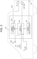
- Fig. 3 is a block configuration diagram of the display device, and elements corresponding to those illustrated in Fig. 1 are denoted by the same reference numerals.
- the ECU 100 includes an image processing unit 101, an object detection unit 102, and a display control unit 103.
- the image processing unit 101 performs signal processing on an imaging signal captured by the rear camera RC, and outputs an image signal.
- the object detection unit 102 outputs a detection signal to the display control unit 103 when an object is detected by the object sensor OS.
- the display control unit 103 displays the image signal from the image processing unit 101 on the monitor MO, and controls projection of the notification pattern CP by the left and right rear projectors LRP, RRP based on input driving information and the detection signal from the object sensor OS.
- Fig. 4 is a schematic configuration view of the left rear projector LRP as the first projection device.
- Two light source units 1, 2 and one projection lens 3 are incorporated in a casing 10.
- the projection lens 3 is formed of a plano-convex lens having a flat surface on a light incident side and a convex surface on a light emission side, and an optical axis Lx of the projection lens 3 faces substantially directly behind the automobile.
- the two light source units 1, 2 include two light sources 41, 42 mounted on one light source board 4 and two mask patterns 51, 52 formed on one non-transparent mask plate 5.
- the light source unit 1 includes the light source 41 and the mask pattern 51
- the light source unit 2 includes the light source 42 and the mask pattern 52.
- the light source units 1, 2 are arranged on the left and right sides in the vehicle width direction with respect to the optical axis Lx of the projection lens 3.
- the light source unit 1 on the left side in Fig. 4 is configured as a back light source unit that projects a back notification pattern BCP as a first notification pattern
- the light source unit 2 on the right side in Fig. 4 is configured as a rear turn light source unit that projects a rear turn notification pattern RTCP as a second notification pattern.
- the light source 41 of the back light source unit 1 includes a white LED that emits white light
- the light source 42 of the rear turn light source unit 2 includes an amber LED that emits amber light
- the pattern mask 51, 52 of each of the light source units 1, 2 is configured as three rectangular transparent windows arranged at predetermined intervals in the up-down direction in the non-transparent mask plate 5. The positions of the transparent windows 51, 52 in the up-down direction are shifted by a required dimension between the back light source unit 1 and the rear turn light source unit 2. For example, a milky white plate that diffuses and transmits light may be arranged in each of the transparent windows 51, 52.
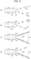
- Fig. 5(a) is a plan view of the notification pattern CP projected by the left rear projector LRP.
- a real image of the pattern mask 51 is projected as a white back notification pattern BCP in the form of a broken line on the road surface in rear of the automobile CAR.
- the back notification pattern BCP is projected so as to extend diagonally backward to the right from the rear portion of the automobile CAR.
- a real image of the pattern mask 52 is projected as an amber rear turn notification pattern RTCP in the form of a broken line on the road surface in rear of the automobile CAR.
- the rear turn notification pattern RTCP is projected so as to extend diagonally backward to the left from the rear portion of the automobile CAR.
- FIG. 5(b) is a plan view of the notification pattern projected by the right rear projector RRP, and the notification pattern is projected bilaterally symmetrically to the notification pattern projected by the left rear projector LRP. That is, when the white LED 41 of the back light source unit 1 emits light, the back notification pattern BCP extending diagonally backward to the left from the rear portion of the automobile CAR is projected. When the amber LED 42 of the rear turn light source unit 2 emits light, the rear turn notification pattern RTCP extending diagonally backward to the right from the rear portion of the automobile CAR is projected.
- the back notification pattern BCP and the rear turn notification pattern RTCP are projected by the left and right rear projectors LRP, RRP. At least part of these notification patterns BCP, RTCP is projected in the region Ac imaged by the rear camera RC as illustrated in Fig. 2 , and therefore, part of these notification patterns BCP, RTCP is displayed on the monitor MO and can be visually recognized by the driver.
- a backward movement signal is input to the ECU 100.
- the display control unit 103 controls the back light source units 1 of the left and right rear projectors LRP, RRP based on the backward movement signal, and projects the white back notification pattern BCP as the first notification pattern on the road surface in rear of the automobile.
- the display control unit 103 controls the left and right rear projectors LRP, RRP based on a steering signal, and projects the amber rear turn notification pattern on the rear road surface in the backward movement direction of the automobile.
- the inverted chevron-shaped rear turn notification pattern RTCP is projected so as to overlap with the back notification pattern BCP.
- the back notification patterns BCP of the left and right rear projectors LRP, RRP may be projected.
- the display control unit 103 controls the left and right rear projectors LRP, RRP based on the steering signal. For example, when the automobile CAR is moved backward while being steered leftward, as illustrated in Fig. 5(d) , the back notification patterns BCP are projected by the left and right rear projectors LRP, RRP, and the rear turn notification pattern RTCP is projected by the left rear projector LRP on the road surface diagonally on the rear left side of the automobile CAR so as to overlap with the back notification pattern BCP.
- the back notification patterns BCP are projected by the left and right rear projectors LRP, RRP, and the rear turn notification pattern RTCP is projected by the right rear projector RRP on the road surface diagonally on the rear right side of the automobile CAR.
- the rear turn notification pattern is projected with overlapping with the back notification pattern. Note that since the transparent windows of the pattern masks 51, 52 of the back light source unit 1 and the rear turn light source unit 2 are shifted in the up-down direction as described above, the back notification pattern BCP and the rear turn notification pattern RTCP are projected as the linear patterns alternately arranged in the extension direction.
- a third party on the rear side of the automobile CAR can recognize that the automobile CAR will move backward by visually recognizing the back notification pattern BCP.
- the third party can recognize that the automobile CAR will move to the right or the left. This allows the third party to take action to avoid danger.
- At least part of the projected back notification pattern BCP and at least part of the rear turn notification pattern RTCP are also projected on the imaging region Ac of the rear camera RC, and therefore, are captured by the rear camera RC.
- these notification patterns BCP, RTCP are displayed on the monitor MO.
- the driver can check the projected back notification pattern BCP and rear turn notification pattern RTCP when checking the region in rear of the automobile CAR by visually recognizing the monitor MO.
- both the third party and the driver visually recognize the back notification pattern BCP and the rear turn notification pattern RTCP, so that safety while the automobile CAR is traveling is ensured.
- the driver can confirm the third party by the monitor MO.
- the third party is outside the imaging region Ac, such as a case where a third party M1 is present on the outer right or left side of the imaging region Ac or a case where a third party M2 is in a crouching state
- these third parties M1, M2 are not imaged by the rear camera RC, and it is difficult to confirm the third parties M1, M2 on the monitor MO.
- the driver may erroneously recognize that there is no third party, which causes a problem in the safety while the automobile CAR is traveling.
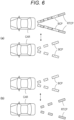
- the object detection unit 102 of the ECU 100 detects the third parties M1, M2 based on the detection signal from the object sensor OS. Then, the display control unit 103 controls the left and right rear projectors LRP, RRP based on the detection signal.
- the back notification pattern BCP is projected as usual (in a continuous lighting state), while the rear turn notification pattern RTCP is projected in a blinking state as illustrated in the upper view. That is, the notification patterns in the upper and lower views are alternately projected.
- the third party recognizes blinking of the rear turn notification pattern RTCP
- the driver of the automobile may not recognize the third party. This allows the third party to quickly take action to ensure one's safety.
- the driver can recognize that there is the third party not displayed on the monitor MO by checking blinking of the rear turn notification pattern RTCP on the monitor MO. As a result, the safety while the automobile is being traveled by the driver is ensured.
- the back notification pattern BCP and the rear turn notification pattern RTCP may be alternately projected in a blinking state as illustrated in the upper and lower views of Fig. 6(b) .
- the light emission amounts of the white LED and the amber LED as the light sources may be changed over time instead of blinking. In either case, as described above, both the third party and the driver can take action to ensure the safety while the automobile is traveling.
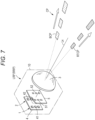
- Fig. 7 is a schematic configuration view of a left rear projector according to a modification of the first embodiment. Since a basic configuration of the first modification is the same as the basic configuration of the first embodiment, equivalent elements are denoted by the same reference numerals.
- a right rear projector is bilaterally symmetrical to the left rear projector.
- a plurality of white and amber LEDs corresponding to the number of transparent windows of the pattern mask 51, 52 are arranged as the light source 41, 42 in each of the back light source unit 1 and the rear turn light source unit 2, and light of each LED is emitted through the corresponding transparent window.
- the back notification pattern BCP and the rear turn notification pattern RTCP each having the linear pattern shape can be projected in series along the length direction, and can be projected so-called sequentially.
- Fig. 8 is a schematic perspective view of an automobile CAR equipped with a rear projector of a second embodiment. Elements equivalent to those in the first embodiment are denoted by the same reference numerals.
- no rear projectors are arranged in left and right rear combination lamps LRCL, RRCL of a vehicle body rear portion of an automobile, and one composite rear projector CRP is arranged between the left and right rear combination lamps LRCL, RRCL.
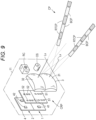
- the composite rear projector CRP is configured integrally with a rear camera RC and an object sensor OS, and is mounted on a vehicle body of the automobile CAR.
- Fig. 9 is a conceptual configuration view including the composite rear projector CRP, and the composite rear projector CRP, the rear camera RC, and the object sensor OS are installed in a casing 11.
- the composite rear projector CRP includes one projection lens 3 and two light source units 1, 2.
- the two light source units 1, 2 are arranged one above the other, and the lower light source unit 1 is configured as a back light source unit that projects a back notification pattern BCP.
- the upper light source unit 2 is configured as a rear turn light source unit that projects a rear turn notification pattern RTCP.
- the back light source unit 1 includes white LEDs 41 and pattern masks 51 as a first projection device, and the rear turn light source unit 2 includes amber LEDs 42 and pattern masks 52 as a second projection device.
- the projection lens 3 is a free curved surface lens configured such that two lens portions 31, 32 are arranged one above the other and integrally formed.
- the upper and lower lens portions 31, 32 are configured as independent projection lenses.
- the white LEDs 41 and the pattern masks 51 of the back light source unit 1 are arranged on the left and right sides with respect to an optical axis Lx of the lower lens portion 31, and from the pattern masks 51, a white back notification pattern BCP as a first notification pattern having an inverted chevron shape is projected by the lower lens portion 31.
- amber LEDs 42 and the pattern masks 52 of the rear turn light source unit 2 are arranged on the left and right sides with respect to the optical axis Lx of the upper lens portion 32, and from the pattern mask 52, an amber rear turn notification pattern RTCP as a second notification pattern having an inverted chevron shape is projected by the upper lens portion 32.
- the notification pattern projected by the composite rear projector CRP is basically the same as that in the first embodiment. That is, when the object sensor OS detects no object at the time of backward movement of the automobile CAR, as illustrated in Fig. 5(c) , the white LEDs 41 of the back light source unit 1 emit light to project the back notification pattern BCP, and the amber LEDs 42 of the rear turn light source unit 2 emit light to project the rear turn notification pattern RTCP. Alternatively, only the back notification pattern BCP may be projected. As illustrated in Fig. 5(d) , the amber LEDs 42 of the rear turn light source unit 2 selectively emit light according to the direction in which the automobile moves backward, so that the rear turn notification pattern RTCP is projected.
- either or both of the back notification pattern BCP and the rear turn notification pattern RTCP blink as in Figs. 6(a) and 6(b) .
- a third party can reliably recognize that the automobile will move backward.
- a driver can recognize the presence of the third party by visually recognizing these notification patterns BCP, RTCP on the monitor MO.
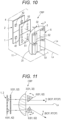
- Fig. 10 is a schematic configuration view of a rear projector of a third embodiment
- Fig. 11 is a schematic view of an optical path in a planar direction for describing the outline of the optical path.
- a basic configuration of the rear projector of the third embodiment is the same as the basic configuration of the second embodiment, and the rear projector of the third embodiment is configured as a composite rear projector CRP including a projection lens 3 including one free curved surface lens and two light source units 1, 2 for projecting a back notification pattern and a rear turn notification pattern.
- each of lower and upper lens portions 31, 32 of the projection lens 3 is configured such that the light incident side of each of the lens portions 31, 32 is a convex free curved surface and the light emission side of each of the lens portions 31, 32 is a flat surface. Pairs of movable prisms 6 arranged on the left and right sides with respect to an optical axis Lx are arranged on the light emission side of the lens portions 31, 32.
- the movable prisms 6 include lower movable prisms 61 arranged so as to face the lower lens portion 31 and lower movable prisms 62 arranged so as to face the upper lens portion 32.
- the movable prism 6 (61, 62) has a wedge-shaped planar shape, here, a triangular shape, and is turned horizontally in the left-right direction by an actuator (not illustrated) such as an electromagnetic actuator, so that an angle with respect to the light emission surface of each of the lens portions 31, 32, i.e., an angle with respect to the optical axis Lx, can be changed.
- the back notification pattern BCP is projected by the back light source unit 1, and the rear turn notification pattern RTCP is projected by the rear turn light source unit 2.
- the rear turn notification pattern RTCP is projected by the rear turn light source unit 2.
- light emitted from each of the light source units 1, 2 and focused by the projection lens 3 is refracted by each of the movable prisms 61, 62.
- the direction of emission of light from the projection lens 3 is changed by controlling the actuator in a display control unit 103 of an ECU 100 to adjust the angles of the movable prisms 61, 62.
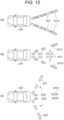
- two left and right back notification patterns BCP can be projected in a direction parallel to the front-rear direction of an automobile CAR as illustrated in Fig. 12(b) .
- the back notification patterns BCP can be projected in a state of being opened left and right with a great angle.
- the opening angle of the inverted chevron shape of the rear turn notification pattern RTCP can be changed.
- the projection angle of the back notification pattern BCP is continuously changed and the back notification pattern BCP is swivel-projected in such a manner that the angles of the lower movable prisms 61 are continuously changed over time with respect to the notification patterns BCP, RTCP in a steady state of Fig. 13(a) , for example, as in Fig. 13(b) .
- Fig. 13(c) by continuously changing the angles of the upper movable prisms 62 over time, the projection angle of the rear turn notification pattern RTCP is changed and the rear turn notification pattern RTCP is swivel-projected.
- the third party can reliably recognize that the automobile will move backward by swivel projection of the notification patterns BCP, RTCP.
- a driver can recognize the presence of the third party by visually recognizing the swivel-projection state of these notification patterns BCP, RTCP on the monitor MO.
- the notification pattern may blink.
- the notification pattern may be sequentially projected by providing a plurality of light sources as in the modification of the first embodiment.
- the present invention is not limited to these notification patterns.
- the projection direction of each notification pattern is not limited to the rear of the vehicle, and the present invention can also be applied to a case where a notification pattern is projected in a lateral direction which is likely to be a blind area of a vehicle.
- the projection form of each notification pattern, particularly the pattern shape and color of the notification pattern, and the projection form of the notification pattern when an object is detected are not limited to those in the embodiments.
Landscapes
- Engineering & Computer Science (AREA)
- Mechanical Engineering (AREA)
- Multimedia (AREA)
- General Engineering & Computer Science (AREA)
- Human Computer Interaction (AREA)
- Physics & Mathematics (AREA)
- General Physics & Mathematics (AREA)
- Lighting Device Outwards From Vehicle And Optical Signal (AREA)
- Arrangement Of Elements, Cooling, Sealing, Or The Like Of Lighting Devices (AREA)
Abstract
Description
- The present invention relates to a display device suitable for application to a vehicle, for example, an automobile, and more particularly to a vehicle display device, which includes a projection device that projects a notification pattern for notifying the behavior of a subject vehicle on a region including, e.g., a road surface in the vicinity of the subject vehicle.
- For the purpose of ensuring traffic safety, there has been proposed a display device for notifying a third party, such as a pedestrian or other vehicles, of the behavior of an automobile, for example, a traveling or stop state or a traveling direction.
Patent Literature 1 is a technique in which a display device including, e.g., a projector is mounted on an automobile and a notification pattern including a required design is projected on a road surface in front or rear of a subject vehicle by the projector. When a third party visually recognizes this notification pattern, the third party can recognize the behavior of the automobile and avoid contact with the automobile in advance. - For recent automobiles, as in
Patent Literature 2, there has also been proposed a technique in which an imager such as a camera that images a region which is a blind area of a driver is mounted and an image captured by the camera is displayed on a monitor. By visually checking the image on the monitor, the driver can recognize a third party present in the blind area, and can safely move the subject vehicle to suitable direction and position. -
- Patent Literature 1:
JP-A-2020-55519 - Patent Literature 2:
JP-A-2019-125920 - An imaging region of the camera and a region where a captured image is displayed on a monitor are limited, and in particular, regions diagonally on the rear left and right sides of an automobile have an unconfirmed region which is a blind area which cannot be checked on the monitor. In particular, it is difficult to check, on the monitor, a child, a person who has crouched, etc. In the technique of
Patent Literature 1, the third party can perceive danger of the third party oneself and take action to avoid the danger by visually recognizing the notification pattern, but on the other hand, a driver cannot recognize the presence of the third party and cannot perform driving to avoid the danger in some cases. - In addition, if the notification pattern is merely projected, the third party may not notice the notification pattern. In particular, it is difficult for a child who is difficult to be imaged by a camera or a person who has crouched to notice the notification pattern. On the other hand, even in a case where the third party visually recognizes the notification pattern, it may not be possible to accurately understand the behavior of the automobile intended by the notification pattern, and for example, it may be difficult for the third party to understand the degree of urgency of the danger to the third party oneself.
- An object of the present invention is to provide a display device that enables a third party to reliably recognize a projected notification pattern and enables safe traveling of a vehicle. Another object of the present invention is to provide a display device that enables an occupant of the vehicle to recognize the third party based on the notification pattern, thereby enabling further safe traveling of the vehicle.
- A vehicle display device according to the present invention includes a projection device that projects a notification pattern on a region in the vicinity of a vehicle, an imaging device that images the region in the vicinity of the vehicle, and an object detection device capable of detecting an object present in a region which cannot be imaged by the imaging device, and when the object detection device detects the object, the projection device projects the notification pattern in a form different from the notification pattern in a normal state. The imaging device is capable of imaging a region including at least a region on which the notification pattern is projected, and the captured image is displayed on a monitor visually checkable by an occupant of the vehicle.
- Preferably in the present invention, the notification pattern includes a first notification pattern and a second notification pattern that correspond to different movement modes of the vehicle, and at least one of a pattern shape or color is different between the first notification pattern and the second notification pattern. For example, at least one of the first notification pattern or the second notification pattern is projected in a blinking state when the object detection device detects the object. Alternatively, a projection position or a projection direction of at least one of the first notification pattern and the second notification pattern is changed when the object detection device detects the object.
- Preferably in the present invention, the projection device includes a first projection device that projects the first notification pattern and a second projection device that projects the second notification pattern. In this case, the first projection device and the second projection device are installed in a lamp housing of the vehicle. Alternatively, the first projection device and the second projection device are installed in one casing.
- According to the present invention, when the object present in the region which cannot be imaged by the imaging device is detected, the projection form of the notification pattern by the projection device is controlled, thereby enabling a third party who has visually recognized the notification pattern to recognize the behavior of the vehicle and further enabling a driver to recognize the presence of the third party based on the notification pattern. This enables safe traveling of the vehicle.
-
-
Fig. 1 is a schematic perspective view of an automobile equipped with a display device of a first embodiment; -
Fig. 2 is a view illustrating an imaging region of a rear camera and a detection region of an object sensor; -
Fig. 3 is a block configuration diagram of the display device of the first embodiment; -
Fig. 4 is a schematic configuration view of a left rear projector of the first embodiment; -
Fig. 5 is a conceptual view of a notification pattern by left and right rear projectors; -
Fig. 6 is a conceptual view of a projection form of the notification pattern at the time of object detection; -
Fig. 7 is a schematic configuration view of a left rear projector of a modification of the first embodiment; -
Fig. 8 is a schematic perspective view of an automobile equipped with a display device of a second embodiment; -
Fig. 9 is a schematic configuration view of a composite rear projector of the second embodiment; -
Fig. 10 is a schematic configuration view of a composite rear projector of a third embodiment; -
Fig. 11 is a schematic view of an optical path of the composite rear projector of the third embodiment; -
Fig. 12 is a conceptual view of a notification pattern by the composite rear projector of the third embodiment; and -
Fig. 13 is a conceptual view of the notification pattern by the composite rear projector of the third embodiment. - Next, embodiments of the present invention will be described with reference to the drawings.
Fig. 1 is a schematic perspective view of an automobile CAR equipped with a display device of a first embodiment of the present invention. A left rear combination lamp LRCL and a right rear combination lamp RRCL are each arranged on the left and right of a vehicle body rear portion of the automobile CAR. Although not illustrated, a tail lamp, a backup lamp, and a turn signal lamp are incorporated in a lamp housing of each of the left and right rear combination lamps LRCL, RRCL. - A left rear projector LRP is arranged inside the left rear combination lamp LRCL in a vehicle width direction, and a right rear projector RRP is arranged inside the right rear combination lamp RRCL in the vehicle width direction. The left and right rear projectors LRP, RRP are each configured as a first projection device and a second projection device that project a notification pattern CP (see
Fig. 4 ) having a required design on a road surface in rear of the automobile CAR. - A rear camera (back camera) RC as an imaging device is arranged in part of a trunk lid of the vehicle body rear portion of the automobile CAR, and as illustrated in
Fig. 2 , images a region in rear of the automobile CAR, particularly a region Ac including a road surface in rear of the automobile CAR. Since an existing camera using a semiconductor imaging element can be used as the rear camera RC, detailed description of the rear camera is omitted here. Further, the rear camera RC may be arranged at a position facing a rear window of the automobile CAR or a position in the vicinity of a license plate. - In addition, an object sensor OS that detects an object, particularly a human, present in the region in rear of the automobile is arranged in part of a rear bumper of the automobile CAR. The object sensor OS includes, for example, an infrared sensor. Detailed description of the infrared sensor will be omitted. As illustrated in
Fig. 2 , a rear region As targeted for detection by the object sensor OS is set particularly as a region wider in the left-right direction in rear of the automobile CAR, unlike the imaging region Ac of the rear camera RC. This region As includes a region which is a so-called blind area of the automobile CAR. - On the other hand, as illustrated in
Fig. 1 , a monitor MO is arranged at a position facing a driver's seat on a dashboard in a vehicle interior of the automobile CAR, and is configured such that a driver can visually recognize an image displayed on a display screen of the monitor MO. The monitor MO is connected to an electronic control unit (ECU) 100 together with the left and right rear projectors LRP, RRP, the rear camera RC, and the object sensor OS. The ECU 100 is capable of displaying an image captured by the rear camera RC on the display screen of the monitor MO and controlling the notification pattern CP projected by the left and right rear projectors LRP, RRP. In addition, theECU 100 is capable of controlling the projection form of the notification pattern CP when an object is detected by the object sensor OS. - Driving information indicating the driving state of the automobile CAR is input to the
ECU 100. Here, theECU 100 is connected to a shift lever SL and a steering wheel HA to be operated by the driver when the automobile moves backward, and backward movement information as the driving information is input from the shift lever SL and steering information is input from the steering wheel HA. Note that theECU 100 may be a vehicle ECU that controls the entirety of the automobile, a lamp ECU that controls a lamp of the automobile, or an ECU that independently controls other components. -
Fig. 3 is a block configuration diagram of the display device, and elements corresponding to those illustrated inFig. 1 are denoted by the same reference numerals. TheECU 100 includes animage processing unit 101, anobject detection unit 102, and adisplay control unit 103. Theimage processing unit 101 performs signal processing on an imaging signal captured by the rear camera RC, and outputs an image signal. Theobject detection unit 102 outputs a detection signal to thedisplay control unit 103 when an object is detected by the object sensor OS. Thedisplay control unit 103 displays the image signal from theimage processing unit 101 on the monitor MO, and controls projection of the notification pattern CP by the left and right rear projectors LRP, RRP based on input driving information and the detection signal from the object sensor OS. -
Fig. 4 is a schematic configuration view of the left rear projector LRP as the first projection device. Twolight source units projection lens 3 are incorporated in acasing 10. Theprojection lens 3 is formed of a plano-convex lens having a flat surface on a light incident side and a convex surface on a light emission side, and an optical axis Lx of theprojection lens 3 faces substantially directly behind the automobile. The twolight source units light sources light source board 4 and twomask patterns non-transparent mask plate 5. Thelight source unit 1 includes thelight source 41 and themask pattern 51, and thelight source unit 2 includes thelight source 42 and themask pattern 52. Theselight source units projection lens 3. Thelight source unit 1 on the left side inFig. 4 is configured as a back light source unit that projects a back notification pattern BCP as a first notification pattern, and thelight source unit 2 on the right side inFig. 4 is configured as a rear turn light source unit that projects a rear turn notification pattern RTCP as a second notification pattern. - The
light source 41 of the backlight source unit 1 includes a white LED that emits white light, and thelight source 42 of the rear turnlight source unit 2 includes an amber LED that emits amber light. Thepattern mask light source units non-transparent mask plate 5. The positions of thetransparent windows light source unit 1 and the rear turnlight source unit 2. For example, a milky white plate that diffuses and transmits light may be arranged in each of thetransparent windows -
Fig. 5(a) is a plan view of the notification pattern CP projected by the left rear projector LRP. When thewhite LED 41 of the backlight source unit 1 emits light, a real image of thepattern mask 51 is projected as a white back notification pattern BCP in the form of a broken line on the road surface in rear of the automobile CAR. The back notification pattern BCP is projected so as to extend diagonally backward to the right from the rear portion of the automobile CAR. When theamber LED 42 of the rear turnlight source unit 2 emits light, a real image of thepattern mask 52 is projected as an amber rear turn notification pattern RTCP in the form of a broken line on the road surface in rear of the automobile CAR. The rear turn notification pattern RTCP is projected so as to extend diagonally backward to the left from the rear portion of the automobile CAR. - Since the right rear projector RRP as the second projection device has a configuration bilaterally symmetrical to the left rear projector LRP, illustration of the right rear projector RRP is omitted.
Fig. 5(b) is a plan view of the notification pattern projected by the right rear projector RRP, and the notification pattern is projected bilaterally symmetrically to the notification pattern projected by the left rear projector LRP. That is, when thewhite LED 41 of the backlight source unit 1 emits light, the back notification pattern BCP extending diagonally backward to the left from the rear portion of the automobile CAR is projected. When theamber LED 42 of the rear turnlight source unit 2 emits light, the rear turn notification pattern RTCP extending diagonally backward to the right from the rear portion of the automobile CAR is projected. - Thus, when the left and right rear projectors LRP, RRP project the notification patterns at the same time, as illustrated in
Fig. 5(c) , one linear pattern extending such that the rear turn notification pattern RTCP from the left rear projector LRP and the back notification pattern BCP from the right rear projector RRP are alternately arranged diagonally backward to the right and one linear pattern extending such that the back notification pattern BCP from the left rear projector LRP and the rear turn notification pattern RTCP from the right rear projector RRP are alternately arranged diagonally backward to the left are projected in an inverted chevron shape. - As described above, the back notification pattern BCP and the rear turn notification pattern RTCP are projected by the left and right rear projectors LRP, RRP. At least part of these notification patterns BCP, RTCP is projected in the region Ac imaged by the rear camera RC as illustrated in
Fig. 2 , and therefore, part of these notification patterns BCP, RTCP is displayed on the monitor MO and can be visually recognized by the driver. - Operation of the display device having the above-described configuration will be described. When the driver operates the shift lever SL to move the automobile CAR backward, a backward movement signal is input to the
ECU 100. Thedisplay control unit 103 controls the backlight source units 1 of the left and right rear projectors LRP, RRP based on the backward movement signal, and projects the white back notification pattern BCP as the first notification pattern on the road surface in rear of the automobile. At this time, if the driver does not steer the steering wheel HA, thedisplay control unit 103 controls the left and right rear projectors LRP, RRP based on a steering signal, and projects the amber rear turn notification pattern on the rear road surface in the backward movement direction of the automobile. As a result, as illustrated inFig. 5(c) , the inverted chevron-shaped rear turn notification pattern RTCP is projected so as to overlap with the back notification pattern BCP. Alternatively, although not illustrated, only the back notification patterns BCP of the left and right rear projectors LRP, RRP may be projected. - When the driver operates the steering wheel HA to steer the automobile CAR to the rear left or right at the time of backward movement of the automobile CAR, the
display control unit 103 controls the left and right rear projectors LRP, RRP based on the steering signal. For example, when the automobile CAR is moved backward while being steered leftward, as illustrated inFig. 5(d) , the back notification patterns BCP are projected by the left and right rear projectors LRP, RRP, and the rear turn notification pattern RTCP is projected by the left rear projector LRP on the road surface diagonally on the rear left side of the automobile CAR so as to overlap with the back notification pattern BCP. - Although not illustrated, when the automobile CAR is moved backward while being steered rightward, the back notification patterns BCP are projected by the left and right rear projectors LRP, RRP, and the rear turn notification pattern RTCP is projected by the right rear projector RRP on the road surface diagonally on the rear right side of the automobile CAR. The rear turn notification pattern is projected with overlapping with the back notification pattern. Note that since the transparent windows of the pattern masks 51, 52 of the back
light source unit 1 and the rear turnlight source unit 2 are shifted in the up-down direction as described above, the back notification pattern BCP and the rear turn notification pattern RTCP are projected as the linear patterns alternately arranged in the extension direction. - When the back notification pattern BCP is projected in this manner, a third party on the rear side of the automobile CAR can recognize that the automobile CAR will move backward by visually recognizing the back notification pattern BCP. When the rear turn notification pattern RTCP is projected, the third party can recognize that the automobile CAR will move to the right or the left. This allows the third party to take action to avoid danger.
- On the other hand, at least part of the projected back notification pattern BCP and at least part of the rear turn notification pattern RTCP are also projected on the imaging region Ac of the rear camera RC, and therefore, are captured by the rear camera RC. Thus, these notification patterns BCP, RTCP are displayed on the monitor MO. The driver can check the projected back notification pattern BCP and rear turn notification pattern RTCP when checking the region in rear of the automobile CAR by visually recognizing the monitor MO. As described above, both the third party and the driver visually recognize the back notification pattern BCP and the rear turn notification pattern RTCP, so that safety while the automobile CAR is traveling is ensured.
- In a case where the third party is present in the imaging region Ac of the rear camera RC illustrated in
Fig. 2 , the driver can confirm the third party by the monitor MO. However, as illustrated inFig. 2 , in a case where the third party is outside the imaging region Ac, such as a case where a third party M1 is present on the outer right or left side of the imaging region Ac or a case where a third party M2 is in a crouching state, these third parties M1, M2 are not imaged by the rear camera RC, and it is difficult to confirm the third parties M1, M2 on the monitor MO. For this reason, the driver may erroneously recognize that there is no third party, which causes a problem in the safety while the automobile CAR is traveling. - In such a case, the
object detection unit 102 of theECU 100 detects the third parties M1, M2 based on the detection signal from the object sensor OS. Then, thedisplay control unit 103 controls the left and right rear projectors LRP, RRP based on the detection signal. For example, as illustrated in the lower view ofFig. 6(a) , the back notification pattern BCP is projected as usual (in a continuous lighting state), while the rear turn notification pattern RTCP is projected in a blinking state as illustrated in the upper view. That is, the notification patterns in the upper and lower views are alternately projected. Thus, when the third party recognizes blinking of the rear turn notification pattern RTCP, it can be assumed that the third party is not displayed on the monitor MO and the driver of the automobile may not recognize the third party. This allows the third party to quickly take action to ensure one's safety. On the other hand, the driver can recognize that there is the third party not displayed on the monitor MO by checking blinking of the rear turn notification pattern RTCP on the monitor MO. As a result, the safety while the automobile is being traveled by the driver is ensured. - Instead of blinking the rear turn notification pattern RTCP, the back notification pattern BCP and the rear turn notification pattern RTCP may be alternately projected in a blinking state as illustrated in the upper and lower views of
Fig. 6(b) . Further, although not illustrated, the light emission amounts of the white LED and the amber LED as the light sources may be changed over time instead of blinking. In either case, as described above, both the third party and the driver can take action to ensure the safety while the automobile is traveling. -
Fig. 7 is a schematic configuration view of a left rear projector according to a modification of the first embodiment. Since a basic configuration of the first modification is the same as the basic configuration of the first embodiment, equivalent elements are denoted by the same reference numerals. A right rear projector is bilaterally symmetrical to the left rear projector. In this modification, a plurality of white and amber LEDs corresponding to the number of transparent windows of thepattern mask light source light source unit 1 and the rear turnlight source unit 2, and light of each LED is emitted through the corresponding transparent window. Thus, by causing the plurality ofLEDs 41 or the plurality ofLEDs 42 to emit light in series, the back notification pattern BCP and the rear turn notification pattern RTCP each having the linear pattern shape can be projected in series along the length direction, and can be projected so-called sequentially. - Consequently, in the case of the forms of the first embodiment illustrated in
Figs. 6(a) and 6(b) , i.e., when the object sensor OS detects the third party, at least one of the back notification pattern BCP or the rear turn notification pattern RTCP is sequentially projected so that the third party can reliably recognize backward movement of the automobile and the backward movement direction of the automobile. In addition, the driver can reliably recognize the presence of the third party by visually recognizing such a sequentially-projected notification pattern on the monitor MO. -
Fig. 8 is a schematic perspective view of an automobile CAR equipped with a rear projector of a second embodiment. Elements equivalent to those in the first embodiment are denoted by the same reference numerals. In the second embodiment, no rear projectors are arranged in left and right rear combination lamps LRCL, RRCL of a vehicle body rear portion of an automobile, and one composite rear projector CRP is arranged between the left and right rear combination lamps LRCL, RRCL. The composite rear projector CRP is configured integrally with a rear camera RC and an object sensor OS, and is mounted on a vehicle body of the automobile CAR. -
Fig. 9 is a conceptual configuration view including the composite rear projector CRP, and the composite rear projector CRP, the rear camera RC, and the object sensor OS are installed in acasing 11. The composite rear projector CRP includes oneprojection lens 3 and twolight source units light source units light source unit 1 is configured as a back light source unit that projects a back notification pattern BCP. The upperlight source unit 2 is configured as a rear turn light source unit that projects a rear turn notification pattern RTCP. The backlight source unit 1 includeswhite LEDs 41 and pattern masks 51 as a first projection device, and the rear turnlight source unit 2 includesamber LEDs 42 and pattern masks 52 as a second projection device. - The
projection lens 3 is a free curved surface lens configured such that twolens portions lower lens portions white LEDs 41 and the pattern masks 51 of the backlight source unit 1 are arranged on the left and right sides with respect to an optical axis Lx of thelower lens portion 31, and from the pattern masks 51, a white back notification pattern BCP as a first notification pattern having an inverted chevron shape is projected by thelower lens portion 31. In addition, theamber LEDs 42 and the pattern masks 52 of the rear turnlight source unit 2 are arranged on the left and right sides with respect to the optical axis Lx of theupper lens portion 32, and from thepattern mask 52, an amber rear turn notification pattern RTCP as a second notification pattern having an inverted chevron shape is projected by theupper lens portion 32. - In the second embodiment, the notification pattern projected by the composite rear projector CRP is basically the same as that in the first embodiment. That is, when the object sensor OS detects no object at the time of backward movement of the automobile CAR, as illustrated in
Fig. 5(c) , thewhite LEDs 41 of the backlight source unit 1 emit light to project the back notification pattern BCP, and theamber LEDs 42 of the rear turnlight source unit 2 emit light to project the rear turn notification pattern RTCP. Alternatively, only the back notification pattern BCP may be projected. As illustrated inFig. 5(d) , theamber LEDs 42 of the rear turnlight source unit 2 selectively emit light according to the direction in which the automobile moves backward, so that the rear turn notification pattern RTCP is projected. - When the object sensor OS detects an object, either or both of the back notification pattern BCP and the rear turn notification pattern RTCP blink as in
Figs. 6(a) and 6(b) . Thus, as in the first embodiment, a third party can reliably recognize that the automobile will move backward. In addition, a driver can recognize the presence of the third party by visually recognizing these notification patterns BCP, RTCP on the monitor MO. -
Fig. 10 is a schematic configuration view of a rear projector of a third embodiment, andFig. 11 is a schematic view of an optical path in a planar direction for describing the outline of the optical path. A basic configuration of the rear projector of the third embodiment is the same as the basic configuration of the second embodiment, and the rear projector of the third embodiment is configured as a composite rear projector CRP including aprojection lens 3 including one free curved surface lens and twolight source units upper lens portions projection lens 3 is configured such that the light incident side of each of thelens portions lens portions movable prisms 6 arranged on the left and right sides with respect to an optical axis Lx are arranged on the light emission side of thelens portions - The
movable prisms 6 include lowermovable prisms 61 arranged so as to face thelower lens portion 31 and lowermovable prisms 62 arranged so as to face theupper lens portion 32. The movable prism 6 (61, 62) has a wedge-shaped planar shape, here, a triangular shape, and is turned horizontally in the left-right direction by an actuator (not illustrated) such as an electromagnetic actuator, so that an angle with respect to the light emission surface of each of thelens portions - In the third embodiment, as in the second embodiment, the back notification pattern BCP is projected by the back
light source unit 1, and the rear turn notification pattern RTCP is projected by the rear turnlight source unit 2. At this time, as illustrated inFig. 11 , light emitted from each of thelight source units projection lens 3 is refracted by each of themovable prisms projection lens 3 is changed by controlling the actuator in adisplay control unit 103 of anECU 100 to adjust the angles of themovable prisms movable prisms light source units projection lens 3 is deflected in the left-right direction, and the direction of projection of the notification patterns BCP, RTCP can be changed. - According to the third embodiment, by controlling the angles of the left and right lower
movable prisms 61 with respect to projection of the notification patterns BCP, RTCP in a steady state illustrated inFig. 12(a) , two left and right back notification patterns BCP can be projected in a direction parallel to the front-rear direction of an automobile CAR as illustrated inFig. 12(b) . Alternatively, as illustrated inFig. 12(c) , the back notification patterns BCP can be projected in a state of being opened left and right with a great angle. In addition, although not illustrated, by changing the angles of the left and right uppermovable prisms 62, the opening angle of the inverted chevron shape of the rear turn notification pattern RTCP can be changed. - On the other hand, when a third party is detected by an object sensor OS, the projection angle of the back notification pattern BCP is continuously changed and the back notification pattern BCP is swivel-projected in such a manner that the angles of the lower
movable prisms 61 are continuously changed over time with respect to the notification patterns BCP, RTCP in a steady state ofFig. 13(a) , for example, as inFig. 13(b) . Alternatively, as inFig. 13(c) , by continuously changing the angles of the uppermovable prisms 62 over time, the projection angle of the rear turn notification pattern RTCP is changed and the rear turn notification pattern RTCP is swivel-projected. The third party can reliably recognize that the automobile will move backward by swivel projection of the notification patterns BCP, RTCP. In addition, a driver can recognize the presence of the third party by visually recognizing the swivel-projection state of these notification patterns BCP, RTCP on the monitor MO. Also in the third embodiment, the notification pattern may blink. Alternatively, the notification pattern may be sequentially projected by providing a plurality of light sources as in the modification of the first embodiment. - In each of the above-described embodiments, the example where the first notification pattern and the second notification pattern are the back notification pattern and the rear turn notification pattern has been described, but the present invention is not limited to these notification patterns. In addition, the projection direction of each notification pattern is not limited to the rear of the vehicle, and the present invention can also be applied to a case where a notification pattern is projected in a lateral direction which is likely to be a blind area of a vehicle. In the present invention, the projection form of each notification pattern, particularly the pattern shape and color of the notification pattern, and the projection form of the notification pattern when an object is detected are not limited to those in the embodiments.
- The present international application claims priority based on
Japanese Patent Application No. 2021-126366 filed on August 2, 2021 Japanese Patent Application No. 2021-126366 - The above description of the specific embodiments of the present invention has been presented for the purpose of illustration. The embodiments are not intended to be exhaustive or to limit the invention as it is in the form described. It is obvious to those skilled in the art that many modifications and alterations are possible in light of the contents of the description above.
-
- 1
- Back Light Source Unit (First Projection Device)
- 2
- Rear Turn Light Source Unit (Second Projection Device)
- 3 (31, 32)
- Projection Lens
- 4 (41, 42)
- Light Source (LED)
- 5 (51, 52)
- Pattern Mask
- 6 (61, 62)
- Movable Prism
- 10, 11
- Casing
- 100
- ECU
- 101
- Information Processing Unit
- 102
- Obj ect Detection Unit (Obj ect Detection Device)
- 103
- Display Control Unit
- RP
- Rear Projector (Projection Device)
- CRP
- Composite Rear Projector (Projection Device)
- RC
- Rear Camera (Imaging Device)
- OS
- Object Sensor (Object Detection Device)
- BCP
- Back Notification Pattern (First Notification Pattern)
- RTCP
- Rear Turn Notification Pattern (Second Notification Pattern)
- MO
- Monitor
- As
- Obj ect Detection Region
- Ac
- Imaging Region
- M1, M2
- Third Party (Object)
Claims (10)
- A vehicle display device comprising:a projection device that projects a notification pattern on a region in vicinity of a vehicle;an imaging device that images the region in the vicinity of the vehicle; andan object detection device capable of detecting an object present in a region which cannot be imaged by the imaging device,wherein when the object detection device detects the object, the projection device projects the notification pattern in a form different from the notification pattern in a normal state.
- The vehicle display device according to claim 1, whereinthe imaging device is capable of imaging a region including at least a region on which the notification pattern is projected, anda captured image is displayed on a monitor visually checkable by an occupant of the vehicle.
- The vehicle display device according to claim 1 or 2, whereinthe notification pattern includes a first notification pattern and a second notification pattern that correspond to different movement modes of the vehicle, andat least one of a pattern shape or color is different between the first notification pattern and the second notification pattern.
- The vehicle display device according to claim 3, wherein at least one of the first notification pattern or the second notification pattern is projected in a blinking state when the object detection device detects the object.
- The vehicle display device according to claim 3, wherein a projection position or a projection direction of at least one of the first notification pattern and the second notification pattern is changed when the object detection device detects the object.
- The vehicle display device according to any one of claims 3 to 5, whereinthe projection device includes a first projection device that projects the first notification pattern, anda second projection device that projects the second notification pattern.
- The vehicle display device according to claim 6, wherein the first projection device and the second projection device are installed in a lamp housing of the vehicle.
- The vehicle display device according to claim 6, wherein the first projection device and the second projection device are installed in one casing.
- The vehicle display device according to any one of claims 6 to 8, whereinthe first projection device and the second projection device includea first light source unit and a second light source unit, anda projection lens that projects the first notification pattern and the second notification pattern by the light source units.
- The vehicle display device according to any one of claims 3 to 9, whereinthe first notification pattern is a back notification pattern projected when the vehicle moves backward, andthe second notification pattern is a turn notification pattern indicating a traveling direction of the vehicle.
Applications Claiming Priority (2)
| Application Number | Priority Date | Filing Date | Title |
|---|---|---|---|
| JP2021126366A JP2023021484A (en) | 2021-08-02 | 2021-08-02 | Display device of vehicle |
| PCT/JP2022/028467 WO2023013442A1 (en) | 2021-08-02 | 2022-07-22 | Display device for vehicle |
Publications (3)
| Publication Number | Publication Date |
|---|---|
| EP4383231A1 true EP4383231A1 (en) | 2024-06-12 |
| EP4383231A4 EP4383231A4 (en) | 2024-10-23 |
| EP4383231B1 EP4383231B1 (en) | 2025-09-24 |
Family
ID=85155610
Family Applications (1)
| Application Number | Title | Priority Date | Filing Date |
|---|---|---|---|
| EP22852866.7A Active EP4383231B1 (en) | 2021-08-02 | 2022-07-22 | Display device for vehicle |
Country Status (5)
| Country | Link |
|---|---|
| US (1) | US12466310B2 (en) |
| EP (1) | EP4383231B1 (en) |
| JP (1) | JP2023021484A (en) |
| CN (1) | CN117480542A (en) |
| WO (1) | WO2023013442A1 (en) |
Families Citing this family (2)
| Publication number | Priority date | Publication date | Assignee | Title |
|---|---|---|---|---|
| JP2025008319A (en) * | 2023-07-05 | 2025-01-20 | 株式会社小糸製作所 | Projection equipment |
| US20250354670A1 (en) * | 2024-05-17 | 2025-11-20 | Toyota Motor North America, Inc. | Methods, systems, and devices for a selectable multicolor vehicle light |
Family Cites Families (19)
| Publication number | Priority date | Publication date | Assignee | Title |
|---|---|---|---|---|
| JP4367232B2 (en) * | 2004-05-20 | 2009-11-18 | トヨタ自動車株式会社 | Vehicle lighting device |
| JP4720650B2 (en) * | 2006-06-30 | 2011-07-13 | アイシン・エィ・ダブリュ株式会社 | Road surface projection apparatus and road surface projection method |
| JP2008009941A (en) * | 2006-06-30 | 2008-01-17 | Aisin Seiki Co Ltd | Vehicle notification device and vehicle notification method |
| JPWO2011013813A1 (en) * | 2009-07-30 | 2013-01-10 | クラリオン株式会社 | In-vehicle device and image processing program |
| KR101295833B1 (en) * | 2011-07-08 | 2013-08-12 | 에스엘 주식회사 | Automotive turn signal lamp and cotrolling method for the same |
| DE112014006874B4 (en) * | 2014-08-19 | 2025-11-06 | Mitsubishi Electric Corporation | Street surface lighting system |
| WO2016114048A1 (en) * | 2015-01-13 | 2016-07-21 | 日立マクセル株式会社 | Image projection device |
| JP6548593B2 (en) * | 2016-02-27 | 2019-07-24 | アルパイン株式会社 | Parking assistance apparatus and parking assistance method |
| JP6447545B2 (en) | 2016-03-11 | 2019-01-09 | トヨタ自動車株式会社 | Vehicle lighting device |
| WO2017164328A1 (en) * | 2016-03-24 | 2017-09-28 | 株式会社小糸製作所 | Vehicle lamp, vehicle lamp control system, and vehicle provided with vehicle lamp and vehicle lamp control system |
| CN111065547B (en) * | 2017-09-15 | 2022-12-06 | 三菱电机株式会社 | Irradiation apparatus and irradiation method |
| DE102017222816A1 (en) | 2017-12-14 | 2019-06-19 | Bayerische Motoren Werke Aktiengesellschaft | Marking a ground area representing a detection area of a vehicle-side environment sensor system |
| JP7160301B2 (en) | 2018-01-17 | 2022-10-25 | 株式会社ジャパンディスプレイ | MONITOR DISPLAY SYSTEM AND ITS DISPLAY METHOD |
| EP3835128A4 (en) | 2018-08-06 | 2021-09-08 | Koito Manufacturing Co., Ltd. | VEHICLE DISPLAY SYSTEM AND VEHICLE |
| JP7309724B2 (en) | 2018-08-15 | 2023-07-18 | 株式会社小糸製作所 | Vehicle display system and vehicle |
| CN112770939A (en) | 2018-09-25 | 2021-05-07 | 株式会社小糸制作所 | Lamp system and vehicle lamp |
| JP7856384B2 (en) | 2018-09-28 | 2026-05-11 | 株式会社小糸製作所 | Vehicle departure notification display device |
| JP7508455B2 (en) * | 2019-07-05 | 2024-07-01 | 株式会社小糸製作所 | Vehicle lighting fixtures |
| JP7381361B2 (en) | 2020-02-14 | 2023-11-15 | キヤノンメディカルシステムズ株式会社 | X-ray CT device |
-
2021
- 2021-08-02 JP JP2021126366A patent/JP2023021484A/en active Pending
-
2022
- 2022-07-22 WO PCT/JP2022/028467 patent/WO2023013442A1/en not_active Ceased
- 2022-07-22 EP EP22852866.7A patent/EP4383231B1/en active Active
- 2022-07-22 CN CN202280042323.XA patent/CN117480542A/en active Pending
- 2022-07-22 US US18/575,599 patent/US12466310B2/en active Active
Also Published As
| Publication number | Publication date |
|---|---|
| US20240308422A1 (en) | 2024-09-19 |
| US12466310B2 (en) | 2025-11-11 |
| EP4383231A4 (en) | 2024-10-23 |
| EP4383231B1 (en) | 2025-09-24 |
| CN117480542A (en) | 2024-01-30 |
| JP2023021484A (en) | 2023-02-14 |
| WO2023013442A1 (en) | 2023-02-09 |
Similar Documents
| Publication | Publication Date | Title |
|---|---|---|
| US10384596B2 (en) | System for detecting surrounding conditions of moving body | |
| KR101760995B1 (en) | Driving support apparatus for vehicle | |
| US10126640B2 (en) | Headlight control apparatus for performing control of a headlight device | |
| CN105163972B (en) | Information display system and information display device | |
| US9493072B2 (en) | Safety confirmation support system for vehicle driver and method for supporting safety confirmation of vehicle driver | |
| US12466310B2 (en) | Display device for vehicle | |
| CN110834583B (en) | Display system for vehicle and vehicle | |
| CN109789782B (en) | Projection type display device, projection display method, and storage medium | |
| CN107107761A (en) | Projection display device and driving assistance method | |
| CN113448096B (en) | Display device for vehicle | |
| CN109311419B (en) | Method for controlling the automatic display of a pictogram representing the imminent opening of a door | |
| JP6338626B2 (en) | Vehicle display device | |
| CN109789783B (en) | Projection display device, display control method, and computer-readable storage medium | |
| US10442339B2 (en) | Vehicle light emitting device | |
| CN106662799A (en) | Motor vehicle with lighting device for projecting images | |
| JP2009292223A (en) | Warning display device for vehicle | |
| CN112770936A (en) | Lamp system | |
| JP2002274258A (en) | Automotive night vision system | |
| JP4566121B2 (en) | Vehicle lighting device | |
| JP7433188B2 (en) | Imaging devices, mobile displays, and driver monitoring systems | |
| EP4375157A1 (en) | Control device for vehicle | |
| JP5447267B2 (en) | Vehicle display device | |
| CN113632154A (en) | Vehicles and signs for vehicles | |
| CN119585151A (en) | Road surface drawing device for vehicle and road surface drawing method for vehicle | |
| WO2022220039A1 (en) | Occupant monitoring system |
Legal Events
| Date | Code | Title | Description |
|---|---|---|---|
| STAA | Information on the status of an ep patent application or granted ep patent |
Free format text: STATUS: THE INTERNATIONAL PUBLICATION HAS BEEN MADE |
|
| PUAI | Public reference made under article 153(3) epc to a published international application that has entered the european phase |
Free format text: ORIGINAL CODE: 0009012 |
|
| STAA | Information on the status of an ep patent application or granted ep patent |
Free format text: STATUS: REQUEST FOR EXAMINATION WAS MADE |
|
| 17P | Request for examination filed |
Effective date: 20231227 |
|
| AK | Designated contracting states |
Kind code of ref document: A1 Designated state(s): AL AT BE BG CH CY CZ DE DK EE ES FI FR GB GR HR HU IE IS IT LI LT LU LV MC MK MT NL NO PL PT RO RS SE SI SK SM TR |
|
| REG | Reference to a national code |
Ref country code: DE Ref legal event code: R079 Free format text: PREVIOUS MAIN CLASS: G08G0001160000 Ipc: B60Q0001000000 Ref document number: 602022022082 Country of ref document: DE |
|
| A4 | Supplementary search report drawn up and despatched |
Effective date: 20240925 |
|
| RIC1 | Information provided on ipc code assigned before grant |
Ipc: B60Q 1/50 20060101ALI20240919BHEP Ipc: F21V 5/00 20180101ALI20240919BHEP Ipc: F21V 23/00 20150101ALI20240919BHEP Ipc: B60Q 1/26 20060101ALI20240919BHEP Ipc: B60Q 1/00 20060101AFI20240919BHEP |
|
| DAV | Request for validation of the european patent (deleted) | ||
| DAX | Request for extension of the european patent (deleted) | ||
| REG | Reference to a national code |
Ref country code: DE Ref legal event code: R079 Free format text: PREVIOUS MAIN CLASS: B60Q0001000000 Ipc: B60Q0001220000 Ref document number: 602022022082 Country of ref document: DE |
|
| RIC1 | Information provided on ipc code assigned before grant |
Ipc: B60Q 1/52 20060101ALI20250122BHEP Ipc: G08G 1/16 20060101ALI20250122BHEP Ipc: B60Q 9/00 20060101ALI20250122BHEP Ipc: B60Q 1/50 20060101ALI20250122BHEP Ipc: B60Q 1/34 20060101ALI20250122BHEP Ipc: B60Q 1/22 20060101AFI20250122BHEP |
|
| GRAP | Despatch of communication of intention to grant a patent |
Free format text: ORIGINAL CODE: EPIDOSNIGR1 |
|
| STAA | Information on the status of an ep patent application or granted ep patent |
Free format text: STATUS: GRANT OF PATENT IS INTENDED |
|
| GRAJ | Information related to disapproval of communication of intention to grant by the applicant or resumption of examination proceedings by the epo deleted |
Free format text: ORIGINAL CODE: EPIDOSDIGR1 |
|
| STAA | Information on the status of an ep patent application or granted ep patent |
Free format text: STATUS: REQUEST FOR EXAMINATION WAS MADE |
|
| INTG | Intention to grant announced |
Effective date: 20250303 |
|
| INTC | Intention to grant announced (deleted) | ||
| GRAP | Despatch of communication of intention to grant a patent |
Free format text: ORIGINAL CODE: EPIDOSNIGR1 |
|
| STAA | Information on the status of an ep patent application or granted ep patent |
Free format text: STATUS: GRANT OF PATENT IS INTENDED |
|
| INTG | Intention to grant announced |
Effective date: 20250502 |
|
| P01 | Opt-out of the competence of the unified patent court (upc) registered |
Free format text: CASE NUMBER: APP_29003/2025 Effective date: 20250618 |
|
| GRAS | Grant fee paid |
Free format text: ORIGINAL CODE: EPIDOSNIGR3 |
|
| GRAA | (expected) grant |
Free format text: ORIGINAL CODE: 0009210 |
|
| STAA | Information on the status of an ep patent application or granted ep patent |
Free format text: STATUS: THE PATENT HAS BEEN GRANTED |
|
| AK | Designated contracting states |
Kind code of ref document: B1 Designated state(s): AL AT BE BG CH CY CZ DE DK EE ES FI FR GB GR HR HU IE IS IT LI LT LU LV MC MK MT NL NO PL PT RO RS SE SI SK SM TR |
|
| REG | Reference to a national code |
Ref country code: GB Ref legal event code: FG4D |
|
| REG | Reference to a national code |
Ref country code: CH Ref legal event code: EP |
|
| REG | Reference to a national code |
Ref country code: DE Ref legal event code: R096 Ref document number: 602022022082 Country of ref document: DE |
|
| REG | Reference to a national code |
Ref country code: IE Ref legal event code: FG4D |
|
| PG25 | Lapsed in a contracting state [announced via postgrant information from national office to epo] |
Ref country code: NO Free format text: LAPSE BECAUSE OF FAILURE TO SUBMIT A TRANSLATION OF THE DESCRIPTION OR TO PAY THE FEE WITHIN THE PRESCRIBED TIME-LIMIT Effective date: 20251224 |
|
| REG | Reference to a national code |
Ref country code: LT Ref legal event code: MG9D |
|
| PG25 | Lapsed in a contracting state [announced via postgrant information from national office to epo] |
Ref country code: FI Free format text: LAPSE BECAUSE OF FAILURE TO SUBMIT A TRANSLATION OF THE DESCRIPTION OR TO PAY THE FEE WITHIN THE PRESCRIBED TIME-LIMIT Effective date: 20250924 |
|
| PG25 | Lapsed in a contracting state [announced via postgrant information from national office to epo] |
Ref country code: HR Free format text: LAPSE BECAUSE OF FAILURE TO SUBMIT A TRANSLATION OF THE DESCRIPTION OR TO PAY THE FEE WITHIN THE PRESCRIBED TIME-LIMIT Effective date: 20250924 |
|
| PG25 | Lapsed in a contracting state [announced via postgrant information from national office to epo] |
Ref country code: GR Free format text: LAPSE BECAUSE OF FAILURE TO SUBMIT A TRANSLATION OF THE DESCRIPTION OR TO PAY THE FEE WITHIN THE PRESCRIBED TIME-LIMIT Effective date: 20251225 |
|
| PG25 | Lapsed in a contracting state [announced via postgrant information from national office to epo] |
Ref country code: SE Free format text: LAPSE BECAUSE OF FAILURE TO SUBMIT A TRANSLATION OF THE DESCRIPTION OR TO PAY THE FEE WITHIN THE PRESCRIBED TIME-LIMIT Effective date: 20250924 |
|
| PG25 | Lapsed in a contracting state [announced via postgrant information from national office to epo] |
Ref country code: LV Free format text: LAPSE BECAUSE OF FAILURE TO SUBMIT A TRANSLATION OF THE DESCRIPTION OR TO PAY THE FEE WITHIN THE PRESCRIBED TIME-LIMIT Effective date: 20250924 |
|
| PG25 | Lapsed in a contracting state [announced via postgrant information from national office to epo] |
Ref country code: BG Free format text: LAPSE BECAUSE OF FAILURE TO SUBMIT A TRANSLATION OF THE DESCRIPTION OR TO PAY THE FEE WITHIN THE PRESCRIBED TIME-LIMIT Effective date: 20250924 |
|
| PG25 | Lapsed in a contracting state [announced via postgrant information from national office to epo] |
Ref country code: RS Free format text: LAPSE BECAUSE OF FAILURE TO SUBMIT A TRANSLATION OF THE DESCRIPTION OR TO PAY THE FEE WITHIN THE PRESCRIBED TIME-LIMIT Effective date: 20251224 |
|
| REG | Reference to a national code |
Ref country code: NL Ref legal event code: MP Effective date: 20250924 |
|
| PG25 | Lapsed in a contracting state [announced via postgrant information from national office to epo] |
Ref country code: NL Free format text: LAPSE BECAUSE OF FAILURE TO SUBMIT A TRANSLATION OF THE DESCRIPTION OR TO PAY THE FEE WITHIN THE PRESCRIBED TIME-LIMIT Effective date: 20250924 |
|
| REG | Reference to a national code |
Ref country code: AT Ref legal event code: MK05 Ref document number: 1840146 Country of ref document: AT Kind code of ref document: T Effective date: 20250924 |
|
| PG25 | Lapsed in a contracting state [announced via postgrant information from national office to epo] |
Ref country code: SM Free format text: LAPSE BECAUSE OF FAILURE TO SUBMIT A TRANSLATION OF THE DESCRIPTION OR TO PAY THE FEE WITHIN THE PRESCRIBED TIME-LIMIT Effective date: 20250924 |
|
| PG25 | Lapsed in a contracting state [announced via postgrant information from national office to epo] |
Ref country code: ES Free format text: LAPSE BECAUSE OF FAILURE TO SUBMIT A TRANSLATION OF THE DESCRIPTION OR TO PAY THE FEE WITHIN THE PRESCRIBED TIME-LIMIT Effective date: 20250924 |
|
| PG25 | Lapsed in a contracting state [announced via postgrant information from national office to epo] |
Ref country code: AT Free format text: LAPSE BECAUSE OF FAILURE TO SUBMIT A TRANSLATION OF THE DESCRIPTION OR TO PAY THE FEE WITHIN THE PRESCRIBED TIME-LIMIT Effective date: 20250924 |
|
| PG25 | Lapsed in a contracting state [announced via postgrant information from national office to epo] |
Ref country code: IT Free format text: LAPSE BECAUSE OF FAILURE TO SUBMIT A TRANSLATION OF THE DESCRIPTION OR TO PAY THE FEE WITHIN THE PRESCRIBED TIME-LIMIT Effective date: 20250924 |
|
| PG25 | Lapsed in a contracting state [announced via postgrant information from national office to epo] |
Ref country code: IS Free format text: LAPSE BECAUSE OF FAILURE TO SUBMIT A TRANSLATION OF THE DESCRIPTION OR TO PAY THE FEE WITHIN THE PRESCRIBED TIME-LIMIT Effective date: 20260124 |
|
| PG25 | Lapsed in a contracting state [announced via postgrant information from national office to epo] |
Ref country code: PT Free format text: LAPSE BECAUSE OF FAILURE TO SUBMIT A TRANSLATION OF THE DESCRIPTION OR TO PAY THE FEE WITHIN THE PRESCRIBED TIME-LIMIT Effective date: 20260126 Ref country code: CZ Free format text: LAPSE BECAUSE OF FAILURE TO SUBMIT A TRANSLATION OF THE DESCRIPTION OR TO PAY THE FEE WITHIN THE PRESCRIBED TIME-LIMIT Effective date: 20250924 |
|
| PG25 | Lapsed in a contracting state [announced via postgrant information from national office to epo] |
Ref country code: PL Free format text: LAPSE BECAUSE OF FAILURE TO SUBMIT A TRANSLATION OF THE DESCRIPTION OR TO PAY THE FEE WITHIN THE PRESCRIBED TIME-LIMIT Effective date: 20250924 |
|
| PG25 | Lapsed in a contracting state [announced via postgrant information from national office to epo] |
Ref country code: EE Free format text: LAPSE BECAUSE OF FAILURE TO SUBMIT A TRANSLATION OF THE DESCRIPTION OR TO PAY THE FEE WITHIN THE PRESCRIBED TIME-LIMIT Effective date: 20250924 Ref country code: SK Free format text: LAPSE BECAUSE OF FAILURE TO SUBMIT A TRANSLATION OF THE DESCRIPTION OR TO PAY THE FEE WITHIN THE PRESCRIBED TIME-LIMIT Effective date: 20250924 |