EP4383040A1 - Vehicular pedal - Google Patents
Vehicular pedal Download PDFInfo
- Publication number
- EP4383040A1 EP4383040A1 EP22880990.1A EP22880990A EP4383040A1 EP 4383040 A1 EP4383040 A1 EP 4383040A1 EP 22880990 A EP22880990 A EP 22880990A EP 4383040 A1 EP4383040 A1 EP 4383040A1
- Authority
- EP
- European Patent Office
- Prior art keywords
- hollow arm
- pedal
- wall
- seat
- components
- Prior art date
- Legal status (The legal status is an assumption and is not a legal conclusion. Google has not performed a legal analysis and makes no representation as to the accuracy of the status listed.)
- Pending
Links
Images


Classifications
-
- G—PHYSICS
- G05—CONTROLLING; REGULATING
- G05G—CONTROL DEVICES OR SYSTEMS INSOFAR AS CHARACTERISED BY MECHANICAL FEATURES ONLY
- G05G1/00—Controlling members, e.g. knobs or handles; Assemblies or arrangements thereof; Indicating position of controlling members
- G05G1/30—Controlling members actuated by foot
- G05G1/50—Manufacturing of pedals; Pedals characterised by the material used
- G05G1/506—Controlling members for foot-actuation
-
- G—PHYSICS
- G05—CONTROLLING; REGULATING
- G05G—CONTROL DEVICES OR SYSTEMS INSOFAR AS CHARACTERISED BY MECHANICAL FEATURES ONLY
- G05G1/00—Controlling members, e.g. knobs or handles; Assemblies or arrangements thereof; Indicating position of controlling members
- G05G1/30—Controlling members actuated by foot
- G05G1/44—Controlling members actuated by foot pivoting
Definitions
- the present disclosure relates to a vehicle pedal.
- Vehicle pedals include a brake pedal, a clutch pedal, and an accelerator pedal.
- a vehicle pedal disclosed in Patent Literature 1 includes a hollow arm and a pedal seat.
- the hollow arm is formed by two components with a specified length and pivotally supported by the vehicle body. Specifically, each flat component includes a recess extending in the longitudinal direction of the component.
- the hollow arm is formed by joining the two components with each other with the recesses of the two components being opposed to each other.
- the hollow arm includes an opening at a first end in the longitudinal direction.
- the hollow arm includes a wall that forms the opening at the first end.
- the pedal seat is arranged at the first end of the hollow arm and welded to the wall.
- Patent Literature 1 Japanese Laid-Open Patent Publication No. 2015-102892
- the wall of the hollow arm includes straight portions corresponding to the bottoms of the recesses and corner portions corresponding to the corners of the bottoms of the recesses. Welding the pedal seat to the corner portions of the wall is challenging because of space constraints during welding operations. Thus, the pedal seat is welded to the straight portions of the wall.
- the pedal force of the user applied to the pedal seat results in the following. Specifically, the load based on the pedal force acts on the pedal seat to twist the pedal seat relative to the hollow arm. As a result of the load applied to the pedal seat, the corner portions, which are not welded to the pedal seat, may be distorted and widened.
- a vehicle pedal is provided.
- the vehicle panel includes a hollow arm including two components with a specified length and a pedal seat.
- the components each include a recess extending in a longitudinal direction of the corresponding component.
- the two components are joined with each other with the recesses being opposed to each other.
- the hollow arm includes a wall that forms an opening at a first end of the hollow arm in a longitudinal direction.
- the pedal seat is arranged at the first end and welded to the wall.
- the wall includes a straight portion and a corner portion. The straight portion is welded to the pedal seat.
- the corner portion includes a reinforced portion configured to restrict distortion of the corner portion when a pedal force from a user is applied to the pedal seat.
- a vehicle pedal according to one embodiment will now be described with reference to Figs. 1 to 7 .
- the vehicle pedal includes a hollow arm 11 and a pedal seat 12.
- the hollow arm 11 is formed to have a specified length.
- a hole 13 is formed in the upper end of the hollow arm 11.
- the upper end of the hollow arm 11 may be referred to as a second end.
- a support shaft 14 is inserted through the hole 13.
- the support shaft 14 is fixed to the body of the vehicle.
- the hollow arm 11 is pivotally supported by the support shaft 14.
- the pedal seat 12 is arranged at the lower end of the hollow arm 11, in other words, an end opposite to the upper end at which the hole 13 is formed.
- the pedal seat 12 is welded to the lower end.
- the lower end of the hollow arm 11 may be referred to as a first end.
- a pedal force, generated when the user depresses the vehicle pedal, is applied to the pedal seat 12.
- the vehicle pedal is pivoted about a central axis L1 of the hole 13 and the support shaft 14.
- Fig. 2 shows the hollow arm 11 in Fig. 1 taken along line II-II.
- the hollow arm 11 is formed by two components, specifically, a first component 11a and a second component 11b.
- the first and second components 11a and 11b are formed by bending elongated plates with a specified length.
- the first and second components 11a and 11b respectively include a first recess 15 and a second recess 16 that extend in the longitudinal direction of the first and second components 11a and 11b (direction intersecting the page of Fig. 2 ).
- the hollow arm 11 is formed by joining the first and second components 11a and 11b with each other with the first and second recesses 15 and 16 of the first and second components 11a and 11b being opposed to each other.
- the hollow arm 11 includes an opening 17 at the lower end.
- the hollow arm 11 includes a wall 18 that forms the opening 17 at the lower end.
- the wall 18 is an end region of a predetermined area of the hollow arm 11 in the longitudinal direction.
- the wall 18 may be referred to as an opening forming portion.
- an open portion 18a is formed so that the inside of the hollow arm 11 is open downward.
- the wall 18 includes a first straight portion 19, a second straight portion 20, a first corner portion 21, and a second corner portion 22.
- the first and second straight portions 19 and 20 are arranged, respectively, at the bottoms of the first and second recesses 15 and 16 of the first and second components 11a and 11b.
- the first and second straight portions 19 and 20 are located at the opposite sides of the hollow arm 11.
- the first and second straight portions 19 and 20 extend linearly when the wall 18 is viewed from the direction facing the opening 17.
- the first and second straight portions 19 and 20 are opposed and substantially parallel to each other.
- the first and second straight portions 19 and 20 may be referred to as first and second flat portions.
- the first and second corner portions 21 and 22 are arranged, respectively, at the corners of the bottoms of the first and second recesses 15 and 16, and connected, respectively, to the first and second straight portions 19 and 20.
- the pedal seat 12 shown in Fig. 4 is welded to the first and second straight portions 19 and 20 of the wall 18. However, the pedal seat 12 is not welded to the first and second corner portions 21 and 22 of the wall 18. This is because it is difficult to secure space required for operations when the pedal seat 12 is welded to the first and second corner portions 21 and 22.
- a first bead 23 and a second bead 24 are arranged, respectively, on the wall 18 to extend across the ridges (vertices) of the first and second corner portions 21 and 22.
- the first and second beads 23 and 24 are shaped to bulge toward the center of the opening 17 and located near the edges of the wall 18 (end surfaces forming opening 17).
- the first and second beads 23 and 24 are recessed when viewed from the outside of the hollow arm 11.
- the first and second beads 23 and 24 are raised when viewed from the inside of the hollow arm 11.
- the first and second beads 23 and 24 serve as reinforced portions that restrict distortion of the first and second corner portions 21 and 22 when a pedal force from the user is applied to the pedal seat 12.
- Figs. 6 and 7 show the vehicle pedal in Fig. 1 viewed from the front and the side, respectively.
- the lower end of the hollow arm 11 at which the pedal seat 12 is arranged is offset from the upper end, where the hole 13 is formed, in a direction in which the central axis L1 of the hole 13 extends (rightward in Fig. 6 ).
- This is because of limitations on the location where the vehicle pedal is attached to the vehicle body and the location of the vehicle seat on which the user is seated.
- the offset design allows the user to appropriately operate the vehicle pedal under such limitations.
- the lower end of the hollow arm 11 is curved so that a central axis L2 of the opening 17 ( Fig. 6 ) is inclined toward the central axis L1 of the hole 13 ( Fig. 6 ).
- the lower end of the hollow arm 11 is curved so that the opening 17 is oriented toward a side at which the upper end of the hollow arm 11 is located in relation to the lower end.
- the vehicle pedal according to the present embodiment has the advantages described below.
- the first and second beads 23 and 24 may be shaped to bulge in a direction extending away from the center of the opening 17.
- the first and second beads 23 and 24 do not need to be located near the edges of the wall 18.
- the lower end of the hollow arm 11 at which the pedal seat 12 is arranged does not need to be offset from the upper end, where the hole 13 is formed, in the direction in which the central axis L1 of the hole 13 extends.
Landscapes
- Engineering & Computer Science (AREA)
- Physics & Mathematics (AREA)
- General Physics & Mathematics (AREA)
- Automation & Control Theory (AREA)
- Manufacturing & Machinery (AREA)
- Mechanical Control Devices (AREA)
Abstract
Description
- The present disclosure relates to a vehicle pedal.
- Vehicle pedals include a brake pedal, a clutch pedal, and an accelerator pedal. A vehicle pedal disclosed in Patent Literature 1 includes a hollow arm and a pedal seat. The hollow arm is formed by two components with a specified length and pivotally supported by the vehicle body. Specifically, each flat component includes a recess extending in the longitudinal direction of the component. The hollow arm is formed by joining the two components with each other with the recesses of the two components being opposed to each other. The hollow arm includes an opening at a first end in the longitudinal direction. The hollow arm includes a wall that forms the opening at the first end. The pedal seat is arranged at the first end of the hollow arm and welded to the wall.
- Patent Literature 1:
Japanese Laid-Open Patent Publication No. 2015-102892 - The wall of the hollow arm includes straight portions corresponding to the bottoms of the recesses and corner portions corresponding to the corners of the bottoms of the recesses. Welding the pedal seat to the corner portions of the wall is challenging because of space constraints during welding operations. Thus, the pedal seat is welded to the straight portions of the wall.
- However, when a user depresses the vehicle pedal, the pedal force of the user applied to the pedal seat results in the following. Specifically, the load based on the pedal force acts on the pedal seat to twist the pedal seat relative to the hollow arm. As a result of the load applied to the pedal seat, the corner portions, which are not welded to the pedal seat, may be distorted and widened.
- According to one aspect of the present disclosure, a vehicle pedal is provided. The vehicle panel includes a hollow arm including two components with a specified length and a pedal seat. The components each include a recess extending in a longitudinal direction of the corresponding component. The two components are joined with each other with the recesses being opposed to each other. The hollow arm includes a wall that forms an opening at a first end of the hollow arm in a longitudinal direction. The pedal seat is arranged at the first end and welded to the wall. The wall includes a straight portion and a corner portion. The straight portion is welded to the pedal seat. The corner portion includes a reinforced portion configured to restrict distortion of the corner portion when a pedal force from a user is applied to the pedal seat.
-
-
Fig. 1 is a perspective view of a vehicle pedal. -
Fig. 2 is a cross-sectional view showing a hollow arm of the vehicle pedal inFig. 1 taken along line II-II. -
Fig. 3 is a front view showing an opening at the lower end of the hollow arm inFig. 1 . -
Fig. 4 is a perspective view of the lower end of the vehicle pedal inFig. 1 . -
Fig. 5 is a perspective view showing the opening at the lower end of the hollow arm inFig. 1 . -
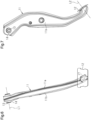
Fig. 6 is a front view of the vehicle pedal inFig. 1 . -
Fig. 7 is a side view of the vehicle pedal inFig. 1 . - A vehicle pedal according to one embodiment will now be described with reference to
Figs. 1 to 7 . - As shown in
Fig. 1 , the vehicle pedal includes ahollow arm 11 and apedal seat 12. Thehollow arm 11 is formed to have a specified length. Ahole 13 is formed in the upper end of thehollow arm 11. The upper end of thehollow arm 11 may be referred to as a second end. Asupport shaft 14 is inserted through thehole 13. Thesupport shaft 14 is fixed to the body of the vehicle. Thehollow arm 11 is pivotally supported by thesupport shaft 14. - The
pedal seat 12 is arranged at the lower end of thehollow arm 11, in other words, an end opposite to the upper end at which thehole 13 is formed. Thepedal seat 12 is welded to the lower end. The lower end of thehollow arm 11 may be referred to as a first end. A pedal force, generated when the user depresses the vehicle pedal, is applied to thepedal seat 12. When the pedal force of the user is applied to thepedal seat 12, the vehicle pedal is pivoted about a central axis L1 of thehole 13 and thesupport shaft 14. -
Fig. 2 shows thehollow arm 11 inFig. 1 taken along line II-II. As shown inFig. 2 , thehollow arm 11 is formed by two components, specifically, afirst component 11a and asecond component 11b. The first andsecond components second components first recess 15 and asecond recess 16 that extend in the longitudinal direction of the first andsecond components Fig. 2 ). Thehollow arm 11 is formed by joining the first andsecond components second recesses second components - As shown in
Fig. 3 , thehollow arm 11 includes an opening 17 at the lower end. Thehollow arm 11 includes awall 18 that forms the opening 17 at the lower end. Thewall 18 is an end region of a predetermined area of thehollow arm 11 in the longitudinal direction. Thewall 18 may be referred to as an opening forming portion. At the lower end of thewall 18, an open portion 18a is formed so that the inside of thehollow arm 11 is open downward. Thus, when the vehicle pedal is immersed in paint and lifted during coating, the paint easily enters thehollow arm 11 and is discharged from thehollow arm 11 through the open portion 18a. - The
wall 18 includes a firststraight portion 19, a secondstraight portion 20, afirst corner portion 21, and asecond corner portion 22. The first and secondstraight portions second recesses second components straight portions hollow arm 11. The first and secondstraight portions wall 18 is viewed from the direction facing theopening 17. The first and secondstraight portions straight portions second corner portions second recesses straight portions - The
pedal seat 12 shown inFig. 4 is welded to the first and secondstraight portions wall 18. However, thepedal seat 12 is not welded to the first andsecond corner portions wall 18. This is because it is difficult to secure space required for operations when thepedal seat 12 is welded to the first andsecond corner portions - As shown in
Figs. 3 and5 , afirst bead 23 and asecond bead 24 are arranged, respectively, on thewall 18 to extend across the ridges (vertices) of the first andsecond corner portions second beads opening 17 and located near the edges of the wall 18 (end surfaces forming opening 17). The first andsecond beads hollow arm 11. The first andsecond beads hollow arm 11. The first andsecond beads second corner portions pedal seat 12. -
Figs. 6 and 7 show the vehicle pedal inFig. 1 viewed from the front and the side, respectively. As shown inFig. 6 , the lower end of thehollow arm 11 at which thepedal seat 12 is arranged is offset from the upper end, where thehole 13 is formed, in a direction in which the central axis L1 of thehole 13 extends (rightward inFig. 6 ). This is because of limitations on the location where the vehicle pedal is attached to the vehicle body and the location of the vehicle seat on which the user is seated. The offset design allows the user to appropriately operate the vehicle pedal under such limitations. - As shown in
Fig. 7 , the lower end of thehollow arm 11 is curved so that a central axis L2 of the opening 17 (Fig. 6 ) is inclined toward the central axis L1 of the hole 13 (Fig. 6 ). In other words, the lower end of thehollow arm 11 is curved so that theopening 17 is oriented toward a side at which the upper end of thehollow arm 11 is located in relation to the lower end. - The vehicle pedal according to the present embodiment has the advantages described below.
- (1) When the user depresses the vehicle pedal, the pedal force of the user is applied to the
pedal seat 12. As a result, the load based on the pedal force acts on thepedal seat 12 to twist thepedal seat 12 relative to thehollow arm 11. The direction in which the load acting on thepedal seat 12 in this case is indicated by the arrow inFig. 4 . Such a load acts on thehollow arm 11 in a direction to widen the first andsecond corner portions wall 18. However, in the present embodiment, the first andsecond beads second corner portions wall 18 that may result from such a load. - (2) The first and
second beads wall 18 to extend across the ridges of the first andsecond corner portions second beads second corner portions second corner portions pedal seat 12. - (3) The lower end of the
hollow arm 11 at which thepedal seat 12 is arranged is offset from the upper end, where thehole 13 is formed, in the direction in which the central axis L1 of thehole 13 extends. Thus, when the load based on the pedal force of the user acts on thepedal seat 12, thepedal seat 12 easily twists relative to thehollow arm 11. As a result, the first andsecond corner portions wall 18 of thehollow arm 11 may be distorted and widened. However, in the present embodiment, thefirst bead 23 and thesecond bead 24 effectively restrict such distortion at the first andsecond corner portions - (4) The lower end of the
hollow arm 11, at which thepedal seat 12 is arranged, is curved so that the central axis L2 of theopening 17 is inclined toward the central axis L1 of thehole 13. To reduce the movement space of thehollow arm 11, it is preferred that the lower end of thehollow arm 11 at which thepedal seat 12 is arranged be reduced in size and the lower end of thehollow arm 11 be further curved. However, with thehollow arm 11 formed in this manner, when the load based on the pedal force of the user acts on thepedal seat 12, thepedal seat 12 easily twists relative to thehollow arm 11. As a result, the first andsecond corner portions wall 18 of thehollow arm 11 may be distorted and widened. However, in the present embodiment, thefirst bead 23 and thesecond bead 24 effectively restrict such distortion at the first andsecond corner portions - The above-described embodiment may be modified as follows. The above-described embodiment and the following modification can be combined if the combined modifications remain technically consistent with each other.
- The first and
second beads opening 17. - The first and
second beads wall 18. - The lower end of the
hollow arm 11 at which thepedal seat 12 is arranged does not need to be offset from the upper end, where thehole 13 is formed, in the direction in which the central axis L1 of thehole 13 extends.
Claims (5)
- A vehicle pedal, comprising:a hollow arm including two components with a specified length; anda pedal seat, whereinthe components each include a recess extending in a longitudinal direction of the corresponding component,the two components are joined with each other with the recesses being opposed to each other,the hollow arm includes a wall that forms an opening at a first end of the hollow arm in a longitudinal direction,the pedal seat is arranged at the first end and welded to the wall,the wall includes a straight portion and a corner portion,the straight portion is welded to the pedal seat, andthe corner portion includes a reinforced portion configured to restrict distortion of the corner portion when a pedal force from a user is applied to the pedal seat.
- The vehicle pedal according to claim 1, wherein the reinforced portion includes a bead arranged on the wall to extend across a ridge of the corner portion.
- The vehicle pedal according to claim 1 or 2, whereinthe hollow arm includes a second end at a side opposite to the first end,a hole, into which a support shaft that pivotally supports the hollow arm is inserted, is formed at the second end, andthe first end is offset from the second end in a direction in which a central axis of the hole extends.
- The vehicle pedal according to any one of claims 1 to 3, whereinthe hollow arm includes a second end at a side opposite to the first end,a hole, into which a support shaft that pivotally supports the hollow arm is inserted, is formed at the second end, andthe first end is curved so that a central axis of the opening is inclined toward a central axis of the hole.
- The vehicle pedal according to any one of claims 1 to 3, whereinthe hollow arm includes a second end at a side opposite to the first end,a hole, into which a support shaft that pivotally supports the hollow arm is inserted, is formed at the second end, andthe first end is curved so that the opening is oriented toward a side at which the second end is located in relation to the first end.
Applications Claiming Priority (2)
| Application Number | Priority Date | Filing Date | Title |
|---|---|---|---|
| JP2021167413A JP7509732B2 (en) | 2021-10-12 | 2021-10-12 | Vehicle pedals |
| PCT/JP2022/037811 WO2023063295A1 (en) | 2021-10-12 | 2022-10-11 | Vehicular pedal |
Publications (2)
| Publication Number | Publication Date |
|---|---|
| EP4383040A1 true EP4383040A1 (en) | 2024-06-12 |
| EP4383040A4 EP4383040A4 (en) | 2025-08-13 |
Family
ID=85987942
Family Applications (1)
| Application Number | Title | Priority Date | Filing Date |
|---|---|---|---|
| EP22880990.1A Pending EP4383040A4 (en) | 2021-10-12 | 2022-10-11 | PEDAL FOR VEHICLE |
Country Status (4)
| Country | Link |
|---|---|
| US (1) | US12372994B2 (en) |
| EP (1) | EP4383040A4 (en) |
| JP (1) | JP7509732B2 (en) |
| WO (1) | WO2023063295A1 (en) |
Family Cites Families (10)
| Publication number | Priority date | Publication date | Assignee | Title |
|---|---|---|---|---|
| JP4946551B2 (en) | 2007-03-19 | 2012-06-06 | マツダ株式会社 | Car door structure |
| JP5002083B2 (en) * | 2009-10-22 | 2012-08-15 | 豊田鉄工株式会社 | Vehicle operation pedal |
| JP5437144B2 (en) * | 2010-04-20 | 2014-03-12 | 株式会社エフテック | Pedal arm, pedal arm manufacturing apparatus, and pedal arm manufacturing method |
| ES2405154B1 (en) * | 2011-10-21 | 2014-08-04 | Batz, S.Coop. | Method of manufacturing a pedal for a motor vehicle, and pedal obtained according to the manufacturing method |
| JP6076845B2 (en) | 2013-06-28 | 2017-02-08 | 三菱自動車工業株式会社 | Pedal arm |
| JP6178707B2 (en) | 2013-11-21 | 2017-08-09 | 豊田鉄工株式会社 | Vehicle operation pedal |
| US9645600B2 (en) * | 2014-08-22 | 2017-05-09 | Ksr Ip Holdings Llc. | Two piece pedal arm |
| CN205311578U (en) | 2015-10-30 | 2016-06-15 | 上汽通用汽车有限公司 | Pedal arm reaches automobile pedal assembly, car including it |
| CN206958227U (en) | 2017-04-28 | 2018-02-02 | 厦门鸿凯电子科技有限公司 | A kind of automotive gear shifter electromagnet casing |
| CN211592522U (en) * | 2019-10-24 | 2020-09-29 | 东风(十堰)车身部件有限责任公司 | A lightweight pedal arm |
-
2021
- 2021-10-12 JP JP2021167413A patent/JP7509732B2/en active Active
-
2022
- 2022-10-11 WO PCT/JP2022/037811 patent/WO2023063295A1/en not_active Ceased
- 2022-10-11 EP EP22880990.1A patent/EP4383040A4/en active Pending
- 2022-10-11 US US18/579,366 patent/US12372994B2/en active Active
Also Published As
| Publication number | Publication date |
|---|---|
| US20240338048A1 (en) | 2024-10-10 |
| JP2023057749A (en) | 2023-04-24 |
| WO2023063295A1 (en) | 2023-04-20 |
| EP4383040A4 (en) | 2025-08-13 |
| US12372994B2 (en) | 2025-07-29 |
| JP7509732B2 (en) | 2024-07-02 |
Similar Documents
| Publication | Publication Date | Title |
|---|---|---|
| US9663148B2 (en) | Vehicle side section structure | |
| US20110304175A1 (en) | Skeleton structure of vehicle | |
| JP5811940B2 (en) | Body side structure | |
| JP4301269B2 (en) | Member member for vehicle | |
| CN106467137B (en) | Vehicle frame structure | |
| CN105849423A (en) | Bonded structure of dissimilar materials | |
| JP2017121881A (en) | Body front structure | |
| US20170036623A1 (en) | Bumper reinforcement | |
| JP2019048535A (en) | Body structure | |
| US9840132B2 (en) | Vehicle panel structure | |
| US11325647B2 (en) | Underbody structure of vehicle | |
| CN109746331B (en) | Joint structure for vehicle | |
| JP4957270B2 (en) | Body floor structure | |
| CN102971206B (en) | Vehicle body front structure | |
| US20240338048A1 (en) | Vehicular pedal | |
| US20180170441A1 (en) | Vehicle side structure | |
| CN105189264B (en) | The structure of the front stringer | |
| JP2013144496A (en) | vehicle | |
| CN105916713A (en) | Pipe-like reinforcement member for vehicle | |
| CN107225944B (en) | body structure | |
| CN215663679U (en) | Reinforcing structure for improving stability of automobile body of automobile front floor | |
| JP2022059489A (en) | Reinforcing structure of car body skeleton material | |
| JP2016107872A (en) | Vehicle front structure | |
| CN110198884B (en) | Vehicle body structure | |
| CN211943512U (en) | body side structure |
Legal Events
| Date | Code | Title | Description |
|---|---|---|---|
| STAA | Information on the status of an ep patent application or granted ep patent |
Free format text: STATUS: THE INTERNATIONAL PUBLICATION HAS BEEN MADE |
|
| PUAI | Public reference made under article 153(3) epc to a published international application that has entered the european phase |
Free format text: ORIGINAL CODE: 0009012 |
|
| STAA | Information on the status of an ep patent application or granted ep patent |
Free format text: STATUS: REQUEST FOR EXAMINATION WAS MADE |
|
| 17P | Request for examination filed |
Effective date: 20240308 |
|
| AK | Designated contracting states |
Kind code of ref document: A1 Designated state(s): AL AT BE BG CH CY CZ DE DK EE ES FI FR GB GR HR HU IE IS IT LI LT LU LV MC ME MK MT NL NO PL PT RO RS SE SI SK SM TR |
|
| DAV | Request for validation of the european patent (deleted) | ||
| DAX | Request for extension of the european patent (deleted) | ||
| REG | Reference to a national code |
Ref country code: DE Ref legal event code: R079 Free format text: PREVIOUS MAIN CLASS: G05G0001300000 Ipc: G05G0001500000 |
|
| A4 | Supplementary search report drawn up and despatched |
Effective date: 20250710 |
|
| RIC1 | Information provided on ipc code assigned before grant |
Ipc: G05G 1/50 20080401AFI20250704BHEP Ipc: G05G 1/44 20080401ALI20250704BHEP |