EP4382856A1 - Fastener bulb inspection device - Google Patents
Fastener bulb inspection device Download PDFInfo
- Publication number
- EP4382856A1 EP4382856A1 EP23214239.8A EP23214239A EP4382856A1 EP 4382856 A1 EP4382856 A1 EP 4382856A1 EP 23214239 A EP23214239 A EP 23214239A EP 4382856 A1 EP4382856 A1 EP 4382856A1
- Authority
- EP
- European Patent Office
- Prior art keywords
- bulb
- fastener
- inspection
- inspection sensor
- tolerance
- Prior art date
- Legal status (The legal status is an assumption and is not a legal conclusion. Google has not performed a legal analysis and makes no representation as to the accuracy of the status listed.)
- Pending
Links
Images





Classifications
-
- G—PHYSICS
- G06—COMPUTING OR CALCULATING; COUNTING
- G06T—IMAGE DATA PROCESSING OR GENERATION, IN GENERAL
- G06T7/00—Image analysis
- G06T7/0002—Inspection of images, e.g. flaw detection
- G06T7/0004—Industrial image inspection
- G06T7/001—Industrial image inspection using an image reference approach
-
- G—PHYSICS
- G01—MEASURING; TESTING
- G01B—MEASURING LENGTH, THICKNESS OR SIMILAR LINEAR DIMENSIONS; MEASURING ANGLES; MEASURING AREAS; MEASURING IRREGULARITIES OF SURFACES OR CONTOURS
- G01B11/00—Measuring arrangements characterised by the use of optical techniques
- G01B11/24—Measuring arrangements characterised by the use of optical techniques for measuring contours or curvatures
-
- G—PHYSICS
- G01—MEASURING; TESTING
- G01N—INVESTIGATING OR ANALYSING MATERIALS BY DETERMINING THEIR CHEMICAL OR PHYSICAL PROPERTIES
- G01N21/00—Investigating or analysing materials by the use of optical means, i.e. using sub-millimetre waves, infrared, visible or ultraviolet light
- G01N21/84—Systems specially adapted for particular applications
- G01N21/88—Investigating the presence of flaws or contamination
- G01N21/8851—Scan or image signal processing specially adapted therefor, e.g. for scan signal adjustment, for detecting different kinds of defects, for compensating for structures, markings, edges
-
- G—PHYSICS
- G01—MEASURING; TESTING
- G01N—INVESTIGATING OR ANALYSING MATERIALS BY DETERMINING THEIR CHEMICAL OR PHYSICAL PROPERTIES
- G01N21/00—Investigating or analysing materials by the use of optical means, i.e. using sub-millimetre waves, infrared, visible or ultraviolet light
- G01N21/84—Systems specially adapted for particular applications
- G01N21/88—Investigating the presence of flaws or contamination
- G01N21/95—Investigating the presence of flaws or contamination characterised by the material or shape of the object to be examined
- G01N21/9515—Objects of complex shape, e.g. examined with use of a surface follower device
-
- G—PHYSICS
- G06—COMPUTING OR CALCULATING; COUNTING
- G06T—IMAGE DATA PROCESSING OR GENERATION, IN GENERAL
- G06T7/00—Image analysis
- G06T7/10—Segmentation; Edge detection
- G06T7/13—Edge detection
-
- G—PHYSICS
- G06—COMPUTING OR CALCULATING; COUNTING
- G06T—IMAGE DATA PROCESSING OR GENERATION, IN GENERAL
- G06T2207/00—Indexing scheme for image analysis or image enhancement
- G06T2207/30—Subject of image; Context of image processing
- G06T2207/30108—Industrial image inspection
Definitions
- the present disclosure relates generally to fastening, and more specifically to a fastener bulb inspection device and methods of measuring a fastener bulb.
- various parts or components are connected to each other to form structures or substructures.
- Installation of mechanical fasteners such as, for example, blind fasteners or one-side fasteners, is generally conducted in order that the fastener is in flush alignment (i.e., no gaps) to the surface of the part.
- a blind fastener includes an internally threaded body and an externally threaded core bolt that passes through the internally threaded body.
- One end of the core bolt has an enlarged head, while the other end has an engaging portion.
- Rotation of the core bolt relative to the body causes axial movement of the core bolt in an outwardly direction from the body.
- Such axial movement thereby causes deformation of the body outwardly in a manner that forms a bulb that engages an inner surface of the part, thereby securing the blind fastener in place and attaching the parts to each other.
- a portion of the head of the core bolt typically fractures leaving a flush surface on the installed fastener head.
- the structural integrity of the connection between parts that is facilitated by the fastener may be compromised in the event the fastener has variability in its shape or size and/or the fastening hole of the part(s) to be fastened are offset due to machining tolerances. Inspection of installed fasteners such as, for example blind fasteners or one-side fasteners is often difficult, if not impossible due to the fact that the relatively tight access spaces and/or enclosed location of the fasteners make access to the "blind" side of the part(s) difficult and/or unavailable.
- the fastener bulb inspection device comprises a support providing a desired vertical position relative to an access hole of a structure with a fastener to be inspected; a gimbal connected to the support; and an inspection sensor connected to the gimbal by a telescopic arm.
- the support is telescopic.
- the device further comprises a cart connected to the support; and a rail configured to enable movement of the support relative to the structure.
- the rail is configured to be connected to a fixture supporting the structure or connected to the structure.
- the rail is configured to be connected to a manufacturing floor.
- the inspection sensor comprises a cup gauge for mechanical inspection.
- the inspection sensor comprises a camera.
- the device further comprises a computer system with an image comparator configured to identify an out of tolerance bulb in an image generated by the camera.
- the inspection sensor comprises a laser.
- the inspection sensor is one of a number of sensors connected to the telescopic arm, and wherein the number of sensors is further configured to perform alignment of the inspection sensor relative to the fastener.
- the device further comprises a communication device configured to receive position information from a fastening device for alignment of the inspection sensor relative to the fastener.
- the fastener bulb inspection device comprises a telescopic arm; a gimbal connected to a first side of the telescopic arm; and an inspection sensor connected to a second side of the telescopic arm, the inspection sensor configured to inspect a bulb of a fastener.
- the device further comprises a rail system, wherein the inspection sensor is connected to the rail system to translate relative to a structure comprising the fastener.
- the rail system is connected to a manufacturing floor.
- the rail system is connected to a fixture supporting the structure.
- the inspection sensor is part of a number of sensors connected to the telescopic arm, wherein the number of sensors comprise at least one of a borescope, a camera, a laser, LIDAR, a cup gauge, or a RFID detector.
- the number of sensors comprises at least one sensor configured to perform alignment of the inspection sensor.
- Yet another example of the present disclosure provides a method of inspecting a bulb of a fastener.
- An inspection sensor is placed into a confined space containing the bulb of the fastener.
- the inspection sensor is aligned relative to the bulb of the fastener.
- the bulb of the fastener is inspected. It is determined if the bulb of the fastener is within tolerance.
- aligning the inspection sensor comprises positioning the inspection sensor above the bulb of the fastener.
- aligning the inspection sensor comprises positioning the inspection sensor adjacent the bulb of the fastener so that a diameter and a height of the bulb is visible to the inspection sensor.
- aligning the inspection sensor comprises utilizing numerically controlled movement based on a designed location for the fastener.
- aligning the inspection sensor comprises identifying the bulb of the fastener within the confined space and moving the inspection sensor relative to the bulb based on the identifying.
- inspecting the bulb of the fastener comprises generating one of a photo or a video of the bulb of the fastener.
- determining if the bulb of the fastener is within tolerance comprises overlaying the photo of the bulb on a reference image.
- inspecting the bulb of the fastener comprises at least one of laser inspecting the bulb of the fastener or LIDAR inspecting the bulb of the fastener.
- aligning the inspection sensor relative to the bulb of the fastener comprises at least one of rotating the inspection sensor, extending the inspection sensor, or retracting the inspection sensor.
- placing the inspection sensor comprises extending a telescopic arm of a fastener bulb inspection device.
- rotating the inspection sensor comprises moving the telescopic arm using a gimbal connected to the telescopic arm.
- aligning the inspection sensor comprises moving the inspection sensor based on location data received from a fastening device.
- Yet another example of the present disclosure provides a method of inspecting a bulb of a fastener.
- An inspection sensor is placed adjacent a bulb of a fastener.
- An image of the bulb of the fastener is generated using the inspection sensor. It is determined if the bulb of the fastener is within tolerance by comparing the image to a reference image.
- comparing the image to the reference image comprises identifying a bulb edge in the image; and identifying if the bulb edge extends past a bulb boundary in the reference image.
- identifying the bulb edge comprises identifying at least one of a side of the bulb or a top of the bulb.
- determining if the bulb of the fastener is within tolerance comprises determining the bulb is out of tolerance if the top is above or below the bulb boundary.
- determining if the bulb of the fastener is within tolerance comprises determining the bulb is out of tolerance if the side is outside of the bulb boundary.
- the method further comprises generating an out of tolerance indication in response to a determination that the bulb of the fastener is outside of tolerance.
- comparing the image to the reference image comprises overlaying the reference image and the image.
- determining if the bulb of the fastener is within tolerance comprises determining at least one of if a diameter of the bulb is in tolerance or if a height of the bulb is in tolerance.
- the illustrative examples recognize and take into account one or more different considerations. For example, the illustrative examples recognize and take into account that operating robots, such as end effectors on robotic arms, within a manufacturing environment involves additional safety considerations. The illustrative examples recognize and take into account that human operators are prohibited from entering within a set distance of an area while a robot is active in the area. The illustrative examples recognize and take into account that to provide a safe operating condition for human operators, the operating area is typically a large footprint surrounding the robot. The illustrative examples recognize and take into account that it can be desirable to perform operations without the use of robotics to due to the safety requirements for robots within a manufacturing environment.
- the illustrative examples provide a fastener bulb inspection device.
- the fastener bulb inspection device of the illustrative examples is a mechanical system utilizing hard tooling instead of a robot.
- hard tooling fixturing By utilizing hard tooling fixturing, a smaller platform and a smaller operating space can be provided.
- additional operations can be performed within the manufacturing area.
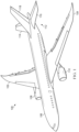
- Aircraft 100 has wing 102 and wing 104 attached to body 106. Aircraft 100 includes engine 108 attached to wing 102 and engine 110 attached to wing 104.
- Body 106 has tail section 112. Horizontal stabilizer 114, horizontal stabilizer 116, and vertical stabilizer 118 are attached to tail section 112 of body 106.
- Aircraft 100 is an example of an aircraft having fasteners to be inspected.
- at least one of body 106, wing 102, or wing 104 can have fasteners to be inspected within a confined space.
- FIG. 2 an illustration of a block diagram of a manufacturing environment is depicted in accordance with an illustrative example. Portions of aircraft 100 can be manufactured in manufacturing environment 200.
- structure 210 is a component of aircraft 100 of Figure 1 , such as portion of wing 102 or wing 104.
- Fastener bulb inspection device 202 is configured to inspect fastener 204 within confined space 206 of interior 208 of structure 210.
- Fastener bulb inspection device 202 comprises support 222, gimbal 226 connected to support 222, and inspection sensor 228 connected to gimbal 226 by telescopic 252 arm 250.
- gimbal 226 is depicted, any desirable universal joint can be provided.
- Gimbal 226 is configured to provide for movement about three axes.
- an alternative joint other than gimbal 226 is provided to allow for movement of telescopic 252 arm 250 about three axes.
- a rotational joint can connect inspection sensor 228 and telescopic 252 arm 250.
- a moveable joint connects inspection sensor 228 to telescopic 252 arm 250 so that inspection sensor 228 can move independently of telescopic 252 arm 250 and gimbal 226.
- Support 222 provides desired vertical position 224 relative to access hole 212 of structure 210 with fastener 204.
- support 222 can be referred to as vertical mount 232.
- support 222 is telescopic.
- cart 256 is connected to support 222. In some of these illustrative examples, cart 256 is connected to rail 258 of rail system 254. Rail 258 is configured to enable movement of support 222 relative to structure 210.
- rail 258 is configured to be connected to fixture 262 supporting structure 210. In other illustrative examples, rail 258 is configured to be connected to manufacturing floor 260.
- Fastener bulb inspection device 202 is used to determine if bulb 214 of fastener 204 is out of tolerance.
- bulb 214 is out of tolerance if the shape of bulb is not round.
- bulb 214 is out of tolerance if any diameter 218 of bulb 214 is greater than a set value.
- diameter 218 is determined.
- Inspection sensor 228 can take any desirable form.
- inspection sensor 228 can be at least one of borescope 238, camera 240, laser 242, lidar 244, or cup gauge 246.
- inspection sensor 228 comprises cup gauge 246 foe mechanical inspection.
- inspection sensor 228 comprises camera 240.
- inspection sensor 228 comprises laser 242.
- Inspection sensor 228 is configured to generate data concerning bulb 214.
- the inspection data can comprise one or more of image data, measurement data, and spatial proximity/position data of fastener 204. The inspection data can be used to determine at least one of circumference 216, diameter 218, or edge 220 of bulb 214 of fastener 204.
- Camera 240 can generate image 241 of fastener 204 with bulb 214.
- inspection sensor 228 comprises camera 240, and inspection sensor 228 is positioned adjacent bulb 214 of so that diameter 218 and height 217 of bulb 214 is visible to inspection sensor 228.
- camera 240 When camera 240 is adjacent fastener 204, camera 240 generates image 241 of fastener 204.
- a comparison of image 241 and reference image 281 is conducted.
- image 241 is overlaid with reference image 281.
- bulb edge 243 is identified.
- Bulb edge 243 comprises side 247 and top 245.
- bulb edge 243 is compared to bulb boundary 283 of reference image 281.
- side 247 is compared to bulb boundary 283 to determine if diameter 218 is in tolerance.
- side 247 comprises one point in image 241.
- side 247 comprises multiple points in image 241.
- side 247 comprises a line or arc of bulb edge 243.
- top 245 is compared to bulb boundary 283 to determine if height 217 is in tolerance. In some illustrative examples, top 245 comprises one point in image 241. In some illustrative examples, top 245 comprises multiple points in image 241. In some illustrative examples, top 245 comprises a line or arc of bulb edge 243.
- Image comparator 279 can receive image 241 and analyze image 241 to determine if bulb 214 is in tolerance. In some illustrative examples, image comparator 279 can overlay image 241 over reference image 281. In some illustrative examples, image comparator 279 performs image recognition to identify bulb edge 243. In some illustrative examples, image comparator 279 performs image recognition to identify at least one of top 245 or side 247.
- bulb boundary 283 comprises a pictoral representation of acceptable ranges of values for diameter 218 and height 217. In some illustrative examples, if bulb edge 243 is positioned within bulb boundary 283, bulb 214 is in tolerance. In some illustrative examples, if at least a portion of bulb edge 243 extends outside of bulb boundary 283, at least one of diameter 218 or height 217 of fastener 204 is out of tolerance.
- utilizing image comparator 279 and image 241 is a go-no-go analysis by image comparison. If image comparator 279 determines that bulb edge 243 extends outside of bulb boundary 283, then bulb 214 can be identified as out of tolerance.
- a direct go-no-go measurement is conducted.
- cup gauge 246 can be used. Cup gauge 246 is used for mechanical inspection.
- image data is generated and then analyzed to determine measurements of bulb 214.
- camera 240 or borescope 238 generates image data to be analyzed for measurements of bulb 214.
- Number of sensors 236 comprises one or more sensors configured to detect, determine, assess, monitor, measure, quantify, and/or sense information about fastener 204.
- sensor means any device, component, and/or system that is to perform one or more of detecting, determining, assessing, monitoring, measuring, quantifying, and sensing one or more things in manufacturing environment 200.
- inspection sensor 228 can also be used to align inspection sensor 228 relative to fastener 204.
- image data from camera 240 can be used to align inspection sensor 228 such that inspection sensor 228 is over bulb 214.
- inspection sensor 228 it is desirable for inspection sensor 228 to provide a "top down" view of bulb 214.
- inspection sensor 228 is one of number of sensors 236 connected to telescopic 252 arm 250, and wherein number of sensors 236 is further configured to perform alignment of inspection sensor 228 relative to fastener 204.
- RFID detector 248 can be used for alignment 264 of inspection sensor 228.
- Alignment 264 of inspection sensor 228 can be a single step or multi-step.
- alignment 264 includes a macro alignment followed by a micro alignment.
- alignment 264 includes an initial movement of fastener bulb inspection device 202 based on design data or communicated data from manufacturing and then adjusted based on data received from number of sensors 236.
- alignment 264 is performed using data received at communication device 280.
- alignment 264 is performed using data received from a drill (not depicted).
- alignment 264 is performed using data received from fastening device 274.
- Communication device 280 can be present in any desirable location. In some illustrative examples, communication device 280 is present within computer system 278. In some illustrative examples, computer system 278 can be present on cart 256. Communication device 280 is configured to receive position information from fastening device 274 for alignment of inspection sensor 228 relative to the fastener 204.
- alignment 264 of inspection sensor 228 is numerically controlled 266.
- Alignment 264 of inspection sensor 228 can use numerically controlled 266 movements based a designed location for fastener 204.
- inspection of fastener 204 can be performed after alignment 264 the inspection sensor based on the designed location.
- the designed location provides an initial location for alignment of inspection sensor 228.
- alignment 264 includes communication between fastener bulb inspection device 202 and fastening device 274 regarding an actual position of fastener 204 within manufacturing environment.
- number of sensors 236 perform further alignment 264 based on a detected location of fastener 204 to position number of sensors 236 relative to fastener 204 prior to inspecting fastener 204.
- alignment 264 of inspection sensor 228 relative to bulb 214 of fastener 204 comprises at least one of rotating inspection sensor 228, extending inspection sensor 228, or retracting inspection sensor 228.
- Fastener bulb inspection device 202 comprises telescopic 252 arm 250, gimbal 226 connected to a first side of telescopic 252 arm 250, and inspection sensor 228 connected to a second side of telescopic 252 arm 250, inspection sensor 228 configured to inspect bulb 214 of fastener 204.
- Gimbal 226 allows for rotating 234 inspection sensor 228.
- Telescopic 252 arm 250 allows for extending and retracting inspection sensor 228 in confined space 206 of interior 208 of structure 210.
- alignment 264 of inspection sensor 228 comprises positioning inspection sensor 228 above bulb 214. In some illustrative examples, alignment 264 of inspection sensor 228 comprises positioning inspection sensor 228 such that the whole of bulb 214 is visible to inspection sensor 228. Alignment 264 of inspection sensor 228 is performed such that inspection sensor 228 can inspect the whole of bulb 214.
- fastener bulb inspection device further comprises rail system 254, wherein inspection sensor 228 is connected to rail system 254 to translate relative to structure 210 comprising fastener 204.
- rail system 254 is connected to manufacturing floor 260.
- rail system 254 is connected to fixture 262 supporting structure 210 or connected to structure 210.
- cart 256 could run over a skin or other surface of structure 210 if fastener bulb inspection device 202 is light enough to travel on structure 210 without undesirably affecting structure 210.
- inspection sensor 228 is part of number of sensors 236 connected to telescopic 252 arm 250.
- number of sensors 236 comprise at least one of borescope 238, camera 240, laser 242, LIDAR 244, cup gauge 246, or RFID detector 248.
- Number of sensors 236 is configured for at least one of manual control by a user or automatic control by computer system 278 to detect, determine, assess, monitor, measure, quantify, and/or sense information about fastener 204.
- the inspection data can comprise one or more of image data, measurement data, and spatial proximity/position data of fastener 204.
- bulb 214 is evaluated by conducting a comparison between the inspection data from inspection sensor 228 and a predetermined threshold measurement.
- Fastener 204 is one of number of blind fasteners 276 in confined space 206.
- Inspection sensor 228 can be moved within confined space to inspect each of number of blind fasteners 276.
- inspection sensor 228 is placed within confined space 206 relative to a respective fastener of number of blind fasteners 276.
- computer system 278 can be used to store at least one of inspection data from inspection sensor 228 or predetermined tolerance values. In some illustrative examples, computer system 278 can numerically control operation of fastener bulb inspection device 202.
- FIG. 2 The illustration of manufacturing environment 200 in Figure 2 is not meant to imply physical or architectural limitations to the manner in which an illustrative example may be implemented. Other components in addition to or in place of the ones illustrated may be used. Some components may be unnecessary. Also, the blocks are presented to illustrate some functional components. One or more of these blocks may be combined, divided, or combined and divided into different blocks when implemented in an illustrative example. For example, although fastener bulb inspection device 202 is depicted as connected to rail system 254, in some illustrative examples, rail system 254 is optional. In some illustrative examples, fastener bulb inspection device 202 is connected to cart 256 that is manual. In some illustrative examples, cart 256 can be pulled or pushed by an operator within manufacturing environment 200.
- number of sensors 236 comprises one or more sensors including, but not limited to, infrared sensors, proximity/position sensors, laser sensors, ultraviolet sensors, heat sensors, and image sensors (e.g., cameras).
- inspection data can be collected for other types of fasteners or other types of features.
- inspection data can comprise any information corresponding to one or more structural features (e.g., blind bulb, nut, collar, pin protrusion, thin sleeve protrusion, a fastener head, a nut-and-pin protrusion, a swaged collar, a bracket, an insert, a clip, a trimmed or machined feature, etc.) and spatial relationship(s) between the fastener F and the inspection environment E that falls within the scope of this disclosure.
- the inspection data is to correspond to the dimensions (e.g., diameter, thickness, and/or height) of one or more structural features, such as, for example, a retention feature or bulb feature of fastener 204.
- gimbal 226 is depicted as connecting telescopic 252 arm 250 and support 222, in some other non-depicted illustrative examples, gimbal 226 can connect inspection sensor 228 to telescopic 252 arm 250.
- a gimbal can be present when access hole 212 is sufficiently large enough to accommodate a gimbal to extend through access hole 212.
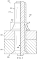
- FIG. 3 an illustration of a cross-sectional view of a fastener system after installation is depicted in accordance with an illustrative example.
- fastener 301 is depicted in installed state 314.
- Fastener is a physical implementation of fastener 204 of Figure 2 .
- Fastener 301 can be used to join components in aircraft 100.
- fastener 301 can be used in one of body 106, wing 102, or wing 104.
- Fastener 301 can be inspected by fastener bulb inspection device 202 of Figure 2 after installation.
- fastener 301 joins component 302 and component 304.
- Core 308 of fastener 301 is placed through surface 306 to engage body 310 of fastener 301.
- Core 308 has been rotated to engage and deform body 310 outwardly forming bulb 313.
- bulb 313 has diameter 312.
- diameter 312 is a single measurement from a single view, it is desirable to inspect the whole of bulb 313 so that any out of tolerance conditions can be detected.
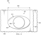
- View 400 is a top view of fastener 301 of Figure 3 .
- bulb 313 has non-symmetrical shape 404.
- diameter 406 of bulb 313 is out of tolerance.
- View 500 is a view of structure 502 in a manufacturing environment.
- structure 502 comprises fasteners 514 to be inspected by fastener bulb inspection device 518.
- Fastener bulb inspection device 518 is a physical implementation of fastener bulb inspection device 202 of Figure 2 .
- Structure 502 comprises rib 504, rib 506, spar 508, and spar 510 forming confined space 512.
- Number of fasteners 514 are present in confined space 512 of structure 502. Number of fasteners 514 are not visible outside of structure 502 due to the skin (not depicted) forming confined space 512.
- Fastener bulb inspection device 518 is configured to inspect number of fasteners 514 within confined space 512. More specifically, fastener bulb inspection device 518 is configured to inspect at least one of the size or shape of the bulbs of number of fasteners 514. In some illustrative examples, fastener bulb inspection device 518 measures a set number of diameters of the bulbs of number of fasteners 514. In some illustrative examples, fastener bulb inspection device 518 determines if the bulbs of number of fasteners 514 are sufficiently symmetrical. In some illustrative examples, fastener bulb inspection device 518 determines if any of the bulbs of number of fasteners 514 are out of tolerance for size.
- Fastener bulb inspection device 518 comprises support 520 providing a desired vertical position relative to access hole 528 of structure 502.
- Gimbal 522 is connected to support 520.
- Gimbal 522 enables rotational movement of telescopic arm 526 relative to support 520.
- Inspection sensor 524 is connected to gimbal 522 by telescopic arm 526.
- Inspection sensor 524 is configured to inspect at least one of the size or shape of the bulb of fastener 514. Inspection sensor 524 takes any desirable form. In some illustrative examples, inspection sensor 524 comprises a camera. In some illustrative examples, inspection sensor 524 comprises a laser.
- support 520 is telescopic. By extending support 520, a vertical position of telescopic arm 526 is changed. The vertical position of telescopic arm 526 can also be adjusted using gimbal 522.
- fastener bulb inspection device 518 comprises a rail system, where inspection sensor 524 is connected to the rail system to translate relative to structure 502 comprising fastener 514.
- the rail system is connected to the manufacturing floor.
- support 520 is connected to cart 530.
- Cart 530 is connected to rail 532.
- Rail 532 is configured to enable movement of support 520 relative to structure 502.
- rail 532 is configured to be connected to a manufacturing floor.
- cart 530 can move along rail 532 for fastener bulb inspection device 518 to be positioned relative to another access hole, such as access hole 534.
- inspection sensor 524 can be sent through access hole 534 to inspect bulbs of fasteners within an additional confined space in structure 502.
- gimbal 522 is connected to a first side of telescopic arm 526, and inspection sensor 524 is connected to a second side of telescopic arm 526. Inspection sensor 524 is configured to inspect a bulb of fastener 514.
- inspection sensor 524 is part of a number of sensors connected to telescopic arm 526.
- the number of sensors can comprise any desirable quantity and type of sensors to allow for alignment of inspection sensor 524 and inspection of fastener 514.
- the number of sensors comprise at least one of a borescope, a camera, a laser, LIDAR, a cup gauge, or a RFID detector.
- View 600 is a perspective view of structure 602 with fasteners (not depicted) to be inspected.
- skin 603 of structure 602 is illustrated.
- access to a confined space within structure 602 is possible through access hole 606 of spar 604.
- fasteners in structure 602 are not visible from outside of structure 602. Further, if a fastener is visible from outside of structure 602, measurement of the fastener is not possible from outside of structure 602.
- fastener bulb inspection device 609 is movable relative to access hole 606 on rail 608.
- Fastener bulb inspection device 609 is a physical implementation of fastener bulb inspection device 202 of Figure 2 .
- rail 608 is connected to fixture 611 supporting structure 602. With rail 608 connected to fixture 611, support 612 can extend a shorter distance to reach access hole 606 than if cart 610 traveled on a rail connected to the manufacturing floor, as in Figure 5 .
- a telescopic arm 614 connected to gimbal 616 has been extended through access hole 606 to move number of sensors 618 within the confined space of structure 602 to inspect the fasteners (not depicted).
- fastener bulb inspection device 609 comprises a rail system, where an inspection sensor of number of sensors 618 is connected to the rail system to translate relative to structure 602 comprising the fastener.
- the rail system is connected to a fixture supporting the structure.
- support 612 is connected to cart 610.
- Cart 610 is connected to rail 608.
- Rail 608 is configured to enable movement of support 612 relative to structure 602.
- rail 608 is configured to be connected to a fixture supporting the structure.
- Fastener bulb inspection device 701 is a physical implementation of fastener bulb inspection device 202 of Figure 2 .
- View 700 is a view of fastener bulb inspection device 701 moving relative to number of fasteners 702 to inspect number of fasteners 702.
- telescopic arm 708 can be extended or retracted.
- telescopic arm 708 can be moved about gimbal 706.
- support 704 can be extended or retracted.
- number of sensors 710 can be positioned over a desired fastener of number of fasteners 702.
- number of sensors 710 can be moved in X, Y, and Z directions. Additionally, number of sensors 710 can be rotated by gimbal 706.
- Fastener bulb inspection device 701 is a physical implementation of fastener bulb inspection device 202 of Figure 2 .
- support 802 is a telescopic support.
- Gimbel 804 is connected to support 802 and telescopic arm 806.
- inspection sensor 808 comprises cup gauge 809 for mechanical inspection.
- Cup gauge 809 allows for detecting if any diameter of a bulb of a fastener is outside of tolerance. If cup gauge 809 does not fit over the bulb of the fastener, at least one portion of the bulb is out of tolerance.
- Cup gauge 809 is capable of detecting asymmetric bulbs, such as non-circular bulbs that have a portion that is out of tolerance.
- fastener bulb inspection device 202 is connected to cart 810 that is moved independently of a rail system.
- cart 810 has wheels 812 and handle 814 that allow cart 810 to be maneuvered independently of rails within a manufacturing environment.
- fastener bulb inspection device 202 can be manually maneuvered by an operator within the manufacturing environment.
- Computer system 816 is present on cart 810.
- Computer system 816 is configured to record inspection data generated by inspection sensor 808 during inspection of bulbs.
- movement of fastener bulb inspection device 800 is controlled by computer system 816.
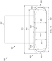
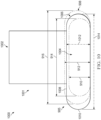
- image 902 of bulb 904 is compared to reference image 905.
- Image 902 can be an implementation of image 241 of Figure 2 .
- Image 902 can be an image of bulb 214 of Figure 2 .
- Bulb 904 can be an implementation of bulb 313 of Figures 3 and 4 .
- Image 902 can be an image of any of fasteners 514 of Figure 5 .
- Image 902 can be generated by number of sensors 618 of Figure 6 .
- Image 902 can be generated by number of sensors 710 of Figure 7 .
- comparing image 902 to reference image 905 comprises identifying bulb edge 906 in image 902. In some illustrative examples, comparing image 902 to reference image 905 comprises identifying if the bulb edge 906 extends past bulb boundary 908 in reference image 905.
- Bulb boundary 908 comprises minimum height 910 and maximum height 912 for a bulb to be in tolerance. Bulb boundary 908 comprises minimum diameter 914 and maximum diameter 916 for a bulb to be in tolerance.
- bulb edge 906 is positioned within bulb boundary 908. Accordingly, bulb 904 can be determined to be in tolerance.
- identifying bulb edge 906 comprises identifying at least one of side 920 of bulb 904 or top 918 of bulb 904. In some illustrative examples, determining if bulb 904 of fastener 907 is within tolerance comprises determining bulb 904 is out of tolerance if top 918 is above or below bulb boundary 908. In some illustrative examples, determining if bulb 904 of fastener 907 is within tolerance comprises determining bulb 904 is out of tolerance if side 920 is outside of bulb boundary 908. In some illustrative examples, determining if bulb 904 of fastener 907 is within tolerance comprises determining bulb 904 is out of tolerance if any portion of bulb edge 906 extends outside of bulb boundary 908.
- comparing image 902 to reference image 905 comprises overlaying reference image 905 and image 902.
- determining if the bulb of the fastener is within tolerance comprises determining at least one of if diameter 922 of bulb 904 is in tolerance or if a height 921 of bulb 904 is in tolerance.
- bulb edge 906 is within bulb boundary 908.
- bulb 904 is in tolerance.
- View 1000 is a view of image 1002 overlaid with reference image 905.
- bulb 1004 of fastener 1001 has bulb edge 1006.
- Bulb edge 1006 has top 1008 and side 1010.
- height 1012 of bulb 1004 is in tolerance.
- diameter 1014 of bulb 1004 is out of tolerance.
- bulb edge 1006 extends outside of bulb boundary 908.
- side 1010 of bulb edge 1006 is outside of bulb boundary 908.
- comparing bulb edge 1006 of image 1002 to bulb boundary 908 of reference image 905 identifies an out of tolerance condition.
- Method 1100 can be performed using fastener bulb inspection device 202 of Figure 2 .
- Method 1100 can be performed to inspect fastener 301 of Figures 3 and 4 after installation.
- Method 1100 can be performed using fastener bulb inspection device 518 of Figure 5 .
- Method 1100 can be performed using fastener bulb inspection device 609 of Figure 6 .
- Method 1100 can be performed using fastener bulb inspection device 703 of Figure 7 .
- Method 1100 can be performed using fastener bulb inspection device 800 of Figure 8 .
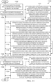
- Method 1100 places an inspection sensor into a confined space containing the bulb of the fastener (operation 1102).
- Method 1100 aligns the inspection sensor relative to the bulb of the fastener (operation 1104).
- Method 1100 inspects the bulb of the fastener (operation 1106).
- Method 1100 determines if the bulb of the fastener is out of tolerance (operation 1108). Afterwards, method 1100 terminates.
- the bulb of the fastener can be inspected after fastening operations are completed and the bulb is formed.
- the bulb of the fastener can be inspected during forming of the bulb. For example, images or videos of the bulb can be taken as the bulb is formed.
- aligning the inspection sensor comprises moving the inspection sensor based on location data received from a fastening device (operation 1109). In some illustrative examples, aligning the inspection sensor comprises positioning the inspection sensor above the bulb of the fastener (operation 1110). In some illustrative examples, aligning the inspection sensor comprises positioning the inspection sensor so that the whole of the bulb is visible to the inspection sensor. In some illustrative examples, aligning the inspection sensor comprises positioning the inspection sensor adjacent the bulb of the fastener so that a diameter and a height of the bulb is visible to the inspection sensor (operation 1111).
- aligning the inspection sensor comprises utilizing numerically controlled movement based on a designed location for the fastener (operation 1112).
- inspection of the fastener can be performed after aligning the inspection sensor based on the designed location.
- the designed location provides an initial location for aligning the inspection sensor.
- the number of sensors after moving to the initial location, perform a further alignment based on a detected location of the fastener to position the number of sensors relative to the fastener prior to inspecting the fastener.
- aligning the inspection sensor comprises identifying the bulb of the fastener within the confined space and moving the inspection sensor relative to the bulb based on the identifying (operation 1114). Identifying the bulb can take any desirable form. In some illustrative examples, the bulb is identified using at least one of a camera, a borescope, a UV sensor, a cup gauge, or other desirable sensor.
- aligning the inspection sensor relative to the bulb of the fastener comprises at least one of rotating the inspection sensor, extending the inspection sensor, or retracting the inspection sensor (operation 1116).
- placing the inspection sensor comprises extending a telescopic arm of a fastener bulb inspection device (operation 1118).
- rotating the inspection sensor comprises moving the telescopic arm using a gimbal connected to the telescopic arm (operation 1120) .
- inspecting the bulb of the fastener comprises generating one of a photo or a video of the bulb of the fastener (operation 1122). In some illustrative examples, inspecting the bulb of the fastener comprises at least one of laser inspecting the bulb of the fastener or LIDAR inspecting the bulb of the fastener (operation 1124). In some illustrative examples, determining if the bulb of the fastener is within tolerance comprises overlaying the photo of the bulb on a reference image (operation 1126).
- Method 1200 can be performed using fastener bulb inspection device 202 of Figure 2 .
- Method 1200 can be performed to inspect fastener 301 of Figures 3 and 4 after installation.
- Method 1200 can be performed using fastener bulb inspection device 518 of Figure 5 .
- Method 1200 can be performed using fastener bulb inspection device 609 of Figure 6 .
- Method 1200 can be performed using fastener bulb inspection device 703 of Figure 7 .
- Method 1200 can be performed using fastener bulb inspection device 800 of Figure 8 .
- Method 1200 can be performed using an overlay such as view 900 of Figure 9 .
- Method 1200 can be performed using an overlay such as view 1000 of Figure 10 .
- Method 1200 places an inspection sensor adjacent a bulb of a fastener (operation 1202).
- Method 1200 generates an image of the bulb of the fastener using the inspection sensor (operation 1204).
- Method 1200 determines if the bulb of the fastener is within tolerance by comparing the image to a reference image (operation 1206). Afterwards, method 1200 terminates.
- comparing the image to the reference image comprises identifying a bulb edge in the image (operation 1210), and identifying if the bulb edge extends past a bulb boundary in the reference image (operation 1212). In some illustrative examples, identifying the bulb edge comprises identifying at least one of a side of the bulb or a top of the bulb (operation 1214).
- determining if the bulb of the fastener is within tolerance comprises determining the bulb is out of tolerance if the top is above or below the bulb boundary (operation 1216). In some illustrative examples, determining if the bulb of the fastener is within tolerance comprises determining the bulb is out of tolerance if the side is outside of the bulb boundary (operation 1218).
- method 1200 generates an out of tolerance indication in response to a determination that the bulb of the fastener is outside of tolerance (operation 1220).
- comparing the image to the reference image comprises overlaying the reference image and the image (operation 1222).
- determining if the bulb of the fastener is within tolerance comprises determining at least one of if a diameter of the bulb is in tolerance or if a height of the bulb is in tolerance (operation 1224).
- the phrase "at least one of,” when used with a list of items, means different combinations of one or more of the listed items may be used and only one of each item in the list may be needed.
- “at least one of item A, item B, or item C” may include, without limitation, item A, item A and item B, or item B. This example also may include item A, item B, and item C or item B and item C. Of course, any combinations of these items may be present.
- "at least one of” may be, for example, without limitation, two of item A; one of item B; and ten of item C; four of item B and seven of item C; or other suitable combinations.
- the item may be a particular object, thing, or a category. In other words, at least one of means any combination items and number of items may be used from the list but not all of the items in the list are required.
- each block in the flowcharts or block diagrams may represent at least one of a module, a segment, a function, or a portion of an operation or step.
- the function or functions noted in the blocks may occur out of the order noted in the figures.
- two blocks shown in succession may be executed substantially concurrently, or the blocks may sometimes be performed in the reverse order, depending upon the functionality involved.
- other blocks may be added in addition to the illustrated blocks in a flowchart or block diagram. Some blocks may be optional.
- operation 1110 through operation 1124 may be optional.
- aircraft manufacturing and service method 1300 may be described in the context of aircraft manufacturing and service method 1300 as shown in Figure 13 and aircraft 1400 as shown in Figure 14 .
- Figure 13 an illustration of an aircraft manufacturing and service method in a form of a block diagram is depicted in accordance with an illustrative example.
- aircraft manufacturing and service method 1300 may include specification and design 1302 of aircraft 1400 in Figure 14 and material procurement 1304.
- aircraft 1400 During production, component and subassembly manufacturing 1306 and system integration 1308 of aircraft 1400 takes place. Thereafter, aircraft 1400 may go through certification and delivery 1310 in order to be placed in service 1312. While in service 1312 by a customer, aircraft 1400 is scheduled for routine maintenance and service 1314, which may include modification, reconfiguration, refurbishment, or other maintenance and service.
- Each of the processes of aircraft manufacturing and service method 1300 may be performed or carried out by a system integrator, a third party, and/or an operator.
- the operator may be a customer.
- a system integrator may include, without limitation, any number of aircraft manufacturers and major-system subcontractors
- a third party may include, without limitation, any number of vendors, subcontractors, and suppliers
- an operator may be an airline, a leasing company, a military entity, a service organization, and so on.
- aircraft 1400 is produced by aircraft manufacturing and service method 1300 of Figure 13 and may include airframe 1402 with plurality of systems 1404 and interior 1406.
- systems 1404 include one or more of propulsion system 1408, electrical system 1410, hydraulic system 1412, and environmental system 1414. Any number of other systems may be included.
- Apparatuses and methods embodied herein may be employed during at least one of the stages of aircraft manufacturing and service method 1300.
- One or more illustrative examples may be manufactured or used during at least one of component and subassembly manufacturing 1306, system integration 1308, in service 1312, or maintenance and service 1314 of Figure 13 .
- Fastener bulb inspection device 202 of Figure 2 can be used during component and subassembly manufacturing 1306, system integration 1308, or maintenance and service 1314 of Figure 13 to inspect bulbs of fasteners.
- Fastener bulb inspection device 202 of Figure 2 can be used to inspect fastener bulbs in at least one of airframe 1402 or interior 1406.
- Method 1100 can be performed to inspect portions of airframe 1402 or interior 1406.
- Method 1100 can be performed during at least one of component and subassembly manufacturing 1306, system integration 1308, or maintenance and service 1314 of Figure 13 .
- the illustrative examples provide for bulb inspection of fasteners within confined spaces without the use of robotic systems.
- a fastener bulb inspection device utilizing hard tooling is provided.
- the fastener bulb inspection device provides for inspection of the whole bulb of the fastener.
Landscapes
- Engineering & Computer Science (AREA)
- Physics & Mathematics (AREA)
- General Physics & Mathematics (AREA)
- Computer Vision & Pattern Recognition (AREA)
- Theoretical Computer Science (AREA)
- Life Sciences & Earth Sciences (AREA)
- Health & Medical Sciences (AREA)
- Chemical & Material Sciences (AREA)
- Analytical Chemistry (AREA)
- Biochemistry (AREA)
- General Health & Medical Sciences (AREA)
- Immunology (AREA)
- Pathology (AREA)
- Quality & Reliability (AREA)
- Signal Processing (AREA)
- Automatic Assembly (AREA)
Abstract
Description
- The present disclosure relates generally to fastening, and more specifically to a fastener bulb inspection device and methods of measuring a fastener bulb.
- In a manufacturing environment, such as, for example, the manufacture of aircraft, various parts or components are connected to each other to form structures or substructures. Installation of mechanical fasteners such as, for example, blind fasteners or one-side fasteners, is generally conducted in order that the fastener is in flush alignment (i.e., no gaps) to the surface of the part.
- A blind fastener includes an internally threaded body and an externally threaded core bolt that passes through the internally threaded body. One end of the core bolt has an enlarged head, while the other end has an engaging portion. Rotation of the core bolt relative to the body causes axial movement of the core bolt in an outwardly direction from the body. Such axial movement thereby causes deformation of the body outwardly in a manner that forms a bulb that engages an inner surface of the part, thereby securing the blind fastener in place and attaching the parts to each other. When installing a blind fastener, a portion of the head of the core bolt typically fractures leaving a flush surface on the installed fastener head.
- The structural integrity of the connection between parts that is facilitated by the fastener may be compromised in the event the fastener has variability in its shape or size and/or the fastening hole of the part(s) to be fastened are offset due to machining tolerances. Inspection of installed fasteners such as, for example blind fasteners or one-side fasteners is often difficult, if not impossible due to the fact that the relatively tight access spaces and/or enclosed location of the fasteners make access to the "blind" side of the part(s) difficult and/or unavailable.
- Therefore, it would be desirable to have a method and apparatus that takes into account at least some of the issues discussed above, as well as other possible issues.
- An example of the present disclosure provides a fastener bulb inspection device. The fastener bulb inspection device comprises a support providing a desired vertical position relative to an access hole of a structure with a fastener to be inspected; a gimbal connected to the support; and an inspection sensor connected to the gimbal by a telescopic arm.
- Optionally, the support is telescopic.
- Optionally, the device further comprises a cart connected to the support; and a rail configured to enable movement of the support relative to the structure. Preferably, the rail is configured to be connected to a fixture supporting the structure or connected to the structure. Preferably, the rail is configured to be connected to a manufacturing floor.
- Optionally, the inspection sensor comprises a cup gauge for mechanical inspection.
- Optionally, the inspection sensor comprises a camera. Preferably, the device further comprises a computer system with an image comparator configured to identify an out of tolerance bulb in an image generated by the camera.
- Optionally, the inspection sensor comprises a laser.
- Optionally, the inspection sensor is one of a number of sensors connected to the telescopic arm, and wherein the number of sensors is further configured to perform alignment of the inspection sensor relative to the fastener.
- Optionally, the device further comprises a communication device configured to receive position information from a fastening device for alignment of the inspection sensor relative to the fastener.
- Another example of the present disclosure provides a fastener bulb inspection device. The fastener bulb inspection device comprises a telescopic arm; a gimbal connected to a first side of the telescopic arm; and an inspection sensor connected to a second side of the telescopic arm, the inspection sensor configured to inspect a bulb of a fastener.
- Optionally, the device further comprises a rail system, wherein the inspection sensor is connected to the rail system to translate relative to a structure comprising the fastener. Preferably, the rail system is connected to a manufacturing floor. Preferably, the rail system is connected to a fixture supporting the structure.
- Optionally, the inspection sensor is part of a number of sensors connected to the telescopic arm, wherein the number of sensors comprise at least one of a borescope, a camera, a laser, LIDAR, a cup gauge, or a RFID detector. Preferably, the number of sensors comprises at least one sensor configured to perform alignment of the inspection sensor.
- Yet another example of the present disclosure provides a method of inspecting a bulb of a fastener. An inspection sensor is placed into a confined space containing the bulb of the fastener. The inspection sensor is aligned relative to the bulb of the fastener. The bulb of the fastener is inspected. It is determined if the bulb of the fastener is within tolerance.
- Optionally, aligning the inspection sensor comprises positioning the inspection sensor above the bulb of the fastener.
- Optionally, aligning the inspection sensor comprises positioning the inspection sensor adjacent the bulb of the fastener so that a diameter and a height of the bulb is visible to the inspection sensor.
- Optionally, aligning the inspection sensor comprises utilizing numerically controlled movement based on a designed location for the fastener.
- Optionally, aligning the inspection sensor comprises identifying the bulb of the fastener within the confined space and moving the inspection sensor relative to the bulb based on the identifying.
- Optionally, inspecting the bulb of the fastener comprises generating one of a photo or a video of the bulb of the fastener. Preferably, determining if the bulb of the fastener is within tolerance comprises overlaying the photo of the bulb on a reference image.
- Optionally, inspecting the bulb of the fastener comprises at least one of laser inspecting the bulb of the fastener or LIDAR inspecting the bulb of the fastener.
- Optionally, aligning the inspection sensor relative to the bulb of the fastener comprises at least one of rotating the inspection sensor, extending the inspection sensor, or retracting the inspection sensor. Preferably, placing the inspection sensor comprises extending a telescopic arm of a fastener bulb inspection device. Preferably, rotating the inspection sensor comprises moving the telescopic arm using a gimbal connected to the telescopic arm.
- Optionally, aligning the inspection sensor comprises moving the inspection sensor based on location data received from a fastening device.
- Yet another example of the present disclosure provides a method of inspecting a bulb of a fastener. An inspection sensor is placed adjacent a bulb of a fastener. An image of the bulb of the fastener is generated using the inspection sensor. It is determined if the bulb of the fastener is within tolerance by comparing the image to a reference image.
- Optionally, comparing the image to the reference image comprises identifying a bulb edge in the image; and identifying if the bulb edge extends past a bulb boundary in the reference image. Preferably, identifying the bulb edge comprises identifying at least one of a side of the bulb or a top of the bulb. Preferably, determining if the bulb of the fastener is within tolerance comprises determining the bulb is out of tolerance if the top is above or below the bulb boundary. Preferably, determining if the bulb of the fastener is within tolerance comprises determining the bulb is out of tolerance if the side is outside of the bulb boundary.
- Optionally, the method further comprises generating an out of tolerance indication in response to a determination that the bulb of the fastener is outside of tolerance.
- Optionally, comparing the image to the reference image comprises overlaying the reference image and the image.
- Optionally, determining if the bulb of the fastener is within tolerance comprises determining at least one of if a diameter of the bulb is in tolerance or if a height of the bulb is in tolerance.
- The features and functions can be achieved independently in various examples of the present disclosure or may be combined in yet other examples in which further details can be seen with reference to the following description and drawings.
- The novel features believed characteristic of the illustrative examples are set forth in the appended claims. The illustrative examples, however, as well as a preferred mode of use, further objectives and features thereof, will best be understood by reference to the following detailed description of an illustrative example of the present disclosure when read in conjunction with the accompanying drawings, wherein:
-
Figure 1 is an illustration of an aircraft in accordance with an illustrative example; -
Figure 2 is an illustration of a block diagram of a manufacturing environment in accordance with an illustrative example; -
Figure 3 is an illustration of a cross-sectional view of a fastener system after in accordance with an illustrative example; -
Figure 4 is an illustration of a top view of a fastener system after installation in accordance with an illustrative example; -
Figure 5 is an illustration of a fastener bulb inspection device and a structure with a fastener to be inspected in accordance with an illustrative example; -
Figure 6 is an illustration of a fastener bulb inspection device and a structure with a fastener to be inspected in accordance with an illustrative example; -
Figure 7 is an illustration of a fastener bulb inspection device and a number of fasteners to be inspected in accordance with an illustrative example; -
Figure 8 is an illustration of a fastener bulb inspection device in accordance with an illustrative example; -
Figure 9 is an illustration of an overlay of an image with a bulb and a reference image in accordance with an illustrative example; -
Figure 10 is an illustration of an overlay of an image with a bulb and a reference image in accordance with an illustrative example; -
Figure 11 is a flowchart of a method of inspecting a bulb of a fastener in accordance with an illustrative example; -
Figure 12 is a flowchart of a method of inspecting a bulb of a fastener in accordance with an illustrative example; -
Figure 13 is an illustration of an aircraft manufacturing and service method in a form of a block diagram in accordance with an illustrative example; and -
Figure 14 is an illustration of an aircraft in a form of a block diagram in which an illustrative example may be implemented. - The illustrative examples recognize and take into account one or more different considerations. For example, the illustrative examples recognize and take into account that operating robots, such as end effectors on robotic arms, within a manufacturing environment involves additional safety considerations. The illustrative examples recognize and take into account that human operators are prohibited from entering within a set distance of an area while a robot is active in the area. The illustrative examples recognize and take into account that to provide a safe operating condition for human operators, the operating area is typically a large footprint surrounding the robot. The illustrative examples recognize and take into account that it can be desirable to perform operations without the use of robotics to due to the safety requirements for robots within a manufacturing environment.
- The illustrative examples provide a fastener bulb inspection device. The fastener bulb inspection device of the illustrative examples is a mechanical system utilizing hard tooling instead of a robot. By utilizing hard tooling fixturing, a smaller platform and a smaller operating space can be provided. By utilizing hard tooling fixturing, additional operations can be performed within the manufacturing area.
- Turning now to
Figure 1 , an illustration of an aircraft is depicted in accordance with an illustrative example.Aircraft 100 haswing 102 andwing 104 attached tobody 106.Aircraft 100 includesengine 108 attached towing 102 andengine 110 attached towing 104. -
Body 106 hastail section 112.Horizontal stabilizer 114,horizontal stabilizer 116, andvertical stabilizer 118 are attached totail section 112 ofbody 106. -
Aircraft 100 is an example of an aircraft having fasteners to be inspected. For example, at least one ofbody 106,wing 102, orwing 104 can have fasteners to be inspected within a confined space. - Turning now to
Figure 2 , an illustration of a block diagram of a manufacturing environment is depicted in accordance with an illustrative example. Portions ofaircraft 100 can be manufactured inmanufacturing environment 200. In some illustrative examples,structure 210 is a component ofaircraft 100 ofFigure 1 , such as portion ofwing 102 orwing 104. - Fastener
bulb inspection device 202 is configured to inspectfastener 204 within confinedspace 206 ofinterior 208 ofstructure 210. Fastenerbulb inspection device 202 comprisessupport 222,gimbal 226 connected to support 222, andinspection sensor 228 connected to gimbal 226 by telescopic 252arm 250. Althoughgimbal 226 is depicted, any desirable universal joint can be provided.Gimbal 226 is configured to provide for movement about three axes. In some illustrative examples, an alternative joint other thangimbal 226 is provided to allow for movement of telescopic 252arm 250 about three axes. - Although not depicted here, in some other illustrative examples, a rotational joint can connect
inspection sensor 228 and telescopic 252arm 250. In some illustrative examples, a moveable joint connectsinspection sensor 228 to telescopic 252arm 250 so thatinspection sensor 228 can move independently of telescopic 252arm 250 andgimbal 226. -
Support 222 provides desiredvertical position 224 relative to accesshole 212 ofstructure 210 withfastener 204. In some illustrative examples,support 222 can be referred to asvertical mount 232. In some illustrative examples,support 222 is telescopic. - In some illustrative examples,
cart 256 is connected to support 222. In some of these illustrative examples,cart 256 is connected to rail 258 ofrail system 254.Rail 258 is configured to enable movement ofsupport 222 relative to structure 210. - In some illustrative examples,
rail 258 is configured to be connected tofixture 262 supportingstructure 210. In other illustrative examples,rail 258 is configured to be connected tomanufacturing floor 260. - Fastener
bulb inspection device 202 is used to determine ifbulb 214 offastener 204 is out of tolerance. In some illustrative examples,bulb 214 is out of tolerance if the shape of bulb is not round. In some illustrative examples,bulb 214 is out of tolerance if anydiameter 218 ofbulb 214 is greater than a set value. In some illustrative examples, to determine ifbulb 214 offastener 204 is out of tolerance,diameter 218 is determined. -
Inspection sensor 228 can take any desirable form. In some illustrative examples,inspection sensor 228 can be at least one ofborescope 238,camera 240,laser 242,lidar 244, orcup gauge 246. In some illustrative examples,inspection sensor 228 comprisescup gauge 246 foe mechanical inspection. In some illustrative examples,inspection sensor 228 comprisescamera 240. In some illustrative examples,inspection sensor 228 compriseslaser 242.Inspection sensor 228 is configured to generatedata concerning bulb 214. In some illustrative examples, the inspection data can comprise one or more of image data, measurement data, and spatial proximity/position data offastener 204. The inspection data can be used to determine at least one ofcircumference 216,diameter 218, or edge 220 ofbulb 214 offastener 204. -
Camera 240 can generateimage 241 offastener 204 withbulb 214. In some illustrative examples,inspection sensor 228 comprisescamera 240, andinspection sensor 228 is positionedadjacent bulb 214 of so thatdiameter 218 andheight 217 ofbulb 214 is visible toinspection sensor 228. Whencamera 240 isadjacent fastener 204,camera 240 generatesimage 241 offastener 204. - In some illustrative examples, a comparison of
image 241 andreference image 281 is conducted. In some illustrative examples,image 241 is overlaid withreference image 281. - To perform a comparison of
image 241 andreference image 281,bulb edge 243 is identified.Bulb edge 243 comprisesside 247 and top 245. In some illustrative examples,bulb edge 243 is compared tobulb boundary 283 ofreference image 281. In some illustrative examples,side 247 is compared tobulb boundary 283 to determine ifdiameter 218 is in tolerance. In some illustrative examples,side 247 comprises one point inimage 241. In some illustrative examples,side 247 comprises multiple points inimage 241. In some illustrative examples,side 247 comprises a line or arc ofbulb edge 243. - In some illustrative examples, top 245 is compared to
bulb boundary 283 to determine ifheight 217 is in tolerance. In some illustrative examples, top 245 comprises one point inimage 241. In some illustrative examples, top 245 comprises multiple points inimage 241. In some illustrative examples, top 245 comprises a line or arc ofbulb edge 243. -
Image comparator 279 can receiveimage 241 and analyzeimage 241 to determine ifbulb 214 is in tolerance. In some illustrative examples,image comparator 279 can overlay image 241 overreference image 281. In some illustrative examples,image comparator 279 performs image recognition to identifybulb edge 243. In some illustrative examples,image comparator 279 performs image recognition to identify at least one oftop 245 orside 247. - In some illustrative examples,
bulb boundary 283 comprises a pictoral representation of acceptable ranges of values fordiameter 218 andheight 217. In some illustrative examples, ifbulb edge 243 is positioned withinbulb boundary 283,bulb 214 is in tolerance. In some illustrative examples, if at least a portion ofbulb edge 243 extends outside ofbulb boundary 283, at least one ofdiameter 218 orheight 217 offastener 204 is out of tolerance. - In some illustrative examples, utilizing
image comparator 279 andimage 241 is a go-no-go analysis by image comparison. Ifimage comparator 279 determines thatbulb edge 243 extends outside ofbulb boundary 283, thenbulb 214 can be identified as out of tolerance. - In some illustrative examples, a direct go-no-go measurement is conducted. In some of these illustrative examples,
cup gauge 246 can be used.Cup gauge 246 is used for mechanical inspection. In some illustrative examples, image data is generated and then analyzed to determine measurements ofbulb 214. In some illustrative examples,camera 240 orborescope 238 generates image data to be analyzed for measurements ofbulb 214. - Number of
sensors 236 comprises one or more sensors configured to detect, determine, assess, monitor, measure, quantify, and/or sense information aboutfastener 204. As used herein, "sensor" means any device, component, and/or system that is to perform one or more of detecting, determining, assessing, monitoring, measuring, quantifying, and sensing one or more things inmanufacturing environment 200. - In some illustrative examples,
inspection sensor 228 can also be used to aligninspection sensor 228 relative tofastener 204. For example, image data fromcamera 240 can be used to aligninspection sensor 228 such thatinspection sensor 228 is overbulb 214. In some illustrative examples, it is desirable forinspection sensor 228 to provide a "top down" view ofbulb 214. In some illustrative examples, it is desirable forinspection sensor 228 to provide data for the entirety ofbulb 214. In some illustrative examples, it is desirable for the entirety ofbulb 214 to be visible toinspection sensor 228. - In some illustrative examples,
inspection sensor 228 is one of number ofsensors 236 connected to telescopic 252arm 250, and wherein number ofsensors 236 is further configured to perform alignment ofinspection sensor 228 relative tofastener 204. In some illustrative examples,RFID detector 248 can be used foralignment 264 ofinspection sensor 228. -
Alignment 264 ofinspection sensor 228 can be a single step or multi-step. In some illustrative examples,alignment 264 includes a macro alignment followed by a micro alignment. In some illustrative examples,alignment 264 includes an initial movement of fastenerbulb inspection device 202 based on design data or communicated data from manufacturing and then adjusted based on data received from number ofsensors 236. In some illustrative examples,alignment 264 is performed using data received atcommunication device 280. In some illustrative examples,alignment 264 is performed using data received from a drill (not depicted). In some illustrative examples,alignment 264 is performed using data received fromfastening device 274. -
Communication device 280 can be present in any desirable location. In some illustrative examples,communication device 280 is present withincomputer system 278. In some illustrative examples,computer system 278 can be present oncart 256.Communication device 280 is configured to receive position information fromfastening device 274 for alignment ofinspection sensor 228 relative to thefastener 204. - In some illustrative examples,
alignment 264 ofinspection sensor 228 is numerically controlled 266.Alignment 264 ofinspection sensor 228 can use numerically controlled 266 movements based a designed location forfastener 204. In some illustrative examples, inspection offastener 204 can be performed afteralignment 264 the inspection sensor based on the designed location. In some other illustrative examples, the designed location provides an initial location for alignment ofinspection sensor 228. - In some illustrative examples, after moving to the initial location,
triangulation 268 is performed to locatefastener 204. In some illustrative examples,alignment 264 includes communication between fastenerbulb inspection device 202 andfastening device 274 regarding an actual position offastener 204 within manufacturing environment. In some illustrative examples, number ofsensors 236 performfurther alignment 264 based on a detected location offastener 204 to position number ofsensors 236 relative tofastener 204 prior to inspectingfastener 204. - In some illustrative examples,
alignment 264 ofinspection sensor 228 relative tobulb 214 offastener 204 comprises at least one ofrotating inspection sensor 228, extendinginspection sensor 228, or retractinginspection sensor 228. Fastenerbulb inspection device 202 comprises telescopic 252arm 250,gimbal 226 connected to a first side of telescopic 252arm 250, andinspection sensor 228 connected to a second side of telescopic 252arm 250,inspection sensor 228 configured to inspectbulb 214 offastener 204.Gimbal 226 allows for rotating 234inspection sensor 228. Telescopic 252arm 250 allows for extending and retractinginspection sensor 228 in confinedspace 206 ofinterior 208 ofstructure 210. - In some illustrative examples,
alignment 264 ofinspection sensor 228 comprisespositioning inspection sensor 228 abovebulb 214. In some illustrative examples,alignment 264 ofinspection sensor 228 comprisespositioning inspection sensor 228 such that the whole ofbulb 214 is visible toinspection sensor 228.Alignment 264 ofinspection sensor 228 is performed such thatinspection sensor 228 can inspect the whole ofbulb 214. - In some illustrative example, fastener bulb inspection device further comprises
rail system 254, whereininspection sensor 228 is connected to railsystem 254 to translate relative to structure 210 comprisingfastener 204. In some illustrative examples,rail system 254 is connected tomanufacturing floor 260. In some illustrative examples,rail system 254 is connected tofixture 262 supportingstructure 210 or connected to structure 210. In some illustrative examples,cart 256 could run over a skin or other surface ofstructure 210 if fastenerbulb inspection device 202 is light enough to travel onstructure 210 without undesirably affectingstructure 210. - In some illustrative examples,
inspection sensor 228 is part of number ofsensors 236 connected to telescopic 252arm 250. In some illustrative examples, number ofsensors 236 comprise at least one ofborescope 238,camera 240,laser 242,LIDAR 244,cup gauge 246, orRFID detector 248. - Number of
sensors 236 is configured for at least one of manual control by a user or automatic control bycomputer system 278 to detect, determine, assess, monitor, measure, quantify, and/or sense information aboutfastener 204. The inspection data can comprise one or more of image data, measurement data, and spatial proximity/position data offastener 204. In some illustrative examples,bulb 214 is evaluated by conducting a comparison between the inspection data frominspection sensor 228 and a predetermined threshold measurement. -
Fastener 204 is one of number ofblind fasteners 276 in confinedspace 206.Inspection sensor 228 can be moved within confined space to inspect each of number ofblind fasteners 276. By moving at least one ofgimbal 226, telescopic 252arm 250, andsupport 222,inspection sensor 228 is placed within confinedspace 206 relative to a respective fastener of number ofblind fasteners 276. - In some illustrative examples,
computer system 278 can be used to store at least one of inspection data frominspection sensor 228 or predetermined tolerance values. In some illustrative examples,computer system 278 can numerically control operation of fastenerbulb inspection device 202. - The illustration of
manufacturing environment 200 inFigure 2 is not meant to imply physical or architectural limitations to the manner in which an illustrative example may be implemented. Other components in addition to or in place of the ones illustrated may be used. Some components may be unnecessary. Also, the blocks are presented to illustrate some functional components. One or more of these blocks may be combined, divided, or combined and divided into different blocks when implemented in an illustrative example. For example, although fastenerbulb inspection device 202 is depicted as connected torail system 254, in some illustrative examples,rail system 254 is optional. In some illustrative examples, fastenerbulb inspection device 202 is connected to cart 256 that is manual. In some illustrative examples,cart 256 can be pulled or pushed by an operator withinmanufacturing environment 200. - Although different types of sensors are listed in number of
sensors 236, any desirable type of sensor can be used. In some illustrative examples, number ofsensors 236 comprises one or more sensors including, but not limited to, infrared sensors, proximity/position sensors, laser sensors, ultraviolet sensors, heat sensors, and image sensors (e.g., cameras). - Although the illustrative examples discuss the use of fastener
bulb inspection device 202 for the inspection ofbulb 214 offastener 204, inspection data can be collected for other types of fasteners or other types of features. For example, inspection data can comprise any information corresponding to one or more structural features (e.g., blind bulb, nut, collar, pin protrusion, thin sleeve protrusion, a fastener head, a nut-and-pin protrusion, a swaged collar, a bracket, an insert, a clip, a trimmed or machined feature, etc.) and spatial relationship(s) between the fastener F and the inspection environment E that falls within the scope of this disclosure. In one or more examples, the inspection data is to correspond to the dimensions (e.g., diameter, thickness, and/or height) of one or more structural features, such as, for example, a retention feature or bulb feature offastener 204. - Although
gimbal 226 is depicted as connecting telescopic 252arm 250 andsupport 222, in some other non-depicted illustrative examples,gimbal 226 can connectinspection sensor 228 to telescopic 252arm 250. A gimbal can be present whenaccess hole 212 is sufficiently large enough to accommodate a gimbal to extend throughaccess hole 212. - Turning now to
Figure 3 , an illustration of a cross-sectional view of a fastener system after installation is depicted in accordance with an illustrative example. Inview 300,fastener 301 is depicted ininstalled state 314. Fastener is a physical implementation offastener 204 ofFigure 2 .Fastener 301 can be used to join components inaircraft 100. For example,fastener 301 can be used in one ofbody 106,wing 102, orwing 104.Fastener 301 can be inspected by fastenerbulb inspection device 202 ofFigure 2 after installation. - As depicted,
fastener 301 joinscomponent 302 andcomponent 304.Core 308 offastener 301 is placed throughsurface 306 to engagebody 310 offastener 301.Core 308 has been rotated to engage and deformbody 310 outwardly formingbulb 313. As depicted,bulb 313 hasdiameter 312. However,diameter 312 is a single measurement from a single view, it is desirable to inspect the whole ofbulb 313 so that any out of tolerance conditions can be detected. - Turning now to
Figure 4 , an illustration of a top view of a fastener system after installation is depicted in accordance with an illustrative example. View 400 is a top view offastener 301 ofFigure 3 . Inview 400,bulb 313 hasnon-symmetrical shape 404. In this illustrative example,diameter 406 ofbulb 313 is out of tolerance. - Turning now to
Figure 5 , an illustration of a fastener bulb inspection device and a structure with a fastener to be inspected is depicted in accordance with an illustrative example. View 500 is a view ofstructure 502 in a manufacturing environment. Inview 500, a skin ofstructure 502 has been removed for ease of illustration. Inview 500,structure 502 comprisesfasteners 514 to be inspected by fastenerbulb inspection device 518. Fastenerbulb inspection device 518 is a physical implementation of fastenerbulb inspection device 202 ofFigure 2 .Structure 502 comprisesrib 504,rib 506,spar 508, and spar 510 forming confined space 512. Number offasteners 514 are present in confined space 512 ofstructure 502. Number offasteners 514 are not visible outside ofstructure 502 due to the skin (not depicted) forming confined space 512. - Fastener
bulb inspection device 518 is configured to inspect number offasteners 514 within confined space 512. More specifically, fastenerbulb inspection device 518 is configured to inspect at least one of the size or shape of the bulbs of number offasteners 514. In some illustrative examples, fastenerbulb inspection device 518 measures a set number of diameters of the bulbs of number offasteners 514. In some illustrative examples, fastenerbulb inspection device 518 determines if the bulbs of number offasteners 514 are sufficiently symmetrical. In some illustrative examples, fastenerbulb inspection device 518 determines if any of the bulbs of number offasteners 514 are out of tolerance for size. - Fastener
bulb inspection device 518 comprisessupport 520 providing a desired vertical position relative to accesshole 528 ofstructure 502.Gimbal 522 is connected to support 520.Gimbal 522 enables rotational movement oftelescopic arm 526 relative to support 520.Inspection sensor 524 is connected to gimbal 522 bytelescopic arm 526. -
Inspection sensor 524 is configured to inspect at least one of the size or shape of the bulb offastener 514.Inspection sensor 524 takes any desirable form. In some illustrative examples,inspection sensor 524 comprises a camera. In some illustrative examples,inspection sensor 524 comprises a laser. - In this illustrative example,
support 520 is telescopic. By extendingsupport 520, a vertical position oftelescopic arm 526 is changed. The vertical position oftelescopic arm 526 can also be adjusted usinggimbal 522. - In this illustrative example, fastener
bulb inspection device 518 comprises a rail system, whereinspection sensor 524 is connected to the rail system to translate relative to structure 502 comprisingfastener 514. In this illustrative example, the rail system is connected to the manufacturing floor. - In this illustrative example,
support 520 is connected to cart 530.Cart 530 is connected to rail 532.Rail 532 is configured to enable movement ofsupport 520 relative to structure 502. In this illustrative example,rail 532 is configured to be connected to a manufacturing floor. - After inspecting fasteners through
access hole 528,cart 530 can move alongrail 532 for fastenerbulb inspection device 518 to be positioned relative to another access hole, such asaccess hole 534. After positioning fastenerbulb inspection device 518 relative to accesshole 534,inspection sensor 524 can be sent throughaccess hole 534 to inspect bulbs of fasteners within an additional confined space instructure 502. - As depicted,
gimbal 522 is connected to a first side oftelescopic arm 526, andinspection sensor 524 is connected to a second side oftelescopic arm 526.Inspection sensor 524 is configured to inspect a bulb offastener 514. - In some illustrative examples,
inspection sensor 524 is part of a number of sensors connected totelescopic arm 526. The number of sensors can comprise any desirable quantity and type of sensors to allow for alignment ofinspection sensor 524 and inspection offastener 514. In some illustrative examples, the number of sensors comprise at least one of a borescope, a camera, a laser, LIDAR, a cup gauge, or a RFID detector. - Turning now to
Figure 6 , an illustration of a fastener bulb inspection device and a structure with a fastener to be inspected is depicted in accordance with an illustrative example. View 600 is a perspective view ofstructure 602 with fasteners (not depicted) to be inspected. Inview 600, unlikeview 500,skin 603 ofstructure 602 is illustrated. As can be seen inview 600, access to a confined space withinstructure 602 is possible throughaccess hole 606 ofspar 604. As can be seen inview 600, fasteners instructure 602 are not visible from outside ofstructure 602. Further, if a fastener is visible from outside ofstructure 602, measurement of the fastener is not possible from outside ofstructure 602. - In this illustrative example, fastener
bulb inspection device 609 is movable relative to accesshole 606 onrail 608. Fastenerbulb inspection device 609 is a physical implementation of fastenerbulb inspection device 202 ofFigure 2 . In this illustrative example,rail 608 is connected to fixture 611 supportingstructure 602. Withrail 608 connected to fixture 611,support 612 can extend a shorter distance to reachaccess hole 606 than ifcart 610 traveled on a rail connected to the manufacturing floor, as inFigure 5 . - In
view 600, atelescopic arm 614 connected to gimbal 616 has been extended throughaccess hole 606 to move number ofsensors 618 within the confined space ofstructure 602 to inspect the fasteners (not depicted). - In this illustrative example, fastener
bulb inspection device 609 comprises a rail system, where an inspection sensor of number ofsensors 618 is connected to the rail system to translate relative to structure 602 comprising the fastener. In this illustrative example, the rail system is connected to a fixture supporting the structure. - In this illustrative example,
support 612 is connected to cart 610.Cart 610 is connected to rail 608.Rail 608 is configured to enable movement ofsupport 612 relative to structure 602. In this illustrative example,rail 608 is configured to be connected to a fixture supporting the structure. - Turning now to
Figure 7 , an illustration of a fastener bulb inspection device and a number of fasteners to be inspected is depicted in accordance with an illustrative example. Fastenerbulb inspection device 701 is a physical implementation of fastenerbulb inspection device 202 ofFigure 2 . View 700 is a view of fastenerbulb inspection device 701 moving relative to number offasteners 702 to inspect number offasteners 702. As depicted inview 700, to move number ofsensors 710 relative to number offasteners 702,telescopic arm 708 can be extended or retracted. Likewise, to move number ofsensors 710 relative to number offasteners 702,telescopic arm 708 can be moved aboutgimbal 706. Finally, to adjust vertical positioning of number ofsensors 710,support 704 can be extended or retracted. - By moving at least one of
telescopic arm 708,gimbal 706, orsupport 704, number ofsensors 710 can be positioned over a desired fastener of number offasteners 702. By moving at least one oftelescopic arm 708,gimbal 706, orsupport 704, number ofsensors 710 can be moved in X, Y, and Z directions. Additionally, number ofsensors 710 can be rotated bygimbal 706. - Turning now to
Figure 8 , an illustration of a fastener bulb inspection device is depicted in accordance with an illustrative example. Fastenerbulb inspection device 701 is a physical implementation of fastenerbulb inspection device 202 ofFigure 2 . In this illustrative example,support 802 is a telescopic support.Gimbel 804 is connected to support 802 andtelescopic arm 806. In this illustrative example,inspection sensor 808 comprisescup gauge 809 for mechanical inspection.Cup gauge 809 allows for detecting if any diameter of a bulb of a fastener is outside of tolerance. Ifcup gauge 809 does not fit over the bulb of the fastener, at least one portion of the bulb is out of tolerance.Cup gauge 809 is capable of detecting asymmetric bulbs, such as non-circular bulbs that have a portion that is out of tolerance. - In this illustrative example, fastener
bulb inspection device 202 is connected to cart 810 that is moved independently of a rail system. In this illustrative example,cart 810 haswheels 812 and handle 814 that allowcart 810 to be maneuvered independently of rails within a manufacturing environment. In this illustrative example, fastenerbulb inspection device 202 can be manually maneuvered by an operator within the manufacturing environment. - As depicted,
computer system 816 is present oncart 810.Computer system 816 is configured to record inspection data generated byinspection sensor 808 during inspection of bulbs. In some illustrative examples, movement of fastenerbulb inspection device 800 is controlled bycomputer system 816. - Turning now to
Figure 9 , an illustration of an overlay of an image with a bulb and a reference image is depicted in accordance with an illustrative example. Inview 900,image 902 ofbulb 904 is compared toreference image 905.Image 902 can be an implementation ofimage 241 ofFigure 2 .Image 902 can be an image ofbulb 214 ofFigure 2 .Bulb 904 can be an implementation ofbulb 313 ofFigures 3 and4 .Image 902 can be an image of any offasteners 514 ofFigure 5 .Image 902 can be generated by number ofsensors 618 ofFigure 6 .Image 902 can be generated by number ofsensors 710 ofFigure 7 . - To determine if
bulb 904 offastener 907 is within tolerance by comparingimage 902 toreference image 905. In some illustrative examples, comparingimage 902 toreference image 905 comprises identifyingbulb edge 906 inimage 902. In some illustrative examples, comparingimage 902 toreference image 905 comprises identifying if thebulb edge 906 extendspast bulb boundary 908 inreference image 905. -
Bulb boundary 908 comprisesminimum height 910 andmaximum height 912 for a bulb to be in tolerance.Bulb boundary 908 comprisesminimum diameter 914 andmaximum diameter 916 for a bulb to be in tolerance. - As depicted,
bulb edge 906 is positioned withinbulb boundary 908. Accordingly,bulb 904 can be determined to be in tolerance. - In some illustrative examples, identifying
bulb edge 906 comprises identifying at least one ofside 920 ofbulb 904 or top 918 ofbulb 904. In some illustrative examples, determining ifbulb 904 offastener 907 is within tolerance comprises determiningbulb 904 is out of tolerance iftop 918 is above or belowbulb boundary 908. In some illustrative examples, determining ifbulb 904 offastener 907 is within tolerance comprises determiningbulb 904 is out of tolerance ifside 920 is outside ofbulb boundary 908. In some illustrative examples, determining ifbulb 904 offastener 907 is within tolerance comprises determiningbulb 904 is out of tolerance if any portion ofbulb edge 906 extends outside ofbulb boundary 908. - In this illustrative example, comparing
image 902 toreference image 905 comprises overlayingreference image 905 andimage 902. In some illustrative examples, determining if the bulb of the fastener is within tolerance comprises determining at least one of ifdiameter 922 ofbulb 904 is in tolerance or if aheight 921 ofbulb 904 is in tolerance. - In this illustrative example,
bulb edge 906 is withinbulb boundary 908. In this illustrative example,bulb 904 is in tolerance. - Turning now to
Figure 10 , an illustration of an overlay of an image with a bulb and a reference image is depicted in accordance with an illustrative example.View 1000 is a view ofimage 1002 overlaid withreference image 905. Inview 1000,bulb 1004 offastener 1001 hasbulb edge 1006.Bulb edge 1006 has top 1008 andside 1010. In this illustrative example,height 1012 ofbulb 1004 is in tolerance. In this illustrative example,diameter 1014 ofbulb 1004 is out of tolerance. - In this illustrative example,
bulb edge 1006 extends outside ofbulb boundary 908. In this illustrative example,side 1010 ofbulb edge 1006 is outside ofbulb boundary 908. In this illustrative example, comparingbulb edge 1006 ofimage 1002 tobulb boundary 908 ofreference image 905 identifies an out of tolerance condition. - Turning now to
Figure 11 , a flowchart of a method of inspecting a bulb of a fastener is depicted in accordance with an illustrative example.Method 1100 can be performed using fastenerbulb inspection device 202 ofFigure 2 .Method 1100 can be performed to inspectfastener 301 ofFigures 3 and4 after installation.Method 1100 can be performed using fastenerbulb inspection device 518 ofFigure 5 .Method 1100 can be performed using fastenerbulb inspection device 609 ofFigure 6 .Method 1100 can be performed using fastener bulb inspection device 703 ofFigure 7 .Method 1100 can be performed using fastenerbulb inspection device 800 ofFigure 8 . -
Method 1100 places an inspection sensor into a confined space containing the bulb of the fastener (operation 1102).Method 1100 aligns the inspection sensor relative to the bulb of the fastener (operation 1104).Method 1100 inspects the bulb of the fastener (operation 1106).Method 1100 determines if the bulb of the fastener is out of tolerance (operation 1108). Afterwards,method 1100 terminates. - In some illustrative examples, the bulb of the fastener can be inspected after fastening operations are completed and the bulb is formed. In some illustrative examples, the bulb of the fastener can be inspected during forming of the bulb. For example, images or videos of the bulb can be taken as the bulb is formed.
- In some illustrative examples, aligning the inspection sensor comprises moving the inspection sensor based on location data received from a fastening device (operation 1109). In some illustrative examples, aligning the inspection sensor comprises positioning the inspection sensor above the bulb of the fastener (operation 1110). In some illustrative examples, aligning the inspection sensor comprises positioning the inspection sensor so that the whole of the bulb is visible to the inspection sensor. In some illustrative examples, aligning the inspection sensor comprises positioning the inspection sensor adjacent the bulb of the fastener so that a diameter and a height of the bulb is visible to the inspection sensor (operation 1111).
- In some illustrative examples, aligning the inspection sensor comprises utilizing numerically controlled movement based on a designed location for the fastener (operation 1112). In some illustrative examples, inspection of the fastener can be performed after aligning the inspection sensor based on the designed location. In some other illustrative examples, the designed location provides an initial location for aligning the inspection sensor. In some illustrative examples, after moving to the initial location, the number of sensors perform a further alignment based on a detected location of the fastener to position the number of sensors relative to the fastener prior to inspecting the fastener.
- In some illustrative examples, aligning the inspection sensor comprises identifying the bulb of the fastener within the confined space and moving the inspection sensor relative to the bulb based on the identifying (operation 1114). Identifying the bulb can take any desirable form. In some illustrative examples, the bulb is identified using at least one of a camera, a borescope, a UV sensor, a cup gauge, or other desirable sensor.
- In some illustrative examples, aligning the inspection sensor relative to the bulb of the fastener comprises at least one of rotating the inspection sensor, extending the inspection sensor, or retracting the inspection sensor (operation 1116). In some illustrative examples, placing the inspection sensor comprises extending a telescopic arm of a fastener bulb inspection device (operation 1118). In some illustrative examples, rotating the inspection sensor comprises moving the telescopic arm using a gimbal connected to the telescopic arm (operation 1120).
- In some illustrative examples, inspecting the bulb of the fastener comprises generating one of a photo or a video of the bulb of the fastener (operation 1122). In some illustrative examples, inspecting the bulb of the fastener comprises at least one of laser inspecting the bulb of the fastener or LIDAR inspecting the bulb of the fastener (operation 1124). In some illustrative examples, determining if the bulb of the fastener is within tolerance comprises overlaying the photo of the bulb on a reference image (operation 1126).
- Turning now to
Figure 12 , a flowchart of a method of inspecting a bulb of a fastener is depicted in accordance with an illustrative example.Method 1200 can be performed using fastenerbulb inspection device 202 ofFigure 2 .Method 1200 can be performed to inspectfastener 301 ofFigures 3 and4 after installation.Method 1200 can be performed using fastenerbulb inspection device 518 ofFigure 5 .Method 1200 can be performed using fastenerbulb inspection device 609 ofFigure 6 .Method 1200 can be performed using fastener bulb inspection device 703 ofFigure 7 .Method 1200 can be performed using fastenerbulb inspection device 800 ofFigure 8 .Method 1200 can be performed using an overlay such asview 900 ofFigure 9 .Method 1200 can be performed using an overlay such asview 1000 ofFigure 10 . -
Method 1200 places an inspection sensor adjacent a bulb of a fastener (operation 1202).Method 1200 generates an image of the bulb of the fastener using the inspection sensor (operation 1204).Method 1200 determines if the bulb of the fastener is within tolerance by comparing the image to a reference image (operation 1206). Afterwards,method 1200 terminates. - In some illustrative examples, comparing the image to the reference image comprises identifying a bulb edge in the image (operation 1210), and identifying if the bulb edge extends past a bulb boundary in the reference image (operation 1212). In some illustrative examples, identifying the bulb edge comprises identifying at least one of a side of the bulb or a top of the bulb (operation 1214).
- In some illustrative examples, determining if the bulb of the fastener is within tolerance comprises determining the bulb is out of tolerance if the top is above or below the bulb boundary (operation 1216). In some illustrative examples, determining if the bulb of the fastener is within tolerance comprises determining the bulb is out of tolerance if the side is outside of the bulb boundary (operation 1218).
- In some illustrative examples,
method 1200 generates an out of tolerance indication in response to a determination that the bulb of the fastener is outside of tolerance (operation 1220). In some illustrative examples, comparing the image to the reference image comprises overlaying the reference image and the image (operation 1222). In some illustrative examples, determining if the bulb of the fastener is within tolerance comprises determining at least one of if a diameter of the bulb is in tolerance or if a height of the bulb is in tolerance (operation 1224). - As used herein, the phrase "at least one of," when used with a list of items, means different combinations of one or more of the listed items may be used and only one of each item in the list may be needed. For example, "at least one of item A, item B, or item C" may include, without limitation, item A, item A and item B, or item B. This example also may include item A, item B, and item C or item B and item C. Of course, any combinations of these items may be present. In other examples, "at least one of" may be, for example, without limitation, two of item A; one of item B; and ten of item C; four of item B and seven of item C; or other suitable combinations. The item may be a particular object, thing, or a category. In other words, at least one of means any combination items and number of items may be used from the list but not all of the items in the list are required.
- As used herein, "a number of," when used with reference to items means one or more items.
- The flowcharts and block diagrams in the different depicted examples illustrate the architecture, functionality, and operation of some possible implementations of apparatuses and methods in an illustrative example. In this regard, each block in the flowcharts or block diagrams may represent at least one of a module, a segment, a function, or a portion of an operation or step.
- In some alternative implementations of an illustrative example, the function or functions noted in the blocks may occur out of the order noted in the figures. For example, in some cases, two blocks shown in succession may be executed substantially concurrently, or the blocks may sometimes be performed in the reverse order, depending upon the functionality involved. Also, other blocks may be added in addition to the illustrated blocks in a flowchart or block diagram. Some blocks may be optional. For example,
operation 1110 throughoperation 1124 may be optional. - Illustrative examples of the present disclosure may be described in the context of aircraft manufacturing and
service method 1300 as shown inFigure 13 andaircraft 1400 as shown inFigure 14 . Turning first toFigure 13 , an illustration of an aircraft manufacturing and service method in a form of a block diagram is depicted in accordance with an illustrative example. During pre-production, aircraft manufacturing andservice method 1300 may include specification anddesign 1302 ofaircraft 1400 inFigure 14 andmaterial procurement 1304. - During production, component and
subassembly manufacturing 1306 andsystem integration 1308 ofaircraft 1400 takes place. Thereafter,aircraft 1400 may go through certification anddelivery 1310 in order to be placed inservice 1312. While inservice 1312 by a customer,aircraft 1400 is scheduled for routine maintenance andservice 1314, which may include modification, reconfiguration, refurbishment, or other maintenance and service. - Each of the processes of aircraft manufacturing and
service method 1300 may be performed or carried out by a system integrator, a third party, and/or an operator. In these examples, the operator may be a customer. For the purposes of this description, a system integrator may include, without limitation, any number of aircraft manufacturers and major-system subcontractors; a third party may include, without limitation, any number of vendors, subcontractors, and suppliers; and an operator may be an airline, a leasing company, a military entity, a service organization, and so on. - With reference now to
Figure 14 , an illustration of an aircraft in a form of a block diagram is depicted in which an illustrative example may be implemented. In this example,aircraft 1400 is produced by aircraft manufacturing andservice method 1300 ofFigure 13 and may includeairframe 1402 with plurality ofsystems 1404 and interior 1406. Examples ofsystems 1404 include one or more ofpropulsion system 1408,electrical system 1410,hydraulic system 1412, andenvironmental system 1414. Any number of other systems may be included. - Apparatuses and methods embodied herein may be employed during at least one of the stages of aircraft manufacturing and
service method 1300. One or more illustrative examples may be manufactured or used during at least one of component andsubassembly manufacturing 1306,system integration 1308, inservice 1312, or maintenance andservice 1314 ofFigure 13 . - Fastener
bulb inspection device 202 ofFigure 2 can be used during component andsubassembly manufacturing 1306,system integration 1308, or maintenance andservice 1314 ofFigure 13 to inspect bulbs of fasteners. Fastenerbulb inspection device 202 ofFigure 2 can be used to inspect fastener bulbs in at least one ofairframe 1402 or interior 1406.Method 1100 can be performed to inspect portions ofairframe 1402 or interior 1406.Method 1100 can be performed during at least one of component andsubassembly manufacturing 1306,system integration 1308, or maintenance andservice 1314 ofFigure 13 . - The illustrative examples provide for bulb inspection of fasteners within confined spaces without the use of robotic systems. A fastener bulb inspection device utilizing hard tooling is provided. The fastener bulb inspection device provides for inspection of the whole bulb of the fastener.
The description of the different illustrative examples has been presented for purposes of illustration and description and is not intended to be exhaustive or limited to the examples in the form disclosed. Many modifications and variations will be apparent to those of ordinary skill in the art. Further, different illustrative examples may provide different features as compared to other illustrative examples. The example or examples selected are chosen and described in order to best explain the principles of the examples, the practical application, and to enable others of ordinary skill in the art to understand the disclosure for various examples with various modifications as are suited to the particular use contemplated.
Claims (15)
- A fastener bulb inspection device (202) comprising:a support (222) providing a desired vertical position (224) relative to an access hole (212) of a structure (210) with a fastener (204) to be inspected;a gimbal (226) connected to the support (222); andan inspection sensor (228) connected to the gimbal (226) by a telescopic (252) arm (250).
- The fastener bulb inspection device (202) of claim 1, wherein the support (222) is telescopic (232).
- The fastener bulb inspection device (202) of claim 1 or 2, further comprising:a cart (256) connected to the support (222); anda rail (258) configured to enable movement of the support (222) relative to the structure (210),preferably wherein:the rail is configured to be connected to a fixture (262) supporting the structure (210) or connected to the structure (210); and/orthe rail (258) is configured to be connected to a manufacturing floor (260).
- The fastener bulb inspection device (202) of any one of claims 1-3, wherein:the inspection sensor (228) comprises a cup gauge (246) for mechanical inspection; and/orthe inspection sensor (228) comprises a camera (240), the device preferably further comprising a computer system (278) with an image comparator (279) configured to identify an out of tolerance bulb (214) in an image (241) generated by the camera (240).
- The fastener bulb inspection device (202) of any one of claims 1-4, wherein:the inspection sensor (228) comprises a laser (242); and/orthe inspection sensor (228) is one of a number of sensors (236) connected to the telescopic (252) arm (250), and wherein the number of sensors (236) is further configured to perform alignment (264) of the inspection sensor (228) relative to the fastener (204).
- The fastener bulb inspection device (202) of any one of claims 1-5, further comprising a communication device (280) configured to receive position information from a fastening device (274) for alignment (264) of the inspection sensor (228) relative to the fastener (204).
- A fastener bulb inspection device (202) comprising:a telescopic (252) arm (250);a gimbal (226) connected to a first side of the telescopic (252) arm (250); andan inspection sensor (228) connected to a second side of the telescopic (252) arm (250), the inspection sensor (228) configured to inspect a bulb (214) of a fastener (204).
- The fastener bulb inspection device (202) of claim 7, wherein the inspection sensor (228) is part of a number of sensors (236) connected to the telescopic (252) arm (250), wherein the number of sensors (236) comprise at least one of a borescope (238), a camera (240), a laser (242), LIDAR (244), a cup gauge (246), or a RFID detector (248), preferably wherein:
the number of sensors (236) comprises at least one sensor configured to perform alignment (264) of the inspection sensor (228). - A method (1100) of inspecting a bulb (214) of a fastener (204) comprising:placing (1102) an inspection sensor (228) into a confined space (206) containing the bulb (214) of the fastener (204);aligning (1104) the inspection sensor (228) relative to the bulb (214) of the fastener (204);inspecting (1106) the bulb (214) of the fastener (204); anddetermining (1108) if the bulb (214) of the fastener (204) is within tolerance.
- The method (1100) of claim 9, wherein:(910) aligning the inspection sensor (228) comprises positioning the inspection sensor (228) above the bulb (214) of the fastener (204); and/oraligning the inspection sensor (228) comprises positioning (1111) the inspection sensor (228) adjacent the bulb (214) of the fastener (204) so that a diameter (218) and a height (217) of the bulb (214) is visible to the inspection sensor (228); and/or(1112) aligning the inspection sensor (228) comprises utilizing numerically controlled movement based on a designed location for the fastener (204); and/or(1114) aligning the inspection sensor (228) comprises identifying the bulb (214) of the fastener (204) within the confined space (206) and moving the inspection sensor (228) relative to the bulb (214) based on the identifying; and/or(1116) aligning the inspection sensor (228) relative to the bulb (214) of the fastener (204) comprises at least one of rotating the inspection sensor (228), extending the inspection sensor (228), or retracting the inspection sensor (228); and/or(1109) aligning the inspection sensor (228) comprises moving the inspection sensor (228) based on location data received from a fastening device (274).
- The method (1100) of claim 9 or 10, wherein:(1122) inspecting the bulb (214) of the fastener (204) comprises generating one of a photo or a video of the bulb (214) of the fastener (204), preferably wherein (1126) determining if the bulb (214) of the fastener (204) is within tolerance comprises overlaying the photo (241) of the bulb (214) on a reference image (281); and/or(1124) inspecting the bulb (214) of the fastener (204) comprises at least one of laser (242) inspecting the bulb (214) of the fastener (204) or LIDAR (244) inspecting the bulb (214) of the fastener (204).
- The method (1100) of any one of claims 9-11, wherein (1118) placing the inspection sensor (228) comprises extending a telescopic (252) arm (250) of a fastener bulb inspection device (202), preferably wherein (1120) rotating the inspection sensor (228) comprises moving the telescopic (252) arm (250) using a gimbal (226) connected to the telescopic (252) arm (250).
- A method (1200) of inspecting a bulb (214) of a fastener (204) comprising:placing (1202) an inspection sensor (228) adjacent a bulb (214) of a fastener (204);generating (1204) an image (241) of the bulb (214) of the fastener (204) using the inspection sensor (228); anddetermining (1206) if the bulb (214) of the fastener (204) is within tolerance by comparing the image (241) to a reference image (281).
- The method (1200) of claim 13, wherein comparing the image (241) to the reference image (281) comprises:identifying (1210) a bulb edge (243) in the image (241); andidentifying (1212) if the bulb edge (243) extends past a bulb boundary (283) in the reference image (281), preferably wherein identifying (1214) the bulb edge (243) comprises identifying at least one of a side (247) of the bulb (214) or a top (245) of the bulb (214);further preferably wherein determining (1216) if the bulb (214) of the fastener (204) is within tolerance comprises determining the bulb (214) is out of tolerance if the top (245) is above or below the bulb boundary (283), ordetermining (1218) if the bulb (214) of the fastener (204) is within tolerance comprises determining the bulb (214) is out of tolerance if the side (247) is outside (247) of the bulb boundary (283).
- The method (1200) of claim 13 or 14, wherein:(1222) comparing the image (241) to the reference image (281) comprises overlaying the reference image (281) and the image (241); and/or(1224) determining if the bulb (214) of the fastener (204) is within tolerance comprises determining at least one of if a diameter (218) of the bulb (214) is in tolerance or if a height (217) of the bulb (214) is in tolerance.
Applications Claiming Priority (2)
| Application Number | Priority Date | Filing Date | Title |
|---|---|---|---|
| US202263386272P | 2022-12-06 | 2022-12-06 | |
| US18/504,799 US20240185413A1 (en) | 2022-12-06 | 2023-11-08 | Fastener Bulb Inspection Device |
Publications (1)
| Publication Number | Publication Date |
|---|---|
| EP4382856A1 true EP4382856A1 (en) | 2024-06-12 |
Family
ID=89119236
Family Applications (1)
| Application Number | Title | Priority Date | Filing Date |
|---|---|---|---|
| EP23214239.8A Pending EP4382856A1 (en) | 2022-12-06 | 2023-12-05 | Fastener bulb inspection device |
Country Status (2)
| Country | Link |
|---|---|
| US (1) | US20240185413A1 (en) |
| EP (1) | EP4382856A1 (en) |
Families Citing this family (1)
| Publication number | Priority date | Publication date | Assignee | Title |
|---|---|---|---|---|
| US12511772B2 (en) * | 2024-05-06 | 2025-12-30 | The Boeing Company | System and method for measuring a bulb diameter of an installed one-sided fastener in a structure |
Citations (4)
| Publication number | Priority date | Publication date | Assignee | Title |
|---|---|---|---|---|
| CN106338525A (en) * | 2016-09-25 | 2017-01-18 | 东莞市联洲知识产权运营管理有限公司 | Intelligent comparison device for integrated circuit boards |
| CN107796822A (en) * | 2017-10-23 | 2018-03-13 | 广东亚泰科技有限公司 | a detector |
| US9952438B1 (en) * | 2012-10-29 | 2018-04-24 | The Boeing Company | Augmented reality maintenance system |
| US20210132572A1 (en) * | 2019-11-04 | 2021-05-06 | The Boeing Company | Methods and Systems for One-Sided Fastener Assembly Installation |
-
2023
- 2023-11-08 US US18/504,799 patent/US20240185413A1/en active Pending
- 2023-12-05 EP EP23214239.8A patent/EP4382856A1/en active Pending
Patent Citations (4)
| Publication number | Priority date | Publication date | Assignee | Title |
|---|---|---|---|---|
| US9952438B1 (en) * | 2012-10-29 | 2018-04-24 | The Boeing Company | Augmented reality maintenance system |
| CN106338525A (en) * | 2016-09-25 | 2017-01-18 | 东莞市联洲知识产权运营管理有限公司 | Intelligent comparison device for integrated circuit boards |
| CN107796822A (en) * | 2017-10-23 | 2018-03-13 | 广东亚泰科技有限公司 | a detector |
| US20210132572A1 (en) * | 2019-11-04 | 2021-05-06 | The Boeing Company | Methods and Systems for One-Sided Fastener Assembly Installation |
Also Published As
| Publication number | Publication date |
|---|---|
| US20240185413A1 (en) | 2024-06-06 |
Similar Documents
| Publication | Publication Date | Title |
|---|---|---|
| EP3318372B1 (en) | Compliant robotic end-effector, method and computer program | |
| EP2653828B1 (en) | Method and apparatus for inspecting precision countersinks in aircraft structures by machine vision | |
| JP7060475B2 (en) | Automatic rivet measurement system | |
| EP3306293A2 (en) | Aircraft monitoring system | |
| US10746538B2 (en) | Method and apparatus for digital thread inspection | |
| JP2016064494A (en) | Mobile automated assembly tool for aircraft structures | |
| US10254100B2 (en) | Hole inspection device | |
| US20240185413A1 (en) | Fastener Bulb Inspection Device | |
| EP3296690B1 (en) | Photogrammetric identification of orientations of holes for performing work | |
| EP4425159A1 (en) | Method and system for inspecting and measuring installed one-sided fasteners in a structure | |
| US11731787B2 (en) | Sensor based control of swage tools | |
| JP2023182816A (en) | Plug gauge for performing multiple diameter measurements simultaneously, and related systems and methods | |
| US20260043758A1 (en) | Backscatter x-ray system and method | |
| US20260104248A1 (en) | System and method for measuring a bulb diameter of an installed one-sided fastener in a structure | |
| Bruni et al. | Smart inspection tools in robotized aircraft panels manufacturing | |
| US12511772B2 (en) | System and method for measuring a bulb diameter of an installed one-sided fastener in a structure | |
| Deneke et al. | Positioning NDT sensors with a mobile robot for efficient aircraft inspections | |
| EP4528213A1 (en) | System and method for establishing the position of a tool relative to a structure | |
| US20260131387A1 (en) | Systems and methods for determining bore characteristics of a hole | |
| EP4741760A1 (en) | Systems and methods for determining bore characteristics of a hole | |
| Long et al. | Research on Perpendicularity Measurement Technology for Aircraft Skin Fastener Holes | |
| EP4480810A1 (en) | Systems and methods for shimless assembly and joint splices | |
| HK1184847A (en) | Method and apparatus for inspecting precision countersinks in aircraft structures by machine vision |
Legal Events
| Date | Code | Title | Description |
|---|---|---|---|
| PUAI | Public reference made under article 153(3) epc to a published international application that has entered the european phase |
Free format text: ORIGINAL CODE: 0009012 |
|
| STAA | Information on the status of an ep patent application or granted ep patent |
Free format text: STATUS: THE APPLICATION HAS BEEN PUBLISHED |
|
| AK | Designated contracting states |
Kind code of ref document: A1 Designated state(s): AL AT BE BG CH CY CZ DE DK EE ES FI FR GB GR HR HU IE IS IT LI LT LU LV MC ME MK MT NL NO PL PT RO RS SE SI SK SM TR |
|
| STAA | Information on the status of an ep patent application or granted ep patent |
Free format text: STATUS: REQUEST FOR EXAMINATION WAS MADE |
|
| 17P | Request for examination filed |
Effective date: 20241208 |
|
| GRAP | Despatch of communication of intention to grant a patent |
Free format text: ORIGINAL CODE: EPIDOSNIGR1 |
|
| STAA | Information on the status of an ep patent application or granted ep patent |
Free format text: STATUS: GRANT OF PATENT IS INTENDED |
|
| INTG | Intention to grant announced |
Effective date: 20260319 |
|
| P01 | Opt-out of the competence of the unified patent court (upc) registered |
Free format text: CASE NUMBER: UPC_APP_0010803_4382856/2026 Effective date: 20260324 |