EP4382838A1 - Cooling device for instantaneous cooling - Google Patents
Cooling device for instantaneous cooling Download PDFInfo
- Publication number
- EP4382838A1 EP4382838A1 EP22899106.3A EP22899106A EP4382838A1 EP 4382838 A1 EP4382838 A1 EP 4382838A1 EP 22899106 A EP22899106 A EP 22899106A EP 4382838 A1 EP4382838 A1 EP 4382838A1
- Authority
- EP
- European Patent Office
- Prior art keywords
- cooling
- water
- pipe
- cooled
- housing
- Prior art date
- Legal status (The legal status is an assumption and is not a legal conclusion. Google has not performed a legal analysis and makes no representation as to the accuracy of the status listed.)
- Pending
Links
Images



Classifications
-
- F—MECHANICAL ENGINEERING; LIGHTING; HEATING; WEAPONS; BLASTING
- F25—REFRIGERATION OR COOLING; COMBINED HEATING AND REFRIGERATION SYSTEMS; HEAT PUMP SYSTEMS; MANUFACTURE OR STORAGE OF ICE; LIQUEFACTION SOLIDIFICATION OF GASES
- F25D—REFRIGERATORS; COLD ROOMS; ICE-BOXES; COOLING OR FREEZING APPARATUS NOT OTHERWISE PROVIDED FOR
- F25D31/00—Other cooling or freezing apparatus
- F25D31/002—Liquid coolers, e.g. beverage cooler
-
- F—MECHANICAL ENGINEERING; LIGHTING; HEATING; WEAPONS; BLASTING
- F28—HEAT EXCHANGE IN GENERAL
- F28D—HEAT-EXCHANGE APPARATUS, NOT PROVIDED FOR IN ANOTHER SUBCLASS, IN WHICH THE HEAT-EXCHANGE MEDIA DO NOT COME INTO DIRECT CONTACT
- F28D7/00—Heat-exchange apparatus having stationary tubular conduit assemblies for both heat-exchange media, the media being in contact with different sides of a conduit wall
- F28D7/0008—Heat-exchange apparatus having stationary tubular conduit assemblies for both heat-exchange media, the media being in contact with different sides of a conduit wall the conduits for one medium being in heat conductive contact with the conduits for the other medium
-
- B—PERFORMING OPERATIONS; TRANSPORTING
- B67—OPENING, CLOSING OR CLEANING BOTTLES, JARS OR SIMILAR CONTAINERS; LIQUID HANDLING
- B67D—DISPENSING, DELIVERING OR TRANSFERRING LIQUIDS, NOT OTHERWISE PROVIDED FOR
- B67D1/00—Apparatus or devices for dispensing beverages on draught
- B67D1/08—Details
-
- B—PERFORMING OPERATIONS; TRANSPORTING
- B67—OPENING, CLOSING OR CLEANING BOTTLES, JARS OR SIMILAR CONTAINERS; LIQUID HANDLING
- B67D—DISPENSING, DELIVERING OR TRANSFERRING LIQUIDS, NOT OTHERWISE PROVIDED FOR
- B67D1/00—Apparatus or devices for dispensing beverages on draught
- B67D1/08—Details
- B67D1/0857—Cooling arrangements
- B67D1/0858—Cooling arrangements using compression systems
- B67D1/0861—Cooling arrangements using compression systems the evaporator acting through an intermediate heat transfer means
-
- B—PERFORMING OPERATIONS; TRANSPORTING
- B67—OPENING, CLOSING OR CLEANING BOTTLES, JARS OR SIMILAR CONTAINERS; LIQUID HANDLING
- B67D—DISPENSING, DELIVERING OR TRANSFERRING LIQUIDS, NOT OTHERWISE PROVIDED FOR
- B67D1/00—Apparatus or devices for dispensing beverages on draught
- B67D1/08—Details
- B67D1/0857—Cooling arrangements
- B67D1/0858—Cooling arrangements using compression systems
- B67D1/0861—Cooling arrangements using compression systems the evaporator acting through an intermediate heat transfer means
- B67D1/0865—Cooling arrangements using compression systems the evaporator acting through an intermediate heat transfer means by circulating a cooling fluid along beverage supply lines, e.g. pythons
- B67D1/0867—Cooling arrangements using compression systems the evaporator acting through an intermediate heat transfer means by circulating a cooling fluid along beverage supply lines, e.g. pythons the cooling fluid being a liquid
-
- F—MECHANICAL ENGINEERING; LIGHTING; HEATING; WEAPONS; BLASTING
- F25—REFRIGERATION OR COOLING; COMBINED HEATING AND REFRIGERATION SYSTEMS; HEAT PUMP SYSTEMS; MANUFACTURE OR STORAGE OF ICE; LIQUEFACTION SOLIDIFICATION OF GASES
- F25D—REFRIGERATORS; COLD ROOMS; ICE-BOXES; COOLING OR FREEZING APPARATUS NOT OTHERWISE PROVIDED FOR
- F25D3/00—Devices using other cold materials; Devices using cold-storage bodies
- F25D3/02—Devices using other cold materials; Devices using cold-storage bodies using ice, e.g. ice-boxes
-
- F—MECHANICAL ENGINEERING; LIGHTING; HEATING; WEAPONS; BLASTING
- F28—HEAT EXCHANGE IN GENERAL
- F28D—HEAT-EXCHANGE APPARATUS, NOT PROVIDED FOR IN ANOTHER SUBCLASS, IN WHICH THE HEAT-EXCHANGE MEDIA DO NOT COME INTO DIRECT CONTACT
- F28D7/00—Heat-exchange apparatus having stationary tubular conduit assemblies for both heat-exchange media, the media being in contact with different sides of a conduit wall
- F28D7/02—Heat-exchange apparatus having stationary tubular conduit assemblies for both heat-exchange media, the media being in contact with different sides of a conduit wall the conduits being helically coiled
-
- F—MECHANICAL ENGINEERING; LIGHTING; HEATING; WEAPONS; BLASTING
- F28—HEAT EXCHANGE IN GENERAL
- F28D—HEAT-EXCHANGE APPARATUS, NOT PROVIDED FOR IN ANOTHER SUBCLASS, IN WHICH THE HEAT-EXCHANGE MEDIA DO NOT COME INTO DIRECT CONTACT
- F28D7/00—Heat-exchange apparatus having stationary tubular conduit assemblies for both heat-exchange media, the media being in contact with different sides of a conduit wall
- F28D7/02—Heat-exchange apparatus having stationary tubular conduit assemblies for both heat-exchange media, the media being in contact with different sides of a conduit wall the conduits being helically coiled
- F28D7/024—Heat-exchange apparatus having stationary tubular conduit assemblies for both heat-exchange media, the media being in contact with different sides of a conduit wall the conduits being helically coiled the conduits of only one medium being helically coiled tubes, the coils having a cylindrical configuration
-
- F—MECHANICAL ENGINEERING; LIGHTING; HEATING; WEAPONS; BLASTING
- F28—HEAT EXCHANGE IN GENERAL
- F28D—HEAT-EXCHANGE APPARATUS, NOT PROVIDED FOR IN ANOTHER SUBCLASS, IN WHICH THE HEAT-EXCHANGE MEDIA DO NOT COME INTO DIRECT CONTACT
- F28D7/00—Heat-exchange apparatus having stationary tubular conduit assemblies for both heat-exchange media, the media being in contact with different sides of a conduit wall
- F28D7/10—Heat-exchange apparatus having stationary tubular conduit assemblies for both heat-exchange media, the media being in contact with different sides of a conduit wall the conduits being arranged one within the other, e.g. concentrically
- F28D7/106—Heat-exchange apparatus having stationary tubular conduit assemblies for both heat-exchange media, the media being in contact with different sides of a conduit wall the conduits being arranged one within the other, e.g. concentrically consisting of two coaxial conduits or modules of two coaxial conduits
-
- F—MECHANICAL ENGINEERING; LIGHTING; HEATING; WEAPONS; BLASTING
- F28—HEAT EXCHANGE IN GENERAL
- F28F—DETAILS OF HEAT-EXCHANGE AND HEAT-TRANSFER APPARATUS, OF GENERAL APPLICATION
- F28F13/00—Arrangements for modifying heat-transfer, e.g. increasing, decreasing
- F28F13/06—Arrangements for modifying heat-transfer, e.g. increasing, decreasing by affecting the pattern of flow of the heat-exchange media
- F28F13/12—Arrangements for modifying heat-transfer, e.g. increasing, decreasing by affecting the pattern of flow of the heat-exchange media by creating turbulence, e.g. by stirring, by increasing the force of circulation
-
- F—MECHANICAL ENGINEERING; LIGHTING; HEATING; WEAPONS; BLASTING
- F25—REFRIGERATION OR COOLING; COMBINED HEATING AND REFRIGERATION SYSTEMS; HEAT PUMP SYSTEMS; MANUFACTURE OR STORAGE OF ICE; LIQUEFACTION SOLIDIFICATION OF GASES
- F25D—REFRIGERATORS; COLD ROOMS; ICE-BOXES; COOLING OR FREEZING APPARATUS NOT OTHERWISE PROVIDED FOR
- F25D2201/00—Insulation
- F25D2201/10—Insulation with respect to heat
-
- F—MECHANICAL ENGINEERING; LIGHTING; HEATING; WEAPONS; BLASTING
- F25—REFRIGERATION OR COOLING; COMBINED HEATING AND REFRIGERATION SYSTEMS; HEAT PUMP SYSTEMS; MANUFACTURE OR STORAGE OF ICE; LIQUEFACTION SOLIDIFICATION OF GASES
- F25D—REFRIGERATORS; COLD ROOMS; ICE-BOXES; COOLING OR FREEZING APPARATUS NOT OTHERWISE PROVIDED FOR
- F25D23/00—General constructional features
- F25D23/12—Arrangements of compartments additional to cooling compartments; Combinations of refrigerators with other equipment, e.g. stove
- F25D23/126—Water cooler
-
- F—MECHANICAL ENGINEERING; LIGHTING; HEATING; WEAPONS; BLASTING
- F25—REFRIGERATION OR COOLING; COMBINED HEATING AND REFRIGERATION SYSTEMS; HEAT PUMP SYSTEMS; MANUFACTURE OR STORAGE OF ICE; LIQUEFACTION SOLIDIFICATION OF GASES
- F25D—REFRIGERATORS; COLD ROOMS; ICE-BOXES; COOLING OR FREEZING APPARATUS NOT OTHERWISE PROVIDED FOR
- F25D2400/00—General features of, or devices for refrigerators, cold rooms, ice-boxes, or for cooling or freezing apparatus not covered by any other subclass
- F25D2400/30—Quick freezing
Definitions
- the present invention relates to a cooling device that can produce cold water through instantaneously cooling water to be cooled that requires cooling, such as in a water purifier, a hot/cold water dispenser, or a refrigerator.
- a cold water tank is used to cool room temperature water, which is raw water.
- the water stored in the cold water tank is cooled and stored, and then the cold water stored in the cold water tank can be discharged to the outside by a cold water discharge operation.
- the present invention seeks to provide a cooling device for instantaneous cooling to make cold water by cooling water to be cooled flowed in from the outside within a short period of time.
- the present invention provides a cooling device for instantaneous cooling, the cooling device including a water inflow pipe having an inlet into which water to be cooled requiring cooling flows; a housing having an outlet through which cold water cooling the water to be cooled flowing in through the inlet is discharged; a refrigerant circulation pipe provided to spirally wrap an outer surface of the housing; and a screw-shaped ice spiral formed by the refrigerant circulation pipe on an inner wall of the housing.
- the cooling device for instantaneous cooling may further include a cooling pipe provided inside the housing, and provided into which the water inflow pipe is inserted along a longitudinal direction, in which the ice spiral may not be formed inside the water inflow pipe or the cooling pipe.
- the cooling device for instantaneous cooling may further include a first passage formed through toward the inner wall of the housing at one end portion of the cooling pipe, in which the first passage may have a plurality of fine holes perforated.
- the cooling device for instantaneous cooling may further include first and second inner pipes provided between the cooling pipe and the housing, in which the water to be cooled may flow in through the inlet provided at one end of the water inflow pipe, and be discharged through a first opening provided at the other end of the water inflow pipe, a direction of the water to be cooled discharged to the first opening be changed by the closed other end portion of the cooling pipe, the water to be cooled flow along a longitudinal direction of the cooling pipe, and then flow into the first inner pipe, the water to be cooled flowing into the first inner pipe may flow along the longitudinal direction of the first inner pipe, and then be discharged through a second opening provided at the other end of the first inner pipe, the water to be cooled discharged through the second opening may flow along the longitudinal direction of an inner wall of the second inner pipe, rotate along the ice spiral, and then flow into the inner wall of the housing through a second passage formed through one end of the second inner pipe, and the water to be cooled flowing into the inner wall of the housing may flow
- the second passage may have a plurality of fine holes perforated.
- the closed other end portion of the cooling pipe may be formed by combining a separate cover member with a tubular pipe that is open at both ends.
- the cover member may be configured such that the cooling pipe and the second inner pipe are fitted into a plurality of grooves that are concentrically provided to be combined to form the closed other end portion in the cooling pipe and the second inner pipe.
- the cover member may be configured such that a part of the plurality of grooves has a deep depth on at least a part of a circumference to form a flow path through which a fluid flows in a radial direction.
- the cooling device for instantaneous cooling may further include a thermal insulation material provided on the outer surface of the housing to wrap the housing.
- the cooling device for instantaneous cooling may further include a valve provided in the outlet, in which the valve may mix cold water discharged through the outlet with a fluid having a higher temperature than that of the cold water, and discharge mixed water of which a temperature is adjusted by mixing.
- the water to be cooled may flow into the outlet, and cold water be discharged through the inlet.
- the water to be cooled flowing in through the outlet may rotate along the ice spiral and be roll-cooled.
- the inlet and the outlet may be provided on one side of the housing in the same direction.
- the housing may include the water inflow pipe having the inlet through which the water to be cooled flows in, a third inner pipe provided to be spaced apart from an outside of the water inflow pipe, and a cooling pipe provided to be spaced apart from an outside of the third inner pipe, and the outlet through which cold water is discharged may be provided on an outside of the cooling pipe.
- the water to be cooled may flow into the outlet, and cold water be discharged through the inlet.
- At least one cover member which selectively blocks one end or the other end of at least one of the water inflow pipe having a tubular shape with both ends open, the third inner pipe, and the cooling pipe, may be provided on at least one side of the housing.
- the cover member provided around the inlet or the outlet may include at least one air hole to allow inside air to be exhausted to the outside.
- the cooling device can make cold water by cooling the water to be cooled flowed in from the outside in a short period of time by flowing along the spiral ice.
- FIG. 1 is a view showing an appearance of a cooling device according to an embodiment of the present invention
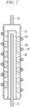
- FIG. 2 is a view showing a longitudinal cross-section of the cooling device according to an embodiment of the present invention.
- the cooling device for instantaneous cooling includes a housing 10 provided with an inlet 11 on one side and an outlet 12 on the other side, water to be cooled requiring cooling may flow into the inlet 11, and cooled cold water may be discharged through the outlet 12.
- the water to be cooled may be cooled by cold air formed by a refrigerant circulation pipe 20 provided to spirally wrap an outer surface of the housing 10.
- FIGS. 1 and 2 since the components shown in FIGS. 1 and 2 are not essential, it is possible, of course, to implement a cooling device having more or fewer components.
- the housing 10 forms the appearance of the cooling device, in which a water inflow pipe 110 having the inlet 11 is inserted into one side, and which may have the outlet 12 on the other side through which cold water cooling the water to be cooled flowing in through the inlet 11 is discharged.
- the outlet 12 may be provided on the other side of the housing 10 to form a flow path through which the cold water formed inside the housing 10 is discharged.
- the outlet 12 may be provided in the same direction as the inlet 11 depending on the number of pipes provided inside the housing 10, and in the present invention, the positions of the inlet 11 and the outlet 120 are not particularly limited.
- the water inflow pipe 110 is shaped like a tube with openings at both end portions, and may have the inlet 11 at one end portion through which the water to be cooled flows.
- the inlet 11 may be provided outside the housing 10, but the present invention does not specifically limit this.
- the other end portion of the water inflow pipe 110 inserted into one side of the housing 10 may be provided inside the housing 10.
- the other end portion of the water inflow pipe 110 that is, the end on the outlet 12 side, may be formed of a first opening, and thus the water to be cooled flowing in through the inlet 11 may flow along the water inflow pipe 110 and then be discharged through the first opening.
- the other end portion of the water inflow pipe 110 may be provided with a cooling pipe 120 with one end portion closed and spaced apart therefrom.
- the tubular cooling pipe 120 is provided inside the housing 10, and the water inflow pipe 110 may be provided to be inserted into the interior of the cooling pipe 120 along a longitudinal direction.
- the cooling pipe 120 with one end portion closed may be provided such that the closed one end portion covers the first opening of the water inflow pipe 110.
- the cooling pipe 120 with one end portion closed may have a separate cover member 50 combined to either one of both open end portions (see FIG. 7 ).
- the separate cover member 50 covers and combines to at least one end portion of a plurality of concentric pipes, thereby selectively closing or opening at least one end portion of the plurality of pipes.
- a plurality of grooves into which the plurality of pipes may be combined are formed on one surface of the circular or square cover member 50 corresponding to a cross-section of the pipe, and the cooling pipe 120 and a second inner pipe 125 may be completely fitted to a part of the plurality of grooves. Therefore, closed other end portions may be formed in the cooling pipe 120 and the second inner pipe 125.
- the water inflow pipe 110 or the first inner pipe 115 is inserted into another part of the plurality of grooves, and at least a part of the circumference of the groove into which the water inflow pipe 110 or the first inner pipe 115 is inserted is deeper than other parts. Therefore, a first opening or a second opening may be formed as flow paths through which a fluid may flow.
- the water to be cooled flowing in through the inlet 11 provided at one end portion of the water inflow pipe 110 may flow along the water inflow pipe 110 and be discharged through the first opening at the other end portion. Accordingly, a flow direction of the water to be cooled discharged from the first opening of the water inflow pipe 110 may be changed by the closed one end portion of the cooling pipe 120 covered by the water inflow pipe 110, and thereby the water to be cooled may flow along an inner wall of the cooling pipe 120.
- the water to be cooled flowing along the inner wall of the cooling pipe 120 may flow in a radial direction through the first passage formed through the end portion on the inlet 11 side in an outward direction, that is, toward the inner wall of the housing 10.
- the water to be cooled passing through the first passage flows in the opposite direction again along the inner wall of the housing 10, and may rotate along an ice spiral 30 as will be described later.
- the inner wall of the housing 10 may include the screw-shaped ice spiral 30 in a form of wrapping an inner peripheral surface of the housing 10.
- the refrigerant circulation pipe 20 formed along the ice spiral 30, that is, in a spiral form wrapping the housing 10, may be provided on the outer surface of the housing 10.
- the refrigerant circulation pipe 20 corresponds to the evaporator.
- the evaporator may evaporate a liquid refrigerant in low-temperature and low-pressure flowing in from the expansion valve to exchange heat with the surrounding.
- the compressor which sucks the gaseous refrigerant in low-temperature and low-pressure evaporated from the evaporator, pressurizes the refrigerant to a saturation pressure corresponding to the condensation temperature so that the pressurized refrigerant can be condensed and liquefied in the condenser.
- the condenser heat-exchanges between the gaseous refrigerant in high-temperature and high-pressure, which is pressurized in the compressor and discharged, and the surrounding air. Therefore, the gaseous refrigerant in high temperature can be condensed and liquefied by releasing heat.
- the expansion valve can exert a throttling action on the liquid refrigerant in high-temperature and high-pressure, which is condensed and liquefied by the condenser, to be converted into a liquid refrigerant in low-temperature and low-pressure.
- the water to be cooled flowing in through the inlet 11 is cooled on the inner peripheral surface of the housing 10 by the refrigerant circulation pipe 20 provided to spirally wrap the outer peripheral surface of the housing 10, and spiral ice, that is, the ice spiral 30 may be formed depending on the wrapped form of the refrigerant circulation pipe 20.
- the water to be cooled flowing in the radial direction through the first passage formed at one end portion of the cooling pipe 120 may come into contact with the screw-shaped ice spiral 30 and flow while rotating according to its shape.
- the water to be cooled flowing in the radial direction of the cooling pipe 120 through the first passage flows along the screw-shaped ice spiral 30, that is, along a flow path f3 shown in FIG. 3 , and the water to be cooled flowing along the ice spiral 30 may be guided to the outlet 12.
- the ice spiral 30 formed by the refrigerant circulation pipe 20 is spaced apart between adjacent ices formed along the longitudinal direction of the housing 10 in cross section, as shown in FIGS. 2 and 3 , so that it is preferable to form a flow path through which the water to be cooled can flow.
- the refrigerant circulation pipe 20 is disposed and formed on the outer peripheral surface of the housing 10 so that the ice spiral 30 is formed to be spaced apart between adjacent ices formed along the longitudinal direction of the housing 10 in the longitudinal cross-section.
- the water to be cooled flows toward the outlet 12 in a state of coming into contact with the surface of the screw-shaped ice spiral 30. Therefore, a contact time of the water to be cooled with ice increases and a contact area with ice expands. As a result, heat exchange efficiency is increased, and the cooling efficiency of the water to be cooled can be increased.
- the ice spiral 30 is formed to protrude in the inner direction of the housing 10, and a protruding inner end portion is formed up to the outer wall of the cooling pipe 120, or is formed up to at least a part of the inside of the cooling pipe 120, thereby being not formed inside the water inflow pipe 110.
- the present invention is not particularly limited, but the first passage (not shown) formed at one end portion of the cooling pipe 120, that is, at the end portion on the inlet 11 side, is formed through the pipe wall, and the first passage may form the flow path through which the water to be cooled can flow in the radial direction toward the inner wall of the housing 10 along the longitudinal direction of the cooling pipe 120.
- the first passage may be in a form of a plurality of fine holes perforated, and accordingly, it is preferable to allow the water to be cooled passing through the first passage to be finely sprayed.
- the water to be cooled flowing in through the inlet 11 may flow along the water inflow pipe 110 to form a flow path f1.
- the water to be cooled flowing in through the inlet 11 provided at one end portion of the water inflow pipe 110 may flow along the longitudinal direction of the water inflow pipe 110 and be discharged through the first opening at the other end portion.
- the water to be cooled discharged through the first opening may flow again in the opposite direction along the longitudinal direction of the cooling pipe 120 by the cooling pipe 120 covering the other end portion, thereby forming a flow path f2.
- the water to be cooled flowing on the inside along the water inflow pipe 110 and the cooling pipe 120 does not directly come into contact with the ice spiral 30, but may be roll-cooled by the cold air formed by the refrigerant circulation pipe 20 and the ice spiral 30.
- the water to be cooled flowing in the radial direction through the first passage formed at the end portion of the cooling pipe 120 on the inlet 11 side rotates toward the outlet 12 side along the screw-shaped ice spiral 30, thereby forming the flow path f3.
- the water to be cooled can be intensively cooled by directly contact with the ice spiral 30.
- the water to be cooled that flows into the housing 10 through the inlet 11 can be cooled in a short period of time by going through the roll-cooling and concentrated-cooling processes.
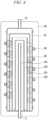
- FIG. 4 is a view showing a longitudinal cross-section of a cooling device according to another embodiment of the present invention
- FIG. 5 is a view showing a shape in which a fluid flows along a flow path in the cooling device of FIG. 4
- FIG. 6 is a view showing a cross-section of the cooling device of FIG. 4 .
- the cooling device may include a first inner pipe 115 and a second inner pipe 125 provided between the cooling pipe 120 and the housing 10.
- the first and second inner pipes 115 and 125 is configured such that the first inner pipe 115 may sequentially form an inner shell and the second inner pipe 125 may form an outer shell.
- a second opening may be formed at the other end of the first inner pipe 115, that is, the end portion on the outlet 12 side, and second passage formed through the pipe wall may be provided on one end of the second inner pipe 125, that is, the end portion on the inlet 11 side.
- the second passage like the first passage, may also be in a form of a plurality of fine holes perforated.
- the ice spiral 30 according to the present embodiment is formed to protrude in the inner direction on the inner wall of the housing 10, and the inner end portion of the protruding ice spiral 30 passes through the second inner pipe 125 to be formed up to the outer wall of the first inner pipe 115.
- the water to be cooled flowing in through the inlet 11 may flow along the water inflow pipe 110 to form the flow path f1.
- the water to be cooled flowing in through the inlet 11 provided at one end portion of the water inflow pipe 110 flows along the longitudinal direction of the water inflow pipe 110, and may be discharged through the first opening provided at the other end portion.
- the direction of the water to be cooled is changed in the opposite direction by the closed other end portion of the cooling pipe 120, which covers the other end portion of the water inflow pipe 110, and flows along the longitudinal direction of the cooling pipe 120 to form the flow path f2.
- the water to be cooled flowing in the radial direction through the first passage formed at the end portion of the cooling pipe 120 on the inlet 11 side may flow into the first inner pipe 115.
- the water to be cooled flowing in the first inner pipe 115 flows along the longitudinal direction of the first inner pipe 115 to form the flow path f3, and then may be discharged through the second opening provided at the other end of the first inner pipe 115.
- the water to be cooled flowing inside the water inflow pipe 110, the cooling pipe 120, and the first inner pipe 115 does not directly come into contact with the ice spiral 30, but may be roll-cooled by the cold air formed by the refrigerant circulation pipe 20 and the ice spiral 30.
- the water to be cooled discharged through the second opening provided at the other end of the first inner pipe 115 flows along the longitudinal direction of the inner wall of the second inner pipe 125 and can rotate along the ice spiral 30 formed in the inner wall of the second inner pipe 125 to form a flow path f41. Thereafter, the water to be cooled can flow into the inner wall of the housing 10 through the second passage formed through the pipe wall at one end of the second inner pipe 125.
- the water to be cooled flowing into the inner wall of the housing 10 through the second passage flows along the longitudinal direction of the inner wall of the housing 10, and rotates along the ice spiral 30 formed on the inner wall of the housing 10 to form a flow path f42, and then can be discharged into the outlet 12.
- the cooling efficiency can be further improved by the repeated concentrated-cooling process.
- first and second inner pipes 115 and 125, the cooling pipe 120, and the water inflow pipe 110 are provided in layers inside the housing 10, even if supercooling occurs with the refrigerant circulation pipe 20, the ice may not completely freeze up to the water inflow pipe 110.
- a thermal insulation material 40 may be provided on the outer surface of the housing 10 of the cooling device according to an embodiment of the present invention to wrap the housing 10.
- the present invention does not specifically limit a material of the thermal insulation material 40, as long as it can form heat insulation to prevent heat from being transferred between the inside and the outside.
- the outlet 12 can discharge cold water in which the water to be cooled is cooled, but it is necessary to adjust the temperature of the cold water discharged through the outlet 12.
- a valve (not shown) may be provided in the outlet 12 according to an embodiment of the present invention.
- the valve can mix the cold water discharged through the outlet 12 with a fluid with a temperature higher than that of the cold water, specifically the water to be cooled, and discharge mixed water whose temperature is adjusted by mixing.
- a flow rate of the fluid mixed with the cold water can be adjusted by an opening/closing rate of the valve to adjust the temperature of the mixed water discharged from the valve.
- the cold water with which the water to be cooled is cooled may be discharged through the outlet 12.
- the water to be cooled can flow into the outlet 12 and the cold water can be discharged through the inlet 11.
- the water to be cooled can flow in through the outlet 12 so that the water to be cooled first comes into contact with the surface of the ice spiral 30 and intensively cooled, and then the cold water can be discharged to the inlet 11 through the water inflow pipe 11.
- the cold water can be discharged to the inlet 11 through the water inflow pipe 11.
- the water to be cooled can flow into or the cooled cold water can be discharged from the inlet 11 of the housing 10, and simultaneously, the cooled cold water can be discharged from or the water to be cooled can flow into the outlet 12 of the housing 10.
- housing 10 of the cooling device according to the previous embodiments may be provided with the inlet 11 on one side and the outlet 12 on the other side, but the housing 10 of the cooling device according to another embodiment of the present invention may be provided with the inlet 11 and the outlet 12 on one side.
- FIG. 8 is a view showing an appearance of a cooling device according to another embodiment of the present invention
- FIG. 9 is a view showing a longitudinal cross-section of the cooling device according to another embodiment of the present invention.
- the water to be cooled flowing into the inlet 11 provided on one side of the housing 10 can be cooled by inducing back and forth at least once inside the housing 10, and discharged from the outlet 12 provided in the same direction as the direction in which the inlet 11 is provided.
- an odd number of third inner pipes 130 can be provided inside the housing 10 in addition to the water inflow pipe 110 and the cooling pipe 120.
- the water inflow pipe 110 having the inlet 11 into which the water to be cooled flows in, the third inner pipe 130 provided to be spaced apart from the outside of the water inflow pipe 110, and the cooling pipe 120 provided to be spaced apart from the outside of the third inner pipe 130 may be provided inside the housing 10.
- the water to be cooled flowing along the water inflow pipe 110, the third inner pipe 130, and the cooling pipe 120 can be roll-cooled, and be rotated along the ice spiral 30 formed in a screw shape on the inner wall of the housing 10 to be intensively cooled, and then be discharged through the outlet 12 provided outside the cooling pipe 120.
- the water to be cooled can be rotated along the ice spiral 30 formed in the screw shape on the inner wall of the housing 10, be roll-cooled, and then flow along the cooling pipe 120, the third inner pipe 130, and the water inflow pipe 110 to be intensively cooled, and then be discharged through the inlet 11 of the water inflow pipe 110.
- the water inflow pipe 110, the third inner pipe 130, and the cooling pipe 120 are provided inside the housing 10.
- at least one of cover members 50a and 50b may be provided to selectively block one end or the other end of at least one of the water inflow pipe 110, the third inner pipe 130, and the cooling pipe 120.
- At least one air hole may be provided in the cover member 50a provided around the inlet 11 or the outlet 12 of the water inflow pipe 110.
- the air inside the housing 10 when the air inside the housing 10 exhausts to the outside through the air hole, it can exhausts through the inlet 11 or the outlet 12 located around it.
- a plurality of air holes may be provided in the cover member 50a, and the plurality of air holes can be connected with an airline in the form of a groove or conduit as a passage through which air can flow therebetween them, as shown in FIG. 11 .
- the housing 10 may be provided with at least one of drain pipes 13a and 13b for discharging the water stored inside to the outside, as shown in FIGS. 8 and 9 .
- At least one of drain pipes 13a and 13b is provided to enable communication between the inside and the outside at any position of the housing 10, so that the water stored inside the housing 10 can be discharged to the outside when the valve is opened.
Landscapes
- Engineering & Computer Science (AREA)
- Physics & Mathematics (AREA)
- Thermal Sciences (AREA)
- Mechanical Engineering (AREA)
- General Engineering & Computer Science (AREA)
- Chemical & Material Sciences (AREA)
- Combustion & Propulsion (AREA)
- Heat-Exchange Devices With Radiators And Conduit Assemblies (AREA)
- Devices That Are Associated With Refrigeration Equipment (AREA)
- Devices For Dispensing Beverages (AREA)
Abstract
Description
- The present invention relates to a cooling device that can produce cold water through instantaneously cooling water to be cooled that requires cooling, such as in a water purifier, a hot/cold water dispenser, or a refrigerator.
- In a water purifier, a hot/cold water dispenser, or the like, a cold water tank is used to cool room temperature water, which is raw water. The water stored in the cold water tank is cooled and stored, and then the cold water stored in the cold water tank can be discharged to the outside by a cold water discharge operation.
- In a case where the cold water tank is used to cool the water to be cooled stored inside, there are disadvantages that there is a risk that the water stored inside the cold water tank is contaminated, electrical energy is required for cooling even when the cold water is not discharged, it takes time to make cold water again in a case where water stored in the cold water tank is used up, and the like.
- Accordingly, there is an increasing demand for a technology that can instantaneously cool and discharge room temperature water that is water to be cooled, and to this end, the present inventors have proposed a device capable of instantaneous cooling in
Korean Patent Registration No. 10-1804385 - However, the present inventors would like to propose another method of making cold water by instantaneously cooling the water to be cooled.
- The present invention seeks to provide a cooling device for instantaneous cooling to make cold water by cooling water to be cooled flowed in from the outside within a short period of time.
- In order to solve the above problem, the present invention provides a cooling device for instantaneous cooling, the cooling device including a water inflow pipe having an inlet into which water to be cooled requiring cooling flows; a housing having an outlet through which cold water cooling the water to be cooled flowing in through the inlet is discharged; a refrigerant circulation pipe provided to spirally wrap an outer surface of the housing; and a screw-shaped ice spiral formed by the refrigerant circulation pipe on an inner wall of the housing.
- According to an embodiment, the cooling device for instantaneous cooling may further include a cooling pipe provided inside the housing, and provided into which the water inflow pipe is inserted along a longitudinal direction, in which the ice spiral may not be formed inside the water inflow pipe or the cooling pipe.
- According to an embodiment, the cooling device for instantaneous cooling may further include a first passage formed through toward the inner wall of the housing at one end portion of the cooling pipe, in which the first passage may have a plurality of fine holes perforated.
- According to an embodiment, the cooling device for instantaneous cooling may further include first and second inner pipes provided between the cooling pipe and the housing, in which the water to be cooled may flow in through the inlet provided at one end of the water inflow pipe, and be discharged through a first opening provided at the other end of the water inflow pipe, a direction of the water to be cooled discharged to the first opening be changed by the closed other end portion of the cooling pipe, the water to be cooled flow along a longitudinal direction of the cooling pipe, and then flow into the first inner pipe, the water to be cooled flowing into the first inner pipe may flow along the longitudinal direction of the first inner pipe, and then be discharged through a second opening provided at the other end of the first inner pipe, the water to be cooled discharged through the second opening may flow along the longitudinal direction of an inner wall of the second inner pipe, rotate along the ice spiral, and then flow into the inner wall of the housing through a second passage formed through one end of the second inner pipe, and the water to be cooled flowing into the inner wall of the housing may flow along the longitudinal direction of the inner wall of the housing, rotate along the ice spiral, and then be discharged into the outlet.
- According to an embodiment, the second passage may have a plurality of fine holes perforated.
- According to an embodiment, the closed other end portion of the cooling pipe may be formed by combining a separate cover member with a tubular pipe that is open at both ends.
- According to an embodiment, the cover member may be configured such that the cooling pipe and the second inner pipe are fitted into a plurality of grooves that are concentrically provided to be combined to form the closed other end portion in the cooling pipe and the second inner pipe.
- According to an embodiment, the cover member may be configured such that a part of the plurality of grooves has a deep depth on at least a part of a circumference to form a flow path through which a fluid flows in a radial direction.
- According to an embodiment, the cooling device for instantaneous cooling may further include a thermal insulation material provided on the outer surface of the housing to wrap the housing.
- According to an embodiment, the cooling device for instantaneous cooling may further include a valve provided in the outlet, in which the valve may mix cold water discharged through the outlet with a fluid having a higher temperature than that of the cold water, and discharge mixed water of which a temperature is adjusted by mixing.
- According to an embodiment, the water to be cooled may flow into the outlet, and cold water be discharged through the inlet.
- According to an embodiment, the water to be cooled flowing in through the outlet may rotate along the ice spiral and be roll-cooled.
- According to an embodiment, the inlet and the outlet may be provided on one side of the housing in the same direction.
- According to an embodiment, the housing may include the water inflow pipe having the inlet through which the water to be cooled flows in, a third inner pipe provided to be spaced apart from an outside of the water inflow pipe, and a cooling pipe provided to be spaced apart from an outside of the third inner pipe, and the outlet through which cold water is discharged may be provided on an outside of the cooling pipe.
- According to an embodiment, the water to be cooled may flow into the outlet, and cold water be discharged through the inlet.
- According to an embodiment, at least one cover member, which selectively blocks one end or the other end of at least one of the water inflow pipe having a tubular shape with both ends open, the third inner pipe, and the cooling pipe, may be provided on at least one side of the housing.
- According to an embodiment, the cover member provided around the inlet or the outlet may include at least one air hole to allow inside air to be exhausted to the outside.
- The cooling device according to an embodiment of the present invention can make cold water by cooling the water to be cooled flowed in from the outside in a short period of time by flowing along the spiral ice.
- Due to the pipes provided in multiple layers inside, even if supercooling occurs through the refrigerant circulation pipe, it is possible to prevent complete freezing up to the water inflow pipe through which the water to be cooled flows in from the outside.
-
-
FIG. 1 is a view showing an appearance of a cooling device according to an embodiment of the present invention. -
FIG. 2 is a view showing a longitudinal cross-section of the cooling device according to an embodiment of the present invention. -
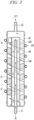
FIG. 3 is a view showing a shape in which a fluid flows along a flow path in the cooling device ofFIG. 2 . -
FIG. 4 is a view showing a longitudinal cross-section of a cooling device according to another embodiment of the present invention. -
FIG. 5 is a view showing a shape in which a fluid flows along a flow path in the cooling device ofFIG. 4 . -
FIG. 6 is a view showing a cross-section of the cooling device ofFIG. 4 . -
FIG. 7 is a view showing a shape in which a cover member according to an embodiment of the present invention is combined. -
FIG. 8 is a view showing an appearance of a cooling device according to another embodiment of the present invention. -
FIG. 9 is a view showing a longitudinal cross-section of the cooling device according to another embodiment of the present invention. -
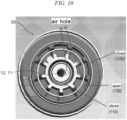
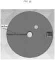
FIGS. 10 and11 are views showing an air hole of a cooling device according to another embodiment of the present invention. -
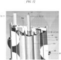
FIG. 12 is a view showing a flow path through which internal air of a cooling device according to another embodiment of the present invention is exhausted to the outside along an air hole. - Hereinafter, embodiments disclosed in the present specification will be described in detail with reference to the attached drawings. However, identical or similar components will be assigned the same reference numbers regardless of drawing numerals, and duplicate descriptions thereof will be omitted. The suffixes "module" and "portion" for the components used in the following description are given or used interchangeably only for the ease of preparing the specification, and do not have distinct meanings or roles in themselves. In addition, in describing the embodiments disclosed in this specification, if it is determined that detailed descriptions of related known technologies may obscure the gist of the embodiments disclosed in this specification, the detailed descriptions will be omitted. In addition, it should be understood that the attached drawings are only for easy understanding of the embodiments disclosed in this specification, and the technical idea disclosed in this specification is not limited by the attached drawings, and includes all changes, equivalents or substitutes included in the gist and technical scope of the present invention are not limited.
- When a component is said to be "connected" or "coupled" to another component, it should be understood that it may be directly connected to or coupled to another component, but other components may exist therebetween. On the other hand, when it is mentioned that a component is "directly connected" or "directly coupled" to another component, it should be understood that there are no other components therebetween.
- Singular expressions include plural expressions unless the context clearly dictates otherwise.
- In this specification, it should be understood that terms such as "include" or "have" are intended to indicate the presence of features, numbers, steps, operations, components, parts, or combinations thereof described in the specification, and the presence or the addition possibility of one or more other features, elements, numbers, steps, operations, components, parts, or combinations thereof are not excluded in advance.
-
FIG. 1 is a view showing an appearance of a cooling device according to an embodiment of the present invention, andFIG. 2 is a view showing a longitudinal cross-section of the cooling device according to an embodiment of the present invention. - As shown in
FIGS. 1 and2 , the cooling device for instantaneous cooling according to an embodiment of the present invention includes ahousing 10 provided with aninlet 11 on one side and anoutlet 12 on the other side, water to be cooled requiring cooling may flow into theinlet 11, and cooled cold water may be discharged through theoutlet 12. In this case, the water to be cooled may be cooled by cold air formed by arefrigerant circulation pipe 20 provided to spirally wrap an outer surface of thehousing 10. - However, since the components shown in
FIGS. 1 and2 are not essential, it is possible, of course, to implement a cooling device having more or fewer components. - Below, each component will be considered.
- The
housing 10 forms the appearance of the cooling device, in which awater inflow pipe 110 having theinlet 11 is inserted into one side, and which may have theoutlet 12 on the other side through which cold water cooling the water to be cooled flowing in through theinlet 11 is discharged. - In this case, the
outlet 12 may be provided on the other side of thehousing 10 to form a flow path through which the cold water formed inside thehousing 10 is discharged. However, theoutlet 12 may be provided in the same direction as theinlet 11 depending on the number of pipes provided inside thehousing 10, and in the present invention, the positions of theinlet 11 and theoutlet 120 are not particularly limited. - The
water inflow pipe 110 is shaped like a tube with openings at both end portions, and may have theinlet 11 at one end portion through which the water to be cooled flows. In this case, theinlet 11 may be provided outside thehousing 10, but the present invention does not specifically limit this. - The other end portion of the
water inflow pipe 110 inserted into one side of thehousing 10 may be provided inside thehousing 10. In this case, the other end portion of thewater inflow pipe 110, that is, the end on theoutlet 12 side, may be formed of a first opening, and thus the water to be cooled flowing in through theinlet 11 may flow along thewater inflow pipe 110 and then be discharged through the first opening. - In addition, the other end portion of the
water inflow pipe 110 may be provided with acooling pipe 120 with one end portion closed and spaced apart therefrom. - The
tubular cooling pipe 120 is provided inside thehousing 10, and thewater inflow pipe 110 may be provided to be inserted into the interior of thecooling pipe 120 along a longitudinal direction. In this case, thecooling pipe 120 with one end portion closed may be provided such that the closed one end portion covers the first opening of thewater inflow pipe 110. - According to an embodiment of the present invention, the
cooling pipe 120 with one end portion closed may have aseparate cover member 50 combined to either one of both open end portions (seeFIG. 7 ). - However, the
separate cover member 50 according to an embodiment of the present invention covers and combines to at least one end portion of a plurality of concentric pipes, thereby selectively closing or opening at least one end portion of the plurality of pipes. - Specifically, a plurality of grooves into which the plurality of pipes may be combined are formed on one surface of the circular or
square cover member 50 corresponding to a cross-section of the pipe, and thecooling pipe 120 and a secondinner pipe 125 may be completely fitted to a part of the plurality of grooves. Therefore, closed other end portions may be formed in thecooling pipe 120 and the secondinner pipe 125. - In this case, the
water inflow pipe 110 or the firstinner pipe 115 is inserted into another part of the plurality of grooves, and at least a part of the circumference of the groove into which thewater inflow pipe 110 or the firstinner pipe 115 is inserted is deeper than other parts. Therefore, a first opening or a second opening may be formed as flow paths through which a fluid may flow. - Accordingly, as shown in
FIG. 3 , the water to be cooled flowing in through theinlet 11 provided at one end portion of thewater inflow pipe 110 may flow along thewater inflow pipe 110 and be discharged through the first opening at the other end portion. Accordingly, a flow direction of the water to be cooled discharged from the first opening of thewater inflow pipe 110 may be changed by the closed one end portion of thecooling pipe 120 covered by thewater inflow pipe 110, and thereby the water to be cooled may flow along an inner wall of thecooling pipe 120. - The water to be cooled flowing along the inner wall of the
cooling pipe 120 may flow in a radial direction through the first passage formed through the end portion on theinlet 11 side in an outward direction, that is, toward the inner wall of thehousing 10. The water to be cooled passing through the first passage flows in the opposite direction again along the inner wall of thehousing 10, and may rotate along anice spiral 30 as will be described later. - That is, the inner wall of the
housing 10 may include the screw-shapedice spiral 30 in a form of wrapping an inner peripheral surface of thehousing 10. - For this end, the
refrigerant circulation pipe 20 formed along theice spiral 30, that is, in a spiral form wrapping thehousing 10, may be provided on the outer surface of thehousing 10. - As the refrigerant flows inside the
refrigerant circulation pipe 20, a surrounding area thereof can be cooled. As an example, among a compressor, a condenser, an evaporator, and an expansion valve that constitute a refrigeration cycle, therefrigerant circulation pipe 20 corresponds to the evaporator. The evaporator may evaporate a liquid refrigerant in low-temperature and low-pressure flowing in from the expansion valve to exchange heat with the surrounding. In other words, the compressor, which sucks the gaseous refrigerant in low-temperature and low-pressure evaporated from the evaporator, pressurizes the refrigerant to a saturation pressure corresponding to the condensation temperature so that the pressurized refrigerant can be condensed and liquefied in the condenser. The condenser heat-exchanges between the gaseous refrigerant in high-temperature and high-pressure, which is pressurized in the compressor and discharged, and the surrounding air. Therefore, the gaseous refrigerant in high temperature can be condensed and liquefied by releasing heat. The expansion valve can exert a throttling action on the liquid refrigerant in high-temperature and high-pressure, which is condensed and liquefied by the condenser, to be converted into a liquid refrigerant in low-temperature and low-pressure. - As a result, the water to be cooled flowing in through the
inlet 11 is cooled on the inner peripheral surface of thehousing 10 by therefrigerant circulation pipe 20 provided to spirally wrap the outer peripheral surface of thehousing 10, and spiral ice, that is, theice spiral 30 may be formed depending on the wrapped form of therefrigerant circulation pipe 20. - Accordingly, the water to be cooled flowing in the radial direction through the first passage formed at one end portion of the
cooling pipe 120 may come into contact with the screw-shapedice spiral 30 and flow while rotating according to its shape. - That is, the water to be cooled flowing in the radial direction of the
cooling pipe 120 through the first passage flows along the screw-shapedice spiral 30, that is, along a flow path f3 shown inFIG. 3 , and the water to be cooled flowing along theice spiral 30 may be guided to theoutlet 12. - Here, the
ice spiral 30 formed by therefrigerant circulation pipe 20 is spaced apart between adjacent ices formed along the longitudinal direction of thehousing 10 in cross section, as shown inFIGS. 2 and3 , so that it is preferable to form a flow path through which the water to be cooled can flow. - In other words, it is preferable that the
refrigerant circulation pipe 20 is disposed and formed on the outer peripheral surface of thehousing 10 so that theice spiral 30 is formed to be spaced apart between adjacent ices formed along the longitudinal direction of thehousing 10 in the longitudinal cross-section. - Accordingly, the water to be cooled flows toward the
outlet 12 in a state of coming into contact with the surface of the screw-shapedice spiral 30. Therefore, a contact time of the water to be cooled with ice increases and a contact area with ice expands. As a result, heat exchange efficiency is increased, and the cooling efficiency of the water to be cooled can be increased. - In addition, as shown in
FIGS. 2 and3 , it is preferable that theice spiral 30 is formed to protrude in the inner direction of thehousing 10, and a protruding inner end portion is formed up to the outer wall of thecooling pipe 120, or is formed up to at least a part of the inside of thecooling pipe 120, thereby being not formed inside thewater inflow pipe 110. - Meanwhile, the present invention is not particularly limited, but the first passage (not shown) formed at one end portion of the
cooling pipe 120, that is, at the end portion on theinlet 11 side, is formed through the pipe wall, and the first passage may form the flow path through which the water to be cooled can flow in the radial direction toward the inner wall of thehousing 10 along the longitudinal direction of thecooling pipe 120. - In this case, the first passage may be in a form of a plurality of fine holes perforated, and accordingly, it is preferable to allow the water to be cooled passing through the first passage to be finely sprayed.
- The area of the water to be cooled coming in contact with the surface of the
ice spiral 30, which passes through the first passage and is finely sprayed, increases, thereby improving the cooling efficiency of the water to be cooled. - When the water to be cooled flowing in through the
inlet 11 from the cooling device according to an embodiment of the present invention is discharged through theoutlet 12, the flow path of the water to be cooled formed in the process is as shown inFIG. 3 . - As shown in
FIG. 3 , in the cooling device according to an embodiment of the present invention, the water to be cooled flowing in through theinlet 11 may flow along thewater inflow pipe 110 to form a flow path f1. - The water to be cooled flowing in through the
inlet 11 provided at one end portion of thewater inflow pipe 110 may flow along the longitudinal direction of thewater inflow pipe 110 and be discharged through the first opening at the other end portion. The water to be cooled discharged through the first opening may flow again in the opposite direction along the longitudinal direction of thecooling pipe 120 by the coolingpipe 120 covering the other end portion, thereby forming a flow path f2. - The water to be cooled flowing on the inside along the
water inflow pipe 110 and thecooling pipe 120 does not directly come into contact with theice spiral 30, but may be roll-cooled by the cold air formed by therefrigerant circulation pipe 20 and theice spiral 30. - Thereafter, the water to be cooled flowing in the radial direction through the first passage formed at the end portion of the
cooling pipe 120 on theinlet 11 side rotates toward theoutlet 12 side along the screw-shapedice spiral 30, thereby forming the flow path f3. In this case, the water to be cooled can be intensively cooled by directly contact with theice spiral 30. - The water to be cooled that flows into the
housing 10 through theinlet 11 can be cooled in a short period of time by going through the roll-cooling and concentrated-cooling processes. - Meanwhile,
FIG. 4 is a view showing a longitudinal cross-section of a cooling device according to another embodiment of the present invention,FIG. 5 is a view showing a shape in which a fluid flows along a flow path in the cooling device ofFIG. 4 , andFIG. 6 is a view showing a cross-section of the cooling device ofFIG. 4 . - As shown in
FIGS. 4 and6 , the cooling device according to another embodiment of the present invention may include a firstinner pipe 115 and a secondinner pipe 125 provided between the coolingpipe 120 and thehousing 10. In this case, the first and secondinner pipes inner pipe 115 may sequentially form an inner shell and the secondinner pipe 125 may form an outer shell. - In this case, a second opening may be formed at the other end of the first
inner pipe 115, that is, the end portion on theoutlet 12 side, and second passage formed through the pipe wall may be provided on one end of the secondinner pipe 125, that is, the end portion on theinlet 11 side. Here, the second passage, like the first passage, may also be in a form of a plurality of fine holes perforated. - In addition, it is preferable that the
ice spiral 30 according to the present embodiment is formed to protrude in the inner direction on the inner wall of thehousing 10, and the inner end portion of the protrudingice spiral 30 passes through the secondinner pipe 125 to be formed up to the outer wall of the firstinner pipe 115. - Accordingly, when the water to be cooled flowing in through the
inlet 11 in the cooling device according to the present embodiment is discharged through theoutlet 12, the flow path of the water to be cooled formed in the process is as shown inFIG. 5 . - As shown in
FIG. 5 , in the cooling device according to the present embodiment, the water to be cooled flowing in through theinlet 11 may flow along thewater inflow pipe 110 to form the flow path f1. - The water to be cooled flowing in through the
inlet 11 provided at one end portion of thewater inflow pipe 110 flows along the longitudinal direction of thewater inflow pipe 110, and may be discharged through the first opening provided at the other end portion. In this case, the direction of the water to be cooled is changed in the opposite direction by the closed other end portion of thecooling pipe 120, which covers the other end portion of thewater inflow pipe 110, and flows along the longitudinal direction of thecooling pipe 120 to form the flow path f2. - Thereafter, the water to be cooled flowing in the radial direction through the first passage formed at the end portion of the
cooling pipe 120 on theinlet 11 side may flow into the firstinner pipe 115. The water to be cooled flowing in the firstinner pipe 115 flows along the longitudinal direction of the firstinner pipe 115 to form the flow path f3, and then may be discharged through the second opening provided at the other end of the firstinner pipe 115. - Here, the water to be cooled flowing inside the
water inflow pipe 110, thecooling pipe 120, and the firstinner pipe 115 does not directly come into contact with theice spiral 30, but may be roll-cooled by the cold air formed by therefrigerant circulation pipe 20 and theice spiral 30. - The water to be cooled discharged through the second opening provided at the other end of the first
inner pipe 115 flows along the longitudinal direction of the inner wall of the secondinner pipe 125 and can rotate along theice spiral 30 formed in the inner wall of the secondinner pipe 125 to form a flow path f41. Thereafter, the water to be cooled can flow into the inner wall of thehousing 10 through the second passage formed through the pipe wall at one end of the secondinner pipe 125. - The water to be cooled flowing into the inner wall of the
housing 10 through the second passage flows along the longitudinal direction of the inner wall of thehousing 10, and rotates along theice spiral 30 formed on the inner wall of thehousing 10 to form a flow path f42, and then can be discharged into theoutlet 12. - In this way, in the cooling device according to the present embodiment, after roll-cooling, since the water to be cooled can flow back and forth along the flow paths f41 and f42 in direct contact with the
ice spiral 30, the cooling efficiency can be further improved by the repeated concentrated-cooling process. - In addition, since the first and second
inner pipes cooling pipe 120, and thewater inflow pipe 110 are provided in layers inside thehousing 10, even if supercooling occurs with therefrigerant circulation pipe 20, the ice may not completely freeze up to thewater inflow pipe 110. - Meanwhile, as shown in
FIGS. 4 to 6 , athermal insulation material 40 may be provided on the outer surface of thehousing 10 of the cooling device according to an embodiment of the present invention to wrap thehousing 10. - The present invention does not specifically limit a material of the
thermal insulation material 40, as long as it can form heat insulation to prevent heat from being transferred between the inside and the outside. - Meanwhile, the
outlet 12 according to an embodiment of the present invention can discharge cold water in which the water to be cooled is cooled, but it is necessary to adjust the temperature of the cold water discharged through theoutlet 12. - Accordingly, a valve (not shown) may be provided in the
outlet 12 according to an embodiment of the present invention. In this case, the valve can mix the cold water discharged through theoutlet 12 with a fluid with a temperature higher than that of the cold water, specifically the water to be cooled, and discharge mixed water whose temperature is adjusted by mixing. - In this case, a flow rate of the fluid mixed with the cold water can be adjusted by an opening/closing rate of the valve to adjust the temperature of the mixed water discharged from the valve.
- Meanwhile, when the water to be cooled flows into the
inlet 11 of thehousing 10 according to the previous embodiment, the cold water with which the water to be cooled is cooled may be discharged through theoutlet 12. However, according to another embodiment of the present invention, conversely, the water to be cooled can flow into theoutlet 12 and the cold water can be discharged through theinlet 11. - That is, in the reverse order, rather than in the order of roll-cooling and then intensively cooling, the water to be cooled can flow in through the
outlet 12 so that the water to be cooled first comes into contact with the surface of theice spiral 30 and intensively cooled, and then the cold water can be discharged to theinlet 11 through thewater inflow pipe 11. In this case, there is an effect of reducing the temperature deviation of the cold water being discharged. - Accordingly, the water to be cooled can flow into or the cooled cold water can be discharged from the
inlet 11 of thehousing 10, and simultaneously, the cooled cold water can be discharged from or the water to be cooled can flow into theoutlet 12 of thehousing 10. - In addition, the
housing 10 of the cooling device according to the previous embodiments may be provided with theinlet 11 on one side and theoutlet 12 on the other side, but thehousing 10 of the cooling device according to another embodiment of the present invention may be provided with theinlet 11 and theoutlet 12 on one side. -
FIG. 8 is a view showing an appearance of a cooling device according to another embodiment of the present invention, andFIG. 9 is a view showing a longitudinal cross-section of the cooling device according to another embodiment of the present invention. - As shown in
FIGS. 8 and9 , the water to be cooled flowing into theinlet 11 provided on one side of thehousing 10 can be cooled by inducing back and forth at least once inside thehousing 10, and discharged from theoutlet 12 provided in the same direction as the direction in which theinlet 11 is provided. - In a case where both the
inlet 11 and theoutlet 12 are provided on one side of thehousing 10, an odd number of thirdinner pipes 130 can be provided inside thehousing 10 in addition to thewater inflow pipe 110 and thecooling pipe 120. - As a basic example, as shown in
FIG. 9 , thewater inflow pipe 110 having theinlet 11 into which the water to be cooled flows in, the thirdinner pipe 130 provided to be spaced apart from the outside of thewater inflow pipe 110, and thecooling pipe 120 provided to be spaced apart from the outside of the thirdinner pipe 130 may be provided inside thehousing 10. - Accordingly, the water to be cooled flowing along the
water inflow pipe 110, the thirdinner pipe 130, and thecooling pipe 120 can be roll-cooled, and be rotated along theice spiral 30 formed in a screw shape on the inner wall of thehousing 10 to be intensively cooled, and then be discharged through theoutlet 12 provided outside thecooling pipe 120. - As described above, in a case where the water to be cooled flows into the
outlet 12, in the reverse order, the water to be cooled can be rotated along theice spiral 30 formed in the screw shape on the inner wall of thehousing 10, be roll-cooled, and then flow along thecooling pipe 120, the thirdinner pipe 130, and thewater inflow pipe 110 to be intensively cooled, and then be discharged through theinlet 11 of thewater inflow pipe 110. - In this way, the
water inflow pipe 110, the thirdinner pipe 130, and thecooling pipe 120 are provided inside thehousing 10. In this case, in order to form a flow of the water to be cooled as shown inFIG. 9 , at least one ofcover members water inflow pipe 110, the thirdinner pipe 130, and thecooling pipe 120. - In addition, according to an embodiment of the present invention, the
housing 10 may include at least one air hole to exhaust the air filled inside to the outside, and according to a preferred embodiment, at least one air hole may be formed in thecover members - As an example, in a case where the cooling water flows into the
housing 10 and is pressurized, the air inside thehousing 10 may be exhausted to the outside through the air hole. - In this case, for the air hole, according to a specific embodiment, as shown in
FIGS. 10 to 12 , at least one air hole may be provided in thecover member 50a provided around theinlet 11 or theoutlet 12 of thewater inflow pipe 110. - Accordingly, when the air inside the
housing 10 exhausts to the outside through the air hole, it can exhausts through theinlet 11 or theoutlet 12 located around it. - In this case, according to a more preferred embodiment, a plurality of air holes may be provided in the
cover member 50a, and the plurality of air holes can be connected with an airline in the form of a groove or conduit as a passage through which air can flow therebetween them, as shown inFIG. 11 . - That is, the air inside the
housing 10 can be exhausted to the outside along the air hole and airline, and through theinlet 11 or theoutlet 12. - Meanwhile, the
housing 10 according to an embodiment of the present invention may be provided with at least one ofdrain pipes FIGS. 8 and9 . - At least one of
drain pipes housing 10, so that the water stored inside thehousing 10 can be discharged to the outside when the valve is opened. - Above, preferred embodiments of the present invention have been described in detail with reference to the drawings. The description of the present invention is for illustrative purposes, and those skilled in the art will understand that the present invention can be easily modified into other specific forms without changing its technical idea or essential features.
- Accordingly, the scope of the present invention is indicated by the claims described later rather than the detailed description above, and it must be interpreted that all changes or modified forms derived from the meaning and scope of the claims and their equivalent concepts are included in the scope of the present invention.
Claims (18)
- A cooling device for instantaneous cooling, the cooling device comprising:a water inflow pipe having an inlet into which water to be cooled requiring cooling flows;a housing having an outlet through which cold water cooling the water to be cooled flowing in through the inlet is discharged;a refrigerant circulation pipe provided to spirally wrap an outer surface of the housing; anda screw-shaped ice spiral formed by the refrigerant circulation pipe on an inner wall of the housing.
- The cooling device for instantaneous cooling according to Claim 1, further comprising:a cooling pipe provided inside the housing, and provided into which the water inflow pipe is inserted along a longitudinal direction,wherein the ice spiral is not formed inside the water inflow pipe or the cooling pipe.
- The cooling device for instantaneous cooling according to Claim 1, further comprising:a first passage formed through toward the inner wall of the housing at one end portion of the cooling pipe,wherein the first passage has a plurality of fine holes perforated.
- The cooling device for instantaneous cooling according to Claim 1, wherein the water to be cooled flowing inside the water inflow pipe and the cooling pipe is roll-cooled, and the water to be cooled rotating along the ice spiral is intensively cooled on an outside of the cooling pipe.
- The cooling device for instantaneous cooling according to Claim 1, further comprising:first and second inner pipes provided between the cooling pipe and the housing,wherein the water to be cooled flows in through the inlet provided at one end of the water inflow pipe, and is discharged through a first opening provided at the other end of the water inflow pipe, a direction of the water to be cooled discharged to the first opening is changed by the closed other end portion of the cooling pipe, the water to be cooled flows along a longitudinal direction of the cooling pipe, and then flows into the first inner pipe,the water to be cooled flowing into the first inner pipe flows along the longitudinal direction of the first inner pipe, and then is discharged through a second opening provided at the other end of the first inner pipe,the water to be cooled discharged through the second opening flows along the longitudinal direction of an inner wall of the second inner pipe, rotates along the ice spiral, and then flows into the inner wall of the housing through a second passage formed through one end of the second inner pipe, andthe water to be cooled flowing into the inner wall of the housing flows along the longitudinal direction of the inner wall of the housing, rotates along the ice spiral, and then is discharged into the outlet.
- The cooling device for instantaneous cooling according to Claim 5, wherein the second passage has a plurality of fine holes perforated.
- The cooling device for instantaneous cooling according to Claim 5, wherein the closed other end portion of the cooling pipe is formed by combining a separate cover member with a tubular pipe that is open at both ends.
- The cooling device for instantaneous cooling according to Claim 7, wherein the cover member is configured such that the cooling pipe and the second inner pipe are fitted into a plurality of grooves that are concentrically provided to be combined to form the closed other end portion in the cooling pipe and the second inner pipe.
- The cooling device for instantaneous cooling according to Claim 8, wherein the cover member is configured such that a part of the plurality of grooves has a deep depth on at least a part of a circumference to form a flow path through which a fluid flows in a radial direction.
- The cooling device for instantaneous cooling according to Claim 1, further comprising:
a thermal insulation material provided on the outer surface of the housing to wrap the housing. - The cooling device for instantaneous cooling according to Claim 1, further comprising:a valve provided in the outlet,wherein the valve mixes cold water discharged through the outlet with a fluid having a higher temperature than that of the cold water, and discharges mixed water of which a temperature is adjusted by mixing.
- The cooling device for instantaneous cooling according to any one of Claims 1 to 3, wherein the water to be cooled flows into the outlet, and cold water is discharged through the inlet.
- The cooling device for instantaneous cooling according to Claim 12, wherein the water to be cooled flowing in through the outlet rotates along the ice spiral and is roll-cooled.
- The cooling device for instantaneous cooling according to Claim 1, wherein the inlet and the outlet are provided on one side of the housing in the same direction.
- The cooling device for instantaneous cooling according to Claim 14, wherein the housing includes the water inflow pipe having the inlet through which the water to be cooled flows in, a third inner pipe provided to be spaced apart from an outside of the water inflow pipe, and a cooling pipe provided to be spaced apart from an outside of the third inner pipe, and the outlet through which cold water is discharged is provided on an outside of the cooling pipe.
- The cooling device for instantaneous cooling according to Claim 15, wherein the water to be cooled flows into the outlet, and the cold water is discharged through the inlet.
- The cooling device for instantaneous cooling according to Claim 15, wherein at least one cover member, which selectively blocks one end or the other end of at least one of the water inflow pipe having a tubular shape with both ends open, the third inner pipe, and the cooling pipe, is provided on at least one side of the housing.
- The cooling device for instantaneous cooling according to Claim 17, wherein the cover member provided around the inlet or the outlet includes at least one air hole to allow inside air to be exhausted to the outside.
Applications Claiming Priority (2)
| Application Number | Priority Date | Filing Date | Title |
|---|---|---|---|
| KR20210164330 | 2021-11-25 | ||
| PCT/KR2022/018897 WO2023096424A1 (en) | 2021-11-25 | 2022-11-25 | Cooling device for instantaneous cooling |
Publications (2)
| Publication Number | Publication Date |
|---|---|
| EP4382838A1 true EP4382838A1 (en) | 2024-06-12 |
| EP4382838A4 EP4382838A4 (en) | 2025-07-16 |
Family
ID=86540174
Family Applications (1)
| Application Number | Title | Priority Date | Filing Date |
|---|---|---|---|
| EP22899106.3A Pending EP4382838A4 (en) | 2021-11-25 | 2022-11-25 | Cooling device for instant cooling |
Country Status (6)
| Country | Link |
|---|---|
| US (1) | US20240210103A1 (en) |
| EP (1) | EP4382838A4 (en) |
| JP (1) | JP2024535051A (en) |
| KR (1) | KR102644679B1 (en) |
| CN (1) | CN118119812A (en) |
| WO (1) | WO2023096424A1 (en) |
Families Citing this family (1)
| Publication number | Priority date | Publication date | Assignee | Title |
|---|---|---|---|---|
| KR20250134943A (en) | 2024-03-05 | 2025-09-12 | 박사언 | Cooling system for instant cooling |
Family Cites Families (12)
| Publication number | Priority date | Publication date | Assignee | Title |
|---|---|---|---|---|
| US2496466A (en) * | 1947-10-09 | 1950-02-07 | Temprite Products Corp | Liquid cooling apparatus |
| JP2563617Y2 (en) * | 1991-04-25 | 1998-02-25 | 東芝機械株式会社 | Water cooler |
| JPH05296633A (en) * | 1992-04-20 | 1993-11-09 | Sawafuji Electric Co Ltd | Hot / cold water machine |
| KR200323013Y1 (en) * | 2003-05-02 | 2003-08-14 | 김기호 | A Cold And Hot Water Purifier Of Cooling Reservoir Water Tank Using Multistage Separate Plate |
| KR101176564B1 (en) * | 2010-01-29 | 2012-08-23 | 주식회사 엔에코 | Heat exchanger using ice-storage with ceramic layer for cold water dispenser or purifier |
| KR101201101B1 (en) * | 2010-03-26 | 2012-11-13 | 웅진코웨이주식회사 | Cold water tank |
| KR20120020426A (en) * | 2010-08-30 | 2012-03-08 | 현대자동차주식회사 | Refrigerant exhaust unit for air conditioner system of vehicle |
| KR101419751B1 (en) * | 2012-10-18 | 2014-07-15 | 주식회사 위닉스 | Cooling apparatus |
| KR101642344B1 (en) * | 2014-04-21 | 2016-07-25 | 주식회사 물사랑 | Improve the cooling efficiency of the cooling system is equipped with a water cooler |
| WO2016094107A1 (en) * | 2014-12-10 | 2016-06-16 | Lvd Acquisition, Llc | Helical cooling tank |
| JP6339606B2 (en) * | 2016-02-17 | 2018-06-06 | タカギ冷機株式会社 | Multi-tube cooler and chilled water machine using the same |
| KR101804385B1 (en) * | 2016-07-05 | 2017-12-05 | 박사언 | Cold water direct cooling apparatus |
-
2022
- 2022-11-25 CN CN202280060184.3A patent/CN118119812A/en active Pending
- 2022-11-25 KR KR1020237024346A patent/KR102644679B1/en active Active
- 2022-11-25 EP EP22899106.3A patent/EP4382838A4/en active Pending
- 2022-11-25 WO PCT/KR2022/018897 patent/WO2023096424A1/en not_active Ceased
- 2022-11-25 JP JP2024516930A patent/JP2024535051A/en active Pending
-
2024
- 2024-03-06 US US18/597,122 patent/US20240210103A1/en active Pending
Also Published As
| Publication number | Publication date |
|---|---|
| JP2024535051A (en) | 2024-09-26 |
| WO2023096424A1 (en) | 2023-06-01 |
| KR102644679B1 (en) | 2024-03-11 |
| CN118119812A (en) | 2024-05-31 |
| US20240210103A1 (en) | 2024-06-27 |
| KR20230119221A (en) | 2023-08-16 |
| EP4382838A4 (en) | 2025-07-16 |
Similar Documents
| Publication | Publication Date | Title |
|---|---|---|
| US5765391A (en) | Refrigerant circulation apparatus utilizing two evaporators operating at different evaporating temperatures | |
| CN101535745B (en) | Refrigeration cycle device and refrigerator | |
| EP1797378B1 (en) | Refrigerant distribution device and method | |
| EP3514462A1 (en) | Air conditioner | |
| JP2007198693A (en) | Cascade type heat pump system | |
| CN105473960A (en) | Defrost system for refrigeration device and cooling unit | |
| US20240210103A1 (en) | Cooling device for instantaneous cooling | |
| CN100557335C (en) | freezer | |
| JP2008096095A (en) | Refrigeration equipment | |
| EP2284460B1 (en) | Refrigeration apparatus | |
| KR20120124711A (en) | Air conditioning system | |
| JP7133293B2 (en) | Multi-tube cooler and water chiller using the same | |
| US7882707B2 (en) | Refrigeration hot gas desuperheater systems | |
| KR20200078891A (en) | Water dispenser | |
| KR100734896B1 (en) | Cold storage refrigeration system with liquid film defroster | |
| KR20070054460A (en) | Pipe for heat exchanger and refrigeration system with same | |
| KR20180003764A (en) | Sap tile liquid separator vessel and mixed double manufacturing method of the freezer | |
| CN111819404B (en) | Refrigeration and heating system | |
| KR102897277B1 (en) | Evaporator for ice making to improve efficiency | |
| KR200424088Y1 (en) | Cold storage refrigeration system with liquid film defroster | |
| KR20250134943A (en) | Cooling system for instant cooling | |
| US20050126198A1 (en) | Refrigeration system with reverse flow defrost | |
| KR20250160628A (en) | cooling apparatus for water purifier | |
| CN112594950B (en) | Low-temperature cold water refrigerating unit and control method | |
| KR100656189B1 (en) | Secondary heat exchanger of refrigeration system |
Legal Events
| Date | Code | Title | Description |
|---|---|---|---|
| STAA | Information on the status of an ep patent application or granted ep patent |
Free format text: STATUS: THE INTERNATIONAL PUBLICATION HAS BEEN MADE |
|
| PUAI | Public reference made under article 153(3) epc to a published international application that has entered the european phase |
Free format text: ORIGINAL CODE: 0009012 |
|
| STAA | Information on the status of an ep patent application or granted ep patent |
Free format text: STATUS: REQUEST FOR EXAMINATION WAS MADE |
|
| 17P | Request for examination filed |
Effective date: 20240306 |
|
| AK | Designated contracting states |
Kind code of ref document: A1 Designated state(s): AL AT BE BG CH CY CZ DE DK EE ES FI FR GB GR HR HU IE IS IT LI LT LU LV MC ME MK MT NL NO PL PT RO RS SE SI SK SM TR |
|
| DAV | Request for validation of the european patent (deleted) | ||
| DAX | Request for extension of the european patent (deleted) | ||
| REG | Reference to a national code |
Ref country code: DE Ref legal event code: R079 Free format text: PREVIOUS MAIN CLASS: F25D0031000000 Ipc: B67D0001080000 |
|
| A4 | Supplementary search report drawn up and despatched |
Effective date: 20250617 |
|
| RIC1 | Information provided on ipc code assigned before grant |
Ipc: B67D 1/08 20060101AFI20250611BHEP Ipc: F28D 7/00 20060101ALI20250611BHEP Ipc: F28D 7/02 20060101ALI20250611BHEP Ipc: F28D 7/10 20060101ALI20250611BHEP Ipc: F28F 13/12 20060101ALI20250611BHEP |