EP4382832A1 - Dampfkompressionskühlzyklusvorrichtung - Google Patents
Dampfkompressionskühlzyklusvorrichtung Download PDFInfo
- Publication number
- EP4382832A1 EP4382832A1 EP23212256.4A EP23212256A EP4382832A1 EP 4382832 A1 EP4382832 A1 EP 4382832A1 EP 23212256 A EP23212256 A EP 23212256A EP 4382832 A1 EP4382832 A1 EP 4382832A1
- Authority
- EP
- European Patent Office
- Prior art keywords
- compressor
- heat exchanger
- rotations
- side heat
- refrigerant
- Prior art date
- Legal status (The legal status is an assumption and is not a legal conclusion. Google has not performed a legal analysis and makes no representation as to the accuracy of the status listed.)
- Pending
Links
Images




Classifications
-
- F—MECHANICAL ENGINEERING; LIGHTING; HEATING; WEAPONS; BLASTING
- F25—REFRIGERATION OR COOLING; COMBINED HEATING AND REFRIGERATION SYSTEMS; HEAT PUMP SYSTEMS; MANUFACTURE OR STORAGE OF ICE; LIQUEFACTION SOLIDIFICATION OF GASES
- F25B—REFRIGERATION MACHINES, PLANTS OR SYSTEMS; COMBINED HEATING AND REFRIGERATION SYSTEMS; HEAT PUMP SYSTEMS
- F25B13/00—Compression machines, plants or systems, with reversible cycle
-
- F—MECHANICAL ENGINEERING; LIGHTING; HEATING; WEAPONS; BLASTING
- F25—REFRIGERATION OR COOLING; COMBINED HEATING AND REFRIGERATION SYSTEMS; HEAT PUMP SYSTEMS; MANUFACTURE OR STORAGE OF ICE; LIQUEFACTION SOLIDIFICATION OF GASES
- F25B—REFRIGERATION MACHINES, PLANTS OR SYSTEMS; COMBINED HEATING AND REFRIGERATION SYSTEMS; HEAT PUMP SYSTEMS
- F25B1/00—Compression machines, plants or systems with non-reversible cycle
- F25B1/04—Compression machines, plants or systems with non-reversible cycle with compressor of rotary type
-
- F—MECHANICAL ENGINEERING; LIGHTING; HEATING; WEAPONS; BLASTING
- F25—REFRIGERATION OR COOLING; COMBINED HEATING AND REFRIGERATION SYSTEMS; HEAT PUMP SYSTEMS; MANUFACTURE OR STORAGE OF ICE; LIQUEFACTION SOLIDIFICATION OF GASES
- F25B—REFRIGERATION MACHINES, PLANTS OR SYSTEMS; COMBINED HEATING AND REFRIGERATION SYSTEMS; HEAT PUMP SYSTEMS
- F25B31/00—Compressor arrangements
-
- F—MECHANICAL ENGINEERING; LIGHTING; HEATING; WEAPONS; BLASTING
- F25—REFRIGERATION OR COOLING; COMBINED HEATING AND REFRIGERATION SYSTEMS; HEAT PUMP SYSTEMS; MANUFACTURE OR STORAGE OF ICE; LIQUEFACTION SOLIDIFICATION OF GASES
- F25B—REFRIGERATION MACHINES, PLANTS OR SYSTEMS; COMBINED HEATING AND REFRIGERATION SYSTEMS; HEAT PUMP SYSTEMS
- F25B41/00—Fluid-circulation arrangements
- F25B41/20—Disposition of valves, e.g. of on-off valves or flow control valves
-
- F—MECHANICAL ENGINEERING; LIGHTING; HEATING; WEAPONS; BLASTING
- F25—REFRIGERATION OR COOLING; COMBINED HEATING AND REFRIGERATION SYSTEMS; HEAT PUMP SYSTEMS; MANUFACTURE OR STORAGE OF ICE; LIQUEFACTION SOLIDIFICATION OF GASES
- F25B—REFRIGERATION MACHINES, PLANTS OR SYSTEMS; COMBINED HEATING AND REFRIGERATION SYSTEMS; HEAT PUMP SYSTEMS
- F25B49/00—Arrangement or mounting of control or safety devices
- F25B49/02—Arrangement or mounting of control or safety devices for compression type machines, plants or systems
-
- F—MECHANICAL ENGINEERING; LIGHTING; HEATING; WEAPONS; BLASTING
- F25—REFRIGERATION OR COOLING; COMBINED HEATING AND REFRIGERATION SYSTEMS; HEAT PUMP SYSTEMS; MANUFACTURE OR STORAGE OF ICE; LIQUEFACTION SOLIDIFICATION OF GASES
- F25B—REFRIGERATION MACHINES, PLANTS OR SYSTEMS; COMBINED HEATING AND REFRIGERATION SYSTEMS; HEAT PUMP SYSTEMS
- F25B49/00—Arrangement or mounting of control or safety devices
- F25B49/02—Arrangement or mounting of control or safety devices for compression type machines, plants or systems
- F25B49/022—Compressor control arrangements
-
- F—MECHANICAL ENGINEERING; LIGHTING; HEATING; WEAPONS; BLASTING
- F25—REFRIGERATION OR COOLING; COMBINED HEATING AND REFRIGERATION SYSTEMS; HEAT PUMP SYSTEMS; MANUFACTURE OR STORAGE OF ICE; LIQUEFACTION SOLIDIFICATION OF GASES
- F25B—REFRIGERATION MACHINES, PLANTS OR SYSTEMS; COMBINED HEATING AND REFRIGERATION SYSTEMS; HEAT PUMP SYSTEMS
- F25B2400/00—Component parts or details not otherwise provided for in this subclass
- F25B2400/04—Refrigeration circuit bypassing means
- F25B2400/0409—Refrigeration circuit bypassing means for evaporators
-
- F—MECHANICAL ENGINEERING; LIGHTING; HEATING; WEAPONS; BLASTING
- F25—REFRIGERATION OR COOLING; COMBINED HEATING AND REFRIGERATION SYSTEMS; HEAT PUMP SYSTEMS; MANUFACTURE OR STORAGE OF ICE; LIQUEFACTION SOLIDIFICATION OF GASES
- F25B—REFRIGERATION MACHINES, PLANTS OR SYSTEMS; COMBINED HEATING AND REFRIGERATION SYSTEMS; HEAT PUMP SYSTEMS
- F25B2400/00—Component parts or details not otherwise provided for in this subclass
- F25B2400/13—Economisers
-
- F—MECHANICAL ENGINEERING; LIGHTING; HEATING; WEAPONS; BLASTING
- F25—REFRIGERATION OR COOLING; COMBINED HEATING AND REFRIGERATION SYSTEMS; HEAT PUMP SYSTEMS; MANUFACTURE OR STORAGE OF ICE; LIQUEFACTION SOLIDIFICATION OF GASES
- F25B—REFRIGERATION MACHINES, PLANTS OR SYSTEMS; COMBINED HEATING AND REFRIGERATION SYSTEMS; HEAT PUMP SYSTEMS
- F25B2500/00—Problems to be solved
- F25B2500/31—Low ambient temperatures
-
- F—MECHANICAL ENGINEERING; LIGHTING; HEATING; WEAPONS; BLASTING
- F25—REFRIGERATION OR COOLING; COMBINED HEATING AND REFRIGERATION SYSTEMS; HEAT PUMP SYSTEMS; MANUFACTURE OR STORAGE OF ICE; LIQUEFACTION SOLIDIFICATION OF GASES
- F25B—REFRIGERATION MACHINES, PLANTS OR SYSTEMS; COMBINED HEATING AND REFRIGERATION SYSTEMS; HEAT PUMP SYSTEMS
- F25B2600/00—Control issues
- F25B2600/02—Compressor control
- F25B2600/025—Compressor control by controlling speed
- F25B2600/0253—Compressor control by controlling speed with variable speed
-
- F—MECHANICAL ENGINEERING; LIGHTING; HEATING; WEAPONS; BLASTING
- F25—REFRIGERATION OR COOLING; COMBINED HEATING AND REFRIGERATION SYSTEMS; HEAT PUMP SYSTEMS; MANUFACTURE OR STORAGE OF ICE; LIQUEFACTION SOLIDIFICATION OF GASES
- F25B—REFRIGERATION MACHINES, PLANTS OR SYSTEMS; COMBINED HEATING AND REFRIGERATION SYSTEMS; HEAT PUMP SYSTEMS
- F25B2600/00—Control issues
- F25B2600/25—Control of valves
- F25B2600/2501—Bypass valves
-
- F—MECHANICAL ENGINEERING; LIGHTING; HEATING; WEAPONS; BLASTING
- F25—REFRIGERATION OR COOLING; COMBINED HEATING AND REFRIGERATION SYSTEMS; HEAT PUMP SYSTEMS; MANUFACTURE OR STORAGE OF ICE; LIQUEFACTION SOLIDIFICATION OF GASES
- F25B—REFRIGERATION MACHINES, PLANTS OR SYSTEMS; COMBINED HEATING AND REFRIGERATION SYSTEMS; HEAT PUMP SYSTEMS
- F25B2600/00—Control issues
- F25B2600/25—Control of valves
- F25B2600/2509—Economiser valves
-
- F—MECHANICAL ENGINEERING; LIGHTING; HEATING; WEAPONS; BLASTING
- F25—REFRIGERATION OR COOLING; COMBINED HEATING AND REFRIGERATION SYSTEMS; HEAT PUMP SYSTEMS; MANUFACTURE OR STORAGE OF ICE; LIQUEFACTION SOLIDIFICATION OF GASES
- F25B—REFRIGERATION MACHINES, PLANTS OR SYSTEMS; COMBINED HEATING AND REFRIGERATION SYSTEMS; HEAT PUMP SYSTEMS
- F25B2600/00—Control issues
- F25B2600/25—Control of valves
- F25B2600/2513—Expansion valves
-
- F—MECHANICAL ENGINEERING; LIGHTING; HEATING; WEAPONS; BLASTING
- F25—REFRIGERATION OR COOLING; COMBINED HEATING AND REFRIGERATION SYSTEMS; HEAT PUMP SYSTEMS; MANUFACTURE OR STORAGE OF ICE; LIQUEFACTION SOLIDIFICATION OF GASES
- F25B—REFRIGERATION MACHINES, PLANTS OR SYSTEMS; COMBINED HEATING AND REFRIGERATION SYSTEMS; HEAT PUMP SYSTEMS
- F25B2700/00—Sensing or detecting of parameters; Sensors therefor
- F25B2700/19—Pressures
- F25B2700/193—Pressures of the compressor
- F25B2700/1931—Discharge pressures
-
- F—MECHANICAL ENGINEERING; LIGHTING; HEATING; WEAPONS; BLASTING
- F25—REFRIGERATION OR COOLING; COMBINED HEATING AND REFRIGERATION SYSTEMS; HEAT PUMP SYSTEMS; MANUFACTURE OR STORAGE OF ICE; LIQUEFACTION SOLIDIFICATION OF GASES
- F25B—REFRIGERATION MACHINES, PLANTS OR SYSTEMS; COMBINED HEATING AND REFRIGERATION SYSTEMS; HEAT PUMP SYSTEMS
- F25B2700/00—Sensing or detecting of parameters; Sensors therefor
- F25B2700/19—Pressures
- F25B2700/193—Pressures of the compressor
- F25B2700/1933—Suction pressures
-
- F—MECHANICAL ENGINEERING; LIGHTING; HEATING; WEAPONS; BLASTING
- F25—REFRIGERATION OR COOLING; COMBINED HEATING AND REFRIGERATION SYSTEMS; HEAT PUMP SYSTEMS; MANUFACTURE OR STORAGE OF ICE; LIQUEFACTION SOLIDIFICATION OF GASES
- F25B—REFRIGERATION MACHINES, PLANTS OR SYSTEMS; COMBINED HEATING AND REFRIGERATION SYSTEMS; HEAT PUMP SYSTEMS
- F25B2700/00—Sensing or detecting of parameters; Sensors therefor
- F25B2700/21—Temperatures
- F25B2700/2115—Temperatures of a compressor or the drive means therefor
- F25B2700/21151—Temperatures of a compressor or the drive means therefor at the suction side of the compressor
-
- F—MECHANICAL ENGINEERING; LIGHTING; HEATING; WEAPONS; BLASTING
- F25—REFRIGERATION OR COOLING; COMBINED HEATING AND REFRIGERATION SYSTEMS; HEAT PUMP SYSTEMS; MANUFACTURE OR STORAGE OF ICE; LIQUEFACTION SOLIDIFICATION OF GASES
- F25B—REFRIGERATION MACHINES, PLANTS OR SYSTEMS; COMBINED HEATING AND REFRIGERATION SYSTEMS; HEAT PUMP SYSTEMS
- F25B2700/00—Sensing or detecting of parameters; Sensors therefor
- F25B2700/21—Temperatures
- F25B2700/2115—Temperatures of a compressor or the drive means therefor
- F25B2700/21152—Temperatures of a compressor or the drive means therefor at the discharge side of the compressor
-
- F—MECHANICAL ENGINEERING; LIGHTING; HEATING; WEAPONS; BLASTING
- F25—REFRIGERATION OR COOLING; COMBINED HEATING AND REFRIGERATION SYSTEMS; HEAT PUMP SYSTEMS; MANUFACTURE OR STORAGE OF ICE; LIQUEFACTION SOLIDIFICATION OF GASES
- F25B—REFRIGERATION MACHINES, PLANTS OR SYSTEMS; COMBINED HEATING AND REFRIGERATION SYSTEMS; HEAT PUMP SYSTEMS
- F25B2700/00—Sensing or detecting of parameters; Sensors therefor
- F25B2700/21—Temperatures
- F25B2700/2116—Temperatures of a condenser
- F25B2700/21161—Temperatures of a condenser of the fluid heated by the condenser
Definitions
- the present invention relates to a vapor compression refrigeration cycle device.
- Patent document 1 proposes an air conditioner which calculate target discharge superheat based on frequency and a high and low pressure ratio of a compressor when outside air temperature becomes equal to or lower than predetermined temperature, and which controls an injection amount such that the air conditioner becomes equal to the target discharge superheat, and when the high and low pressure ratio of the compressor is small, an expansion valve is controlled such that the target discharge superheat becomes small, thereby enhancing efficiency.
- Patent Document 1 EPC Patent Application Publication No.3730875
- a vapor compression refrigeration cycle device described in claim 1 includes: a main refrigerant circuit 10 formed by sequentially connecting a compressor 11, a use-side heat exchanger 12, an intermediate heat exchanger 13, a first expansion device 14 and a heat source-side heat exchanger 15 to one another through a refrigerant pipe 16; a bypass refrigerant circuit 20 which branches off from the refrigerant pipe 16 located between the use-side heat exchanger 12 and the first expansion device 14, and which is formed by sequentially connecting by sequentially connecting a second expansion device 21, the intermediate heat exchanger 13 and a compression midstream of the compressor 11 to one another; and a control device 50 for controlling valve opening degrees of the first expansion device 14 and the second expansion device 21; wherein when a pressure ratio of discharge pressure of refrigerant discharged from the compressor 11 and suction pressure of refrigerant sucked into the compressor 11 is equal to or smaller than a reference pressure ratio, the control device 50 controls the compressor 11 such that number of rotations of the compressor 11 is increased.
- the reference pressure ratio includes at least a first reference pressure ratio and a second reference pressure ratio which is smaller than the first reference pressure ratio, and the number of rotations of the compressor 11 at the second reference pressure ratio is larger than the number of rotations of the compressor 11 at the first reference pressure ratio.
- a vapor compression refrigeration cycle device described in claim 3 includes: a main refrigerant circuit 10 formed by sequentially connecting a compressor 11, a use-side heat exchanger 12, an intermediate heat exchanger 13, a first expansion device 14 and a heat source-side heat exchanger 15 to one another through a refrigerant pipe 16; a bypass refrigerant circuit 20 which branches off from the refrigerant pipe 16 between the use-side heat exchanger 12 and the first expansion device 14, and which is formed such that the bypass refrigerant circuit 20 is sequentially connected to middle of a compression stroke of each of the second expansion device 21, the intermediate heat exchanger 13 and the compressor 11; and a control device 50 for controlling valve opening degrees of the first expansion device 14 and the second expansion device 21; wherein when discharge pressure of refrigerant discharged from the compressor 11 is equal to or smaller than reference pressure, the control device 50 controls the compressor 11 such that number of rotations of the compressor 11 is increased.
- the reference pressure includes at least first reference pressure and second reference pressure which is smaller than the first reference pressure, and the number of rotations of the compressor 11 under the second reference pressure is larger than the number of rotations of the compressor 11 under the first reference pressure.
- a vapor compression refrigeration cycle device described in claim 5 includes: a main refrigerant circuit 10 formed by sequentially connecting a compressor 11, a use-side heat exchanger 12, an intermediate heat exchanger 13, a first expansion device 14 and a heat source-side heat exchanger 15 to one another through a refrigerant pipe 16; a bypass refrigerant circuit 20 which branches off from the refrigerant pipe 16 between the use-side heat exchanger 12 and the first expansion device 14, and which is formed such that the bypass refrigerant circuit 20 is sequentially connected to middle of a compression stroke of each of the second expansion device 21, the intermediate heat exchanger 13 and the compressor 11; a control device 50 for controlling valve opening degrees of the first expansion device 14 and the second expansion device 21; and a before-heating temperature sensor 43 for detecting use-side heat medium temperature at an entrance of the use-side heat exchanger 12; wherein when the use-side heat medium temperature detected by the before-heating temperature sensor 43 is equal to or smaller than reference temperature, the control device 50 controls the compressor 11 such that number of rotations of
- the reference temperature includes at least first reference temperature and second reference temperature which is smaller than the first reference temperature, and the number of rotations of the compressor 11 at the second reference temperature is larger than the number of rotations of the compressor 11 at the first reference temperature.
- the fact that the injection amount becomes small is determined from a pressure ratio between discharge pressure and suction pressure, and if the pressure ratio is equal to or smaller than a reference pressure ratio, necessary heating ability can be obtained by increasing the number of rotations of the compressor.
- the fact that the injection amount becomes small is determined from the discharge pressure, and if the discharge pressure is equal to or smaller than reference pressure, necessary heating ability can be obtained by increasing the number of rotations of the compressor.
- the fact that the injection amount becomes small is determined from use-side heat medium temperature, and if the use-side heat medium temperature is equal to or lower than reference temperature, necessary heating ability can be obtained by increasing the number of rotations of the compressor.
- a control device controls the compressor such that number of rotations of the compressor is increased.
- the fact that the injection amount becomes small is determined from a pressure ratio between discharge pressure and suction pressure, and if the pressure ratio is equal to or smaller than reference pressure, necessary heating ability can be obtained by increasing the number of rotations of the compressor.
- the reference pressure ratio includes at least a first reference pressure ratio and a second reference pressure ratio which is smaller than the first reference pressure ratio, and the number of rotations of the compressor at the second reference pressure ratio is larger than the number of rotations of the compressor at the first reference pressure ratio. According to this embodiment, necessary heating ability can be maintained by increasing the number of rotations of the compressor in accordance with a compression ratio.
- a vapor compression refrigeration cycle device of a third embodiment of the invention when discharge pressure of refrigerant discharged from the compressor is equal to or smaller than reference pressure, the control device controls the compressor such that number of rotations of the compressor is increased.
- the fact that the injection amount becomes small is determined from discharge pressure, and if the discharge pressure is equal to or smaller than the reference pressure, necessary heating ability can be obtained by increasing the number of rotations of the compressor.
- the reference pressure includes at least first reference pressure and second reference pressure which is smaller than the first reference pressure, and the number of rotations of the compressor under the second reference pressure is larger than the number of rotations of the compressor under the first reference pressure. According to this embodiment, necessary heating ability can be maintained by increasing the number of rotations of the compressor in accordance with discharge pressure.
- a vapor compression refrigeration cycle device of a fifth embodiment of the invention when the use-side heat medium temperature detected by the before-heating temperature sensor is equal to or smaller than reference temperature, the control device controls the compressor such that number of rotations of the compressor is increased.
- the fact that the injection amount becomes small is determined from the use-side heat medium temperature, and if the use-side heat medium temperature is equal to or smaller than the reference temperature, necessary heating ability can be obtained by increasing the number of rotations of the compressor.
- the reference temperature includes at least first reference temperature and second reference temperature which is smaller than the first reference temperature, and the number of rotations of the compressor at the second reference temperature is larger than the number of rotations of the compressor at the first reference temperature. According to this embodiment, necessary heating ability can be maintained by increasing the number of rotations of the compressor in accordance with the use-side heat medium temperature.
- Fig. 1 is a configuration diagram of a vapor compression refrigeration cycle device according to the embodiment.
- the vapor compression refrigeration cycle device is composed of a main refrigerant circuit 10 and a bypass refrigerant circuit 20.
- the main refrigerant circuit 10 is formed by sequentially connecting, to one another through a refrigerant pipe 16, a compressor 11 which compresses refrigerant, a use-side heat exchanger 12 which functions as a radiator, an intermediate heat exchanger 13 which functions as an economizer, a first expansion device 14 which is a main expansion valve, and a heat source-side heat exchanger 15 which functions as an evaporator.
- the vapor compression refrigeration cycle device may have a four-way valve 17 between the compressor 11 and the use-side heat exchanger 12.
- the four-way valve 17 can change a direction of refrigerant which flows through the main refrigerant circuit 10. That is, refrigerant which is discharged from the compressor 11 flows through the heat source-side heat exchanger 15, the first expansion device 14, the intermediate heat exchanger 13 and the use-side heat exchanger 12 in this order by switching the four-way valve 17, and the refrigerant is sucked into the compressor 11.
- the heat source-side heat exchanger 15 functions as a radiator and the use-side heat exchanger 12 functions as an evaporator.
- the bypass refrigerant circuit 20 branches off from the refrigerant pipe 16 between the use-side heat exchanger 12 and the first expansion device 14, and the bypass refrigerant circuit 20 is connected to a compression chamber which is located in the middle of a compression stroke of the compressor 11.
- the bypass refrigerant circuit 20 is provided with a second expansion device 21. Partial high pressure refrigerant after it passes through the use-side heat exchanger 12, or partial high pressure refrigerant after it passes through the intermediate heat exchanger 13 is decompressed by the second expansion device 21 and becomes intermediate pressure refrigerant and thereafter, heat of the intermediate pressure refrigerant is exchanged, by the intermediate heat exchanger 13, with heat of high pressure refrigerant which flows through the main refrigerant circuit 10, and the refrigerant is injected into the compressor 11. The refrigerant injected into the compressor 11 joins up with refrigerant which is in the middle of a compression stroke of the compressor 11.
- the injected refrigerant and the refrigerant which is in the middle of the compression stroke join up with each other and they are again compressed.
- a use-side heat medium circuit 30 is formed by connecting the use-side heat exchanger 12, a transportation pump 31, a heating terminal (not shown) and a hot water tank (not shown) to one another through a heat medium pipe 32. Water or antifreeze liquid can be used as the heat medium which flows through the use-side heat medium circuit 30.
- the use-side heat exchanger 12 heats use-side heat medium by refrigerant which is discharged from the compressor 11.
- the use-side heat medium which is heated by the use-side heat exchanger 12 radiates heat in the heating terminal, the heat is utilized for air heating, the use-side heat medium which radiates heat in the heating terminal and which becomes low temperature heat medium is again heated by the use-side heat exchanger 12.
- the use-side heat medium heated by the use-side heat exchanger 12 is introduced into the hot water tank from an upper portion of the hot water tank, the low temperature use-side heat medium comes out from a lower portion of the hot water tank, and the use-side heat medium is heated by the use-side heat exchanger 12.
- the refrigerant pipe 16 on a discharge side of the compressor 11 is provided with refrigerant discharge pressure detecting means 41.
- the refrigerant discharge pressure detecting means 41 detects discharge pressure of refrigerant which is discharged from the compressor 11.
- the refrigerant pipe 16 on a suction side of the compressor 11 is provided with refrigerant suction pressure detecting means 42.
- the refrigerant suction pressure detecting means 42 detects suction pressure of refrigerant which is sucked into the compressor 11.
- the heat medium pipe 32 on an entrance side of the use-side heat exchanger 12 is provided with a before-heating temperature sensor 43.
- the before-heating temperature sensor 43 detects use-side heat medium temperature at an entrance of the use-side heat exchanger 12.
- the vapor compression refrigeration cycle device of the embodiment includes an outside air temperature detecting sensor 44 for detecting outside air temperature, and a control device 50 for controlling the number of rotations of the compressor 11.
- Figs. 2 are pressure-enthalpy diagrams (P-h diagrams) in the vapor compression refrigeration cycle device of the embodiment, wherein Fig. 2(a) shows a case where there is no injection, and Fig. 2(b) shows a case where there is injection. Points (a) to (g) in Figs. 2 correspond to points (a) to (g) shown in Fig. 1 .
- high pressure refrigerant (a) discharged from the compressor 11 radiates heat in the use-side heat exchanger 12 and thereafter, the high pressure refrigerant (a) branches off (e) from the main refrigerant circuit 10, the high pressure refrigerant (a) is decompressed to intermediate pressure by the second expansion device 21 and becomes intermediate pressure refrigerant (f), and the intermediate pressure refrigerant (f) exchanges heat in the intermediate heat exchanger 13.
- the high pressure refrigerant which flows through the main refrigerant circuit 10 after it radiates heat in the use-side heat exchanger 12 is cooled by the intermediate pressure refrigerant (f) which flows through the bypass refrigerant circuit 20, and the high pressure refrigerant is decompressed (c) by the first expansion device 14 in a state where enthalpy is reduced (b).
- the intermediate pressure refrigerant (f) decompressed to intermediate pressure by the second expansion device 21 is heated in the intermediate heat exchanger 13 by high pressure refrigerant which flows through the main refrigerant circuit 10, and the intermediate pressure refrigerant (f) joins up (g) with refrigerant which is in the middle of a compression stroke of the compressor 11 in a state where refrigerant enthalpy becomes high.
- the refrigerant circulation amount is increased, optimal efficiency can be obtained and large heating ability can also be obtained. Therefore, the number of rotations of the compressor 11 can be reduced. This is because, as shown in Fig. 2(b) , if high pressure is high, intermediate pressure also becomes high, and density of the intermediate pressure refrigerant becomes large, a refrigerant amount which is injected to the compressor 11 is increased, and the refrigerant circulation amount of the refrigeration cycle can be increased.
- a temperature difference between the high pressure refrigerant and the intermediate pressure refrigerant of the intermediate heat exchanger 13 becomes large (not shown). Therefore, a temperature difference between an entrance (e') and an exit (b') of the high pressure refrigerant of the intermediate heat exchanger 13 becomes large, and a reduction degree of the exit temperature in the intermediate heat exchanger 13 can be increased. This is also because, a reduction degree of the enthalpy difference can be reduced.
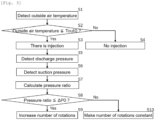
- Fig. 3 is a control flowchart performed by a pressure ratio between discharge pressure and suction pressure in the vapor compression refrigeration cycle device of the embodiment.
- the control device 50 obtains outside air temperature Tout detected by the outside air temperature detecting sensor 44 (S1), and compares the outside air temperature Tout and outside air reference temperature Tout0 (S2).
- the control device 50 opens the second expansion device 21 (S3).
- the control device 50 closes the second expansion device 21 and does not carry out the injection (S4).
- the control device 50 obtains discharge pressure of refrigerant detected by the refrigerant discharge pressure detecting means 41 (S5), obtains suction pressure of refrigerant detected by the refrigerant suction pressure detecting means 42 (S6), and calculates a pressure ratio from the obtained discharge pressure and suction pressure (S7) .
- control device 50 compares the calculated pressure ratio and the reference pressure ratio ⁇ P0 (S8).
- the control device 50 If the calculated pressure ratio is equal to or smaller than the reference pressure ratio ⁇ P0 (Yes in S8), the control device 50 increases the number of rotations of the compressor 11 (S9), and if the calculated pressure ratio is larger than the reference pressure ratio ⁇ P0 (No in S8), the control device 50 constantly maintains the number of rotations of the compressor 11 (S10).
- the control device 50 controls the compressor 11 such that the number of rotations of the compressor 11 is increased, and the control device 50 determines, from the pressure ratio between the discharge pressure and the suction pressure, that the injection amount becomes small , and if the pressure ratio is equal to or smaller than the reference pressure ratio ⁇ P0, necessary heating ability can be obtained by increasing the number of rotations of the compressor 11.
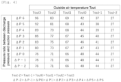
- Fig. 4 is a diagram specifically showing control performed by the pressure ratio between the discharge pressure and suction pressure of refrigerant. Numbers in Fig. 4 show frequencies (Hz) for rotating the compressor 11.
- the outside air temperature Tout has a relation of Tout-2 > Tout-1 > Tout0 > Tout1 > Tout2 > Tout3, and when the outside air temperature Tout is equal to or smaller than outside air reference temperature Tout0, the injection is carried out.
- a set pressure ratio ⁇ P has a relation of ⁇ P-2 > ⁇ P-1 > ⁇ P0 > ⁇ P1 > ⁇ P2 > ⁇ P3 > ⁇ P4 > ⁇ P5 > ⁇ P6, and when the pressure ratio ⁇ P is equal to or smaller than reference pressure ratio ⁇ P0, the number of rotations of the compressor 11 is increased.
- Fig. 4 has a first reference pressure ratio ⁇ P1 which is smaller the reference pressure ratio ⁇ P0, a second reference pressure ratio ⁇ P2 which is smaller than the first reference pressure ratio ⁇ P1, a third reference pressure ratio ⁇ P3 which is smaller than the second reference pressure ratio ⁇ P2, a fourth reference pressure ratio ⁇ P4 which is smaller than the third reference pressure ratio ⁇ P3, a fifth reference pressure ratio ⁇ P5 which is smaller than the fourth reference pressure ratio ⁇ P4, and a sixth reference pressure ratio ⁇ P6 which is smaller than the fifth reference pressure ratio ⁇ P5.
- the number of rotations of the compressor 11 at the first reference pressure ratio ⁇ P1 is made larger than that at the reference pressure ratio ⁇ P0
- the number of rotations of the compressor 11 at the second reference pressure ratio ⁇ P2 is made larger than that at the first reference pressure ratio ⁇ P1
- the number of rotations of the compressor 11 at the third reference pressure ratio ⁇ P3 is made larger than that at the second reference pressure ratio ⁇ P2
- the number of rotations of the compressor 11 at the fourth reference pressure ratio ⁇ P4 is made larger than that at the third reference pressure ratio ⁇ P3
- the number of rotations of the compressor 11 at the fifth reference pressure ratio ⁇ P5 is made larger than that at the fourth reference pressure ratio ⁇ P4
- the number of rotations of the compressor 11 at the sixth reference pressure ratio ⁇ P6 is made larger than that at the fifth reference pressure ratio ⁇ P5.
- the frequency is 66Hz at the first outside air reference temperature Tout1, is 71Hz at the second outside air reference temperature Tout2, and is 76Hz at the third outside air reference temperature Tout3, and those frequencies are made the same as the number of rotations at the reference pressure ratio ⁇ P0.
- the reference pressure ratio there are at least the first reference pressure ratio ⁇ P1 which is smaller than the reference pressure ratio ⁇ P0, and the second reference pressure ratio ⁇ P2 which is smaller than the first reference pressure ratio ⁇ P1.
- the control device 50 makes the number of rotations of the compressor 11 at the second reference pressure ratio ⁇ P2 larger than that of the compressor 11 at the first reference pressure ratio ⁇ P1.
- the control device 50 increases the number of rotations of the compressor 11 in accordance with the compression ratio, thereby maintaining the necessary heating ability.
- the reference temperature of the outside air temperature Tout there are at least first outside air reference temperature Tout1 and second outside air reference temperature Tout 2, and it is preferable that the number of rotations of the compressor 11 at the first reference pressure ratio ⁇ P1 by the second outside air reference temperature Tout2 is made larger than that of the compressor 11 at the first reference pressure ratio ⁇ P1 by the first outside air reference temperature Tout1.
- Fig. 5 is a control flowchart performed by the discharge pressure of refrigerant in the vapor compression refrigeration cycle device of the embodiment.
- the control device 50 obtains outside air temperature Tout detected by the outside air temperature detecting sensor 44 (S1), and compares the outside air temperature Tout and the outside air reference temperature Tout0 with each other (S2).
- the control device 50 opens the second expansion device 21 to carry out the injection (S3).
- the control device 50 closes the second expansion device 21 and does not carry out the injection (S4).
- the control device 50 obtains discharge pressure of refrigerant detected by the refrigerant discharge pressure detecting means 41 (S5), and compares the obtained discharge pressure and the reference pressure P0 with each other (S11).
- the control device 50 increases the number of rotations of the compressor 11 (S9), and if the obtained discharge pressure is higher than the reference pressure P0 (No in S11), the control device 50 constantly maintains the number of rotations of the compressor 11 (S10).
- the control device 50 controls the compressor 11 such that the number of rotations thereof is increased, and the control device 50 determines, from the discharge pressure, that the injection amount becomes small, and if the discharge pressure is equal to or smaller than the reference pressure P0, necessary heating ability can be obtained by increasing the number of rotations of the compressor 11.
- Fig. 6 is a diagram further specifically showing control performed by discharge pressure of refrigerant. Numbers in Fig. 6 show frequencies (Hz) for rotating the compressor 11.
- the outside air temperature Tout has a relation of Tout-2 > Tout-1 > Tout0 > Tout1 > Tout2 > Tout3, and when the outside air temperature Tout is equal to or smaller than the outside air reference temperature Tout0, the injection is carried out.
- the set discharge pressure P has a relation of P-2 > P-1 > P0 > P1 > P2 > P3 > P4 > P5 > P6, and when the discharge pressure P is equal to or smaller than the reference pressure P0, the number of rotations of the compressor 11 is increased.
- Fig. 6 includes first reference pressure P1 which is lower than the reference pressure P0, second reference pressure P2 which is lower than the first reference pressure P1, third reference pressure P3 which is lower than the second reference pressure P2, fourth reference pressure P4 which is lower than the third reference pressure P3, fifth reference pressure P5 which is lower than the fourth reference pressure P4, and sixth reference pressure P6 which is lower than the fifth reference pressure P5.
- the number of rotations of the compressor 11 under the first reference pressure P1 is made larger than that of the compressor 11 under the reference pressure P0
- the number of rotations of the compressor 11 under the second reference pressure P2 is made larger than that of the compressor 11 under the first reference pressure P1
- the number of rotations of the compressor 11 under the third reference pressure P3 is made larger than that of the compressor 11 under the second reference pressure P2
- the number of rotations of the compressor 11 under the fourth reference pressure P4 is made larger than that of the compressor 11 under the third reference pressure P3
- the number of rotations of the compressor 11 under the fifth reference pressure P5 is made larger than that of the compressor 11 under the fourth reference pressure P4
- the number of rotations of the compressor 11 under the sixth pressure P6 is made larger than that of the compressor 11 under the fifth reference pressure P5.
- the frequency is 66Hz at the first outside air reference temperature Tout1, is 71Hz at the second outside air reference temperature Tout2, and is 76Hz at the third outside air reference temperature Tout3, and those frequencies are made the same as the number of rotations under the reference pressure P0.
- the control device 50 makes the number of rotations of the compressor 11 under the second reference pressure P2 larger than that of the compressor 11 under the first reference pressure P1.
- the control device 50 increases the number of rotations of the compressor 11 in accordance with the discharge pressure P, thereby maintaining the necessary heating ability.
- the reference temperature of the outside air temperature Tout there are at least first outside air reference temperature Tout1 and second outside air reference temperature Tout 2, and it is preferable that the number of rotations of the compressor 11 under the first reference pressure P1 by the second outside air reference temperature Tout2 is made larger than that of the compressor 11 under the first reference pressure P1 by the first outside air reference temperature Tout1.
- Fig. 7 is a control flowchart performed by use-side heat medium temperature in the vapor compression refrigeration cycle device of the embodiment.
- the control device 50 obtains outside air temperature Tout detected by the outside air temperature detecting sensor 44 (S1), and compares the outside air temperature Tout and the outside air reference temperature Tout0 with each other (S2).
- the control device 50 opens the second expansion device 21 to carry out the injection (S3).
- the control device 50 closes the second expansion device 21 and does not carry out the injection (S4).
- the control device 50 obtains use-side heat medium temperature detected by the before-heating temperature sensor 43 (S12), and compares the obtained use-side heat medium temperature and the reference temperature Tw0 with each other (S13).
- the control device 50 increases the number of rotations of the compressor 11 (S9), and if the obtained use-side heat medium temperature is higher than the reference temperature Tw0 (No in S13), the control device 50 constantly maintains the number of rotations of the compressor 11 (S10).
- the control device 50 controls the compressor 11 such that the number of rotations thereof is increased, and the control device 50 determines, from the use-side heat medium temperature, that the injection amount becomes small, and if the use-side heat medium temperature is equal to or smaller than the reference temperature Tw0, necessary heating ability can be obtained by increasing the number of rotations of the compressor 11.
- Fig. 8 is a diagram further specifically showing control performed by the use-side heat medium temperature of refrigerant. Numbers in Fig. 8 show frequencies (Hz) for rotating the compressor 11.
- the outside air temperature Tout has a relation of Tout-2 > Tout-1 > Tout0 > Tout1 > Tout2 > Tout3, and when the outside air temperature Tout is equal to or smaller than outside air reference temperature Tout0, the injection is carried out.
- Set temperature Tw has a relation of Tw-2 > Tw-1 > Tw0 > Tw1 > Tw2 > Tw3 > Tw4 > Tw5 > Tw6, and when the set temperature Tw is equal to or smaller than the reference temperature Tw0, the number of rotations of the compressor 11 is increased.
- the number of rotations of the compressor 11 at the first reference temperature Tw1 is made larger than that at the reference temperature Tw0
- the number of rotations of the compressor 11 at the second reference temperature Tw2 is made larger than that at the first reference temperature Tw1
- the number of rotations of the compressor 11 at the third reference temperature Tw3 is made larger than that at the second reference temperature Tw2
- the number of rotations of the compressor 11 at the fourth reference temperature Tw4 is made larger than that at the third reference temperature Tw3
- the number of rotations of the compressor 11 at the fifth reference temperature Tw5 is made larger than that at the fourth reference temperature Tw4
- the number of rotations of the compressor 11 at the sixth reference temperature Tw6 is made larger than that at the fifth reference temperature Tw5.
- the control device 50 makes the number of rotations of the compressor 11 at the second reference temperature Tw2 larger than that of the compressor 11 at the first reference temperature Tw1.
- the control device 50 increases the number of rotations of the compressor 11 in accordance with the use-side heat medium temperature, thereby maintaining the necessary heating ability.
- the reference temperature of the outside air temperature Tout there are at least first outside air reference temperature Tout1 and second outside air reference temperature Tout 2, and it is preferable that the number of rotations of the compressor 11 at the first reference temperature Tw1 by the second outside air reference temperature Tout2 is made larger than that of the compressor 11 at the first reference temperature Tw1 by the first outside air reference temperature Tout1.
Landscapes
- Engineering & Computer Science (AREA)
- Physics & Mathematics (AREA)
- Mechanical Engineering (AREA)
- Thermal Sciences (AREA)
- General Engineering & Computer Science (AREA)
- Compression-Type Refrigeration Machines With Reversible Cycles (AREA)
- Air Conditioning Control Device (AREA)
- Applications Or Details Of Rotary Compressors (AREA)
Applications Claiming Priority (1)
| Application Number | Priority Date | Filing Date | Title |
|---|---|---|---|
| JP2022190326A JP2024078027A (ja) | 2022-11-29 | 2022-11-29 | 蒸気圧縮式冷凍サイクル装置 |
Publications (1)
| Publication Number | Publication Date |
|---|---|
| EP4382832A1 true EP4382832A1 (de) | 2024-06-12 |
Family
ID=88975409
Family Applications (1)
| Application Number | Title | Priority Date | Filing Date |
|---|---|---|---|
| EP23212256.4A Pending EP4382832A1 (de) | 2022-11-29 | 2023-11-27 | Dampfkompressionskühlzyklusvorrichtung |
Country Status (4)
| Country | Link |
|---|---|
| US (1) | US12442574B2 (de) |
| EP (1) | EP4382832A1 (de) |
| JP (1) | JP2024078027A (de) |
| CN (1) | CN118111133A (de) |
Citations (6)
| Publication number | Priority date | Publication date | Assignee | Title |
|---|---|---|---|---|
| JP2008008499A (ja) * | 2006-06-27 | 2008-01-17 | Sanyo Electric Co Ltd | 冷凍サイクル装置及びヒートポンプ式給湯機 |
| EP2535674A2 (de) * | 2011-06-17 | 2012-12-19 | Panasonic Corporation | Kältekreislaufvorrichtung und hydronisches Heizgerät mit Kältekreislaufvorrichtung |
| JP2014190632A (ja) * | 2013-03-27 | 2014-10-06 | Hitachi Appliances Inc | 空気調和機、および空気調和機の運転方法 |
| EP2924369A1 (de) * | 2014-03-20 | 2015-09-30 | LG Electronics Inc. | Klimaanlage und verfahren zur steuerung einer klimaanlage |
| EP3730875A1 (de) | 2018-01-25 | 2020-10-28 | Samsung Electronics Co., Ltd. | Klimaanlage und steuerungsverfahren dafür |
| WO2022201361A1 (ja) * | 2021-03-24 | 2022-09-29 | 東芝キヤリア株式会社 | 冷凍サイクル装置 |
Family Cites Families (2)
| Publication number | Priority date | Publication date | Assignee | Title |
|---|---|---|---|---|
| JP2008248865A (ja) * | 2007-03-30 | 2008-10-16 | Fujitsu General Ltd | インジェクション対応2段圧縮ロータリ圧縮機およびヒートポンプシステム |
| KR101983697B1 (ko) * | 2013-09-23 | 2019-06-04 | 한온시스템 주식회사 | 차량용 히트 펌프 시스템의 전동 압축기 제어 방법 |
-
2022
- 2022-11-29 JP JP2022190326A patent/JP2024078027A/ja active Pending
-
2023
- 2023-10-06 US US18/482,566 patent/US12442574B2/en active Active
- 2023-11-22 CN CN202311559497.6A patent/CN118111133A/zh active Pending
- 2023-11-27 EP EP23212256.4A patent/EP4382832A1/de active Pending
Patent Citations (7)
| Publication number | Priority date | Publication date | Assignee | Title |
|---|---|---|---|---|
| JP2008008499A (ja) * | 2006-06-27 | 2008-01-17 | Sanyo Electric Co Ltd | 冷凍サイクル装置及びヒートポンプ式給湯機 |
| EP2535674A2 (de) * | 2011-06-17 | 2012-12-19 | Panasonic Corporation | Kältekreislaufvorrichtung und hydronisches Heizgerät mit Kältekreislaufvorrichtung |
| JP2014190632A (ja) * | 2013-03-27 | 2014-10-06 | Hitachi Appliances Inc | 空気調和機、および空気調和機の運転方法 |
| EP2924369A1 (de) * | 2014-03-20 | 2015-09-30 | LG Electronics Inc. | Klimaanlage und verfahren zur steuerung einer klimaanlage |
| EP3730875A1 (de) | 2018-01-25 | 2020-10-28 | Samsung Electronics Co., Ltd. | Klimaanlage und steuerungsverfahren dafür |
| WO2022201361A1 (ja) * | 2021-03-24 | 2022-09-29 | 東芝キヤリア株式会社 | 冷凍サイクル装置 |
| US20240011689A1 (en) * | 2021-03-24 | 2024-01-11 | Toshiba Carrier Corporation | Refrigeration cycle apparatus |
Also Published As
| Publication number | Publication date |
|---|---|
| JP2024078027A (ja) | 2024-06-10 |
| CN118111133A (zh) | 2024-05-31 |
| US20240175615A1 (en) | 2024-05-30 |
| US12442574B2 (en) | 2025-10-14 |
Similar Documents
| Publication | Publication Date | Title |
|---|---|---|
| CN112963986B (zh) | 制冷循环装置 | |
| JP5627713B2 (ja) | 空気調和装置 | |
| EP2275757B1 (de) | Luftklimatisierungs- und heisswasserkomplexsystem | |
| KR101003228B1 (ko) | 냉동장치 | |
| JP5968534B2 (ja) | 空気調和装置 | |
| JP5871959B2 (ja) | 空気調和装置 | |
| EP2508821B1 (de) | Kältekreislaufvorrichtung und hydronisches Heizgerät mit Kältekreislaufvorrichtung | |
| EP2535674B1 (de) | Kältekreislaufvorrichtung und hydronisches Heizgerät mit Kältekreislaufvorrichtung | |
| EP2792974B1 (de) | Klimaanlage und Steuerverfahren dafür | |
| EP2933583A1 (de) | Erwärmungsvorrichtung mit einer wärmepumpe | |
| EP2924375A1 (de) | Kältekreislaufvorrichtung und warmwaterbereitungsvorrichtung damit | |
| CN113710971A (zh) | 空气调节装置 | |
| CN104185766A (zh) | 热泵式加热装置 | |
| EP2853838A1 (de) | Heißwassererzeuger | |
| CN118922677A (zh) | 空气调节装置 | |
| EP3805663A1 (de) | Superkritischer dampfkompressionskältekreislauf und flüssigkeitserhitzer | |
| EP2918921B1 (de) | Heisswassererzeuger | |
| US12442574B2 (en) | Vapor compression refrigeration cycle device | |
| EP3683520B1 (de) | Kältekreislaufvorrichtung und flüssigkeitsheizvorrichtung damit | |
| EP3677855B1 (de) | Kältekreislaufvorrichtung und flüssigkeitserhitzungsvorrichtung damit | |
| EP3696478B1 (de) | Wärmepumpensystem | |
| EP3671049B1 (de) | Wärmepumpensystem | |
| EP3835687B1 (de) | Wärmepumpe | |
| EP4379288A1 (de) | Dampfkompressionskühlzyklusvorrichtung | |
| EP3736514A1 (de) | Kältekreislaufvorrichtung und flüssigkeitsheizvorrichtung damit |
Legal Events
| Date | Code | Title | Description |
|---|---|---|---|
| PUAI | Public reference made under article 153(3) epc to a published international application that has entered the european phase |
Free format text: ORIGINAL CODE: 0009012 |
|
| STAA | Information on the status of an ep patent application or granted ep patent |
Free format text: STATUS: THE APPLICATION HAS BEEN PUBLISHED |
|
| AK | Designated contracting states |
Kind code of ref document: A1 Designated state(s): AL AT BE BG CH CY CZ DE DK EE ES FI FR GB GR HR HU IE IS IT LI LT LU LV MC ME MK MT NL NO PL PT RO RS SE SI SK SM TR |
|
| STAA | Information on the status of an ep patent application or granted ep patent |
Free format text: STATUS: REQUEST FOR EXAMINATION WAS MADE |
|
| 17P | Request for examination filed |
Effective date: 20241212 |
|
| STAA | Information on the status of an ep patent application or granted ep patent |
Free format text: STATUS: EXAMINATION IS IN PROGRESS |
|
| 17Q | First examination report despatched |
Effective date: 20251121 |