EP4382828A1 - Refrigeration circuit device and control method for refrigeration circuit device - Google Patents
Refrigeration circuit device and control method for refrigeration circuit device Download PDFInfo
- Publication number
- EP4382828A1 EP4382828A1 EP21952786.8A EP21952786A EP4382828A1 EP 4382828 A1 EP4382828 A1 EP 4382828A1 EP 21952786 A EP21952786 A EP 21952786A EP 4382828 A1 EP4382828 A1 EP 4382828A1
- Authority
- EP
- European Patent Office
- Prior art keywords
- low
- stage
- refrigerant
- stage circuit
- pressure
- Prior art date
- Legal status (The legal status is an assumption and is not a legal conclusion. Google has not performed a legal analysis and makes no representation as to the accuracy of the status listed.)
- Withdrawn
Links
Images




Classifications
-
- F—MECHANICAL ENGINEERING; LIGHTING; HEATING; WEAPONS; BLASTING
- F25—REFRIGERATION OR COOLING; COMBINED HEATING AND REFRIGERATION SYSTEMS; HEAT PUMP SYSTEMS; MANUFACTURE OR STORAGE OF ICE; LIQUEFACTION SOLIDIFICATION OF GASES
- F25B—REFRIGERATION MACHINES, PLANTS OR SYSTEMS; COMBINED HEATING AND REFRIGERATION SYSTEMS; HEAT PUMP SYSTEMS
- F25B1/00—Compression machines, plants or systems with non-reversible cycle
- F25B1/005—Compression machines, plants or systems with non-reversible cycle of the single unit type
-
- F—MECHANICAL ENGINEERING; LIGHTING; HEATING; WEAPONS; BLASTING
- F25—REFRIGERATION OR COOLING; COMBINED HEATING AND REFRIGERATION SYSTEMS; HEAT PUMP SYSTEMS; MANUFACTURE OR STORAGE OF ICE; LIQUEFACTION SOLIDIFICATION OF GASES
- F25B—REFRIGERATION MACHINES, PLANTS OR SYSTEMS; COMBINED HEATING AND REFRIGERATION SYSTEMS; HEAT PUMP SYSTEMS
- F25B25/00—Machines, plants or systems, using a combination of modes of operation covered by two or more of the groups F25B1/00 - F25B23/00
- F25B25/005—Machines, plants or systems, using a combination of modes of operation covered by two or more of the groups F25B1/00 - F25B23/00 using primary and secondary systems
-
- F—MECHANICAL ENGINEERING; LIGHTING; HEATING; WEAPONS; BLASTING
- F25—REFRIGERATION OR COOLING; COMBINED HEATING AND REFRIGERATION SYSTEMS; HEAT PUMP SYSTEMS; MANUFACTURE OR STORAGE OF ICE; LIQUEFACTION SOLIDIFICATION OF GASES
- F25B—REFRIGERATION MACHINES, PLANTS OR SYSTEMS; COMBINED HEATING AND REFRIGERATION SYSTEMS; HEAT PUMP SYSTEMS
- F25B43/00—Arrangements for separating or purifying gases or liquids; Arrangements for vaporising the residuum of liquid refrigerant, e.g. by heat
- F25B43/006—Accumulators
-
- F—MECHANICAL ENGINEERING; LIGHTING; HEATING; WEAPONS; BLASTING
- F25—REFRIGERATION OR COOLING; COMBINED HEATING AND REFRIGERATION SYSTEMS; HEAT PUMP SYSTEMS; MANUFACTURE OR STORAGE OF ICE; LIQUEFACTION SOLIDIFICATION OF GASES
- F25B—REFRIGERATION MACHINES, PLANTS OR SYSTEMS; COMBINED HEATING AND REFRIGERATION SYSTEMS; HEAT PUMP SYSTEMS
- F25B49/00—Arrangement or mounting of control or safety devices
- F25B49/005—Arrangement or mounting of control or safety devices of safety devices
-
- F—MECHANICAL ENGINEERING; LIGHTING; HEATING; WEAPONS; BLASTING
- F25—REFRIGERATION OR COOLING; COMBINED HEATING AND REFRIGERATION SYSTEMS; HEAT PUMP SYSTEMS; MANUFACTURE OR STORAGE OF ICE; LIQUEFACTION SOLIDIFICATION OF GASES
- F25B—REFRIGERATION MACHINES, PLANTS OR SYSTEMS; COMBINED HEATING AND REFRIGERATION SYSTEMS; HEAT PUMP SYSTEMS
- F25B49/00—Arrangement or mounting of control or safety devices
- F25B49/02—Arrangement or mounting of control or safety devices for compression type machines, plants or systems
-
- F—MECHANICAL ENGINEERING; LIGHTING; HEATING; WEAPONS; BLASTING
- F25—REFRIGERATION OR COOLING; COMBINED HEATING AND REFRIGERATION SYSTEMS; HEAT PUMP SYSTEMS; MANUFACTURE OR STORAGE OF ICE; LIQUEFACTION SOLIDIFICATION OF GASES
- F25B—REFRIGERATION MACHINES, PLANTS OR SYSTEMS; COMBINED HEATING AND REFRIGERATION SYSTEMS; HEAT PUMP SYSTEMS
- F25B49/00—Arrangement or mounting of control or safety devices
- F25B49/02—Arrangement or mounting of control or safety devices for compression type machines, plants or systems
- F25B49/022—Compressor control arrangements
-
- F—MECHANICAL ENGINEERING; LIGHTING; HEATING; WEAPONS; BLASTING
- F25—REFRIGERATION OR COOLING; COMBINED HEATING AND REFRIGERATION SYSTEMS; HEAT PUMP SYSTEMS; MANUFACTURE OR STORAGE OF ICE; LIQUEFACTION SOLIDIFICATION OF GASES
- F25B—REFRIGERATION MACHINES, PLANTS OR SYSTEMS; COMBINED HEATING AND REFRIGERATION SYSTEMS; HEAT PUMP SYSTEMS
- F25B7/00—Compression machines, plants or systems, with cascade operation, i.e. with two or more circuits, the heat from the condenser of one circuit being absorbed by the evaporator of the next circuit
-
- F—MECHANICAL ENGINEERING; LIGHTING; HEATING; WEAPONS; BLASTING
- F25—REFRIGERATION OR COOLING; COMBINED HEATING AND REFRIGERATION SYSTEMS; HEAT PUMP SYSTEMS; MANUFACTURE OR STORAGE OF ICE; LIQUEFACTION SOLIDIFICATION OF GASES
- F25B—REFRIGERATION MACHINES, PLANTS OR SYSTEMS; COMBINED HEATING AND REFRIGERATION SYSTEMS; HEAT PUMP SYSTEMS
- F25B9/00—Compression machines, plants or systems, in which the refrigerant is air or other gas of low boiling point
- F25B9/002—Compression machines, plants or systems, in which the refrigerant is air or other gas of low boiling point characterised by the refrigerant
- F25B9/006—Compression machines, plants or systems, in which the refrigerant is air or other gas of low boiling point characterised by the refrigerant the refrigerant containing more than one component
-
- F—MECHANICAL ENGINEERING; LIGHTING; HEATING; WEAPONS; BLASTING
- F25—REFRIGERATION OR COOLING; COMBINED HEATING AND REFRIGERATION SYSTEMS; HEAT PUMP SYSTEMS; MANUFACTURE OR STORAGE OF ICE; LIQUEFACTION SOLIDIFICATION OF GASES
- F25B—REFRIGERATION MACHINES, PLANTS OR SYSTEMS; COMBINED HEATING AND REFRIGERATION SYSTEMS; HEAT PUMP SYSTEMS
- F25B2400/00—Component parts or details not otherwise provided for in this subclass
- F25B2400/19—Pumping down refrigerant from one part of the cycle to another part of the cycle, e.g. when the cycle is changed from cooling to heating, or before a defrost cycle is started
-
- F—MECHANICAL ENGINEERING; LIGHTING; HEATING; WEAPONS; BLASTING
- F25—REFRIGERATION OR COOLING; COMBINED HEATING AND REFRIGERATION SYSTEMS; HEAT PUMP SYSTEMS; MANUFACTURE OR STORAGE OF ICE; LIQUEFACTION SOLIDIFICATION OF GASES
- F25B—REFRIGERATION MACHINES, PLANTS OR SYSTEMS; COMBINED HEATING AND REFRIGERATION SYSTEMS; HEAT PUMP SYSTEMS
- F25B2400/00—Component parts or details not otherwise provided for in this subclass
- F25B2400/22—Refrigeration systems for supermarkets
-
- F—MECHANICAL ENGINEERING; LIGHTING; HEATING; WEAPONS; BLASTING
- F25—REFRIGERATION OR COOLING; COMBINED HEATING AND REFRIGERATION SYSTEMS; HEAT PUMP SYSTEMS; MANUFACTURE OR STORAGE OF ICE; LIQUEFACTION SOLIDIFICATION OF GASES
- F25B—REFRIGERATION MACHINES, PLANTS OR SYSTEMS; COMBINED HEATING AND REFRIGERATION SYSTEMS; HEAT PUMP SYSTEMS
- F25B2500/00—Problems to be solved
- F25B2500/07—Exceeding a certain pressure value in a refrigeration component or cycle
-
- F—MECHANICAL ENGINEERING; LIGHTING; HEATING; WEAPONS; BLASTING
- F25—REFRIGERATION OR COOLING; COMBINED HEATING AND REFRIGERATION SYSTEMS; HEAT PUMP SYSTEMS; MANUFACTURE OR STORAGE OF ICE; LIQUEFACTION SOLIDIFICATION OF GASES
- F25B—REFRIGERATION MACHINES, PLANTS OR SYSTEMS; COMBINED HEATING AND REFRIGERATION SYSTEMS; HEAT PUMP SYSTEMS
- F25B2500/00—Problems to be solved
- F25B2500/27—Problems to be solved characterised by the stop of the refrigeration cycle
-
- F—MECHANICAL ENGINEERING; LIGHTING; HEATING; WEAPONS; BLASTING
- F25—REFRIGERATION OR COOLING; COMBINED HEATING AND REFRIGERATION SYSTEMS; HEAT PUMP SYSTEMS; MANUFACTURE OR STORAGE OF ICE; LIQUEFACTION SOLIDIFICATION OF GASES
- F25B—REFRIGERATION MACHINES, PLANTS OR SYSTEMS; COMBINED HEATING AND REFRIGERATION SYSTEMS; HEAT PUMP SYSTEMS
- F25B2600/00—Control issues
- F25B2600/02—Compressor control
- F25B2600/025—Compressor control by controlling speed
- F25B2600/0253—Compressor control by controlling speed with variable speed
-
- F—MECHANICAL ENGINEERING; LIGHTING; HEATING; WEAPONS; BLASTING
- F25—REFRIGERATION OR COOLING; COMBINED HEATING AND REFRIGERATION SYSTEMS; HEAT PUMP SYSTEMS; MANUFACTURE OR STORAGE OF ICE; LIQUEFACTION SOLIDIFICATION OF GASES
- F25B—REFRIGERATION MACHINES, PLANTS OR SYSTEMS; COMBINED HEATING AND REFRIGERATION SYSTEMS; HEAT PUMP SYSTEMS
- F25B2600/00—Control issues
- F25B2600/11—Fan speed control
- F25B2600/111—Fan speed control of condenser fans
-
- F—MECHANICAL ENGINEERING; LIGHTING; HEATING; WEAPONS; BLASTING
- F25—REFRIGERATION OR COOLING; COMBINED HEATING AND REFRIGERATION SYSTEMS; HEAT PUMP SYSTEMS; MANUFACTURE OR STORAGE OF ICE; LIQUEFACTION SOLIDIFICATION OF GASES
- F25B—REFRIGERATION MACHINES, PLANTS OR SYSTEMS; COMBINED HEATING AND REFRIGERATION SYSTEMS; HEAT PUMP SYSTEMS
- F25B2600/00—Control issues
- F25B2600/25—Control of valves
- F25B2600/2513—Expansion valves
-
- F—MECHANICAL ENGINEERING; LIGHTING; HEATING; WEAPONS; BLASTING
- F25—REFRIGERATION OR COOLING; COMBINED HEATING AND REFRIGERATION SYSTEMS; HEAT PUMP SYSTEMS; MANUFACTURE OR STORAGE OF ICE; LIQUEFACTION SOLIDIFICATION OF GASES
- F25B—REFRIGERATION MACHINES, PLANTS OR SYSTEMS; COMBINED HEATING AND REFRIGERATION SYSTEMS; HEAT PUMP SYSTEMS
- F25B2600/00—Control issues
- F25B2600/25—Control of valves
- F25B2600/2525—Pressure relief valves
-
- F—MECHANICAL ENGINEERING; LIGHTING; HEATING; WEAPONS; BLASTING
- F25—REFRIGERATION OR COOLING; COMBINED HEATING AND REFRIGERATION SYSTEMS; HEAT PUMP SYSTEMS; MANUFACTURE OR STORAGE OF ICE; LIQUEFACTION SOLIDIFICATION OF GASES
- F25B—REFRIGERATION MACHINES, PLANTS OR SYSTEMS; COMBINED HEATING AND REFRIGERATION SYSTEMS; HEAT PUMP SYSTEMS
- F25B2700/00—Sensing or detecting of parameters; Sensors therefor
- F25B2700/19—Pressures
- F25B2700/193—Pressures of the compressor
- F25B2700/1931—Discharge pressures
-
- F—MECHANICAL ENGINEERING; LIGHTING; HEATING; WEAPONS; BLASTING
- F25—REFRIGERATION OR COOLING; COMBINED HEATING AND REFRIGERATION SYSTEMS; HEAT PUMP SYSTEMS; MANUFACTURE OR STORAGE OF ICE; LIQUEFACTION SOLIDIFICATION OF GASES
- F25B—REFRIGERATION MACHINES, PLANTS OR SYSTEMS; COMBINED HEATING AND REFRIGERATION SYSTEMS; HEAT PUMP SYSTEMS
- F25B2700/00—Sensing or detecting of parameters; Sensors therefor
- F25B2700/19—Pressures
- F25B2700/195—Pressures of the condenser
Definitions
- the present disclosure relates to a refrigeration cycle apparatus provided with a two-stage refrigeration cycle, and also relates to a method for controlling the refrigeration cycle apparatus.
- a refrigeration apparatus including a low-stage circuit through which a low-stage refrigerant circulates, a high-stage circuit through which a high-stage refrigerant circulates, and a cascade condenser configured to exchange heat between the low-stage refrigerant and the high-stage refrigerant has been known (for example, Patent Literature 1).
- Patent Literature 1 International Publication No. WO 2014030236
- a zeotropic refrigerant mixture is used as a low-stage refrigerant that circulates in the low-stage circuit.
- refrigerant having a low-boiling-point contained in the zeotropic refrigerant mixture is gasified and remains in the low-stage circuit in its entirety, which may vary the composition of liquid refrigerant.
- the low-stage circuit includes a welding portion of pipes, if the gasified refrigerant leaks from the welding portion, the leakage leads to significant variations in the composition of the liquid refrigerant.
- the present disclosure has been made to solve the above problems, and it is an object of the present disclosure to provide a refrigeration cycle apparatus and a method for controlling the refrigeration cycle apparatus that can reduce variations in composition of refrigerant after stopping operation of a low-stage circuit.
- a refrigeration cycle apparatus includes: a high-stage circuit through which a high-stage refrigerant circulates, the high-stage circuit including a first compressor, a condenser, a first expansion device, and a cascade heat exchanger; and a low-stage circuit through which a low-stage refrigerant circulates, the low-stage circuit including a second compressor, the cascade heat exchanger, a second expansion device, and an evaporator, wherein the cascade heat exchanger is configured to exchange heat between the high-stage refrigerant and the low-stage refrigerant, the low-stage refrigerant is a zeotropic refrigerant mixture, and pressure of the low-stage refrigerant in the low-stage circuit after deactivating the second compressor is maintained to be equal to or lower than a pressure at or below which the low-stage refrigerant is non-flammable.
- a method for controlling a refrigeration cycle apparatus is a method for controlling a refrigeration cycle apparatus, the refrigeration cycle apparatus including a high-stage circuit through which a high-stage refrigerant circulates and a low-stage circuit through which a low-stage refrigerant circulates, the high-stage circuit including a first compressor, a condenser, a first expansion device, and a cascade heat exchanger, the low-stage circuit including a second compressor, the cascade heat exchanger, a second expansion device, and an evaporator, the cascade heat exchanger being configured to exchange heat between the high-stage refrigerant and the low-stage refrigerant, the low-stage refrigerant being a zeotropic refrigerant mixture, the method including maintaining pressure of the low-stage refrigerant in the low-stage circuit after deactivating the second compressor to be equal to or lower than a pressure at or below which the low-stage refrigerant is non-flammable.
- the pressure of the low-stage refrigerant in the low-stage circuit after deactivating the second compressor is maintained to be equal to or lower than a pressure at or below which the low-stage refrigerant is non-flammable, so that it is possible to reduce variations in composition of the refrigerant after stopping operation of the low-stage circuit.
- a refrigeration cycle apparatus 100 according to Embodiment 1 is described below.
- the refrigeration cycle apparatus 100 is provided with a two-stage refrigeration cycle in which refrigerant circulates independently in each refrigerant cycle.
- the refrigeration cycle apparatus 100 is used for various purposes such as freezing, refrigeration, hot-water supply, or air-conditioning.
- an example is described in which the refrigeration cycle apparatus 100 is used as a refrigeration apparatus configured to cool a freezer compartment or the like.
- Fig. 1 is a schematic configuration diagram of the refrigeration cycle apparatus 100 according to Embodiment 1.
- the refrigeration cycle apparatus 100 in the present embodiment includes a high-stage circuit 1, a low-stage circuit 2, and a controller 3.
- the high-stage circuit 1 is a high-temperature circuit through which a high-stage refrigerant circulates.
- the low-stage circuit 2 is a lowtemperature circuit through which a low-stage refrigerant circulates.
- the low-stage refrigerant has a boiling point lower than that of the high-stage refrigerant.
- the high-stage circuit 1 and the low-stage circuit 2 include a cascade heat exchanger 14 that is shared between them. Through the cascade heat exchanger 14, the high-stage refrigerant circulating in the high-stage circuit 1 exchanges heat with the low-stage refrigerant circulating in the low-stage circuit 2.
- the high-stage circuit 1 includes a first compressor 11, a condenser 12, a first expansion device 13, and the cascade heat exchanger 14.
- the first compressor 11, the condenser 12, the first expansion device 13, and the cascade heat exchanger 14 are connected in this order by pipes.
- Examples of the high-stage refrigerant circulating in the high-stage circuit 1 include an HFC-based single refrigerant such as R134a, R32, or R410A, a refrigerant mixture thereof, an HFO-based single refrigerant such as HFO-1234yf, and a refrigerant mixture thereof.
- the first compressor 11 is, for example, an inverter-type compressor whose capacity is controllable.
- the first compressor 11 suctions a high-stage refrigerant, compresses the suctioned high-stage refrigerant into a high-temperature high-pressure state, and discharges the compressed high-stage refrigerant to be circulated in the high-stage circuit 1.
- the condenser 12 is, for example, a fin-and-tube heat exchanger.
- the condenser 12 is configured to exchange heat between air and a high-stage refrigerant, and condense and liquefy the high-stage refrigerant.
- the refrigeration cycle apparatus 100 includes a first fan 15 for supplying air to the condenser 12. Examples of the first fan 15 include a propeller fan and a cross flow fan whose airflow volume is controllable.
- the condenser 12 may be, for example, a plate heat exchanger configured to exchange heat between water or brine and the high-stage refrigerant. In this case, the first fan 15 may be omitted.
- the first expansion device 13 is, for example, an electronic expansion valve whose opening degree is controllable.
- the first expansion device 13 is connected to the condenser 12 to reduce a pressure of the high-stage refrigerant flowing out from the condenser 12 and expand the high-stage refrigerant.
- the first expansion device 13 may be a capillary tube or a thermostatic expansion valve.
- the cascade heat exchanger 14 is, for example, a plate heat exchanger.
- the cascade heat exchanger 14 includes a high-stage flow passage 141 connected to the high-stage circuit 1, and a low-stage flow passage 142 connected to the low-stage circuit 2.
- the cascade heat exchanger 14 is configured to exchange heat between the high-stage refrigerant flowing through the high-stage flow passage 141 and the low-stage refrigerant flowing through the low-stage flow passage 142.
- the high-stage flow passage 141 in the cascade heat exchanger 14 serves as an evaporator to evaporate and gasify the high-stage refrigerant.
- the low-stage flow passage 142 in the cascade heat exchanger 14 serves as a condenser to condense and liquefy the low-stage refrigerant.
- the low-stage circuit 2 includes a second compressor 21, the cascade heat exchanger 14, a second expansion device 23, and an evaporator 24.
- the second compressor 21, the cascade heat exchanger 14, the second expansion device 23, and the evaporator 24 are connected in this order by pipes.
- the low-stage refrigerant circulating in the low-stage circuit 2 is a zeotropic refrigerant mixture having a boiling point lower than that of the high-stage refrigerant. A lower evaporating temperature can be obtained by using the zeotropic refrigerant mixture, compared to the evaporating temperature obtained by using a single refrigerant.
- a zeotropic refrigerant mixture containing CO 2 and R290 (propane) is used as the low-stage refrigerant.
- CO 2 is refrigerant having a low-boiling-point
- R290 is refrigerant having a high-boiling-point whose boiling point is higher than that of CO 2 . It is possible to decrease an environmental load by using natural refrigerants such as CO 2 and R290. Mixing CO 2 into the low-stage refrigerant leads to an improvement in the cooling capacity, while mixing R290 into the low-stage refrigerant leads to an improvement in COP and to a decrease in triple point of CO 2 , which allows applications in low temperature.
- the second compressor 21 is, for example, an inverter-type compressor whose capacity is controllable.
- the second compressor 21 suctions the low-stage refrigerant, compresses the suctioned low-stage refrigerant into a high-temperature high-pressure state, and discharges the compressed low-stage refrigerant to be circulated in the low-stage circuit 2.
- the second expansion device 23 is, for example, an electronic expansion valve whose opening degree is controllable.
- the second expansion device 23 is connected to the low-stage flow passage 142 in the cascade heat exchanger 14 to reduce the pressure of the low-stage refrigerant flowing out from the low-stage flow passage 142 and expand the low-stage refrigerant.
- the second expansion device 23 may be a capillary tube or a thermostatic expansion valve.
- the evaporator 24 is, for example, a fin-and-tube heat exchanger.
- the evaporator 24 is configured to exchange heat between air and the low-stage refrigerant, and evaporate and gasify the low-stage refrigerant.
- the refrigeration cycle apparatus 100 includes a second fan 25 configured to supply air to the evaporator 24.
- the second fan 25 include a propeller fan and a cross flow fan whose airflow volume is controllable.
- the evaporator 24 may be, for example, a plate heat exchanger configured to exchange heat between water or brine and the low-stage refrigerant. In this case, the second fan 25 may be omitted.
- the refrigeration cycle apparatus 100 includes a pressure sensor 26 configured to detect a pressure P of the low-stage refrigerant in the low-stage circuit 2 during a stop of operation of the low-stage circuit 2. Since the pressure P of the low-stage refrigerant during a stop of operation of the low-stage circuit 2 is substantially uniform in the low-stage circuit 2, the pressure sensor 26 is provided at any location in the low-stage circuit 2. In the example illustrated in Fig. 1 , the pressure sensor 26 is provided on a pipe connecting the low-stage flow passage 142 in the cascade heat exchanger 14 and the second expansion device 23. The pressure P of the low-stage refrigerant detected by the pressure sensor 26 is transmitted to the controller 3.
- the refrigeration cycle apparatus 100 may include a sensor configured to detect any other physical quantity (for example, condensing temperature) that is convertible to the pressure P of the low-stage refrigerant, such that the controller 3 converts the detected physical quantity to the pressure P.
- the refrigeration cycle apparatus 100 may further include various types of sensors (not illustrated) such as an outside-air temperature sensor configured to detect an outside-air temperature, a room temperature sensor configured to detect a temperature in the freezer compartment, or a sensor configured to detect a refrigerant temperature or pressure at any location in the high-stage circuit 1 and the low-stage circuit 2.
- the controller 3 controls operation of the refrigeration cycle apparatus 100 in its entirety.
- the controller 3 is constituted by a processing device including a memory configured to store data and programs necessary for controlling the operation, and a CPU configured to execute the programs, or is constituted by dedicated hardware such as ASIC or FPGA or by both the processing device and the dedicated hardware.
- the controller 3 in the present embodiment controls the high-stage circuit 1 based on the pressure P of the low-stage refrigerant detected by the pressure sensor 26 when operation of the low-stage circuit 2 is stopped.
- the controller 3 controls the respective devices in the high-stage circuit 1 and the low-stage circuit 2 as well as the first fan 15 and the second fan 25 based on the information received from the various types of sensors and an operating instruction given by a user.
- Operation of the refrigeration cycle apparatus 100 in the present embodiment is described below based on a flow of refrigerant circulating in each refrigerant circuit.
- operation of the high-stage circuit 1 is described.
- the first compressor 11 and the second compressor 21 are driven upon receiving an instruction to start operation of the refrigeration cycle apparatus 100.
- the first compressor 11 in the high-stage circuit 1 suctions the high-stage refrigerant, compresses the suctioned high-stage refrigerant into a high-temperature high-pressure state, and discharges the compressed high-stage refrigerant.
- the high-stage refrigerant discharged from the first compressor 11 flows into the condenser 12.
- the condenser 12 is configured to exchange heat between air supplied by the first fan 15 and the high-stage refrigerant, and condenses and liquefies the high-stage refrigerant.
- the high-stage refrigerant condensed and liquefied through the condenser 12 passes through the first expansion device 13.
- the first expansion device 13 reduces the pressure of the condensed and liquefied high-stage refrigerant.
- the high-stage refrigerant with its pressure reduced by the first expansion device 13 flows into the high-stage flow passage 141 in the cascade heat exchanger 14.
- the high-stage refrigerant flowing into the high-stage flow passage 141 exchanges heat with the low-stage refrigerant flowing through the low-stage flow passage 142 in the cascade heat exchanger 14, and is thus evaporated and gasified.
- the high-stage refrigerant evaporated and gasified through the cascade heat exchanger 14 is suctioned into the first compressor 11 again.
- the second compressor 21 in the low-stage circuit 2 suctions the low-stage refrigerant, compresses the suctioned low-stage refrigerant into a high-temperature high-pressure state, and discharges the compressed low-stage refrigerant.
- the low-stage refrigerant discharged from the second compressor 21 flows into the low-stage flow passage 142 in the cascade heat exchanger 14.
- the low-stage refrigerant flowing into the low-stage flow passage 142 exchanges heat with the high-stage refrigerant flowing through the high-stage flow passage 141 in the cascade heat exchanger 14, and is thus condensed and liquefied.
- the low-stage refrigerant condensed and liquefied through the cascade heat exchanger 14 passes through the second expansion device 23.
- the second expansion device 23 reduces the pressure of the low-stage refrigerant.
- the low-stage refrigerant with its pressure reduced by the second expansion device 23 flows into the evaporator 24.
- the evaporator 24 is configured to exchange heat between air supplied by the second fan 25 and the low-stage refrigerant, and evaporates and gasifies the low-stage refrigerant. At this time, the low-stage refrigerant removes heat from the air, so that the freezer compartment is cooled.
- the low-stage refrigerant evaporated and gasified through the evaporator 24 is suctioned into the second compressor 21 again.
- the first compressor 11 and the second compressor 21 Upon receiving an instruction to stop operation of the refrigeration cycle apparatus 100, the first compressor 11 and the second compressor 21 is deactivated, and refrigerant stops circulating in the high-stage circuit 1 and the low-stage circuit 2. At this time, the refrigerant having a low-boiling-point contained in the low-stage refrigerant in the low-stage circuit 2 in its entirety is gasified, which varies the composition of liquid refrigerant in the low-stage circuit 2.
- the evaporator 24 in the low-stage circuit 2 is located in a room such as a freezer compartment and connected to the second compressor 21 by an extension pipe. Due to this structure, on the suction side of the second compressor 21, a welding portion connected to the extension pipe is provided. If the CO 2 gas leaks from the welding portion when the operation of the low-stage circuit 2 is stopped, the ratio of R290 that is a flammable refrigerant further increases in the liquid refrigerant in the low-stage circuit 2. This results in an increase in the flammability of the low-stage refrigerant in the low-stage circuit 2, and accordingly an increase in the risk due to the flammability at the time of refrigerant leakage.
- the controller 3 in the present embodiment continues operation of the high-stage circuit 1 even after stopping the operation of the low-stage circuit 2, and controls the capacity of the high-stage circuit 1 to cause the pressure P of the low-stage refrigerant to be equal to or lower than a pressure value at or below which the low-stage refrigerant is non-flammable.
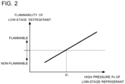
- Fig. 2 is a graph illustrating the relationship between flammability and the pressure P of the low-stage refrigerant.
- Fig. 2 is a graph when the low-stage refrigerant is a zeotropic refrigerant mixture in which refrigerant having a higher-boiling-point is flammable as described in the present embodiment. As illustrated in Fig.
- the pressure P of the low-stage refrigerant needs to be equal to or lower than a threshold P T to maintain the low-stage refrigerant to be non-flammable.
- the threshold P T is uniquely determined by physical properties of refrigerants that constitute the low-stage refrigerant.
- the threshold P T is set in advance appropriate to the low-stage refrigerant and stored in the controller 3.
- the controller 3 controls the capacity of the high-stage circuit 1 such that the pressure P of the low-stage refrigerant detected by the pressure sensor 26 is equal to or lower than the threshold P T .
- Fig. 3 is a flowchart illustrating operation of the refrigeration cycle apparatus 100 according to Embodiment 1.
- the controller 3 drives the first compressor 11 and the second compressor 21 (S1). This causes the high-stage refrigerant to circulate in the high-stage circuit 1, and causes the low-stage refrigerant to circulate in the low-stage circuit 2, so that the freezer compartment is cooled.
- the controller 3 determines whether to stop operation of the refrigeration cycle apparatus 100 based on an instruction from a user or other information (S2). When the controller 3 does not stop operation of the refrigeration cycle apparatus 100 (S2: NO), the controller 3 continues operation of the high-stage circuit 1 and the low-stage circuit 2 until receiving an instruction to stop operation of the refrigeration cycle apparatus 100.
- the controller 3 stops operation of the refrigeration cycle apparatus 100 (S2: YES)
- the controller 3 deactivates the second compressor 21 (S3). This causes the low-stage refrigerant to stop circulating in the low-stage circuit 2. Note that at this time, operation of the first compressor 11 is continued.
- the pressure sensor 26 detects the pressure P of the low-stage refrigerant (S4).
- the controller 3 determines whether the pressure P of the low-stage refrigerant detected by the pressure sensor 26 is equal to or lower than the threshold P T (S5).
- the controller 3 shifts to step S7, while maintaining the capacity of the high-stage circuit 1.
- the controller 3 increases the capacity of the high-stage circuit 1 (S6).
- the controller 3 may increase the operating frequency of the first compressor 11 by a predetermined constant value, or may increase it by a value corresponding to a difference between the pressure P of the low-stage refrigerant and the threshold P T .
- the temperature of the high-stage refrigerant flowing through the high-stage flow passage 141 in the cascade heat exchanger 14 is decreased. With this decrease, the temperature of the low-stage refrigerant that exchanges heat with the high-stage refrigerant through the cascade heat exchanger 14 is decreased, and accordingly the pressure P of the low-stage refrigerant is decreased. As the pressure P of the low-stage refrigerant is decreased, the density of the gas in the low-stage circuit 2 is decreased, and accordingly the mass of the gas refrigerant in the low-stage circuit 2 is reduced.
- the controller 3 determines whether to start operation of the refrigeration cycle apparatus 100 based on an instruction from a user or other information (S7). When the controller 3 does not start operation of the refrigeration cycle apparatus 100 (S7: NO), the controller 3 returns to step S4 to repeat the subsequent processes. When the controller 3 starts operation of the refrigeration cycle apparatus 100 (S7: YES), the controller 3 shifts to step S1 to drive the second compressor 21 to cause the low-stage refrigerant to circulate in the low-stage circuit 2.
- operation of the high-stage circuit 1 is continued even after stopping operation of the low-stage circuit 2, and the high-stage circuit 1 is controlled such that the pressure P of the low-stage refrigerant is equal to or lower than the threshold P T at or below which the low-stage refrigerant is non-flammable.
- This can reduce variations in the composition of the low-stage refrigerant in the low-stage circuit 2 after stopping operation of the low-stage circuit 2.
- a zeotropic refrigerant mixture containing a flammable refrigerant is used as the low-stage refrigerant, it is still possible to suppress the increase in risk due to the flammability at the time of refrigerant leakage.
- the freezing point of CO 2 can be decreased. This makes it possible to achieve cooling even at the freezing point (-56 degrees C) or lower.
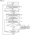
- Fig. 4 is a flowchart illustrating operation of the refrigeration cycle apparatus 100 according to Embodiment 2.
- the refrigeration cycle apparatus 100 operates differently from the operation in Embodiment 1.
- the configuration of the refrigeration cycle apparatus 100 is the same as that in Embodiment 1.
- the controller 3 when receiving an instruction from a user or other information to start operation of the refrigeration cycle apparatus 100, the controller 3 drives the first compressor 11 and the second compressor 21 (S11). This causes the high-stage refrigerant to circulate in the high-stage circuit 1, and causes the low-stage refrigerant to circulate in the low-stage circuit 2.
- the controller 3 determines whether to stop operation of the refrigeration cycle apparatus 100 based on an instruction or the like from a user (S12). When the controller 3 does not stop operation of the refrigeration cycle apparatus 100 (S12: NO), the controller 3 continues operation of the high-stage circuit 1 and the low-stage circuit 2 until receiving an instruction to stop operation of the refrigeration cycle apparatus 100.
- the controller 3 performs pump-down operation of the low-stage circuit 2 (S13). Specifically, the controller 3 fully closes the second expansion device 23, while continuing operation of the second compressor 21. Since the second expansion device 23 is closed, the low-stage refrigerant in the low-stage circuit 2 is collected on a high-pressure side of the low-stage circuit 2.
- the high-pressure side of the low-stage circuit 2 is between a discharge port of the second compressor 21 and a refrigerant inlet of the second expansion device 23. This generates a negative pressure (equal to or lower than the atmospheric pressure) on a low-pressure side of the low-stage circuit 2.
- the low-pressure side of the low-stage circuit 2 is between a refrigerant outlet of the second expansion device 23 and a suction port of the second compressor 21.
- the controller 3 deactivates the second compressor 21 (S14). This causes the low-stage refrigerant to stop circulating in the low-stage circuit 2.
- a solenoid valve may be provided between the low-stage flow passage 142 in the cascade heat exchanger 14 and the second expansion device 23 to perform the pump-down operation by closing the solenoid valve.
- a pressure sensor configured to detect a low pressure of the low-stage refrigerant may be provided on the low-pressure side of the low-stage circuit 2, that is, between the refrigerant outlet of the second expansion device 23 and the suction port of the second compressor 21.
- the controller 3 may deactivate the second compressor 21. This can prevent a fault or other problems caused by continuously driving the second compressor 21 even after there is no refrigerant left on the low-pressure side of the low-stage circuit 2.
- the subsequent processes in steps S15 to S18 are the same as those in steps S4 to S7 in Embodiment 1.
- the high-stage circuit 1 is controlled such that the pressure P of the low-stage refrigerant is equal to or lower than the threshold P T .
- the pressure sensor 26 is configured to detect the pressure P of the low-stage refrigerant collected on the high-pressure side of the low-stage circuit 2. That is, the pressure sensor 26 is provided between the discharge port of the second compressor 21 and the refrigerant inlet of the second expansion device 23.
- the refrigeration cycle apparatus 100 in the present embodiment performs pump-down operation after stopping operation of the low-stage circuit 2, and can thereby generate a negative pressure on the low-pressure side of the low-stage circuit 2. This can prevent gas refrigerant from leaking from the welding portion provided on the low-pressure side of the low-stage circuit 2. As a result, it is possible to further reduce variations in the composition of the liquid refrigerant in the low-stage circuit 2 during a stop of operation of the refrigeration cycle apparatus 100.
- the low-stage refrigerant is not limited to the zeotropic refrigerant mixture of CO 2 and R290, but may be other zeotropic refrigerant mixtures.
- the low-stage refrigerant is the zeotropic refrigerant mixture containing CO 2 and a flammable refrigerant, the effects achieved by the above embodiments can be particularly obtained.
- the refrigeration cycle apparatus 100 has the configuration in which the controller 3 controls the refrigeration cycle apparatus 100 in its entirety.
- the controller 3 may be provided in each of the high-stage circuit 1 and the low-stage circuit 2, such that the controllers 3 individually control operation of the high-stage circuit 1 and operation of the low-stage circuit 2.
- the refrigeration cycle apparatus 100 has the configuration in which the controller 3 controls the operating frequency of the first compressor 11 to thereby control the capacity of the high-stage circuit 1.
- the refrigeration cycle apparatus 100 is not limited to having this configuration.
- the controller 3 may control the opening degree of the first expansion device 13 in the high-stage circuit 1 or the rotation speed of the first fan 15 to thereby control the capacity of the high-stage circuit 1.
- the controller 3 increases the opening degree of the first expansion device 13 or the rotation speed of the first fan 15 to thereby increase the capacity of the high-stage circuit 1.
- the low-stage circuit 2 in the refrigeration cycle apparatus 100 may include a receiver 22.
- Fig. 5 is a schematic configuration diagram of a refrigeration cycle apparatus 100A according to Modification 1. As illustrated in Fig. 5 , the low-stage circuit 2 in the refrigeration cycle apparatus 100A includes the receiver 22 between the cascade heat exchanger 14 and the second expansion device 23. The receiver 22 is configured to temporarily accumulate therein the low-stage refrigerant flowing out from the low-stage flow passage 142 in the cascade heat exchanger 14. Surplus refrigerant generated due to variations in cooling load is accumulated in the receiver 22.
- the refrigeration cycle apparatus 100A includes the receiver 22, operation of the high-stage circuit 1 is continued after stopping operation of the low-stage circuit 2, and the high-stage circuit 1 is controlled such that the pressure P of the low-stage refrigerant is equal to or lower than the threshold P T at or below which the low-stage refrigerant is non-flammable.
- the high-stage circuit 1 may be controlled such that a high pressure of the low-stage refrigerant is equal to or lower than the threshold P T at or below which the low-stage refrigerant is non-flammable, even during operation of the low-stage circuit 2.
- the refrigeration cycle apparatus 100 has the configuration in which the controller 3 controls the high-stage circuit 1 based on the pressure P of the low-stage refrigerant detected by the pressure sensor 26 after stopping operation of the low-stage circuit 2.
- the refrigeration cycle apparatus 100 is not limited to having this configuration.
- the controller 3 may control the high-stage circuit 1 based on the temperature of a low-stage refrigerant associated with the pressure P of the low-stage refrigerant.
- the low-stage circuit 2 may be provided with a pressure relief device configured to be opened when the pressure or temperature increases to a reference value, and the pressure relief device may be used to maintain the pressure P of the low-stage refrigerant in the low-stage circuit 2 to be equal to or lower than a pressure value at or below which the low-stage refrigerant is non-flammable.
- Fig. 6 is a schematic configuration diagram of a refrigeration cycle apparatus 100B according to Modification 2.
- the refrigeration cycle apparatus 100B includes a pressure relief device 27.
- the pressure relief device 27 is provided at any location in the low-stage circuit 2. Note that in a case where the pump-down operation is performed as described in Embodiment 2, the pressure relief device 27 is provided on the high-pressure side of the low-stage circuit 2.
- the pressure relief device 27 is a pressure relief valve or a fusible plug.
- the threshold P T refers to a pressure value or a temperature at or below which the low-stage refrigerant is non-flammable, similarly to the above embodiments. This helps maintain the pressure P of the low-stage refrigerant to be equal to or lower than the pressure value at or below which the low-stage refrigerant is non-flammable even after stopping operation of the low-stage circuit 2. Note that in the present modification, after stopping operation of the low-stage circuit 2, operation of the high-stage circuit 1 may be stopped. Alternatively, even after stopping operation of the low-stage circuit 2, the high-stage circuit 1 may still be continuously operated, and a pressure control using the pressure relief device 27 may be executed in combination with a control of the high-stage circuit 1 based on the pressure P of the low-stage refrigerant.
- 1 high-stage circuit
- 2 low-stage circuit
- 3 controller
- 11 first compressor
- 12 condenser
- 13 first expansion device
- 14 cascade heat exchanger
- 15 first fan
- 21 second compressor
- 22 receiver
- 23 second expansion device
- 24 evaporator
- 25 second fan
- 26 pressure sensor
- 27 pressure relief device
- 100, 100A, 100B refrigeration cycle apparatus
- 141 high-stage flow passage
- 142 low-stage flow passage
Landscapes
- Engineering & Computer Science (AREA)
- Physics & Mathematics (AREA)
- Mechanical Engineering (AREA)
- Thermal Sciences (AREA)
- General Engineering & Computer Science (AREA)
- Chemical & Material Sciences (AREA)
- Analytical Chemistry (AREA)
- Power Engineering (AREA)
- Compression-Type Refrigeration Machines With Reversible Cycles (AREA)
- Devices That Are Associated With Refrigeration Equipment (AREA)
Abstract
Description
- The present disclosure relates to a refrigeration cycle apparatus provided with a two-stage refrigeration cycle, and also relates to a method for controlling the refrigeration cycle apparatus.
- As a conventional refrigeration cycle apparatus provided with a two-stage refrigeration cycle, a refrigeration apparatus including a low-stage circuit through which a low-stage refrigerant circulates, a high-stage circuit through which a high-stage refrigerant circulates, and a cascade condenser configured to exchange heat between the low-stage refrigerant and the high-stage refrigerant has been known (for example, Patent Literature 1).
- Patent Literature 1: International Publication No.
WO 2014030236 - In the refrigeration cycle apparatus disclosed in Patent Literature 1, a zeotropic refrigerant mixture is used as a low-stage refrigerant that circulates in the low-stage circuit. In this case, during a stop of operation of the low-stage circuit, refrigerant having a low-boiling-point contained in the zeotropic refrigerant mixture is gasified and remains in the low-stage circuit in its entirety, which may vary the composition of liquid refrigerant. Particularly, in a case where the low-stage circuit includes a welding portion of pipes, if the gasified refrigerant leaks from the welding portion, the leakage leads to significant variations in the composition of the liquid refrigerant. When refrigerant having a high-boiling-point contained in the zeotropic refrigerant mixture is flammable, the variations in the composition of the refrigerant lead to an increase in flammability of the liquid refrigerant, and accordingly an increase in the risk due to the flammability at the time of refrigerant leakage.
- The present disclosure has been made to solve the above problems, and it is an object of the present disclosure to provide a refrigeration cycle apparatus and a method for controlling the refrigeration cycle apparatus that can reduce variations in composition of refrigerant after stopping operation of a low-stage circuit.
- A refrigeration cycle apparatus according to one embodiment of the present disclosure includes: a high-stage circuit through which a high-stage refrigerant circulates, the high-stage circuit including a first compressor, a condenser, a first expansion device, and a cascade heat exchanger; and a low-stage circuit through which a low-stage refrigerant circulates, the low-stage circuit including a second compressor, the cascade heat exchanger, a second expansion device, and an evaporator, wherein the cascade heat exchanger is configured to exchange heat between the high-stage refrigerant and the low-stage refrigerant, the low-stage refrigerant is a zeotropic refrigerant mixture, and pressure of the low-stage refrigerant in the low-stage circuit after deactivating the second compressor is maintained to be equal to or lower than a pressure at or below which the low-stage refrigerant is non-flammable.
- A method for controlling a refrigeration cycle apparatus according to another embodiment of the present disclosure is a method for controlling a refrigeration cycle apparatus, the refrigeration cycle apparatus including a high-stage circuit through which a high-stage refrigerant circulates and a low-stage circuit through which a low-stage refrigerant circulates, the high-stage circuit including a first compressor, a condenser, a first expansion device, and a cascade heat exchanger, the low-stage circuit including a second compressor, the cascade heat exchanger, a second expansion device, and an evaporator, the cascade heat exchanger being configured to exchange heat between the high-stage refrigerant and the low-stage refrigerant, the low-stage refrigerant being a zeotropic refrigerant mixture, the method including maintaining pressure of the low-stage refrigerant in the low-stage circuit after deactivating the second compressor to be equal to or lower than a pressure at or below which the low-stage refrigerant is non-flammable.
- According to the embodiments of the present disclosure, the pressure of the low-stage refrigerant in the low-stage circuit after deactivating the second compressor is maintained to be equal to or lower than a pressure at or below which the low-stage refrigerant is non-flammable, so that it is possible to reduce variations in composition of the refrigerant after stopping operation of the low-stage circuit.
-
- [
Fig. 1] Fig. 1 is a schematic configuration diagram of a refrigeration cycle apparatus according to Embodiment 1. - [
Fig. 2] Fig. 2 is a graph illustrating a relationship between flammability and a pressure P of a low-stage refrigerant. - [
Fig. 3] Fig. 3 is a flowchart illustrating operation of the refrigeration cycle apparatus according to Embodiment 1. - [
Fig. 4] Fig. 4 is a flowchart illustrating operation of the refrigeration cycle apparatus according toEmbodiment 2. - [
Fig. 5] Fig. 5 is a schematic configuration diagram of a refrigeration cycle apparatus according to Modification 1. - [
Fig. 6] Fig. 6 is a schematic configuration diagram of a refrigeration cycle apparatus according toModification 2. - Hereinafter, embodiments will be described based on the drawings. Note that in the drawings below, the same reference signs denote the same or equivalent components. In addition, the relationship of sizes of the components in the drawings described below may differ from that of actual ones. Furthermore, the level of temperature, pressure, and other factors in the descriptions below is not particularly determined in relation to an absolute value, but is determined relative to the conditions, operation, or other factors of the system, device, or the like.
- A
refrigeration cycle apparatus 100 according to Embodiment 1 is described below. Therefrigeration cycle apparatus 100 is provided with a two-stage refrigeration cycle in which refrigerant circulates independently in each refrigerant cycle. Therefrigeration cycle apparatus 100 is used for various purposes such as freezing, refrigeration, hot-water supply, or air-conditioning. In the present embodiment, an example is described in which therefrigeration cycle apparatus 100 is used as a refrigeration apparatus configured to cool a freezer compartment or the like. -
Fig. 1 is a schematic configuration diagram of therefrigeration cycle apparatus 100 according to Embodiment 1. As illustrated inFig. 1 , therefrigeration cycle apparatus 100 in the present embodiment includes a high-stage circuit 1, a low-stage circuit 2, and acontroller 3. The high-stage circuit 1 is a high-temperature circuit through which a high-stage refrigerant circulates. The low-stage circuit 2 is a lowtemperature circuit through which a low-stage refrigerant circulates. The low-stage refrigerant has a boiling point lower than that of the high-stage refrigerant. The high-stage circuit 1 and the low-stage circuit 2 include acascade heat exchanger 14 that is shared between them. Through thecascade heat exchanger 14, the high-stage refrigerant circulating in the high-stage circuit 1 exchanges heat with the low-stage refrigerant circulating in the low-stage circuit 2. - The high-stage circuit 1 includes a
first compressor 11, acondenser 12, afirst expansion device 13, and thecascade heat exchanger 14. Thefirst compressor 11, thecondenser 12, thefirst expansion device 13, and thecascade heat exchanger 14 are connected in this order by pipes. Examples of the high-stage refrigerant circulating in the high-stage circuit 1 include an HFC-based single refrigerant such as R134a, R32, or R410A, a refrigerant mixture thereof, an HFO-based single refrigerant such as HFO-1234yf, and a refrigerant mixture thereof. - The
first compressor 11 is, for example, an inverter-type compressor whose capacity is controllable. Thefirst compressor 11 suctions a high-stage refrigerant, compresses the suctioned high-stage refrigerant into a high-temperature high-pressure state, and discharges the compressed high-stage refrigerant to be circulated in the high-stage circuit 1. - The
condenser 12 is, for example, a fin-and-tube heat exchanger. Thecondenser 12 is configured to exchange heat between air and a high-stage refrigerant, and condense and liquefy the high-stage refrigerant. Therefrigeration cycle apparatus 100 includes afirst fan 15 for supplying air to thecondenser 12. Examples of thefirst fan 15 include a propeller fan and a cross flow fan whose airflow volume is controllable. Note that thecondenser 12 may be, for example, a plate heat exchanger configured to exchange heat between water or brine and the high-stage refrigerant. In this case, thefirst fan 15 may be omitted. - The
first expansion device 13 is, for example, an electronic expansion valve whose opening degree is controllable. Thefirst expansion device 13 is connected to thecondenser 12 to reduce a pressure of the high-stage refrigerant flowing out from thecondenser 12 and expand the high-stage refrigerant. Note that thefirst expansion device 13 may be a capillary tube or a thermostatic expansion valve. - The
cascade heat exchanger 14 is, for example, a plate heat exchanger. Thecascade heat exchanger 14 includes a high-stage flow passage 141 connected to the high-stage circuit 1, and a low-stage flow passage 142 connected to the low-stage circuit 2. Thecascade heat exchanger 14 is configured to exchange heat between the high-stage refrigerant flowing through the high-stage flow passage 141 and the low-stage refrigerant flowing through the low-stage flow passage 142. The high-stage flow passage 141 in thecascade heat exchanger 14 serves as an evaporator to evaporate and gasify the high-stage refrigerant. The low-stage flow passage 142 in thecascade heat exchanger 14 serves as a condenser to condense and liquefy the low-stage refrigerant. - The low-
stage circuit 2 includes asecond compressor 21, thecascade heat exchanger 14, asecond expansion device 23, and anevaporator 24. Thesecond compressor 21, thecascade heat exchanger 14, thesecond expansion device 23, and theevaporator 24 are connected in this order by pipes. The low-stage refrigerant circulating in the low-stage circuit 2 is a zeotropic refrigerant mixture having a boiling point lower than that of the high-stage refrigerant. A lower evaporating temperature can be obtained by using the zeotropic refrigerant mixture, compared to the evaporating temperature obtained by using a single refrigerant. In the present embodiment, a zeotropic refrigerant mixture containing CO2 and R290 (propane) is used as the low-stage refrigerant. CO2 is refrigerant having a low-boiling-point, while R290 is refrigerant having a high-boiling-point whose boiling point is higher than that of CO2. It is possible to decrease an environmental load by using natural refrigerants such as CO2 and R290. Mixing CO2 into the low-stage refrigerant leads to an improvement in the cooling capacity, while mixing R290 into the low-stage refrigerant leads to an improvement in COP and to a decrease in triple point of CO2, which allows applications in low temperature. - The
second compressor 21 is, for example, an inverter-type compressor whose capacity is controllable. Thesecond compressor 21 suctions the low-stage refrigerant, compresses the suctioned low-stage refrigerant into a high-temperature high-pressure state, and discharges the compressed low-stage refrigerant to be circulated in the low-stage circuit 2. - The
second expansion device 23 is, for example, an electronic expansion valve whose opening degree is controllable. Thesecond expansion device 23 is connected to the low-stage flow passage 142 in thecascade heat exchanger 14 to reduce the pressure of the low-stage refrigerant flowing out from the low-stage flow passage 142 and expand the low-stage refrigerant. Note that thesecond expansion device 23 may be a capillary tube or a thermostatic expansion valve. - The
evaporator 24 is, for example, a fin-and-tube heat exchanger. Theevaporator 24 is configured to exchange heat between air and the low-stage refrigerant, and evaporate and gasify the low-stage refrigerant. Therefrigeration cycle apparatus 100 includes asecond fan 25 configured to supply air to theevaporator 24. Examples of thesecond fan 25 include a propeller fan and a cross flow fan whose airflow volume is controllable. Note that theevaporator 24 may be, for example, a plate heat exchanger configured to exchange heat between water or brine and the low-stage refrigerant. In this case, thesecond fan 25 may be omitted. - The
refrigeration cycle apparatus 100 includes apressure sensor 26 configured to detect a pressure P of the low-stage refrigerant in the low-stage circuit 2 during a stop of operation of the low-stage circuit 2. Since the pressure P of the low-stage refrigerant during a stop of operation of the low-stage circuit 2 is substantially uniform in the low-stage circuit 2, thepressure sensor 26 is provided at any location in the low-stage circuit 2. In the example illustrated inFig. 1 , thepressure sensor 26 is provided on a pipe connecting the low-stage flow passage 142 in thecascade heat exchanger 14 and thesecond expansion device 23. The pressure P of the low-stage refrigerant detected by thepressure sensor 26 is transmitted to thecontroller 3. - Note that in place of the
pressure sensor 26, therefrigeration cycle apparatus 100 may include a sensor configured to detect any other physical quantity (for example, condensing temperature) that is convertible to the pressure P of the low-stage refrigerant, such that thecontroller 3 converts the detected physical quantity to the pressure P. Therefrigeration cycle apparatus 100 may further include various types of sensors (not illustrated) such as an outside-air temperature sensor configured to detect an outside-air temperature, a room temperature sensor configured to detect a temperature in the freezer compartment, or a sensor configured to detect a refrigerant temperature or pressure at any location in the high-stage circuit 1 and the low-stage circuit 2. - The
controller 3 controls operation of therefrigeration cycle apparatus 100 in its entirety. Thecontroller 3 is constituted by a processing device including a memory configured to store data and programs necessary for controlling the operation, and a CPU configured to execute the programs, or is constituted by dedicated hardware such as ASIC or FPGA or by both the processing device and the dedicated hardware. Thecontroller 3 in the present embodiment controls the high-stage circuit 1 based on the pressure P of the low-stage refrigerant detected by thepressure sensor 26 when operation of the low-stage circuit 2 is stopped. Thecontroller 3 controls the respective devices in the high-stage circuit 1 and the low-stage circuit 2 as well as thefirst fan 15 and thesecond fan 25 based on the information received from the various types of sensors and an operating instruction given by a user. - Operation of the
refrigeration cycle apparatus 100 in the present embodiment is described below based on a flow of refrigerant circulating in each refrigerant circuit. First, operation of the high-stage circuit 1 is described. Thefirst compressor 11 and thesecond compressor 21 are driven upon receiving an instruction to start operation of therefrigeration cycle apparatus 100. Thefirst compressor 11 in the high-stage circuit 1 suctions the high-stage refrigerant, compresses the suctioned high-stage refrigerant into a high-temperature high-pressure state, and discharges the compressed high-stage refrigerant. The high-stage refrigerant discharged from thefirst compressor 11 flows into thecondenser 12. Thecondenser 12 is configured to exchange heat between air supplied by thefirst fan 15 and the high-stage refrigerant, and condenses and liquefies the high-stage refrigerant. - The high-stage refrigerant condensed and liquefied through the
condenser 12 passes through thefirst expansion device 13. Thefirst expansion device 13 reduces the pressure of the condensed and liquefied high-stage refrigerant. The high-stage refrigerant with its pressure reduced by thefirst expansion device 13 flows into the high-stage flow passage 141 in thecascade heat exchanger 14. The high-stage refrigerant flowing into the high-stage flow passage 141 exchanges heat with the low-stage refrigerant flowing through the low-stage flow passage 142 in thecascade heat exchanger 14, and is thus evaporated and gasified. The high-stage refrigerant evaporated and gasified through thecascade heat exchanger 14 is suctioned into thefirst compressor 11 again. - Next, operation of the low-
stage circuit 2 is described. Thesecond compressor 21 in the low-stage circuit 2 suctions the low-stage refrigerant, compresses the suctioned low-stage refrigerant into a high-temperature high-pressure state, and discharges the compressed low-stage refrigerant. The low-stage refrigerant discharged from thesecond compressor 21 flows into the low-stage flow passage 142 in thecascade heat exchanger 14. The low-stage refrigerant flowing into the low-stage flow passage 142 exchanges heat with the high-stage refrigerant flowing through the high-stage flow passage 141 in thecascade heat exchanger 14, and is thus condensed and liquefied. - The low-stage refrigerant condensed and liquefied through the
cascade heat exchanger 14 passes through thesecond expansion device 23. Thesecond expansion device 23 reduces the pressure of the low-stage refrigerant. The low-stage refrigerant with its pressure reduced by thesecond expansion device 23 flows into theevaporator 24. Theevaporator 24 is configured to exchange heat between air supplied by thesecond fan 25 and the low-stage refrigerant, and evaporates and gasifies the low-stage refrigerant. At this time, the low-stage refrigerant removes heat from the air, so that the freezer compartment is cooled. The low-stage refrigerant evaporated and gasified through theevaporator 24 is suctioned into thesecond compressor 21 again. - Upon receiving an instruction to stop operation of the
refrigeration cycle apparatus 100, thefirst compressor 11 and thesecond compressor 21 is deactivated, and refrigerant stops circulating in the high-stage circuit 1 and the low-stage circuit 2. At this time, the refrigerant having a low-boiling-point contained in the low-stage refrigerant in the low-stage circuit 2 in its entirety is gasified, which varies the composition of liquid refrigerant in the low-stage circuit 2. For example, as described in the present embodiment, when a zeotropic refrigerant mixture of CO2 and R290 is used as the low-stage refrigerant, CO2 having a lower boiling point than R290 is gasified, and consequently the ratio of R290 that is a flammable refrigerant increases in the liquid refrigerant. - The
evaporator 24 in the low-stage circuit 2 is located in a room such as a freezer compartment and connected to thesecond compressor 21 by an extension pipe. Due to this structure, on the suction side of thesecond compressor 21, a welding portion connected to the extension pipe is provided. If the CO2 gas leaks from the welding portion when the operation of the low-stage circuit 2 is stopped, the ratio of R290 that is a flammable refrigerant further increases in the liquid refrigerant in the low-stage circuit 2. This results in an increase in the flammability of the low-stage refrigerant in the low-stage circuit 2, and accordingly an increase in the risk due to the flammability at the time of refrigerant leakage. - In view of that, the
controller 3 in the present embodiment continues operation of the high-stage circuit 1 even after stopping the operation of the low-stage circuit 2, and controls the capacity of the high-stage circuit 1 to cause the pressure P of the low-stage refrigerant to be equal to or lower than a pressure value at or below which the low-stage refrigerant is non-flammable.Fig. 2 is a graph illustrating the relationship between flammability and the pressure P of the low-stage refrigerant.Fig. 2 is a graph when the low-stage refrigerant is a zeotropic refrigerant mixture in which refrigerant having a higher-boiling-point is flammable as described in the present embodiment. As illustrated inFig. 2 , as the pressure P of the low-stage refrigerant increases, the flammability of the low-stage refrigerant increases. In view of that, the pressure P of the low-stage refrigerant needs to be equal to or lower than a threshold PT to maintain the low-stage refrigerant to be non-flammable. The threshold PT is uniquely determined by physical properties of refrigerants that constitute the low-stage refrigerant. In the present embodiment, the threshold PT is set in advance appropriate to the low-stage refrigerant and stored in thecontroller 3. Thecontroller 3 controls the capacity of the high-stage circuit 1 such that the pressure P of the low-stage refrigerant detected by thepressure sensor 26 is equal to or lower than the threshold PT. -
Fig. 3 is a flowchart illustrating operation of therefrigeration cycle apparatus 100 according to Embodiment 1. When receiving an instruction from a user or other information to start operation of therefrigeration cycle apparatus 100, thecontroller 3 drives thefirst compressor 11 and the second compressor 21 (S1). This causes the high-stage refrigerant to circulate in the high-stage circuit 1, and causes the low-stage refrigerant to circulate in the low-stage circuit 2, so that the freezer compartment is cooled. - The
controller 3 determines whether to stop operation of therefrigeration cycle apparatus 100 based on an instruction from a user or other information (S2). When thecontroller 3 does not stop operation of the refrigeration cycle apparatus 100 (S2: NO), thecontroller 3 continues operation of the high-stage circuit 1 and the low-stage circuit 2 until receiving an instruction to stop operation of therefrigeration cycle apparatus 100. - In contrast, when the
controller 3 stops operation of the refrigeration cycle apparatus 100 (S2: YES), thecontroller 3 deactivates the second compressor 21 (S3). This causes the low-stage refrigerant to stop circulating in the low-stage circuit 2. Note that at this time, operation of thefirst compressor 11 is continued. - The
pressure sensor 26 detects the pressure P of the low-stage refrigerant (S4). Thecontroller 3 determines whether the pressure P of the low-stage refrigerant detected by thepressure sensor 26 is equal to or lower than the threshold PT (S5). When the pressure P of the low-stage refrigerant is equal to or lower than the threshold PT (S5: YES), thecontroller 3 shifts to step S7, while maintaining the capacity of the high-stage circuit 1. In contrast, when the pressure P of the low-stage refrigerant is higher than the threshold PT (S5: NO), thecontroller 3 increases the capacity of the high-stage circuit 1 (S6). Thecontroller 3 may increase the operating frequency of thefirst compressor 11 by a predetermined constant value, or may increase it by a value corresponding to a difference between the pressure P of the low-stage refrigerant and the threshold PT. - As the capacity of the high-stage circuit 1 is increased, the temperature of the high-stage refrigerant flowing through the high-
stage flow passage 141 in thecascade heat exchanger 14 is decreased. With this decrease, the temperature of the low-stage refrigerant that exchanges heat with the high-stage refrigerant through thecascade heat exchanger 14 is decreased, and accordingly the pressure P of the low-stage refrigerant is decreased. As the pressure P of the low-stage refrigerant is decreased, the density of the gas in the low-stage circuit 2 is decreased, and accordingly the mass of the gas refrigerant in the low-stage circuit 2 is reduced. That is, as the pressure P of the low-stage refrigerant is decreased, a gas amount of the refrigerant (CO2) having the low-boiling-point in the low-stage circuit 2 in its entirety after stopping operation of the low-stage circuit 2 is reduced. This can minimize variations in the composition of the liquid refrigerant in the low-stage circuit 2. - The
controller 3 determines whether to start operation of therefrigeration cycle apparatus 100 based on an instruction from a user or other information (S7). When thecontroller 3 does not start operation of the refrigeration cycle apparatus 100 (S7: NO), thecontroller 3 returns to step S4 to repeat the subsequent processes. When thecontroller 3 starts operation of the refrigeration cycle apparatus 100 (S7: YES), thecontroller 3 shifts to step S1 to drive thesecond compressor 21 to cause the low-stage refrigerant to circulate in the low-stage circuit 2. - As described above, in the
refrigeration cycle apparatus 100 in the present embodiment, operation of the high-stage circuit 1 is continued even after stopping operation of the low-stage circuit 2, and the high-stage circuit 1 is controlled such that the pressure P of the low-stage refrigerant is equal to or lower than the threshold PT at or below which the low-stage refrigerant is non-flammable. This can reduce variations in the composition of the low-stage refrigerant in the low-stage circuit 2 after stopping operation of the low-stage circuit 2. As a result of this, even when a zeotropic refrigerant mixture containing a flammable refrigerant is used as the low-stage refrigerant, it is still possible to suppress the increase in risk due to the flammability at the time of refrigerant leakage. When a refrigerant mixture containing CO2 is used as the low-stage refrigerant as described in the present embodiment, the freezing point of CO2 can be decreased. This makes it possible to achieve cooling even at the freezing point (-56 degrees C) or lower. - The
refrigeration cycle apparatus 100 according toEmbodiment 2 is described below.Fig. 4 is a flowchart illustrating operation of therefrigeration cycle apparatus 100 according toEmbodiment 2. In the present embodiment, therefrigeration cycle apparatus 100 operates differently from the operation in Embodiment 1. The configuration of therefrigeration cycle apparatus 100 is the same as that in Embodiment 1. - As illustrated in
Fig. 4 , when receiving an instruction from a user or other information to start operation of therefrigeration cycle apparatus 100, thecontroller 3 drives thefirst compressor 11 and the second compressor 21 (S11). This causes the high-stage refrigerant to circulate in the high-stage circuit 1, and causes the low-stage refrigerant to circulate in the low-stage circuit 2. - The
controller 3 determines whether to stop operation of therefrigeration cycle apparatus 100 based on an instruction or the like from a user (S12). When thecontroller 3 does not stop operation of the refrigeration cycle apparatus 100 (S12: NO), thecontroller 3 continues operation of the high-stage circuit 1 and the low-stage circuit 2 until receiving an instruction to stop operation of therefrigeration cycle apparatus 100. - In contrast, when the
controller 3 stops operation of the refrigeration cycle apparatus 100 (S12: YES), thecontroller 3 performs pump-down operation of the low-stage circuit 2 (S13). Specifically, thecontroller 3 fully closes thesecond expansion device 23, while continuing operation of thesecond compressor 21. Since thesecond expansion device 23 is closed, the low-stage refrigerant in the low-stage circuit 2 is collected on a high-pressure side of the low-stage circuit 2. The high-pressure side of the low-stage circuit 2 is between a discharge port of thesecond compressor 21 and a refrigerant inlet of thesecond expansion device 23. This generates a negative pressure (equal to or lower than the atmospheric pressure) on a low-pressure side of the low-stage circuit 2. The low-pressure side of the low-stage circuit 2 is between a refrigerant outlet of thesecond expansion device 23 and a suction port of thesecond compressor 21. - Thereafter, the
controller 3 deactivates the second compressor 21 (S14). This causes the low-stage refrigerant to stop circulating in the low-stage circuit 2. Note that a solenoid valve may be provided between the low-stage flow passage 142 in thecascade heat exchanger 14 and thesecond expansion device 23 to perform the pump-down operation by closing the solenoid valve. A pressure sensor configured to detect a low pressure of the low-stage refrigerant may be provided on the low-pressure side of the low-stage circuit 2, that is, between the refrigerant outlet of thesecond expansion device 23 and the suction port of thesecond compressor 21. When the low pressure of the low-stage refrigerant is equal to or lower than the atmospheric pressure, thecontroller 3 may deactivate thesecond compressor 21. This can prevent a fault or other problems caused by continuously driving thesecond compressor 21 even after there is no refrigerant left on the low-pressure side of the low-stage circuit 2. - The subsequent processes in steps S15 to S18 are the same as those in steps S4 to S7 in Embodiment 1. The high-stage circuit 1 is controlled such that the pressure P of the low-stage refrigerant is equal to or lower than the threshold PT. However, in the present embodiment, the
pressure sensor 26 is configured to detect the pressure P of the low-stage refrigerant collected on the high-pressure side of the low-stage circuit 2. That is, thepressure sensor 26 is provided between the discharge port of thesecond compressor 21 and the refrigerant inlet of thesecond expansion device 23. - The
refrigeration cycle apparatus 100 in the present embodiment performs pump-down operation after stopping operation of the low-stage circuit 2, and can thereby generate a negative pressure on the low-pressure side of the low-stage circuit 2. This can prevent gas refrigerant from leaking from the welding portion provided on the low-pressure side of the low-stage circuit 2. As a result, it is possible to further reduce variations in the composition of the liquid refrigerant in the low-stage circuit 2 during a stop of operation of therefrigeration cycle apparatus 100. - While the embodiments have been described above, the present disclosure is not limited to the embodiments described above, and can be variously modified or combined without departing from the scope of the present disclosure. For example, the low-stage refrigerant is not limited to the zeotropic refrigerant mixture of CO2 and R290, but may be other zeotropic refrigerant mixtures. However, when the low-stage refrigerant is the zeotropic refrigerant mixture containing CO2 and a flammable refrigerant, the effects achieved by the above embodiments can be particularly obtained.
- In the above embodiments, the
refrigeration cycle apparatus 100 has the configuration in which thecontroller 3 controls therefrigeration cycle apparatus 100 in its entirety. However, thecontroller 3 may be provided in each of the high-stage circuit 1 and the low-stage circuit 2, such that thecontrollers 3 individually control operation of the high-stage circuit 1 and operation of the low-stage circuit 2. - In the above embodiments, the
refrigeration cycle apparatus 100 has the configuration in which thecontroller 3 controls the operating frequency of thefirst compressor 11 to thereby control the capacity of the high-stage circuit 1. However, therefrigeration cycle apparatus 100 is not limited to having this configuration. For example, instead of, or in addition to, the operating frequency of thefirst compressor 11, thecontroller 3 may control the opening degree of thefirst expansion device 13 in the high-stage circuit 1 or the rotation speed of thefirst fan 15 to thereby control the capacity of the high-stage circuit 1. In this case, when the pressure P of the low-stage refrigerant is higher than the threshold PT, thecontroller 3 increases the opening degree of thefirst expansion device 13 or the rotation speed of thefirst fan 15 to thereby increase the capacity of the high-stage circuit 1. - The low-
stage circuit 2 in therefrigeration cycle apparatus 100 may include areceiver 22.Fig. 5 is a schematic configuration diagram of arefrigeration cycle apparatus 100A according to Modification 1. As illustrated inFig. 5 , the low-stage circuit 2 in therefrigeration cycle apparatus 100A includes thereceiver 22 between thecascade heat exchanger 14 and thesecond expansion device 23. Thereceiver 22 is configured to temporarily accumulate therein the low-stage refrigerant flowing out from the low-stage flow passage 142 in thecascade heat exchanger 14. Surplus refrigerant generated due to variations in cooling load is accumulated in thereceiver 22. - Even when the
refrigeration cycle apparatus 100A includes thereceiver 22, operation of the high-stage circuit 1 is continued after stopping operation of the low-stage circuit 2, and the high-stage circuit 1 is controlled such that the pressure P of the low-stage refrigerant is equal to or lower than the threshold PT at or below which the low-stage refrigerant is non-flammable. When therefrigeration cycle apparatus 100A includes thereceiver 22, the high-stage circuit 1 may be controlled such that a high pressure of the low-stage refrigerant is equal to or lower than the threshold PT at or below which the low-stage refrigerant is non-flammable, even during operation of the low-stage circuit 2. - In the above embodiments, the
refrigeration cycle apparatus 100 has the configuration in which thecontroller 3 controls the high-stage circuit 1 based on the pressure P of the low-stage refrigerant detected by thepressure sensor 26 after stopping operation of the low-stage circuit 2. However, therefrigeration cycle apparatus 100 is not limited to having this configuration. For example, thecontroller 3 may control the high-stage circuit 1 based on the temperature of a low-stage refrigerant associated with the pressure P of the low-stage refrigerant. Alternatively, the low-stage circuit 2 may be provided with a pressure relief device configured to be opened when the pressure or temperature increases to a reference value, and the pressure relief device may be used to maintain the pressure P of the low-stage refrigerant in the low-stage circuit 2 to be equal to or lower than a pressure value at or below which the low-stage refrigerant is non-flammable. -
Fig. 6 is a schematic configuration diagram of arefrigeration cycle apparatus 100B according toModification 2. As illustrated inFig. 6 , therefrigeration cycle apparatus 100B includes apressure relief device 27. Thepressure relief device 27 is provided at any location in the low-stage circuit 2. Note that in a case where the pump-down operation is performed as described inEmbodiment 2, thepressure relief device 27 is provided on the high-pressure side of the low-stage circuit 2. Thepressure relief device 27 is a pressure relief valve or a fusible plug. When the pressure P or temperature of the low-stage refrigerant is equal to or higher than the threshold PT, the valve or the plug is opened, so that gas refrigerant is discharged to the outside, and consequently the pressure P of the low-stage refrigerant decreases. The threshold PT refers to a pressure value or a temperature at or below which the low-stage refrigerant is non-flammable, similarly to the above embodiments. This helps maintain the pressure P of the low-stage refrigerant to be equal to or lower than the pressure value at or below which the low-stage refrigerant is non-flammable even after stopping operation of the low-stage circuit 2. Note that in the present modification, after stopping operation of the low-stage circuit 2, operation of the high-stage circuit 1 may be stopped. Alternatively, even after stopping operation of the low-stage circuit 2, the high-stage circuit 1 may still be continuously operated, and a pressure control using thepressure relief device 27 may be executed in combination with a control of the high-stage circuit 1 based on the pressure P of the low-stage refrigerant. - 1: high-stage circuit, 2: low-stage circuit, 3: controller, 11: first compressor, 12: condenser, 13: first expansion device, 14: cascade heat exchanger, 15: first fan, 21: second compressor, 22: receiver, 23: second expansion device, 24: evaporator, 25: second fan, 26: pressure sensor, 27: pressure relief device, 100, 100A, 100B: refrigeration cycle apparatus, 141: high-stage flow passage, 142: low-stage flow passage
Claims (8)
- A refrigeration cycle apparatus comprising:a high-stage circuit through which a high-stage refrigerant circulates, the high-stage circuit including a first compressor, a condenser, a first expansion device, and a cascade heat exchanger; anda low-stage circuit through which a low-stage refrigerant circulates, the low-stage circuit including a second compressor, the cascade heat exchanger, a second expansion device, and an evaporator, whereinthe cascade heat exchanger is configured to exchange heat between the high-stage refrigerant and the low-stage refrigerant,the low-stage refrigerant is a zeotropic refrigerant mixture, andpressure of the low-stage refrigerant in the low-stage circuit after deactivating the second compressor is maintained to be equal to or lower than a pressure at or below which the low-stage refrigerant is non-flammable.
- The refrigeration cycle apparatus of claim 1, further comprising a controller, whereinthe controller is configured to control the high-stage circuit such that pressure of the low-stage refrigerant in the low-stage circuit after deactivating the second compressor is equal to or lower than a threshold, andthe threshold is a pressure at or below which the low-stage refrigerant is non-flammable.
- The refrigeration cycle apparatus of claim 2, wherein the controller increases a capacity of the high-stage circuit when the pressure of the low-stage refrigerant is higher than the threshold.
- The refrigeration cycle apparatus of claim 2 or 3, wherein the controller increases an operating frequency of the first compressor when the pressure of the low-stage refrigerant is higher than the threshold.
- The refrigeration cycle apparatus of any one of claims 2 to 4, wherein the controller performs pump-down operation of the low-stage circuit before deactivating the second compressor.
- The refrigeration cycle apparatus of claim 1, whereinthe low-stage circuit includes a pressure relief device configured to be opened when the pressure of the low-stage refrigerant in the low-stage circuit is equal to or higher than a threshold, andthe threshold is a pressure at or below which the low-stage refrigerant is non-flammable.
- The refrigeration cycle apparatus of any one of claims 1 to 6, wherein the low-stage refrigerant is a zeotropic refrigerant mixture containing CO2 and a flammable refrigerant.
- A method for controlling a refrigeration cycle apparatus,the refrigeration cycle apparatus comprising a high-stage circuit through which a high-stage refrigerant circulates and a low-stage circuit through which a low-stage refrigerant circulates,the high-stage circuit including a first compressor, a condenser, a first expansion device, and a cascade heat exchanger,the low-stage circuit including a second compressor, the cascade heat exchanger, a second expansion device, and an evaporator,the cascade heat exchanger being configured to exchange heat between the high-stage refrigerant and the low-stage refrigerant,the low-stage refrigerant being a zeotropic refrigerant mixture,the method comprisingmaintaining pressure of the low-stage refrigerant in the low-stage circuit after deactivating the second compressor to be equal to or lower than a pressure at or below which the low-stage refrigerant is non-flammable.
Applications Claiming Priority (1)
| Application Number | Priority Date | Filing Date | Title |
|---|---|---|---|
| PCT/JP2021/029053 WO2023012961A1 (en) | 2021-08-05 | 2021-08-05 | Refrigeration circuit device and control method for refrigeration circuit device |
Publications (2)
| Publication Number | Publication Date |
|---|---|
| EP4382828A1 true EP4382828A1 (en) | 2024-06-12 |
| EP4382828A4 EP4382828A4 (en) | 2024-09-25 |
Family
ID=85154434
Family Applications (1)
| Application Number | Title | Priority Date | Filing Date |
|---|---|---|---|
| EP21952786.8A Withdrawn EP4382828A4 (en) | 2021-08-05 | 2021-08-05 | Refrigeration circuit device and control method for refrigeration circuit device |
Country Status (4)
| Country | Link |
|---|---|
| EP (1) | EP4382828A4 (en) |
| JP (1) | JP7603822B2 (en) |
| CN (1) | CN117730234A (en) |
| WO (1) | WO2023012961A1 (en) |
Family Cites Families (11)
| Publication number | Priority date | Publication date | Assignee | Title |
|---|---|---|---|---|
| JP2000234811A (en) | 1999-02-17 | 2000-08-29 | Matsushita Electric Ind Co Ltd | Refrigeration cycle device |
| JP2001019944A (en) | 1999-07-09 | 2001-01-23 | Matsushita Electric Ind Co Ltd | Low-temperature working fluid and refrigeration cycle device using it |
| JP2004190917A (en) | 2002-12-10 | 2004-07-08 | Sanyo Electric Co Ltd | Refrigeration device |
| JP2008215672A (en) | 2007-03-01 | 2008-09-18 | Mac:Kk | Residual gas recovery method and apparatus for refrigeration cycle using flammable refrigerant gas |
| JP5854751B2 (en) * | 2011-10-12 | 2016-02-09 | 三菱電機株式会社 | Cooling system |
| WO2014030236A1 (en) | 2012-08-23 | 2014-02-27 | 三菱電機株式会社 | Refrigeration device |
| JP5800994B2 (en) | 2012-09-21 | 2015-10-28 | 三菱電機株式会社 | Refrigeration apparatus and control method thereof |
| JP5995990B2 (en) * | 2012-11-20 | 2016-09-21 | 三菱電機株式会社 | Refrigeration equipment |
| CN105579790B (en) * | 2013-09-27 | 2017-04-05 | 松下健康医疗控股株式会社 | Refrigerating plant |
| WO2015140873A1 (en) | 2014-03-17 | 2015-09-24 | 三菱電機株式会社 | Refrigerating device and refrigerating device control method |
| EP3617612B1 (en) | 2017-04-25 | 2021-09-01 | Mitsubishi Electric Corporation | Binary refrigeration device |
-
2021
- 2021-08-05 WO PCT/JP2021/029053 patent/WO2023012961A1/en not_active Ceased
- 2021-08-05 EP EP21952786.8A patent/EP4382828A4/en not_active Withdrawn
- 2021-08-05 JP JP2023539475A patent/JP7603822B2/en active Active
- 2021-08-05 CN CN202180101054.5A patent/CN117730234A/en active Pending
Also Published As
| Publication number | Publication date |
|---|---|
| CN117730234A (en) | 2024-03-19 |
| JP7603822B2 (en) | 2024-12-20 |
| JPWO2023012961A1 (en) | 2023-02-09 |
| WO2023012961A1 (en) | 2023-02-09 |
| EP4382828A4 (en) | 2024-09-25 |
Similar Documents
| Publication | Publication Date | Title |
|---|---|---|
| EP3683524B1 (en) | Refrigeration apparatus | |
| US12209761B2 (en) | Air-conditioning apparatus with defrost bypass circuit | |
| EP2306122B1 (en) | Refrigerating cycle apparatus, and air conditioning apparatus | |
| CN104541115B (en) | Binary Refrigeration Unit | |
| US20100281894A1 (en) | Capacity modulation of refrigerant vapor compression system | |
| US20110023512A1 (en) | Air conditioner | |
| CN111094877B (en) | Refrigeration cycle device and refrigeration device | |
| US11512880B2 (en) | Refrigeration cycle device | |
| EP2910872B1 (en) | Freezing device | |
| CN110709649B (en) | Refrigeration cycle device | |
| GB2562639A (en) | Refrigeration device | |
| JP6732862B2 (en) | Refrigeration equipment | |
| JP2010101552A (en) | Gas injection refrigeration system | |
| EP4382828A1 (en) | Refrigeration circuit device and control method for refrigeration circuit device | |
| JP6537629B2 (en) | Air conditioner | |
| EP4382827A1 (en) | Refrigeration circuit device and refrigeration circuit control method | |
| WO2016135904A1 (en) | Refrigeration apparatus | |
| JP6590945B2 (en) | Refrigeration equipment | |
| JP7058657B2 (en) | Refrigeration air conditioner and control device | |
| WO2021240615A1 (en) | Refrigeration cycle device | |
| US12571568B2 (en) | Refrigerant circuit expansion valve control | |
| JP7796887B2 (en) | Refrigeration cycle device and air conditioning device | |
| WO2020008916A1 (en) | Refrigeration cycle device and method for controlling same | |
| WO2022249289A1 (en) | Refrigeration cycle device |
Legal Events
| Date | Code | Title | Description |
|---|---|---|---|
| STAA | Information on the status of an ep patent application or granted ep patent |
Free format text: STATUS: THE INTERNATIONAL PUBLICATION HAS BEEN MADE |
|
| PUAI | Public reference made under article 153(3) epc to a published international application that has entered the european phase |
Free format text: ORIGINAL CODE: 0009012 |
|
| STAA | Information on the status of an ep patent application or granted ep patent |
Free format text: STATUS: REQUEST FOR EXAMINATION WAS MADE |
|
| 17P | Request for examination filed |
Effective date: 20240105 |
|
| AK | Designated contracting states |
Kind code of ref document: A1 Designated state(s): AL AT BE BG CH CY CZ DE DK EE ES FI FR GB GR HR HU IE IS IT LI LT LU LV MC MK MT NL NO PL PT RO RS SE SI SK SM TR |
|
| REG | Reference to a national code |
Ref country code: DE Ref legal event code: R079 Free format text: PREVIOUS MAIN CLASS: F25B0001000000 Ipc: F25B0007000000 |
|
| A4 | Supplementary search report drawn up and despatched |
Effective date: 20240822 |
|
| RIC1 | Information provided on ipc code assigned before grant |
Ipc: F25B 49/02 20060101ALI20240817BHEP Ipc: F25B 49/00 20060101ALI20240817BHEP Ipc: F25B 43/00 20060101ALI20240817BHEP Ipc: F25B 25/00 20060101ALI20240817BHEP Ipc: F25B 9/00 20060101ALI20240817BHEP Ipc: F25B 1/00 20060101ALI20240817BHEP Ipc: F25B 7/00 20060101AFI20240817BHEP |
|
| STAA | Information on the status of an ep patent application or granted ep patent |
Free format text: STATUS: THE APPLICATION HAS BEEN WITHDRAWN |
|
| DAV | Request for validation of the european patent (deleted) | ||
| DAX | Request for extension of the european patent (deleted) | ||
| 18W | Application withdrawn |
Effective date: 20241104 |