EP4382820A1 - Air guide ring, air conditioner outdoor unit, and air conditioner - Google Patents
Air guide ring, air conditioner outdoor unit, and air conditioner Download PDFInfo
- Publication number
- EP4382820A1 EP4382820A1 EP22851971.6A EP22851971A EP4382820A1 EP 4382820 A1 EP4382820 A1 EP 4382820A1 EP 22851971 A EP22851971 A EP 22851971A EP 4382820 A1 EP4382820 A1 EP 4382820A1
- Authority
- EP
- European Patent Office
- Prior art keywords
- air guide
- guide ring
- limit
- air
- sub
- Prior art date
- Legal status (The legal status is an assumption and is not a legal conclusion. Google has not performed a legal analysis and makes no representation as to the accuracy of the status listed.)
- Granted
Links
Images






Classifications
-
- F—MECHANICAL ENGINEERING; LIGHTING; HEATING; WEAPONS; BLASTING
- F24—HEATING; RANGES; VENTILATING
- F24F—AIR-CONDITIONING; AIR-HUMIDIFICATION; VENTILATION; USE OF AIR CURRENTS FOR SCREENING
- F24F1/00—Room units for air-conditioning, e.g. separate or self-contained units or units receiving primary air from a central station
- F24F1/06—Separate outdoor units, e.g. outdoor unit to be linked to a separate room comprising a compressor and a heat exchanger
- F24F1/38—Fan details of outdoor units, e.g. bell-mouth shaped inlets or fan mountings
-
- F—MECHANICAL ENGINEERING; LIGHTING; HEATING; WEAPONS; BLASTING
- F24—HEATING; RANGES; VENTILATING
- F24F—AIR-CONDITIONING; AIR-HUMIDIFICATION; VENTILATION; USE OF AIR CURRENTS FOR SCREENING
- F24F1/00—Room units for air-conditioning, e.g. separate or self-contained units or units receiving primary air from a central station
- F24F1/06—Separate outdoor units, e.g. outdoor unit to be linked to a separate room comprising a compressor and a heat exchanger
- F24F1/46—Component arrangements in separate outdoor units
- F24F1/48—Component arrangements in separate outdoor units characterised by air airflow, e.g. inlet or outlet airflow
- F24F1/50—Component arrangements in separate outdoor units characterised by air airflow, e.g. inlet or outlet airflow with outlet air in upward direction
Definitions
- the present application relates to but is not limited to the field of air conditioning devices, and in particular relates to but is not limited to an air guide ring, an air conditioner outdoor unit and an air conditioner.
- Air output amount of an air conditioner is a key index that affects performance of the air conditioner
- the air guide ring is a key component that affects the air output amount, which is mainly reflected in two aspects: a structure of the air guide ring itself and its cooperation with fan blades.
- An air guide ring is configured to be applicable to an air conditioner outdoor unit.
- the air guide ring includes an air guide ring body, in which an air guide channel is defined.
- the air guide ring body is provided with a first limit part and a second limit part.
- the first limit part and the second limit part are provided to be fitted with a fixing member of the air conditioner outdoor unit for bidirectional limiting, so as to prevent inward contracting deformation and outward expanding deformation of the air guide ring body.
- An air conditioner outdoor unit includes a fixing member and the air guide ring described above.
- the fixing member is provided with a first limit fitting part and a second limit fitting part.
- the first limit fitting part is fitted with the first limit part of the air guide ring to obstruct the outward expanding deformation of the air guide ring body.
- the second limit fitting part is fitted with the second limit part of the air guide ring to obstruct the inward contracting deformation of the air guide ring body.
- An air conditioner includes the above air conditioner outdoor unit.
- An air guide ring includes an inlet section, a middle section and an outlet section arranged in sequence along a flowing direction of airflow.
- the inlet section includes a first sub-inlet section disposed close to an air inlet end of the air guide ring and a second sub-inlet section disposed close to the middle section.
- An inner wall surface of the first sub-inlet section is a concave surface recessing toward the outside of the air guide ring
- an inner wall surface of the second sub-inlet section is a convex curved surface protruding toward the inside of the air guide ring.
- an included angle between a tangent plane of the inner wall surface of the first sub-inlet section and a first plane perpendicular to an axis of the air guide ring gradually decreases, and an included angle between a tangent plane of the inner wall surface of the second sub-inlet section and the first plane gradually increases.
- An air conditioner outdoor unit includes the above air guide ring.
- An air conditioner includes the above air conditioner outdoor unit.
- an embodiment of the present application provides an air guide ring, which can reduce a deformation amount of the air guide ring after being stressed, maintain the installation gap between the air guide ring and the fan blades, and improve performance of the air conditioner.
- an embodiment of the present application provides an air guide ring 1, which can be used for an air conditioner outdoor unit.
- the air guide ring 1 is provided to include an air guide ring body 11, and the integral air guide ring body 11 is annular.
- An air guide channel 10 is defined inside the air guide ring body 11, and the air guide channel 10 has an air inlet and an air outlet.
- the air guide ring 1 can be fitted with a fan, and fan blades of the fan can extend into the air guide channel 10 of the air guide ring 1, so that when the fan is working, airflow can enter from the air inlet, flow through the air guide channel 10, and finally be discharged from the air outlet.
- a flowing direction of the airflow is shown by the arrows in FIG. 1 , with the air inlet of the air guide channel 10 on the lower side and the air outlet of the air guide channel 10 on the upper side.
- the air guide ring body 11 is provided with two limit parts which are a first limit part 12 and a second limit part 13 respectively. Both the first limit part 12 and the second limit part 13 can be fitted with a fixing member 2 for limiting.
- the first limit part 12 can be fitted with the first limit fitting part 211 of the fixing member 2 of the air conditioner outdoor unit for limiting, so as to prevent radially outward expanding deformation of the air guide ring body 11.
- the second limit part 13 can be fitted with the second limit fitting part 212 of the fixing member 2 to prevent radially inward contracting deformation of the air guide ring body 11. That is, the two limit parts can be fitted to limit the air guide ring body 11 bidirectionally, which can limit the radially outward expanding deformation and the radially inward contracting deformation of the air guide ring body 11.
- the air guide ring body 11 is integrally annular, when a portion of the air guide ring body 11 expands and deforms radially outward, other portions of the air guide ring body 11 will contract and deform radially inward; or when a portion of the air guide ring body 11 contracts and deforms radially inward, other portions of the air guide ring body 11 will expand and deform radially outward.
- the first limit part 12 and the second limit part 13 limit the contraction and expanding deformation of the air guide ring body 11, which facilitates reducing the deformation amount of the air guide ring 1 after being stressed and maintaining shape stability of the air guide ring body 11, so as to maintain the installation gap between the air guide ring 1 and the fan blades during the operation of the air conditioner, thus avoiding mutual contact between the air guide ring 1 and the fan blades and even the damage of the fan blades caused by a too small gap and reduction in air output amount caused by a too large gap, and improving the performance of the air conditioner.
- a common air guide ring is easy to deform during installation, which affects the fitting between an air wheel and the air guide ring, causing leakage loss at the tips of air wheel blades to increase, resulting in deterioration of performance of the fan system.
- the air guide ring 1 by providing the first limit part 12 and the second limit part 13, the deformation of the air guide ring 1 is avoided, the fitting between the air wheel and the air guide ring 1 is ensured, the leakage loss at the tips of the air wheel blades is reduced, the performance of the fan system is ensured, thereby avoiding failure of the fan system.
- the second limit part 13 is disposed radially outward of the first limit part 12 (i.e., away from a center of the air guide ring body 11), and a radial interval is provided between the second limit part 13 and the first limit part 12.
- the second limit part 13 and the first limit part 12 can be clamped on two sides of the fixing member 2.
- An outside wall surface of the first limit part 12 i.e., a side wall surface on a side away from the center of the air guide ring body 11
- an inside wall surface of the second limit part 13 i.e., a side wall surface on a side close to the center of the air guide ring body 11
- the first limit surface 123 and the second limit surface 131 may be parallel to each other.
- the second limit surface 131 is located radially outward of the first limit surface 123, and a radial interval is provided between the first limit surface 123 and the second limit surface 131.
- a first limit fitting part 211 of the fixing member 2 can abut against the first limit surface 123 for limiting, and a second limit fitting part 212 of the fixing member 2 can abut against the second limit surface 131 for limiting, so as to prevent radially outward expanding deformation and radially inward contracting deformation of the air guide ring body 11 and in turn reduce the deformation amount of the air guide ring 1 after being stressed.
- the second limit part 13 and the first limit part 12 are provided to be offset along a circumferential direction of the air guide ring body 11, that is, the second limit part 13 and the first limit part 12 are located at different circumferential positions on the air guide ring body 11.
- the second limit part 13 and the first limit part 12 may also be provided to be arranged along the circumferential direction of the air guide ring body 11, that is, the second limit part 13 and the first limit part 12 may be located at a same circumferential position of the air guide ring body 11.
- the two limit parts are provided to be offset along the circumferential direction of the air guide ring body 11, and the first limit part 12 is provided to include two sub-limit parts, i.e., a first sub-limit part 121 and a second sub-limit part 122.
- the second limit part 13 is arranged between the two sub-limit parts, that is, the second sub-limit part 122, the second limit part 13 and the first sub-limit part 121 are arranged in sequence along the circumferential direction of the air guide ring body 11.
- a notch 14 is provided at one side of the air guide ring body 11, the notch 14 is located at a side close to the air inlet, and the two sub-limit parts of the first limit part 12 are respectively located on two sides of the notch 14.
- the air guide ring body 11 is provided with a bulge part 1132 extending along an axial direction toward the notch 14 (i.e., extending downward), and the bulge part 1132 can form the second limit part 13 such that the second limit part 13 is positioned between the second sub-limit part 122 and the first sub-limit part 121, thereby realizing the offset arrangement of the two limit parts.
- the arrangement of the notch 14 is conducive to reducing a size of the air guide ring 1, so that the size of the air guide ring 1 can be maximized in the limited space in the air conditioner outdoor unit, thereby maximizing the size of the air wheel and improving the performance of the fan.
- the bulge part 1132 may have a rectangular shape, a circular shape, etc.
- the bulge part 1132 and the first limit part 12 may form an embedded assembly structure.
- the fixing member 2 may extend between the bulge part 1132 and the first limit part 12, so as to effectively position the air guide ring 1 and prevent the air guide ring 1 from being out of position or deforming under stress.
- a sidewall surface of the bulge part 1132 (second limit part 13) is provided with a reinforcing rib 16.
- the reinforcing rib 16 may be provided on an outside wall surface of the bulge part 1132 (i.e., a side wall surface at a side away from the center of the air guide ring body 11), or may be provided on an inside wall surface of the bulge part 1132 (i.e., a side wall surface at a side close to the center of the air guide ring body 11), or the reinforcing rib 16 may be provided on both the inside wall surface and the outside wall surface of the bulge part 1132.
- the reinforcing rib 16 is provided to extend along the axial direction of the air guide ring body 11 or along the circumferential direction of the air guide ring body 11.
- a plurality of reinforcing ribs 16 are provided, part of the reinforcing ribs 16 can extend along the axial direction of the air guide ring body 11, part of the reinforcing ribs 16 extend along the circumferential direction of the air guide ring body 11, and the reinforcing ribs 16 extending along the axial direction and the reinforcing ribs 16 extending along the circumferential direction cross each other in a grid shape.
- the bulge part 1132 forming the second limit part 13 is provided with the reinforcing ribs 16 to enhance the strength of the bulge part 1132, thereby enhancing a limiting effect of the second limit part 13 and preventing the air guide ring 1 from being deformed under stress.
- a plurality of the first limit parts 12 are provided and are arranged along the circumferential direction of the air guide ring body 11, such as uniformly arranged.
- a plurality of the second limit parts 13 are also provided and are arranged along the circumferential direction of the air guide ring body 11, for example, the second limit parts 13 are uniformly arranged.
- the number of the second limit parts 13 and the number of the first limit parts 12 are equal, and they cooperate with each other in one-to-one correspondence.
- the first limit part 12 and the corresponding second limit part 13 can cooperate with each other to implement the bidirectional limiting against the inward contracting deformation and the outward expanding deformation of the air guide ring body 11.
- the plurality of first limit parts 12 and the corresponding plurality of second limit parts 13 cooperate with each other to better limit the deformation of the air guide ring body 11.
- two second limit parts 13 and two first limit parts 12 are provided.
- One of the first limit parts 12 and a corresponding second limit part 13 are located at a front side of the air guide ring body 11 and can be fitted with a fixing member 2 located at the front side.
- the other of the first limit parts 12 and a corresponding second limit part 13 are located at a rear side of the air guide ring body 11 and can be fitted with a fixing member 2 located at the rear side.
- two first limit parts 12 may be provided at the left side and the right side of the air guide ring body 11, respectively
- two second limit parts 13 may be provided at the left side and the right side of the air guide ring body 11, respectively.
- the number of the second limit parts 13 and the number of the first limit parts 12 provided are not limited to two and may be set as required.
- the air guide ring body 11 is provided with support parts 17, and the support parts 17 are provided to extend along the circumferential direction of the air guide ring body 11.
- the support parts 17 may be support ribs disposed on the outside wall surface of the air guide ring body 11.
- the support ribs may be provided as an integral structure, or the support parts 17 may include a plurality of support ribs arranged at intervals.
- the support part 17 can be supported on the fixing member 2 to support and position the air guide ring 1 and the fixing member 2.
- the second limit part 13 and the first limit part 12 are provided to be located at a lower side of the support part 17 (i.e., at a side close to the air inlet of the air guide channel 10), so that the fixing member 2 is inserted between the first limit part 12 and the second limit part 13 from the side close to the air inlet until the fixing member 2 abuts against the support part 17, thus realizing the limit fitting and support fitting between the air guide ring body 11 and the fixing member 2.
- the side wall of the air guide ring body 11 is provided with a fixation part which can be fixedly connected with the fixing member 2.
- the fixation part may be a screw fixing hole 18, and the air guide ring body 11 and the fixing member 2 may be fixedly connected to each other by screws.
- a plurality (e.g. two) of screw fixing holes 18 may be provided to securely fix the air guide ring body 11 and the fixing member 2 by a plurality of screws.
- the fixation part is disposed at an upper side of the support part 17 (i.e., at a side close to the air outlet of the air guide channel 10), and a fixation lug 23 may be disposed on an upper part of the fixing member 2, so that fixing is performed with a screw after a threaded hole on the fixation lug 23 coincides with a screw axis of the air guide ring body 11.
- the air guide ring 1 and the fixing member 2 are axially supported and positioned by the support part 17, and are radially limited by the first limit part 12 and the second limit part 13 at the lower side, and are fixed by screws at the upper side, so that the fixation between the air guide ring 1 and the fixing member 2 is stable.
- the positions of the second limit part 13 and the first limit part 12 are not limited to being at the lower side of the support part 17, and the position of the fixation part is not limited to being at the upper side of the support part 17, which can be adjusted as required.
- the air guide ring body 11 is provided with a limit protrusion that can be used for limiting in cooperation with a limit hole in the fixing member 2.
- the air guide ring body 11 is provided with a limit hole, and the limit hole can be fitted with the limit protrusion on the fixing member 2 for limiting.
- the air guide ring body 11 and the fixing member 2 are respectively provided with a limit protrusion and a limit hole, so that the air guide ring body 11 and the fixing member 2 are limited through the fitting between the limit protrusion and the limit hole, so that the air guide ring body 11 and the fixing member 2 are fixed to each other.
- the air guide ring body 11 is provided to include a connecting seat 111 and an air guide tube 112.
- the connecting seat 111 has a first air guide channel
- the air guide tube 112 is provided in a hollow cylindrical shape
- the air guide tube 112 has a second air guide channel.
- the connecting seat 111 may be provided in a necking shape, and a first end of the connecting seat 111 (i.e., a necking end, the upper end in FIG. 1 ) is connected with the air guide tube 112.
- the connecting seat 111 and the air guide tube 112 may be integrally formed such that the first air guide channel in the connecting seat 111 and the second air guide channel in the air guide tube 112 are connected to each other to form the air guide channel 10.
- the connecting seat 111 is disposed at a side close to the air inlet such that a second end of the connecting seat 111 (i.e., a flared end, the lower end in FIG. 1 ) forms the air inlet of the air guide channel 10, so that airflow enters the first air guide channel from the flared end and then flows out of the necking end and flows into the second air guide channel.
- the connecting seat 111 can be fixedly fitted with the fixing member 2 to implement the fixation of the air guide ring 1.
- the connecting seat 111 is provided to include two limit sidewalls 113 oppositely arranged, and each limit sidewall 113 is provided to include a first limit part 12 and a second limit part 13.
- the first limit part 12 and the second limit part 13 are disposed at intervals along the radial direction of the air guide ring body 11 and at least partially coincide along the axial direction of the air guide ring body 11, and the radial interval between the first limit part 12 and the second limit part 13 of each limit sidewall 113 is used to clamp a fixing member 2 so that the fixing member 2 is fitted with the first limit part 12 and the second limit part 13 for limiting to prevent radially outward expanding deformation and radially inward contracting deformation of the air guide ring body 11.
- the limit sidewall 113 is provided to include a body portion 1131 and a bulge part 1132 protruding outwardly from the body portion 1131.
- the body portion 1131 of the limit sidewall 113 may form the first limit part 12, the bulge part 1132 may form the second limit part 13, and a limit incision 114 is formed between the body portion 1131 and the bulge part 1132.
- the limiting incision 114 is used for clamping the fixing member 2.
- the bulge part 1132 can protrude outward from the middle of the body portion 1131, the body portion 1131 at two ends of the limit sidewall 113 forms the first limit part 12, and the bulge part 1132 at the middle of the limit sidewall 113 forms the second limit part 13.
- the first limit part 12 formed by the body portion 1131 of the limit sidewall 113 can be abutted against and fitted with the fixing member 2 to prevent the radially outward expanding deformation of the air guide ring body 11.
- the second limit part 13 formed by the bulge part 1132 can be abutted against and fitted with the fixing member 2 to prevent the radially inward contracting deformation of the air guide ring body 11.
- reinforcing ribs 16 extending along the axial direction and/or the circumferential direction of the air guide ring body 11 are provided on the outer wall surface of other portions of the air guide ring body 11 except for the bulge part 1132 (the second limit part 13), and the reinforcing ribs 16 extending along the axial direction and the reinforcing ribs 16 extending along the circumferential direction cross each other to form a grid shape.
- the reinforcing ribs 16 on the air guide ring body 11 can abut against the first limit fitting part 211 of the fixing member 2 for limiting, so as to further reduce the deformation amount of the air guide ring body 11.
- an embodiment of the present application further provides an air conditioner outdoor unit.
- the air conditioner outdoor unit is provided to include the air guide ring 1 of any of the above embodiments.
- the air conditioner outdoor unit can be a cabinet unit.
- air guide ring 1 according to the embodiment of the present application can also be applied to other products other than the air conditioner outdoor unit.
- the air conditioner outdoor unit is provided to further include a fixing member 2.
- the fixing member 2 is provided with the first limit fitting part 211, which can be fitted with the first limit part 12 of the air guide ring 1 for limiting, so as to prevent radially outward expanding deformation of the air guide ring body 11.
- the fixing member 2 is further provided with the second limit fitting part 212, which can be fitted with the second limit part 13 of the air guide ring 1 for limiting, so as to prevent radially inward contracting deformation of the air guide ring body 11.
- the deformation amount of the air guide ring 1 after being stressed can be reduced, so that the installation gap between the air guide ring 1 and the fan blades can be maintained during operation of the air conditioner, and the performance of the air conditioner can be improved.
- the fixing member 2 is provided to include a plate-shaped main body 21, and the plate-shaped main body 21 has two opposite plate surfaces to form the first limit fitting part 211 and the second limit fitting part 212, respectively.
- the plate-shaped main body 21 of the fixing member 2 is disposed so that it can be clamped (or inserted) between the first limit part 12 and the second limit part 13, so that a plate surface at one side of the plate-shaped main body 21 (a side close to the center of the air guide ring body 11) abuts against the first limit surface 123 of the first limit part 12 for limiting, and a plate surface at the other side of the plate-shaped main body 21 (a side away from the center of the air guide ring body 11) abuts against the second limit surface 131 of the second limit part 13 for limiting.
- the plate surface at one side of the plate-shaped main body 21 can be in direct contact with the first limit surface 123 and they can be in surface contact with each other.
- the plate surface at the other side of the plate-shaped main body 21 can be in direct contact with the second limit surface 131 and they can be in surface contact with each other.
- the surface contact increases a contact area between the fixing member 2 and the air guide ring body 11, and enhances the limiting effect on the air guide ring body 11.
- the fixing member 2 is provided to further include a bending edge 22 formed by bending one end (upper end) of the plate-shaped main body 21.
- the bending edge 22 is provided to be bent toward a side where the center of the air guide ring 1 is located, and an included angle between the bending edge 22 and the plate-shaped main body 21 may be about 90 degrees, and the bending edge 22 may be used to support the air guide ring 1.
- the support part 17 of the air guide ring 1 is provided to be supported on the bending edge 22, so as to support and position the air guide ring 1 and the fixing member 2.
- the bending edge 22 is provided with an avoidance recess 221, which can be used for avoidance on the one hand, and facilitate bending and forming the bending edge 22 on the other hand.
- the fixing member 2 is provided to further include a fixation lug 23 formed by bending the bending edge 22.
- the fixation lug 23 is provided to be bent toward a side (i.e. the upper side) away from the plate-shaped main body 21, and an included angle between the fixation lug 23 and the bending edge 22 may be about 90 degrees.
- the fixation lug 23 can be used for fixation with the air guide ring 1, and the fixation lug 23 can be provided with a threaded hole.
- the fixation lug 23 can extend into the air guide ring body 11 from a side where the air inlet is located, and a screw can be screwed with the threaded hole on the fixation lug 23 after passing through the screw fixing hole 18 on the air guide ring body 11, so as to implement the fixed connection between the air guide ring 1 and the fixing member 2.
- a plurality (e.g. two) of fixation lugs 23 may be provided for securely fixing the air guide ring 1 and the fixing member 2 by a plurality of screws.
- the air guide ring 1 is a plastic member
- the fixing member 2 is a sheet metal member.
- the fixing member 2 has strong structural strength and is not prone to deformation, so the air guide ring 1 can be limited by the fixing member 2 to prevent the air guide ring 1 from deforming.
- materials of the air guide ring 1 and the fixing member 2 are not limited to the above, and can be adjusted according to actual needs.
- the fixing member 2 is provided as a motor beam for fixing a motor, i.e. the motor beam may be used for fixing both the motor and the air guide ring 1, thus having dual functions.
- the fixing member 2 can also be separately provided for fixing the air guide ring 1.
- the motor beam may include a front motor beam located at the front side and a rear motor beam located at the rear side.
- the two fixing members 2 can be a front motor beam and a rear motor beam, respectively.
- Each of the front motor beam and the rear motor beam is provided with a bending edge 22.
- the air guide ring body 11 is located between the front motor beam and the rear motor beam, and the front and rear bulge parts 1132 (second limit parts 13) of the air guide ring body 11 respectively clamp the front motor beam and the rear motor beam from the front and rear sides. Finally, the air guide ring body 11 is fixed with the front motor beam by screws and the air guide ring body 11 is fixed with the rear motor beam by screws.
- the air guide ring 1 is supported on the bending edge 22 of the motor beam and fixed on the bending edge 22 of the motor beam by vertically arranged screws (arranged along the axial direction of the air guide ring 1)
- the air guide ring 1 is supported on the bending edge 22 of the motor beam, and the first limit part 12 and the second limit part 13 are clamped on the two sides of the plate-shaped main body 21 of the motor beam, and the air guide ring 1 is fixed with the fixation lugs 23 of the motor beam by transversely arranged screws.
- the motor beam can better fix and limit the air guide ring 1, so that the air guide ring 1 is firmly fixed and the deformation of the air guide ring 1 is prevented.
- the first limit part 12 and the second limit part 13 are additionally provided for limit fitting with the motor beam, which can resist the deformation of the air guide ring body 11, improve the stress condition at fixing screws, improve a force transmission mode and a force conduction path of the air guide ring 1, reduce the deformation amount of the air guide ring 1 after being stressed, and is conducive to maintaining the structural stability of the air guide ring 1, thereby maintaining the installation gap between the air guide ring 1 and the fan blades, so that the air conditioner outdoor unit can maintain efficient and stable operation.
- the notch 14 is disposed close to a short side of the air conditioner outdoor unit.
- An axis of the air guide ring 1 is arranged vertically, and the air inlet can face downward and the air outlet can face upward, so that the outdoor unit can achieve downward air inlet and upward air outlet.
- the arrangement of the notch 14 is conducive to reducing the volume of the air guide ring 1.
- the notch 14 is arranged close to a short side of a casing of the outdoor unit (for example, a shorter one of the sides of the casing along the front-rear direction and along the left-right direction, for example, the side along the front-back direction), so that the size of the air guide ring 1 can be enlarged as much as possible in the limited space in the casing, and the size of the air wheel can be maximized, thus benefiting the performance of the fan system, improving the air intake volume of the fan and reducing the working noise.
- a short side of a casing of the outdoor unit for example, a shorter one of the sides of the casing along the front-rear direction and along the left-right direction, for example, the side along the front-back direction
- An embodiment of the present application further provides an air conditioner, which includes the air conditioner outdoor unit described in any of the above embodiments.
- An embodiment of the present application further provides an air guide ring (or flow guide ring) 100', as shown in FIGS. 7-10 , including an inlet section 1', a middle section 2' and an outlet section 3' arranged in sequence along a flowing direction of an airflow.
- an air guide ring or flow guide ring 100', as shown in FIGS. 7-10 , including an inlet section 1', a middle section 2' and an outlet section 3' arranged in sequence along a flowing direction of an airflow.
- the air guide ring 100' can guide the airflow, make the flowing direction of the airflow regular, and reduce energy loss of airflow.
- the air guide ring body of the air guide ring 100' may include the inlet section 1', the middle section 2' and the outlet section 3' arranged in sequence along the flowing direction of the airflow.
- the airflow flows along the axial direction of the air guide ring 100'. Therefore, the inlet section 1', the middle section 2' and the outlet section 3' are arranged in sequence along the axial direction of the air guide ring 100'.
- the airflow can flow into an air inlet end 101' of the air guide ring 100'.
- the airflow first flows through the inlet section 1', then passes through the middle section 2' and the outlet section 3' in sequence, and finally flows out of an air outlet end 102' of the air guide ring 100', so that a direction from the inlet section 1' to the outlet section 3' is the flowing direction of the airflow.
- the inlet section 1' includes two sub-inlet sections 1' connected in sequence, i.e., a first sub-inlet section 11' and a second sub-inlet section 12'.
- the first sub-inlet section 11' is close to the air inlet end 101' of the air guide ring 100'
- the second sub-inlet section 12' is close to the middle section 2', so that the airflow flows first through the first sub-inlet section 11' and then through the second sub-inlet section 12' when flowing into the air guide ring 100'.
- the first sub-inlet section 11' includes a first inlet end close to the air inlet end 101' and a first outlet end away from the air inlet end 101'
- the second sub-inlet section 12' includes a second inlet end close to the air inlet end 101' and a second outlet end away from the air inlet end 101'.
- the second inlet end of the second sub-inlet section 12' is smoothly transitioned to and connected with the first outlet end of the first sub-inlet section 11'.
- the first outlet end of the first sub-inlet section 11' is smoothly transitioned to and connected with the second inlet end of the second sub-inlet section 12', so that an inner wall surface of the first sub-inlet section 11' is smoothly transitioned to and connected with an inner wall surface of the second sub-inlet section 12', and the flow of airflow is unhindered and stable, so as to avoid turbulence when the airflow flows through a connecting portion between the first sub-inlet section 11' and the second sub-inlet section 12', which causes greater energy loss of the airflow, affecting the guiding effect of the air guide ring 100' and increasing noise.
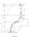
- the inner wall surface of the first sub-inlet section 11' is a concave surface recessed toward the outside of the air guide ring 100', and a tangent plane of the concave surface is produced through a point on the concave surface, and there is an included angle between the tangent plane and a first plane M0 (perpendicular to the axis of the air guide ring 100'). Included angles between different points on the inner wall surface of the first sub-inlet section 11' and the first plane M0 are gradually reduced along the flowing direction of the airflow. As shown in FIG.
- the inner wall surface of the first sub-inlet section 11' has three points P1, P2 and P3 arranged in sequence along the flowing direction of the airflow, where P1 is located at the first inlet end of the first sub-inlet section 11', P3 is a point on an intersection line between the inner wall surface of the first outlet end of the first sub-inlet section 11' and the inner wall surface of the second inlet end of the second sub-inlet section 12', and P2 is located between P1 and P3. Included angles between the tangent planes M1, M2 and M3 at the three points P1, P2 and P3 and the first plane M0 are ⁇ 1, ⁇ 2 and ⁇ 3, respectively, and ⁇ 1> ⁇ 2> ⁇ 3.
- the first sub-inlet section 11' is constructed along the flowing direction of the airflow, and the included angles between the tangent planes at different points on the inner wall surface of the first sub-inlet section 11' and the first plane M0 gradually reduce, so that a ventilation cross-sectional area of the first sub-inlet section 11' is gradually reduced along the flowing direction of the airflow, that is, the first sub-inlet section 11' is gradually contracted, and a flow velocity can be increased when the airflow flows through the first sub-inlet section 11', which is conducive to improving the air intake volume of the air guide ring 100'.
- the inner wall surface of the second sub-inlet section 12' is a convex curved surface protruding toward the outside of the air guide ring 100', and a tangent plane of the convex curved surface is produced through a point on the convex curved surface, and there is an included angle between the tangent plane and the first plane (perpendicular to the axis of the air guide ring 100').
- the included angles between the different points on the inner wall surface of the second sub-inlet section 12' and the first plane M0 gradually increase along the flowing direction of the airflow. As shown in FIG.
- the inner wall surface of the second sub-inlet section 12' is provided with three points P3, P4 and P5 arranged in sequence along the flowing direction of the airflow, where P3 is a point on the intersection line between the inner wall surface of the first outlet end of the first sub-inlet section 11' and the inner wall surface of the second inlet end of the second sub-inlet section 12', P5 is located at the second outlet end of the second sub-inlet section 12', and P4 is located between P3 and P5.
- the included angles between the tangent planes M3, M4 and M5 at the three points P3, P4 and P5 and the first plane M0 are ⁇ 3, ⁇ 4 and ⁇ 5, respectively, and ⁇ 3 ⁇ 4 ⁇ 5.
- the second sub-inlet section 12' is constructed along the flowing direction of the airflow, and included angles between the tangent planes at different points on the inner wall surface of the second sub-inlet section 12' and the first plane M0 gradually increase, so that the inner wall surface of the second sub-inlet section 12' forms a convex curved surface protruding toward the inside of the air guide ring 100', and a ventilation cross-sectional area of the second sub-inlet section 12' can be further reduced, which is conducive to further improving the airflow velocity and the air intake volume.
- the inlet section 1' Compared with the sub-inlet section 1' of which the inner wall surface is a conical surface, by providing the first sub-inlet section 11' of which the inner wall surface is a concave surface and the second sub-inlet section 12' of which the inner wall surface is a convex curved surface, so that the inlet section 1' has better guiding effect on the airflow and improves the air intake volume, and the airflow will smoothly flow along the inner wall surface of the inlet section 1' after entering the inlet section 1', without rebounding after colliding with the inner wall surface of the inlet section 1' to reduce the energy of the airflow, generating turbulence, noise, etc., the stability of the gas flow is relatively high, and the noise generated when the airflow flows through the air guide ring 100' can be effectively reduced.
- the air intake volume of the air guide ring 100' can be increased and the noise of the airflow can be reduced.
- the concave surface of the inner wall surface of the first sub-inlet section 11' is a concave spherical surface
- the convex curved surface of the inner wall surface of the second sub-inlet section 12' is a convex spherical surface
- concave surface of the inner wall surface of the first sub-inlet section 11' and the convex curved surface of the inner wall surface of the second sub-inlet section 12' may also be surfaces of other shapes except the spherical surfaces.
- the included angle ⁇ 1 between the tangent plane of the inner wall surface of the first inlet end and the first plane M0 is 70° to 90°.
- ⁇ 1 may be 70°, 73°, 75°, 78°, 80°, 83°, 85°, 87°, 90°, etc.
- the included angle ⁇ 3 between the tangent plane of the inner wall surface of the first outlet end and the first plane is 35° to 55°, for example, ⁇ 3 can be 35°, 38°, 40°, 42°, 45°, 48°, 50°, 52°, 55°, etc.
- the included angle ⁇ 1 between the tangent plane M1 at the point P1 on the inner wall surface of the first inlet end and the first plane M0 is 70° to 90°.
- the included angle ⁇ 3 between the tangent plane M3 at the point P3 on the inner wall surface of the first outlet end and the first plane M0 is 35° to 55°.
- the included angles between tangent planes at different points on the inner wall surface of the first sub-inlet section 11' and the first plane are between ⁇ 1 and ⁇ 3.
- the included angle ⁇ 2 between the tangent plane M2 at point P2 on the inner wall surface of the first sub-inlet section 11' and the first plane M0 is between ⁇ 1 and ⁇ 3, i.e. ⁇ 1 > ⁇ 2 > ⁇ 3.
- the inner wall surface of the first inlet end of the first sub-inlet section 11' of the air guide ring 100' is not as regular as a circle because of limitation of the structural size of the outdoor unit. Therefore, the included angles between the first plane M0 and tangent planes at a plurality of points on the inner wall surface of the first inlet end of the first sub-inlet section 11' arranged along the circumferential direction of the air guide ring 100' may be different, for example, 80°, 82°, 78°, etc., respectively.
- an overall change trend of the included angle between a tangent plane of the inner wall surface of the first sub-inlet section 11' and the first plane M0 is decreasing, and an overall change trend of the included angle between a tangent plane of the inner wall surface of the second sub-inlet section 12' and the first plane M0 is increasing, which is solely changing from an angle to another angle, and this angle is not fixed, but varies within a certain range.
- a value range of the included angle ⁇ 1 is not limited to 80°-90°, and can be adjusted according to actual needs.
- a value range of included angle ⁇ 3 is not limited to 35°-55°, but can also be adjusted according to actual needs.
- an included angle between a tangent plane of the inner wall surface of the second inlet end and the first plane M0 is equal to the included angle ⁇ 3 between a tangent plane of the inner wall surface of the first outlet end and the first plane M0, and the included angle ⁇ 5 between a tangent plane of the inner wall surface of the second outlet end and the first plane M0 is 80°-100°.
- the included angle between the tangent plane of the inner wall surface of the second inlet end of the second sub-inlet section 12' and the first plane is equal to the included angle between the tangent plane of the inner wall surface of the first outlet end and the first plane.
- the point P3 is the point on the intersection line between the inner wall surface of the first outlet end of the first sub-inlet section 11' and the inner wall surface of the second inlet end of the second sub-inlet section 12', and the tangent plane of the inner wall surface of the first sub-inlet section 11' produced through the point P3 coincides with the tangent plane of the inner wall surface of the second sub-inlet section 12' produced through the point P3, both of which are tangent planes M3.
- the included angle between the tangent plane of the inner wall surface of the second inlet end of the second sub-inlet section 12' and the first plane is equal to the included angle between the tangent plane of the inner wall surface of the first outlet end and the first plane, both of which are ⁇ 3, and ⁇ 3 is 35°-55°.
- the included angle ⁇ 5 between the tangent plane M5 at the point P5 on the inner wall surface of the second outlet end and the first plane M0 is 80°-100°, for example, ⁇ 5 can be 80°, 83°, 85°, 88°, 90°, 93°, 95°, 97°, 100°, etc.
- the included angle ⁇ 5 is 80°-90°, the ventilation cross-sectional area of the second sub-inlet section 12' decreases gradually, and when the included angle ⁇ 5 is 90°-100°, the ventilation cross-sectional area of the second sub-inlet section 12' first decreases gradually and then increases gradually.
- the included angles between the tangent planes at different points on the inner wall surface of the second sub-inlet section 12' and the first plane are between ⁇ 3 and ⁇ 5.
- the included angle ⁇ 4 between the tangent plane M4 at the point P4 on the inner wall surface of the second sub-inlet section 12' and the first plane M0 is between ⁇ 3 and ⁇ 5, i.e., ⁇ 3 ⁇ ⁇ 4 ⁇ ⁇ 5.
- the value range of the included angle ⁇ 5 is not limited to 80°-100°, and can be adjusted according to actual needs.
- a ventilation cross section of the middle section 2' of the air guide ring 100' remains unchanged.
- An inner wall surface of the middle section 2' may be a cylindrical surface so that the ventilation cross-sectional area of the middle section 2' remains unchanged.
- An axis of the cylindrical surface coincides with the axis of the air guide ring 100', and the included angle ⁇ 5 between the tangent plane at point P5 on the inner wall surface of the second outlet end of the second sub-inlet section 12' and the first plane is 90°, so as to achieve a smooth transition and connection between the inner wall surface of the second outlet end of the second sub-inlet section 12' and the inner wall surface of the middle section 2'.
- a ventilation cross-sectional area of the outlet section 3' of the air guide ring 100' gradually increases.
- the ventilation cross-sectional area of the outlet section 3' increases gradually, so as to enlarge an air exit range of the air guide ring 100', reduce the airflow velocity and reduce the noise.
- an included angle ⁇ 6 between a tangent plane of an inner wall surface of the outlet section 3' and the first plane perpendicular to the axis of the air guide ring 100' is 95°-180°.
- the included angle ⁇ 6 between the tangent plane M6 at any point P6 on the inner wall surface of the outlet section 3' and the first plane M0 is 95°-180°.
- ⁇ 6 may be 95°, 100°, 110°, 120°, 130°, 140°, 150°, 160°, 170°, 180°, etc.
- the inner wall surface of the outlet section 3' can be a convex spherical surface protruding toward the inside of the air guide ring 100', and along the flowing direction of the airflow, included angles between tangent planes of the inner wall surface of the outlet section 3' and the first plane perpendicular to the axis of the air guide ring 100' gradually increase, that is, a plurality of different points are arranged in sequence along the flowing direction of the airflow on the inner wall surface of the outlet section 3', and included angles between tangent planes at the plurality of different points and the first plane M0 gradually increase.
- a value range of the included angle ⁇ 6 is not limited to 95°-180°, but can also be adjusted according to actual needs.
- the inner wall surface of the outlet section 3' is not limited to a convex spherical surface protruding toward the inside of the air guide ring 100', but may also be a conical surface or the like.
- a relationship among a height H1 of the inlet section 1', a height H2 of the middle section 2', and a height H3 of the outlet section 3' along the axial direction of the air guide ring 100' is 0.5H2 ⁇ H1 ⁇ 1.5H2, 0.05H2 ⁇ H3 ⁇ 1.5H2.
- a height of the first sub-inlet section 11' is H11
- a height of the second sub-inlet section 12' is H12
- H1 1 may be greater than, less than or equal to H12.
- the height of the middle section 2' is H2
- the height of the outlet section 3' is H3.
- the relationship among H1, H2 and H3 is 0.5H2 ⁇ H1 ⁇ 1.5H2, 0.05H2 ⁇ H3 ⁇ 1.5H2.
- the air guide ring 100' has a good flow guiding effect, stable airflow, and can effectively reduce the energy loss and working noise when the airflow flows in the air guide ring 100'.
- a certain relationship is satisfied between the height H1 of the inlet section 1' and the height H2 of the middle section 2', and a certain relationship is satisfied between the height H3 of the outlet section 3' and the height H2 of the middle section 2'. Therefore, after the height H2 of the middle section 2' is determined, the height H1 of the inlet section 1' and the height H3 of the outlet section 3' can be determined according to the height H2 of the middle section 2', so as to realize the design of the axial height of the air guide ring 100'.
- H1, H2 and H3 are not limited to the above and can be adjusted according to actual needs.
- a relationship between the height H2 of the middle section 2' and an axial height H0 of the fan blades extending into the air guide ring 100' is 0.3H0 ⁇ H2 ⁇ 1.2H0.
- the fan blades of the fan can extend to the middle section 2' of the air guide ring 100', and the axis of the middle section 2' coincides with an axis of the fan blades.
- the height of the middle section 2' is H2
- an axial height of the fan blades is H0.
- the relationship between H2 and H0 is 0.3H0 ⁇ H2 ⁇ 1.2H0.
- the height H2 of the middle section 2' can be determined according to the axial height H0 of the fan blades, and then the height H1 of the inlet section 1' and the height H3 of the outlet section 3' can be determined according to the height H2 of the middle section 2', so that the size of the air guide ring 100' matches a size of the fan blades, so that the air guide ring 100' can achieve good flow guiding effect when the fan works and drives air to flow.
- H0 and H2 are not limited to the above and can be adjusted according to actual needs.
- the air guide ring 100' according to the embodiment of the present application is compared with a common air guide ring, and the results are shown in FIGS. 11-12d .
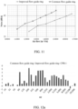
- FIG. 11 is a comparison diagram of air volume noise test data and noise spectrum between the air guide ring (improved air guide ring) 100' according to the embodiment of the present application and the common air guide ring under same working conditions.
- the air guide ring 100' according to the embodiment of the present application and an air volume of the common air guide ring are both 14000 m 3 /h
- the air guide ring 100' according to the embodiment of the present application can reduce the noise by about 4dBA compared with the common air guide ring.
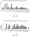
- FIGS. 12a-12d are schematic diagrams of constant percentage bandwidth (CPB) of the noise spectrum of four sides of the air guide ring 100' at frequencies of 20Hz-20000Hz, respectively, with the abscissa as the frequencies and the ordinate as a difference between a noise value of the common air guide and a noise value of the air guide ring (improved air guide ring) 100' according to the embodiment of the present application.
- CB constant percentage bandwidth
- the difference value of the noise value of the common air guide ring minus the noise value of the air guide ring 100' according to the embodiment of the present application is mostly positive, that is, the noise value of the air guide ring 100' of the present application is smaller than the noise value of the common air guide ring. It can be seen that the noise performance of the air guide ring 100' according to the embodiment of the present application is obviously superior to that of the common air guide ring.
- An embodiment of the present application further provides an air conditioner outdoor unit, which includes the air guide ring 100' provided by any of the above embodiments.
- An embodiment of the present application further provides an air conditioner outdoor unit, which includes the air conditioner outdoor unit described above.
- connection may be fixed connection, detachable connection or integrated connection; it may be direct connection, or indirect connection through an intermediary, or may be an internal communication between two elements.
- connection may be fixed connection, detachable connection or integrated connection; it may be direct connection, or indirect connection through an intermediary, or may be an internal communication between two elements.
Landscapes
- Engineering & Computer Science (AREA)
- Chemical & Material Sciences (AREA)
- Combustion & Propulsion (AREA)
- Mechanical Engineering (AREA)
- General Engineering & Computer Science (AREA)
- Structures Of Non-Positive Displacement Pumps (AREA)
- Air-Flow Control Members (AREA)
Abstract
Description
- The present application relates to but is not limited to the field of air conditioning devices, and in particular relates to but is not limited to an air guide ring, an air conditioner outdoor unit and an air conditioner.
- Air output amount of an air conditioner is a key index that affects performance of the air conditioner, and the air guide ring is a key component that affects the air output amount, which is mainly reflected in two aspects: a structure of the air guide ring itself and its cooperation with fan blades. There is an optimal value of an installation gap between the air guide ring and the fan blades. If the gap is too small, the air guide ring and the fan blades will easily contact with each other, which produces friction and even damages the fan blades. If the gap is too large, the air output amount will be reduced. Therefore, designers will adopt the optimal value at the beginning of design.
- The following is a summary of subject matters described in detail herein. This summary is not intended to limit a protection scope of claims.
- An air guide ring is configured to be applicable to an air conditioner outdoor unit. The air guide ring includes an air guide ring body, in which an air guide channel is defined. The air guide ring body is provided with a first limit part and a second limit part. The first limit part and the second limit part are provided to be fitted with a fixing member of the air conditioner outdoor unit for bidirectional limiting, so as to prevent inward contracting deformation and outward expanding deformation of the air guide ring body.
- An air conditioner outdoor unit includes a fixing member and the air guide ring described above. The fixing member is provided with a first limit fitting part and a second limit fitting part. The first limit fitting part is fitted with the first limit part of the air guide ring to obstruct the outward expanding deformation of the air guide ring body. The second limit fitting part is fitted with the second limit part of the air guide ring to obstruct the inward contracting deformation of the air guide ring body.
- An air conditioner includes the above air conditioner outdoor unit.
- An air guide ring includes an inlet section, a middle section and an outlet section arranged in sequence along a flowing direction of airflow. The inlet section includes a first sub-inlet section disposed close to an air inlet end of the air guide ring and a second sub-inlet section disposed close to the middle section. An inner wall surface of the first sub-inlet section is a concave surface recessing toward the outside of the air guide ring, and an inner wall surface of the second sub-inlet section is a convex curved surface protruding toward the inside of the air guide ring. Along the flowing direction of airflow, an included angle between a tangent plane of the inner wall surface of the first sub-inlet section and a first plane perpendicular to an axis of the air guide ring gradually decreases, and an included angle between a tangent plane of the inner wall surface of the second sub-inlet section and the first plane gradually increases.
- An air conditioner outdoor unit includes the above air guide ring.
- An air conditioner includes the above air conditioner outdoor unit.
- Other aspects will become apparent after reading and understanding the drawings and detailed description.
- Accompanying drawings are used to provide a further understanding of technical solutions of the present application, and constitute a portion of the description, They are used together with embodiments of the present application to explain the technical solutions of the present application, and do not constitute a restriction on the technical solutions of the present application.
-
FIG. 1 is a schematic diagram of a structure of an air guide ring according to an embodiment of the present application. -
FIG. 2 is a schematic diagram of an assembly structure of the air guide ring shown inFIG. 1 and fixing members. -
FIG. 3 is an enlarged schematic view of a structure of portion A inFIG. 2 . -
FIG. 4 is a schematic diagram of an exploded structure of the air guide ring and the fixing members shown inFIG. 2 . -
FIG. 5 is a schematic diagram of a structure of the fixing member ofFIG. 2 . -
FIG. 6 is a schematic diagram of a structure of an air conditioner outdoor unit according to an embodiment of the present application. -
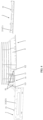
FIG. 7 is a schematic front view of a structure of an air guide ring according to an embodiment of the present application. -
FIG. 8 is a schematic top view of a structure of an air guide ring according to an embodiment of the present application. -
FIG. 9 is a schematic view of a sectional structure ofFIG. 8 taken along B-B. -
FIG. 10 is an enlarged schematic view of a structure of portion C inFIG. 9 . -
FIG. 11 is a comparison diagram of air volume noise test data and noise spectrum of an air guide ring according to an embodiment of the present application. -
FIG. 12a is a schematic diagram of a constant percentage bandwidth (CPB) of a noise spectrum of an air guide ring according to an embodiment of the present application. -
FIG. 12b is a schematic diagram of another constant percentage bandwidth (CPB) of a noise spectrum of an air guide ring according to an embodiment of the present application. -
FIG. 12c is a schematic diagram of yet another constant percentage bandwidth (CPB) of a noise spectrum of an air guide ring according to an embodiment of the present application. -
FIG. 12d is a schematic diagram of still yet another constant percentage bandwidth (CPB) of a noise spectrum of an air guide ring according to an embodiment of the present application. - In the drawings, components represented by reference signs are listed as follows:
- 1-air guide ring, 10-air guide channel, 11-air guide ring body, 111-connecting seat, 112-air guide tube, 113-limit sidewall, 1131-body portion, 1132-bulge part, 114-limit incision, 12-first limit part, 121-first sub-limit part, 122-second sub-limit part, 123-first limit surface, 13-second limit part, 131-second limit surface, 14-notch, 16-reinforcing rib, 17-support part, 18-screw fixing hole,
- 2-fixing member, 21-plate-shaped main body, 211-first limit fitting part, 212-second limit fitting part, 22-bending edge, 221-avoiding recess, 23-fixation lug;
- 100'-air guide ring, 101'-air inlet end, 102'-air outlet end, 1'-inlet section, 11'-first sub-inlet section, 12'-second sub-inlet section, 2'-middle section, 3'-outlet section.
- A clear and complete description of technical solutions of embodiments of the present application will be made below with reference to the accompanying drawings in the embodiments of the present application. It is apparent that described embodiments are only part of the embodiments of the present application, not all of the embodiments of the present application. Based on the embodiments in the present application, all other embodiments obtained by those of ordinary skills in the art without paying creative efforts, fall within the scope of protection of the present application.
- In addition, technical solutions among various embodiments of the present application may be combined with each other, but need to be on a basis that those of ordinary skills in the art can achieve them. When a combination of technical solutions conflicts or cannot be achieved, it should be considered that such combination of technical solutions does not exist and is not within the scope of protection claimed by the present application.
- It should be noted that all directional indications (such as up, down, front, back, etc.) in the embodiments of the present application are only used to explain a relative positional relationship, a motion situation, etc., among various components under a specific posture (as shown in
FIG. 6 ). If the specific posture changes, the directional indications will change accordingly. - During operation of an air conditioner, because of inevitable vibrations, fan blades and an air guide ring are obviously deformed after being stressed, and an installation gap cannot be maintained, while the installation gap is indispensable for maintaining a stable and efficient operation of the air conditioner.
- Based on this, an embodiment of the present application provides an air guide ring, which can reduce a deformation amount of the air guide ring after being stressed, maintain the installation gap between the air guide ring and the fan blades, and improve performance of the air conditioner.
- As shown in
FIG. 1 , an embodiment of the present application provides anair guide ring 1, which can be used for an air conditioner outdoor unit. Theair guide ring 1 is provided to include an airguide ring body 11, and the integral airguide ring body 11 is annular. Anair guide channel 10 is defined inside the airguide ring body 11, and theair guide channel 10 has an air inlet and an air outlet. Theair guide ring 1 can be fitted with a fan, and fan blades of the fan can extend into theair guide channel 10 of theair guide ring 1, so that when the fan is working, airflow can enter from the air inlet, flow through theair guide channel 10, and finally be discharged from the air outlet. A flowing direction of the airflow is shown by the arrows inFIG. 1 , with the air inlet of theair guide channel 10 on the lower side and the air outlet of theair guide channel 10 on the upper side. - As shown in
FIGS. 1-4 , the airguide ring body 11 is provided with two limit parts which are afirst limit part 12 and asecond limit part 13 respectively. Both thefirst limit part 12 and thesecond limit part 13 can be fitted with a fixingmember 2 for limiting. For example, thefirst limit part 12 can be fitted with the first limitfitting part 211 of the fixingmember 2 of the air conditioner outdoor unit for limiting, so as to prevent radially outward expanding deformation of the airguide ring body 11. Thesecond limit part 13 can be fitted with the second limitfitting part 212 of the fixingmember 2 to prevent radially inward contracting deformation of the airguide ring body 11. That is, the two limit parts can be fitted to limit the airguide ring body 11 bidirectionally, which can limit the radially outward expanding deformation and the radially inward contracting deformation of the airguide ring body 11. - Since the air
guide ring body 11 is integrally annular, when a portion of the airguide ring body 11 expands and deforms radially outward, other portions of the airguide ring body 11 will contract and deform radially inward; or when a portion of the airguide ring body 11 contracts and deforms radially inward, other portions of the airguide ring body 11 will expand and deform radially outward. Thefirst limit part 12 and thesecond limit part 13 limit the contraction and expanding deformation of the airguide ring body 11, which facilitates reducing the deformation amount of theair guide ring 1 after being stressed and maintaining shape stability of the airguide ring body 11, so as to maintain the installation gap between theair guide ring 1 and the fan blades during the operation of the air conditioner, thus avoiding mutual contact between theair guide ring 1 and the fan blades and even the damage of the fan blades caused by a too small gap and reduction in air output amount caused by a too large gap, and improving the performance of the air conditioner. - As a comparison, a common air guide ring is easy to deform during installation, which affects the fitting between an air wheel and the air guide ring, causing leakage loss at the tips of air wheel blades to increase, resulting in deterioration of performance of the fan system. For the
air guide ring 1 according to the embodiment of the present application, by providing thefirst limit part 12 and thesecond limit part 13, the deformation of theair guide ring 1 is avoided, the fitting between the air wheel and theair guide ring 1 is ensured, the leakage loss at the tips of the air wheel blades is reduced, the performance of the fan system is ensured, thereby avoiding failure of the fan system. - In some exemplary embodiments, as shown in
FIGS. 1-4 , thesecond limit part 13 is disposed radially outward of the first limit part 12 (i.e., away from a center of the air guide ring body 11), and a radial interval is provided between thesecond limit part 13 and thefirst limit part 12. Thesecond limit part 13 and thefirst limit part 12 can be clamped on two sides of the fixingmember 2. - An outside wall surface of the first limit part 12 (i.e., a side wall surface on a side away from the center of the air guide ring body 11) may form a
first limit surface 123, and an inside wall surface of the second limit part 13 (i.e., a side wall surface on a side close to the center of the air guide ring body 11) may form asecond limit surface 131. Thefirst limit surface 123 and thesecond limit surface 131 may be parallel to each other. Thesecond limit surface 131 is located radially outward of thefirst limit surface 123, and a radial interval is provided between thefirst limit surface 123 and thesecond limit surface 131. After the fixingmember 2 is inserted between thesecond limit part 13 and thefirst limit part 12, a first limitfitting part 211 of the fixingmember 2 can abut against thefirst limit surface 123 for limiting, and a second limitfitting part 212 of the fixingmember 2 can abut against thesecond limit surface 131 for limiting, so as to prevent radially outward expanding deformation and radially inward contracting deformation of the airguide ring body 11 and in turn reduce the deformation amount of theair guide ring 1 after being stressed. - In some exemplary embodiments, as shown in
FIG. 1 , thesecond limit part 13 and thefirst limit part 12 are provided to be offset along a circumferential direction of the airguide ring body 11, that is, thesecond limit part 13 and thefirst limit part 12 are located at different circumferential positions on the airguide ring body 11. - Apparently, the
second limit part 13 and thefirst limit part 12 may also be provided to be arranged along the circumferential direction of the airguide ring body 11, that is, thesecond limit part 13 and thefirst limit part 12 may be located at a same circumferential position of the airguide ring body 11. - In some exemplary embodiments, as shown in
FIG. 1 , the two limit parts are provided to be offset along the circumferential direction of the airguide ring body 11, and thefirst limit part 12 is provided to include two sub-limit parts, i.e., a firstsub-limit part 121 and a secondsub-limit part 122. Thesecond limit part 13 is arranged between the two sub-limit parts, that is, the secondsub-limit part 122, thesecond limit part 13 and the firstsub-limit part 121 are arranged in sequence along the circumferential direction of the airguide ring body 11. - After the fixing
member 2 is inserted into the radial interval between thefirst limit part 12 and thesecond limit part 13, two ends of the first limitfitting part 211 of the fixingmember 2 can respectively abut against the two sub-limit parts for limiting, and the second limitfitting part 212 of the fixingmember 2 can abut against thesecond limit part 13 located in the middle for limiting, which facilitates achieving the limit fitting between theair guide ring 1 and the fixingmember 2. - In some exemplary embodiments, as shown in
FIG. 1 , anotch 14 is provided at one side of the airguide ring body 11, thenotch 14 is located at a side close to the air inlet, and the two sub-limit parts of thefirst limit part 12 are respectively located on two sides of thenotch 14. The airguide ring body 11 is provided with abulge part 1132 extending along an axial direction toward the notch 14 (i.e., extending downward), and thebulge part 1132 can form thesecond limit part 13 such that thesecond limit part 13 is positioned between the secondsub-limit part 122 and the firstsub-limit part 121, thereby realizing the offset arrangement of the two limit parts. - In addition, the arrangement of the
notch 14 is conducive to reducing a size of theair guide ring 1, so that the size of theair guide ring 1 can be maximized in the limited space in the air conditioner outdoor unit, thereby maximizing the size of the air wheel and improving the performance of the fan. - The
bulge part 1132 may have a rectangular shape, a circular shape, etc. Thebulge part 1132 and thefirst limit part 12 may form an embedded assembly structure. During the installation of theair guide ring 1, the fixingmember 2 may extend between thebulge part 1132 and thefirst limit part 12, so as to effectively position theair guide ring 1 and prevent theair guide ring 1 from being out of position or deforming under stress. - In some exemplary embodiments, as shown in
FIG. 1 , a sidewall surface of the bulge part 1132 (second limit part 13) is provided with a reinforcingrib 16. The reinforcingrib 16 may be provided on an outside wall surface of the bulge part 1132 (i.e., a side wall surface at a side away from the center of the air guide ring body 11), or may be provided on an inside wall surface of the bulge part 1132 (i.e., a side wall surface at a side close to the center of the air guide ring body 11), or the reinforcingrib 16 may be provided on both the inside wall surface and the outside wall surface of thebulge part 1132. The reinforcingrib 16 is provided to extend along the axial direction of the airguide ring body 11 or along the circumferential direction of the airguide ring body 11. Alternatively, a plurality of reinforcingribs 16 are provided, part of the reinforcingribs 16 can extend along the axial direction of the airguide ring body 11, part of the reinforcingribs 16 extend along the circumferential direction of the airguide ring body 11, and the reinforcingribs 16 extending along the axial direction and the reinforcingribs 16 extending along the circumferential direction cross each other in a grid shape. - The
bulge part 1132 forming thesecond limit part 13 is provided with the reinforcingribs 16 to enhance the strength of thebulge part 1132, thereby enhancing a limiting effect of thesecond limit part 13 and preventing theair guide ring 1 from being deformed under stress. - In some exemplary embodiments, a plurality of the
first limit parts 12 are provided and are arranged along the circumferential direction of the airguide ring body 11, such as uniformly arranged. A plurality of thesecond limit parts 13 are also provided and are arranged along the circumferential direction of the airguide ring body 11, for example, thesecond limit parts 13 are uniformly arranged. The number of thesecond limit parts 13 and the number of thefirst limit parts 12 are equal, and they cooperate with each other in one-to-one correspondence. - The
first limit part 12 and the correspondingsecond limit part 13 can cooperate with each other to implement the bidirectional limiting against the inward contracting deformation and the outward expanding deformation of the airguide ring body 11. The plurality offirst limit parts 12 and the corresponding plurality ofsecond limit parts 13 cooperate with each other to better limit the deformation of the airguide ring body 11. - As can be seen from
FIGS. 1 and4 , twosecond limit parts 13 and twofirst limit parts 12 are provided. One of thefirst limit parts 12 and a correspondingsecond limit part 13 are located at a front side of the airguide ring body 11 and can be fitted with a fixingmember 2 located at the front side. The other of thefirst limit parts 12 and a correspondingsecond limit part 13 are located at a rear side of the airguide ring body 11 and can be fitted with a fixingmember 2 located at the rear side. Alternatively, twofirst limit parts 12 may be provided at the left side and the right side of the airguide ring body 11, respectively, and twosecond limit parts 13 may be provided at the left side and the right side of the airguide ring body 11, respectively. - It should be understood that the number of the
second limit parts 13 and the number of thefirst limit parts 12 provided are not limited to two and may be set as required. - In some exemplary embodiments, as shown in
FIGS. 1-3 , the airguide ring body 11 is provided withsupport parts 17, and thesupport parts 17 are provided to extend along the circumferential direction of the airguide ring body 11. Thesupport parts 17 may be support ribs disposed on the outside wall surface of the airguide ring body 11. The support ribs may be provided as an integral structure, or thesupport parts 17 may include a plurality of support ribs arranged at intervals. - The
support part 17 can be supported on the fixingmember 2 to support and position theair guide ring 1 and the fixingmember 2. - The
second limit part 13 and thefirst limit part 12 are provided to be located at a lower side of the support part 17 (i.e., at a side close to the air inlet of the air guide channel 10), so that the fixingmember 2 is inserted between thefirst limit part 12 and thesecond limit part 13 from the side close to the air inlet until the fixingmember 2 abuts against thesupport part 17, thus realizing the limit fitting and support fitting between the airguide ring body 11 and the fixingmember 2. - In some exemplary embodiments, the side wall of the air
guide ring body 11 is provided with a fixation part which can be fixedly connected with the fixingmember 2. As shown inFIGS. 1-3 , the fixation part may be ascrew fixing hole 18, and the airguide ring body 11 and the fixingmember 2 may be fixedly connected to each other by screws. A plurality (e.g. two) ofscrew fixing holes 18 may be provided to securely fix the airguide ring body 11 and the fixingmember 2 by a plurality of screws. - As shown in
FIGS. 2-4 , the fixation part is disposed at an upper side of the support part 17 (i.e., at a side close to the air outlet of the air guide channel 10), and afixation lug 23 may be disposed on an upper part of the fixingmember 2, so that fixing is performed with a screw after a threaded hole on thefixation lug 23 coincides with a screw axis of the airguide ring body 11. - The
air guide ring 1 and the fixingmember 2 are axially supported and positioned by thesupport part 17, and are radially limited by thefirst limit part 12 and thesecond limit part 13 at the lower side, and are fixed by screws at the upper side, so that the fixation between theair guide ring 1 and the fixingmember 2 is stable. Apparently, the positions of thesecond limit part 13 and thefirst limit part 12 are not limited to being at the lower side of thesupport part 17, and the position of the fixation part is not limited to being at the upper side of thesupport part 17, which can be adjusted as required. - In some exemplary embodiments, the air
guide ring body 11 is provided with a limit protrusion that can be used for limiting in cooperation with a limit hole in the fixingmember 2. Alternatively, the airguide ring body 11 is provided with a limit hole, and the limit hole can be fitted with the limit protrusion on the fixingmember 2 for limiting. - The air
guide ring body 11 and the fixingmember 2 are respectively provided with a limit protrusion and a limit hole, so that the airguide ring body 11 and the fixingmember 2 are limited through the fitting between the limit protrusion and the limit hole, so that the airguide ring body 11 and the fixingmember 2 are fixed to each other. - In some exemplary embodiments, as shown in
FIG. 1 , the airguide ring body 11 is provided to include a connectingseat 111 and anair guide tube 112. The connectingseat 111 has a first air guide channel, theair guide tube 112 is provided in a hollow cylindrical shape, and theair guide tube 112 has a second air guide channel. The connectingseat 111 may be provided in a necking shape, and a first end of the connecting seat 111 (i.e., a necking end, the upper end inFIG. 1 ) is connected with theair guide tube 112. For example, the connectingseat 111 and theair guide tube 112 may be integrally formed such that the first air guide channel in the connectingseat 111 and the second air guide channel in theair guide tube 112 are connected to each other to form theair guide channel 10. The connectingseat 111 is disposed at a side close to the air inlet such that a second end of the connecting seat 111 (i.e., a flared end, the lower end inFIG. 1 ) forms the air inlet of theair guide channel 10, so that airflow enters the first air guide channel from the flared end and then flows out of the necking end and flows into the second air guide channel. - The connecting
seat 111 can be fixedly fitted with the fixingmember 2 to implement the fixation of theair guide ring 1. - In some exemplary embodiments, as shown in
FIG. 1 , the connectingseat 111 is provided to include twolimit sidewalls 113 oppositely arranged, and eachlimit sidewall 113 is provided to include afirst limit part 12 and asecond limit part 13. Thefirst limit part 12 and thesecond limit part 13 are disposed at intervals along the radial direction of the airguide ring body 11 and at least partially coincide along the axial direction of the airguide ring body 11, and the radial interval between thefirst limit part 12 and thesecond limit part 13 of eachlimit sidewall 113 is used to clamp a fixingmember 2 so that the fixingmember 2 is fitted with thefirst limit part 12 and thesecond limit part 13 for limiting to prevent radially outward expanding deformation and radially inward contracting deformation of the airguide ring body 11. - In some exemplary embodiments, as shown in
FIG. 1 , thelimit sidewall 113 is provided to include abody portion 1131 and abulge part 1132 protruding outwardly from thebody portion 1131. Thebody portion 1131 of thelimit sidewall 113 may form thefirst limit part 12, thebulge part 1132 may form thesecond limit part 13, and alimit incision 114 is formed between thebody portion 1131 and thebulge part 1132. The limitingincision 114 is used for clamping the fixingmember 2. - Since the
bulge part 1132 can protrude outward from the middle of thebody portion 1131, thebody portion 1131 at two ends of thelimit sidewall 113 forms thefirst limit part 12, and thebulge part 1132 at the middle of thelimit sidewall 113 forms thesecond limit part 13. - The
first limit part 12 formed by thebody portion 1131 of thelimit sidewall 113 can be abutted against and fitted with the fixingmember 2 to prevent the radially outward expanding deformation of the airguide ring body 11. Thesecond limit part 13 formed by thebulge part 1132 can be abutted against and fitted with the fixingmember 2 to prevent the radially inward contracting deformation of the airguide ring body 11. - As shown in
FIG. 1 , reinforcingribs 16 extending along the axial direction and/or the circumferential direction of the airguide ring body 11 are provided on the outer wall surface of other portions of the airguide ring body 11 except for the bulge part 1132 (the second limit part 13), and the reinforcingribs 16 extending along the axial direction and the reinforcingribs 16 extending along the circumferential direction cross each other to form a grid shape. The reinforcingribs 16 on the airguide ring body 11 can abut against the first limitfitting part 211 of the fixingmember 2 for limiting, so as to further reduce the deformation amount of the airguide ring body 11. - As shown in
FIG. 6 , an embodiment of the present application further provides an air conditioner outdoor unit. The air conditioner outdoor unit is provided to include theair guide ring 1 of any of the above embodiments. The air conditioner outdoor unit can be a cabinet unit. - It should be understood that the
air guide ring 1 according to the embodiment of the present application can also be applied to other products other than the air conditioner outdoor unit. - As shown in
FIG. 1 , the air conditioner outdoor unit is provided to further include a fixingmember 2. As shown inFIGS. 2-5 , the fixingmember 2 is provided with the first limitfitting part 211, which can be fitted with thefirst limit part 12 of theair guide ring 1 for limiting, so as to prevent radially outward expanding deformation of the airguide ring body 11. The fixingmember 2 is further provided with the second limitfitting part 212, which can be fitted with thesecond limit part 13 of theair guide ring 1 for limiting, so as to prevent radially inward contracting deformation of the airguide ring body 11. - Through the fitting between the
first limit part 12 and the first limitfitting part 211, and the fitting between thesecond limit part 13 and the second limitfitting part 212, the deformation amount of theair guide ring 1 after being stressed can be reduced, so that the installation gap between theair guide ring 1 and the fan blades can be maintained during operation of the air conditioner, and the performance of the air conditioner can be improved. - In some exemplary embodiments, as shown in
FIGS. 2-5 , the fixingmember 2 is provided to include a plate-shapedmain body 21, and the plate-shapedmain body 21 has two opposite plate surfaces to form the first limitfitting part 211 and the second limitfitting part 212, respectively. When the fixingmember 2 is assembled with theair guide ring 1, the plate-shapedmain body 21 of the fixingmember 2 is disposed so that it can be clamped (or inserted) between thefirst limit part 12 and thesecond limit part 13, so that a plate surface at one side of the plate-shaped main body 21 (a side close to the center of the air guide ring body 11) abuts against thefirst limit surface 123 of thefirst limit part 12 for limiting, and a plate surface at the other side of the plate-shaped main body 21 (a side away from the center of the air guide ring body 11) abuts against thesecond limit surface 131 of thesecond limit part 13 for limiting. The plate surface at one side of the plate-shapedmain body 21 can be in direct contact with thefirst limit surface 123 and they can be in surface contact with each other. The plate surface at the other side of the plate-shapedmain body 21 can be in direct contact with thesecond limit surface 131 and they can be in surface contact with each other. The surface contact increases a contact area between the fixingmember 2 and the airguide ring body 11, and enhances the limiting effect on the airguide ring body 11. Alternatively, there may be line contact between the plate surface at one side of the plate-shapedmain body 21 and the first limit surface, and line contact between the plate surface at the other side of the plate-shapedmain body 21 and the second limit surface. - In some exemplary embodiments, as shown in
FIGS. 2-5 , the fixingmember 2 is provided to further include a bendingedge 22 formed by bending one end (upper end) of the plate-shapedmain body 21. The bendingedge 22 is provided to be bent toward a side where the center of theair guide ring 1 is located, and an included angle between the bendingedge 22 and the plate-shapedmain body 21 may be about 90 degrees, and the bendingedge 22 may be used to support theair guide ring 1. Thesupport part 17 of theair guide ring 1 is provided to be supported on the bendingedge 22, so as to support and position theair guide ring 1 and the fixingmember 2. - The bending
edge 22 is provided with anavoidance recess 221, which can be used for avoidance on the one hand, and facilitate bending and forming the bendingedge 22 on the other hand. - In some exemplary embodiments, as shown in
FIGS. 2-5 , the fixingmember 2 is provided to further include afixation lug 23 formed by bending the bendingedge 22. Thefixation lug 23 is provided to be bent toward a side (i.e. the upper side) away from the plate-shapedmain body 21, and an included angle between thefixation lug 23 and the bendingedge 22 may be about 90 degrees. - The
fixation lug 23 can be used for fixation with theair guide ring 1, and thefixation lug 23 can be provided with a threaded hole. When fixing, thefixation lug 23 can extend into the airguide ring body 11 from a side where the air inlet is located, and a screw can be screwed with the threaded hole on thefixation lug 23 after passing through thescrew fixing hole 18 on the airguide ring body 11, so as to implement the fixed connection between theair guide ring 1 and the fixingmember 2. - A plurality (e.g. two) of fixation lugs 23 may be provided for securely fixing the
air guide ring 1 and the fixingmember 2 by a plurality of screws. - In some exemplary embodiments, the
air guide ring 1 is a plastic member, and the fixingmember 2 is a sheet metal member. The fixingmember 2 has strong structural strength and is not prone to deformation, so theair guide ring 1 can be limited by the fixingmember 2 to prevent theair guide ring 1 from deforming. - Apparently, materials of the
air guide ring 1 and the fixingmember 2 are not limited to the above, and can be adjusted according to actual needs. - In some exemplary embodiments, the fixing
member 2 is provided as a motor beam for fixing a motor, i.e. the motor beam may be used for fixing both the motor and theair guide ring 1, thus having dual functions. - Selecting the motor beam for fixing the motor as the fixing
member 2 for fixing and limiting theair guide ring 1 is conducive to reducing the number of components of the air conditioner outdoor unit, simplifying the structure of the product and reducing the cost. - Apparently, the fixing
member 2 can also be separately provided for fixing theair guide ring 1. - In some exemplary embodiments, two fixing
members 2 are provided. The motor beam may include a front motor beam located at the front side and a rear motor beam located at the rear side. The two fixingmembers 2 can be a front motor beam and a rear motor beam, respectively. Each of the front motor beam and the rear motor beam is provided with a bendingedge 22. When the front motor beam and the rear motor beam are installed in place, the connectingseat 111 of theair guide ring 1 is placed on the bending edges 22 and positioned by the limit holes and the limit protrusions. At this time, the airguide ring body 11 is located between the front motor beam and the rear motor beam, and the front and rear bulge parts 1132 (second limit parts 13) of the airguide ring body 11 respectively clamp the front motor beam and the rear motor beam from the front and rear sides. Finally, the airguide ring body 11 is fixed with the front motor beam by screws and the airguide ring body 11 is fixed with the rear motor beam by screws. - In contrast to some cases, in which the
air guide ring 1 is supported on the bendingedge 22 of the motor beam and fixed on the bendingedge 22 of the motor beam by vertically arranged screws (arranged along the axial direction of the air guide ring 1), in the embodiment of the present application, theair guide ring 1 is supported on the bendingedge 22 of the motor beam, and thefirst limit part 12 and thesecond limit part 13 are clamped on the two sides of the plate-shapedmain body 21 of the motor beam, and theair guide ring 1 is fixed with the fixation lugs 23 of the motor beam by transversely arranged screws. In the embodiment of the present application, the motor beam can better fix and limit theair guide ring 1, so that theair guide ring 1 is firmly fixed and the deformation of theair guide ring 1 is prevented. - In the embodiment of the application, the
first limit part 12 and thesecond limit part 13 are additionally provided for limit fitting with the motor beam, which can resist the deformation of the airguide ring body 11, improve the stress condition at fixing screws, improve a force transmission mode and a force conduction path of theair guide ring 1, reduce the deformation amount of theair guide ring 1 after being stressed, and is conducive to maintaining the structural stability of theair guide ring 1, thereby maintaining the installation gap between theair guide ring 1 and the fan blades, so that the air conditioner outdoor unit can maintain efficient and stable operation. - In some exemplary embodiments, the
notch 14 is disposed close to a short side of the air conditioner outdoor unit. - An axis of the
air guide ring 1 is arranged vertically, and the air inlet can face downward and the air outlet can face upward, so that the outdoor unit can achieve downward air inlet and upward air outlet. The arrangement of thenotch 14 is conducive to reducing the volume of theair guide ring 1. Thenotch 14 is arranged close to a short side of a casing of the outdoor unit (for example, a shorter one of the sides of the casing along the front-rear direction and along the left-right direction, for example, the side along the front-back direction), so that the size of theair guide ring 1 can be enlarged as much as possible in the limited space in the casing, and the size of the air wheel can be maximized, thus benefiting the performance of the fan system, improving the air intake volume of the fan and reducing the working noise. - An embodiment of the present application further provides an air conditioner, which includes the air conditioner outdoor unit described in any of the above embodiments.
- An embodiment of the present application further provides an air guide ring (or flow guide ring) 100', as shown in
FIGS. 7-10 , including an inlet section 1', a middle section 2' and an outlet section 3' arranged in sequence along a flowing direction of an airflow. - The air guide ring 100' can guide the airflow, make the flowing direction of the airflow regular, and reduce energy loss of airflow. The air guide ring body of the air guide ring 100' may include the inlet section 1', the middle section 2' and the outlet section 3' arranged in sequence along the flowing direction of the airflow. The airflow flows along the axial direction of the air guide ring 100'. Therefore, the inlet section 1', the middle section 2' and the outlet section 3' are arranged in sequence along the axial direction of the air guide ring 100'. The airflow can flow into an air inlet end 101' of the air guide ring 100'. The airflow first flows through the inlet section 1', then passes through the middle section 2' and the outlet section 3' in sequence, and finally flows out of an air outlet end 102' of the air guide ring 100', so that a direction from the inlet section 1' to the outlet section 3' is the flowing direction of the airflow.
- In the air guide ring 100', the inlet section 1' includes two sub-inlet sections 1' connected in sequence, i.e., a first sub-inlet section 11' and a second sub-inlet section 12'. The first sub-inlet section 11' is close to the air inlet end 101' of the air guide ring 100', and the second sub-inlet section 12' is close to the middle section 2', so that the airflow flows first through the first sub-inlet section 11' and then through the second sub-inlet section 12' when flowing into the air guide ring 100'.
- As shown in
FIG. 10 , the first sub-inlet section 11' includes a first inlet end close to the air inlet end 101' and a first outlet end away from the air inlet end 101', and the second sub-inlet section 12' includes a second inlet end close to the air inlet end 101' and a second outlet end away from the air inlet end 101'. The second inlet end of the second sub-inlet section 12' is smoothly transitioned to and connected with the first outlet end of the first sub-inlet section 11'. The first outlet end of the first sub-inlet section 11' is smoothly transitioned to and connected with the second inlet end of the second sub-inlet section 12', so that an inner wall surface of the first sub-inlet section 11' is smoothly transitioned to and connected with an inner wall surface of the second sub-inlet section 12', and the flow of airflow is unhindered and stable, so as to avoid turbulence when the airflow flows through a connecting portion between the first sub-inlet section 11' and the second sub-inlet section 12', which causes greater energy loss of the airflow, affecting the guiding effect of the air guide ring 100' and increasing noise. - As shown in
FIG. 10 , the inner wall surface of the first sub-inlet section 11' is a concave surface recessed toward the outside of the air guide ring 100', and a tangent plane of the concave surface is produced through a point on the concave surface, and there is an included angle between the tangent plane and a first plane M0 (perpendicular to the axis of the air guide ring 100'). Included angles between different points on the inner wall surface of the first sub-inlet section 11' and the first plane M0 are gradually reduced along the flowing direction of the airflow. As shown inFIG. 10 , the inner wall surface of the first sub-inlet section 11' has three points P1, P2 and P3 arranged in sequence along the flowing direction of the airflow, where P1 is located at the first inlet end of the first sub-inlet section 11', P3 is a point on an intersection line between the inner wall surface of the first outlet end of the first sub-inlet section 11' and the inner wall surface of the second inlet end of the second sub-inlet section 12', and P2 is located between P1 and P3. Included angles between the tangent planes M1, M2 and M3 at the three points P1, P2 and P3 and the first plane M0 are α1, α2 and α3, respectively, and α1>α2>α3. - The first sub-inlet section 11' is constructed along the flowing direction of the airflow, and the included angles between the tangent planes at different points on the inner wall surface of the first sub-inlet section 11' and the first plane M0 gradually reduce, so that a ventilation cross-sectional area of the first sub-inlet section 11' is gradually reduced along the flowing direction of the airflow, that is, the first sub-inlet section 11' is gradually contracted, and a flow velocity can be increased when the airflow flows through the first sub-inlet section 11', which is conducive to improving the air intake volume of the air guide ring 100'.
- As shown in
FIG. 10 , the inner wall surface of the second sub-inlet section 12' is a convex curved surface protruding toward the outside of the air guide ring 100', and a tangent plane of the convex curved surface is produced through a point on the convex curved surface, and there is an included angle between the tangent plane and the first plane (perpendicular to the axis of the air guide ring 100'). The included angles between the different points on the inner wall surface of the second sub-inlet section 12' and the first plane M0 gradually increase along the flowing direction of the airflow. As shown inFIG. 10 , the inner wall surface of the second sub-inlet section 12' is provided with three points P3, P4 and P5 arranged in sequence along the flowing direction of the airflow, where P3 is a point on the intersection line between the inner wall surface of the first outlet end of the first sub-inlet section 11' and the inner wall surface of the second inlet end of the second sub-inlet section 12', P5 is located at the second outlet end of the second sub-inlet section 12', and P4 is located between P3 and P5. The included angles between the tangent planes M3, M4 and M5 at the three points P3, P4 and P5 and the first plane M0 are α3, α4 and α5, respectively, and α3<α4<α5. - The second sub-inlet section 12' is constructed along the flowing direction of the airflow, and included angles between the tangent planes at different points on the inner wall surface of the second sub-inlet section 12' and the first plane M0 gradually increase, so that the inner wall surface of the second sub-inlet section 12' forms a convex curved surface protruding toward the inside of the air guide ring 100', and a ventilation cross-sectional area of the second sub-inlet section 12' can be further reduced, which is conducive to further improving the airflow velocity and the air intake volume.
- Compared with the sub-inlet section 1' of which the inner wall surface is a conical surface, by providing the first sub-inlet section 11' of which the inner wall surface is a concave surface and the second sub-inlet section 12' of which the inner wall surface is a convex curved surface, so that the inlet section 1' has better guiding effect on the airflow and improves the air intake volume, and the airflow will smoothly flow along the inner wall surface of the inlet section 1' after entering the inlet section 1', without rebounding after colliding with the inner wall surface of the inlet section 1' to reduce the energy of the airflow, generating turbulence, noise, etc., the stability of the gas flow is relatively high, and the noise generated when the airflow flows through the air guide ring 100' can be effectively reduced.
- Therefore, by providing the first sub-inlet section 11' and the second sub-inlet section 12' in the air guide ring 100' according to the embodiment of the present application, the air intake volume of the air guide ring 100' can be increased and the noise of the airflow can be reduced.
- In some exemplary embodiments, as shown in
FIG. 10 , the concave surface of the inner wall surface of the first sub-inlet section 11' is a concave spherical surface, and the convex curved surface of the inner wall surface of the second sub-inlet section 12' is a convex spherical surface. - It should be understood that the concave surface of the inner wall surface of the first sub-inlet section 11' and the convex curved surface of the inner wall surface of the second sub-inlet section 12' may also be surfaces of other shapes except the spherical surfaces.
- In some exemplary embodiments, as shown in
FIG. 10 , in the first sub-inlet section 11', the included angle α1 between the tangent plane of the inner wall surface of the first inlet end and the first plane M0 is 70° to 90°. For example, α1 may be 70°, 73°, 75°, 78°, 80°, 83°, 85°, 87°, 90°, etc. In the first sub-inlet section 11', the included angle α3 between the tangent plane of the inner wall surface of the first outlet end and the first plane is 35° to 55°, for example, α3 can be 35°, 38°, 40°, 42°, 45°, 48°, 50°, 52°, 55°, etc. - The included angle α1 between the tangent plane M1 at the point P1 on the inner wall surface of the first inlet end and the first plane M0 is 70° to 90°. The included angle α3 between the tangent plane M3 at the point P3 on the inner wall surface of the first outlet end and the first plane M0 is 35° to 55°. Along a direction from the first inlet end towards the first outlet end, i.e. along the flowing direction of the airflow, the included angles between tangent planes at different points on the inner wall surface of the first sub-inlet section 11' and the first plane are between α1 and α3. For example, the included angle α2 between the tangent plane M2 at point P2 on the inner wall surface of the first sub-inlet section 11' and the first plane M0 is between α1 and α3, i.e. α1 > α2 > α3.
- When the air guide ring 100' is applied to a product (such as an air conditioner outdoor unit), the inner wall surface of the first inlet end of the first sub-inlet section 11' of the air guide ring 100' is not as regular as a circle because of limitation of the structural size of the outdoor unit. Therefore, the included angles between the first plane M0 and tangent planes at a plurality of points on the inner wall surface of the first inlet end of the first sub-inlet section 11' arranged along the circumferential direction of the air guide ring 100' may be different, for example, 80°, 82°, 78°, etc., respectively. However, along the flowing direction of the airflow, an overall change trend of the included angle between a tangent plane of the inner wall surface of the first sub-inlet section 11' and the first plane M0 is decreasing, and an overall change trend of the included angle between a tangent plane of the inner wall surface of the second sub-inlet section 12' and the first plane M0 is increasing, which is solely changing from an angle to another angle, and this angle is not fixed, but varies within a certain range.
- It should be understood that a value range of the included angle α1 is not limited to 80°-90°, and can be adjusted according to actual needs. A value range of included angle α3 is not limited to 35°-55°, but can also be adjusted according to actual needs.
- In some exemplary embodiments, as shown in
FIG. 10 , in the second sub-inlet section 12', an included angle between a tangent plane of the inner wall surface of the second inlet end and the first plane M0 is equal to the included angle α3 between a tangent plane of the inner wall surface of the first outlet end and the first plane M0, and the included angle α5 between a tangent plane of the inner wall surface of the second outlet end and the first plane M0 is 80°-100°. - Since the second inlet end of the second sub-inlet section 12' is smoothly transitioned to and connected with the first outlet end of the first sub-inlet section 11', the included angle between the tangent plane of the inner wall surface of the second inlet end of the second sub-inlet section 12' and the first plane is equal to the included angle between the tangent plane of the inner wall surface of the first outlet end and the first plane. As shown in the FIG. ?, the point P3 is the point on the intersection line between the inner wall surface of the first outlet end of the first sub-inlet section 11' and the inner wall surface of the second inlet end of the second sub-inlet section 12', and the tangent plane of the inner wall surface of the first sub-inlet section 11' produced through the point P3 coincides with the tangent plane of the inner wall surface of the second sub-inlet section 12' produced through the point P3, both of which are tangent planes M3. Therefore, the included angle between the tangent plane of the inner wall surface of the second inlet end of the second sub-inlet section 12' and the first plane is equal to the included angle between the tangent plane of the inner wall surface of the first outlet end and the first plane, both of which are α3, and α3 is 35°-55°.
- The included angle α5 between the tangent plane M5 at the point P5 on the inner wall surface of the second outlet end and the first plane M0 is 80°-100°, for example, α5 can be 80°, 83°, 85°, 88°, 90°, 93°, 95°, 97°, 100°, etc. When the included angle α5 is 80°-90°, the ventilation cross-sectional area of the second sub-inlet section 12' decreases gradually, and when the included angle α5 is 90°-100°, the ventilation cross-sectional area of the second sub-inlet section 12' first decreases gradually and then increases gradually.
- Along a direction from the second inlet end of the second sub-inlet section 12' towards the second outlet end, i.e. along the flowing direction of the airflow, the included angles between the tangent planes at different points on the inner wall surface of the second sub-inlet section 12' and the first plane are between α3 and α5. For example, the included angle α4 between the tangent plane M4 at the point P4 on the inner wall surface of the second sub-inlet section 12' and the first plane M0 is between α3 and α5, i.e., α3 < α4 < α5.
- It should be understood that the value range of the included angle α5 is not limited to 80°-100°, and can be adjusted according to actual needs.
- In some exemplary embodiments, as shown in
FIG. 10 , a ventilation cross section of the middle section 2' of the air guide ring 100' remains unchanged. - An inner wall surface of the middle section 2' may be a cylindrical surface so that the ventilation cross-sectional area of the middle section 2' remains unchanged. An axis of the cylindrical surface coincides with the axis of the air guide ring 100', and the included angle α5 between the tangent plane at point P5 on the inner wall surface of the second outlet end of the second sub-inlet section 12' and the first plane is 90°, so as to achieve a smooth transition and connection between the inner wall surface of the second outlet end of the second sub-inlet section 12' and the inner wall surface of the middle section 2'.
- In some exemplary embodiments, as shown in
FIG. 10 , a ventilation cross-sectional area of the outlet section 3' of the air guide ring 100' gradually increases. - Along the flowing direction of air, the ventilation cross-sectional area of the outlet section 3' increases gradually, so as to enlarge an air exit range of the air guide ring 100', reduce the airflow velocity and reduce the noise.
- In some exemplary embodiments, an included angle α6 between a tangent plane of an inner wall surface of the outlet section 3' and the first plane perpendicular to the axis of the air guide ring 100' is 95°-180°.
- As shown in
FIG. 10 , the included angle α6 between the tangent plane M6 at any point P6 on the inner wall surface of the outlet section 3' and the first plane M0 is 95°-180°. For example, α6 may be 95°, 100°, 110°, 120°, 130°, 140°, 150°, 160°, 170°, 180°, etc. - The inner wall surface of the outlet section 3' can be a convex spherical surface protruding toward the inside of the air guide ring 100', and along the flowing direction of the airflow, included angles between tangent planes of the inner wall surface of the outlet section 3' and the first plane perpendicular to the axis of the air guide ring 100' gradually increase, that is, a plurality of different points are arranged in sequence along the flowing direction of the airflow on the inner wall surface of the outlet section 3', and included angles between tangent planes at the plurality of different points and the first plane M0 gradually increase.
- It should be understood that a value range of the included angle α6 is not limited to 95°-180°, but can also be adjusted according to actual needs. The inner wall surface of the outlet section 3' is not limited to a convex spherical surface protruding toward the inside of the air guide ring 100', but may also be a conical surface or the like.
- In some exemplary embodiments, a relationship among a height H1 of the inlet section 1', a height H2 of the middle section 2', and a height H3 of the outlet section 3' along the axial direction of the air guide ring 100' is 0.5H2 ≤ H1 ≤ 1.5H2, 0.05H2 ≤ H3 ≤ 1.5H2.
- As shown in
FIG. 10 , along the axial direction of the air guide ring 100', a height of the first sub-inlet section 11' is H11, a height of the second sub-inlet section 12' is H12, whereH1 1 may be greater than, less than or equal to H12. The height of the inlet section 1' is H1, and H1=H11+H12. Along the axial direction of the air guide ring 100', the height of the middle section 2' is H2, and the height of the outlet section 3' is H3. The relationship among H1, H2 and H3 is 0.5H2 ≤ H1 ≤ 1.5H2, 0.05H2 ≤ H3 ≤ 1.5H2. - H1, H2 and H3 meet the above relationship, and combined with shapes of the inner wall surfaces of the inlet section 1', the middle section 2' and the outlet end, the air guide ring 100' has a good flow guiding effect, stable airflow, and can effectively reduce the energy loss and working noise when the airflow flows in the air guide ring 100'.
- A certain relationship is satisfied between the height H1 of the inlet section 1' and the height H2 of the middle section 2', and a certain relationship is satisfied between the height H3 of the outlet section 3' and the height H2 of the middle section 2'. Therefore, after the height H2 of the middle section 2' is determined, the height H1 of the inlet section 1' and the height H3 of the outlet section 3' can be determined according to the height H2 of the middle section 2', so as to realize the design of the axial height of the air guide ring 100'.
- It should be understood that the relationship among H1, H2 and H3 is not limited to the above and can be adjusted according to actual needs.
- In some exemplary embodiments, along the axis of the air guide ring 100', a relationship between the height H2 of the middle section 2' and an axial height H0 of the fan blades extending into the air guide ring 100' is 0.3H0 ≤ H2 ≤ 1.2H0.
- When the air guide ring 100' is used in conjunction with the fan, the fan blades of the fan can extend to the middle section 2' of the air guide ring 100', and the axis of the middle section 2' coincides with an axis of the fan blades. Along the axial direction of the air guide ring 100', the height of the middle section 2' is H2, and an axial height of the fan blades is H0. The relationship between H2 and H0 is 0.3H0 ≤ H2 ≤ 1.2H0. In this way, the height H2 of the middle section 2' can be determined according to the axial height H0 of the fan blades, and then the height H1 of the inlet section 1' and the height H3 of the outlet section 3' can be determined according to the height H2 of the middle section 2', so that the size of the air guide ring 100' matches a size of the fan blades, so that the air guide ring 100' can achieve good flow guiding effect when the fan works and drives air to flow.
- It should be understood that the relationship between H0 and H2 is not limited to the above and can be adjusted according to actual needs.
- The air guide ring 100' according to the embodiment of the present application is compared with a common air guide ring, and the results are shown in
FIGS. 11-12d . - As shown in
FIG. 11, FIG. 11 is a comparison diagram of air volume noise test data and noise spectrum between the air guide ring (improved air guide ring) 100' according to the embodiment of the present application and the common air guide ring under same working conditions. When an air volume of the air guide ring 100' according to the embodiment of the present application and an air volume of the common air guide ring are both 14000 m3/h, the air guide ring 100' according to the embodiment of the present application can reduce the noise by about 4dBA compared with the common air guide ring. - As shown in
FIGS. 12a-12d, FIGS. 12a-12d are schematic diagrams of constant percentage bandwidth (CPB) of the noise spectrum of four sides of the air guide ring 100' at frequencies of 20Hz-20000Hz, respectively, with the abscissa as the frequencies and the ordinate as a difference between a noise value of the common air guide and a noise value of the air guide ring (improved air guide ring) 100' according to the embodiment of the present application. As can be seen fromFIGS. 12a-12d , in a frequency range of 20Hz-20000Hz, the difference value of the noise value of the common air guide ring minus the noise value of the air guide ring 100' according to the embodiment of the present application is mostly positive, that is, the noise value of the air guide ring 100' of the present application is smaller than the noise value of the common air guide ring. It can be seen that the noise performance of the air guide ring 100' according to the embodiment of the present application is obviously superior to that of the common air guide ring. - Through experiments, it can be seen that, under a condition that the air guide ring 100' of the present application has a same rotating speed as the fan blades in the common air guide ring, a ventilation volume is increased by 8%-11% and the noise can be reduced by 0.8 dBA-1.5 dBA by adopting the air guide ring 100' of the present application. Under a condition of the same ventilation volume, the working noise can be reduced by 3dBA-4dBA on average by adopting the air guide ring 100' according to the embodiment of the present application.
- An embodiment of the present application further provides an air conditioner outdoor unit, which includes the air guide ring 100' provided by any of the above embodiments.
- An embodiment of the present application further provides an air conditioner outdoor unit, which includes the air conditioner outdoor unit described above.
- In the description herein, it should be noted that the terms "one side", "the other side", "one end", "the other end", "side", "opposite" and the like denote an orientation or positional relationship based on those shown in the drawings and are intended for ease of description and simplification only, and are not intended to indicate or imply that the structure referred has a particular orientation, is constructed and operates in a particular orientation, and therefore cannot be construed as limiting on the present application.
- In the description herein, it should be noted that the term "a plurality of" refers to two or more.
- In the description of the embodiments of the present application, unless otherwise specified and limited, the terms "connection", "fixation", "mounting" and the like should be understood in a broad sense, for example, the "connection" may be fixed connection, detachable connection or integrated connection; it may be direct connection, or indirect connection through an intermediary, or may be an internal communication between two elements. Specific meanings of the above terms herein may be understood by those of ordinary skills in the art according to a specific situation.
- Although implementations disclosed herein are described above, the described contents are only implementations used for facilitating understanding of the present application, and are not intended to limit the present application. Without departing from the spirit and scope disclosed herein, any person skilled in the art to which the present application pertains may make any modification and change in the form and details of implementation, but the scope of patent protection of the present application shall still be defined by the appended claims.
Claims (29)
- An air guide ring configured to be applicable to an air conditioner outdoor unit, wherein the air guide ring comprises an air guide ring body, an air guide channel is defined in the air guide ring body, the air guide ring body is provided with a first limit part and a second limit part, the first limit part and the second limit part are provided to be fitted with a fixing member of the air conditioner outdoor unit for bidirectional limiting, so as to prevent inward contracting deformation and outward expanding deformation of the air guide ring body.
- The air guide ring according to claim 1, wherein the air guide ring body comprises a connecting seat having a first air guide channel and an air guide tube having a second air guide channel, a first end of the connecting seat is connected with the air guide tube, the first air guide channel and the second air guide channel are communicated to define the air guide channel, and a second end of the connecting seat defines an air inlet of the air guide channel.
- The air guide ring according to claim 2, wherein the connecting seat comprises two limit sidewalls oppositely disposed, each of the limit sidewalls comprises the first limit part and the second limit part arranged at intervals along a radial direction of the air guide ring body, and the first limit part and the second limit part are at least partially overlapped along an axial direction of the air guide ring body, and a radial interval between the first limit part and the second limit part of each of the limit sidewalls is provided for clamping the fixing member.
- The air guide ring according to claim 3, wherein each limit sidewall comprises a body portion and a bulge part protruding outward from the body portion, the body portion of the limit sidewall forms the first limit part, the bulge part forms the second limit part, and a limit incision formed between the body portion and the bulge part is provided for clamping the fixing member.
- The air guide ring according to claim 1, wherein the second limit part is located at a side of the first limit part away from a center of the air guide ring body, and a radial interval is provided between the first limit part and the second limit part, and the first limit part and the second limit part are provided to be clamped at two sides of the fixing member.
- The air guide ring according to claim 5, wherein the first limit part and the second limit part are provided to be offset or arranged along a circumferential direction of the air guide ring body.
- The air guide ring according to claim 5, wherein the first limit part comprises a first sub-limit part and a second sub-limit part, and the first sub-limit part, the second limit part and the second sub-limit part are arranged in sequence along the air guide ring body in circumferential direction.
- The air guide ring according to claim 7, wherein a notch is provided at a side of the air guide ring body close to an air inlet of the air guide channel, the first sub-limit part and the second sub-limit part are respectively located at two sides of the notch, and the second limit part is a bulge part extending toward the notch along an axial direction of the air guide ring body.
- The air guide ring according to claim 8, wherein a reinforcing rib is provided on a side wall surface at a side of the bulge part away from the center of the air guide ring body.
- The air guide ring according to any one of claims 1 to 9, wherein a plurality of first limit parts and a plurality of second limit parts are provided, and both the plurality of first limit parts and the plurality of second limit parts are arranged along a circumferential direction of the air guide ring body, a quantity of the first limit parts is equal to a quantity of the second limit parts, and the first limit parts and the second limit parts are fitted in one-to-one correspondence for bidirectional limiting.
- The air guide ring according to any one of claims 1 to 9, wherein the air guide ring body is provided with a support part extending along a circumferential direction, the support part is provided to be supported on the fixing member, and the first limit part and the second limit part are located at a side of the support part close to an air inlet of the air guide channel.
- The air guide ring according to claim 11, wherein a side wall of the air guide ring body is provided with a fixation part located at a side of the support part close to an air outlet of the air guide channel, and the fixation part is provided to be fixedly connected with the fixing member.
- The air guide ring according to any one of claims 1 to 9, wherein the air guide ring body is provided with one of a limit protrusion and a limit hole, which is provided to be fitted with the other one of a limit protrusion and a limit hole on the fixing member for limiting.
- An air conditioner outdoor unit, comprising: a fixing member and the air guide ring according to any one of claims 1 to 13, wherein the fixing member is provided with a first limit fitting part and a second limit fitting part, the first limit fitting part is fitted with the first limit part of the air guide ring to obstruct the outward expanding deformation of the air guide ring body, and the second limit fitting part is fitted with the second limit part of the air guide ring to obstruct the inward contracting deformation of the air guide ring body.
- The air conditioner outdoor unit according to claim 14, wherein the fixing member comprises a plate-shaped main body, two opposite plate surfaces of the plate-shaped main body form the first limit fitting part and the second limit fitting part, respectively, and the plate-shaped main body is clamped between the first limit part and the second limit part.
- The air conditioner outdoor unit according to claim 15, wherein the fixing member further comprises a bending edge formed by bending one end of the plate-shaped main body toward a center of the air guide ring, and the support part of the air guide ring is supported on the bending edge.
- The air conditioner outdoor unit according to claim 16, wherein the fixing member further comprises a fixation lug formed by bending the bending edge toward a side away from the plate-shaped main body, and the fixation lug extends into the air guide ring body and is fixed with the fixation part of the air guide ring by a screw.
- The air conditioner outdoor unit according to any one of claims 14 to 17, wherein the fixing member is a motor beam for fixing a motor.
- An air conditioner, comprising the air conditioner outdoor unit according to any one of claims 14 to 18.
- An air guide ring, comprising an inlet section, a middle section and an outlet section arranged in sequence along a flowing direction of airflow,
wherein the inlet section comprises a first sub-inlet section disposed close to an air inlet end of the air guide ring and a second sub-inlet section disposed close to the middle section, wherein an inner wall surface of the first sub-inlet section is a concave surface recessed toward outside of the air guide ring, and an inner wall surface of the second sub-inlet section is a convex curved surface protruding toward inside of the air guide ring, and along the flowing direction of airflow, an included angle between a tangent plane of the inner wall surface of the first sub-inlet section and a first plane perpendicular to an axis of the air guide ring gradually decreases, and an included angle between a tangent plane of the inner wall surface of the second sub-inlet section and the first plane gradually increases. - The air guide ring according to claim 20, wherein the first sub-inlet section comprises a first inlet end close to the air inlet end and a first outlet end away from the air inlet end, an included angle between a tangent plane of an inner wall surface of the first inlet end and the first plane is 70°-90°, and an included angle between a tangent plane of an inner wall surface of the first outlet end and the first plane is 35°-55°.
- The air guide ring according to claim 20, wherein the second sub-inlet section comprises a second inlet end close to the air inlet end and a second outlet end away from the air inlet end, and the second inlet end is smoothly transitioned to and connected with a first outlet end of the first sub-inlet section;
an included angle between a tangent plane of an inner wall surface of the second inlet end and the first plane is equal to an included angle between a tangent plane of an inner wall surface of the first outlet end and the first plane, and an included angle between a tangent plane of an inner wall surface of the second outlet end and the first plane is 80°-100°. - The air guide ring according to any one of claims 20 to 22, wherein a ventilation cross-sectional area of the middle section remains constant and a ventilation cross-sectional area of the outlet section gradually increases along the flowing direction of airflow.
- The air guide ring according to any one of claims 20 to 22, wherein an included angle between a tangent plane of an inner wall surface of the outlet section and the first plane is 95° to 180°
- The air guide ring according to any one of claims 20 to 22, wherein the concave surface is a concave spherical surface, the convex curved surface is a convex spherical surface, an inner wall surface of the middle section is a cylindrical surface, and an inner wall surface of the outlet section is a convex spherical surface protruding toward inside of the air guide ring.
- The air guide ring according to any one of claims 20 to 22, wherein a relationship between a height H1 of the inlet section, a height H2 of the middle section, and a height H3 of the outlet section along an axial direction of the air guide ring is 0.5H2 ≤ H1 ≤ 1.5H2, 0.05H2 ≤ H3 ≤ 1.5H2.
- The air guide ring according to any one of claims 20 to 22, wherein a relationship between a height H2 of the middle section and an axial height H0 of fan blades extending into the air guide ring along an axial direction of the air guide ring is 0.3H0 ≤ H2 ≤ 1.2H0.
- An air conditioner outdoor unit, comprising the air guide ring of any one of claims 20 to 27.
- An air conditioner, comprising the air conditioner outdoor unit of claim 28.
Applications Claiming Priority (2)
| Application Number | Priority Date | Filing Date | Title |
|---|---|---|---|
| CN202121834022.XU CN215675544U (en) | 2021-08-06 | 2021-08-06 | Wind-guiding circle, air conditioner outdoor unit and air conditioner |
| PCT/CN2022/107958 WO2023011257A1 (en) | 2021-08-06 | 2022-07-26 | Air guide ring, air conditioner outdoor unit, and air conditioner |
Publications (3)
| Publication Number | Publication Date |
|---|---|
| EP4382820A1 true EP4382820A1 (en) | 2024-06-12 |
| EP4382820A4 EP4382820A4 (en) | 2024-12-11 |
| EP4382820B1 EP4382820B1 (en) | 2025-12-31 |
Family
ID=79983946
Family Applications (1)
| Application Number | Title | Priority Date | Filing Date |
|---|---|---|---|
| EP22851971.6A Active EP4382820B1 (en) | 2021-08-06 | 2022-07-26 | AIR GUIDE RING, OUTER UNIT OF AN AIR CONDITIONING SYSTEM AND AIR CONDITIONING SYSTEM |
Country Status (4)
| Country | Link |
|---|---|
| US (1) | US20240085035A1 (en) |
| EP (1) | EP4382820B1 (en) |
| CN (1) | CN215675544U (en) |
| WO (1) | WO2023011257A1 (en) |
Families Citing this family (3)
| Publication number | Priority date | Publication date | Assignee | Title |
|---|---|---|---|---|
| CN215675544U (en) * | 2021-08-06 | 2022-01-28 | 广东美的暖通设备有限公司 | Wind-guiding circle, air conditioner outdoor unit and air conditioner |
| CN116857729A (en) * | 2023-06-19 | 2023-10-10 | 青岛海信日立空调系统有限公司 | Air conditioner outdoor unit |
| WO2025000726A1 (en) * | 2023-06-29 | 2025-01-02 | 广东美的制冷设备有限公司 | Air outlet assembly and heat pump water heater |
Family Cites Families (9)
| Publication number | Priority date | Publication date | Assignee | Title |
|---|---|---|---|---|
| KR101298372B1 (en) * | 2007-10-31 | 2013-08-20 | 엘지전자 주식회사 | Out door unit of an air conditioner |
| KR101473875B1 (en) * | 2008-06-16 | 2014-12-17 | 삼성전자 주식회사 | Outdoor unit of air conditioner |
| CN202792412U (en) * | 2012-08-17 | 2013-03-13 | 广东美的电器股份有限公司 | Outer rotor centrifugal fan component and air conditioner |
| KR102302546B1 (en) * | 2014-12-31 | 2021-09-15 | 엘지전자 주식회사 | Outdoor unit of air conditioner |
| JP6849938B2 (en) * | 2016-05-31 | 2021-03-31 | 株式会社富士通ゼネラル | Outdoor unit of air conditioner |
| JP6566060B2 (en) * | 2018-02-19 | 2019-08-28 | ダイキン工業株式会社 | Outdoor unit of fan unit and air conditioner equipped with the same |
| CN109340931A (en) * | 2018-07-06 | 2019-02-15 | 广东格兰仕集团有限公司 | A kind of air-conditioner outdoor unit |
| DE102019203171A1 (en) * | 2019-03-08 | 2020-09-10 | Robert Bosch Gmbh | Heat pump unit, air guide element for a heat pump unit, and method for producing an air guide element |
| CN215675544U (en) * | 2021-08-06 | 2022-01-28 | 广东美的暖通设备有限公司 | Wind-guiding circle, air conditioner outdoor unit and air conditioner |
-
2021
- 2021-08-06 CN CN202121834022.XU patent/CN215675544U/en active Active
-
2022
- 2022-07-26 WO PCT/CN2022/107958 patent/WO2023011257A1/en not_active Ceased
- 2022-07-26 EP EP22851971.6A patent/EP4382820B1/en active Active
-
2023
- 2023-11-24 US US18/518,685 patent/US20240085035A1/en active Pending
Also Published As
| Publication number | Publication date |
|---|---|
| WO2023011257A1 (en) | 2023-02-09 |
| CN215675544U (en) | 2022-01-28 |
| US20240085035A1 (en) | 2024-03-14 |
| EP4382820B1 (en) | 2025-12-31 |
| EP4382820A4 (en) | 2024-12-11 |
Similar Documents
| Publication | Publication Date | Title |
|---|---|---|
| EP4382820B1 (en) | AIR GUIDE RING, OUTER UNIT OF AN AIR CONDITIONING SYSTEM AND AIR CONDITIONING SYSTEM | |
| EP3855023B1 (en) | Centrifugal fan, air duct system, and air conditioner | |
| KR102323777B1 (en) | Blower and outdoor unit of air conditioner having the same | |
| US11193499B2 (en) | Centrifugal blower assembly and method for assembling the same | |
| EP2902639A1 (en) | Propeller fan and air conditioner equipped with same | |
| US7331758B2 (en) | Blower | |
| US20150275922A1 (en) | Centrifugal fan and method of manufacturing the same | |
| US10047756B2 (en) | Ventilating fan | |
| US20230213042A1 (en) | Housing for a fan and fan | |
| EP4390147A1 (en) | Guiding grid | |
| EP2829732A1 (en) | Centrifugal fan and method for manufacturing same | |
| US20220299034A1 (en) | Air conditioner | |
| EP0922911A2 (en) | An outdoor unit of an air-conditioning system | |
| JP7042588B2 (en) | Blower and outdoor unit of air conditioner | |
| CN210317911U (en) | Volute fixing plate assembly and air conditioner | |
| CN109572353B (en) | Rib seal for instrument panel seal front | |
| CN114484602B (en) | Panel assembly and air conditioner with same | |
| CN215637547U (en) | Air conditioner indoor unit and air conditioner | |
| CN219141050U (en) | Return air apron connection structure, apron subassembly and air conditioning indoor unit | |
| EP3889439B1 (en) | Propeller fan | |
| US20240035487A1 (en) | Fan and scroll housing for fan | |
| CN213334682U (en) | Indoor unit of air conditioner | |
| CN219749763U (en) | Front protection assembly and vehicle | |
| CN108917036B (en) | Air guide components, air conditioning outdoor units and air conditioners | |
| CN215765468U (en) | Middle partition board of outdoor unit of air conditioner |
Legal Events
| Date | Code | Title | Description |
|---|---|---|---|
| STAA | Information on the status of an ep patent application or granted ep patent |
Free format text: STATUS: THE INTERNATIONAL PUBLICATION HAS BEEN MADE |
|
| PUAI | Public reference made under article 153(3) epc to a published international application that has entered the european phase |
Free format text: ORIGINAL CODE: 0009012 |
|
| STAA | Information on the status of an ep patent application or granted ep patent |
Free format text: STATUS: REQUEST FOR EXAMINATION WAS MADE |
|
| 17P | Request for examination filed |
Effective date: 20231127 |
|
| AK | Designated contracting states |
Kind code of ref document: A1 Designated state(s): AL AT BE BG CH CY CZ DE DK EE ES FI FR GB GR HR HU IE IS IT LI LT LU LV MC MK MT NL NO PL PT RO RS SE SI SK SM TR |
|
| DAV | Request for validation of the european patent (deleted) | ||
| DAX | Request for extension of the european patent (deleted) | ||
| A4 | Supplementary search report drawn up and despatched |
Effective date: 20241111 |
|
| RIC1 | Information provided on ipc code assigned before grant |
Ipc: F24F 1/50 20110101ALI20241105BHEP Ipc: F24F 1/48 20110101AFI20241105BHEP |
|
| REG | Reference to a national code |
Ref country code: DE Ipc: F24F0001380000 Ref country code: DE Ref legal event code: R079 Ref document number: 602022028118 Country of ref document: DE Free format text: PREVIOUS MAIN CLASS: F24F0001480000 Ipc: F24F0001380000 |
|
| RIC1 | Information provided on ipc code assigned before grant |
Ipc: F24F 1/38 20110101AFI20250707BHEP Ipc: F24F 1/50 20110101ALI20250707BHEP |
|
| GRAP | Despatch of communication of intention to grant a patent |
Free format text: ORIGINAL CODE: EPIDOSNIGR1 |
|
| STAA | Information on the status of an ep patent application or granted ep patent |
Free format text: STATUS: GRANT OF PATENT IS INTENDED |
|
| INTG | Intention to grant announced |
Effective date: 20251016 |
|
| GRAS | Grant fee paid |
Free format text: ORIGINAL CODE: EPIDOSNIGR3 |
|
| GRAA | (expected) grant |
Free format text: ORIGINAL CODE: 0009210 |
|
| STAA | Information on the status of an ep patent application or granted ep patent |
Free format text: STATUS: THE PATENT HAS BEEN GRANTED |
|
| AK | Designated contracting states |
Kind code of ref document: B1 Designated state(s): AL AT BE BG CH CY CZ DE DK EE ES FI FR GB GR HR HU IE IS IT LI LT LU LV MC MK MT NL NO PL PT RO RS SE SI SK SM TR |
|
| REG | Reference to a national code |
Ref country code: CH Ref legal event code: F10 Free format text: ST27 STATUS EVENT CODE: U-0-0-F10-F00 (AS PROVIDED BY THE NATIONAL OFFICE) Effective date: 20251231 Ref country code: GB Ref legal event code: FG4D |
|
| REG | Reference to a national code |
Ref country code: DE Ref legal event code: R096 Ref document number: 602022028118 Country of ref document: DE |
|
| REG | Reference to a national code |
Ref country code: IE Ref legal event code: FG4D |
|
| REG | Reference to a national code |
Ref country code: LT Ref legal event code: MG9D |
|
| PG25 | Lapsed in a contracting state [announced via postgrant information from national office to epo] |
Ref country code: NO Free format text: LAPSE BECAUSE OF FAILURE TO SUBMIT A TRANSLATION OF THE DESCRIPTION OR TO PAY THE FEE WITHIN THE PRESCRIBED TIME-LIMIT Effective date: 20260331 |
|
| PG25 | Lapsed in a contracting state [announced via postgrant information from national office to epo] |
Ref country code: HR Free format text: LAPSE BECAUSE OF FAILURE TO SUBMIT A TRANSLATION OF THE DESCRIPTION OR TO PAY THE FEE WITHIN THE PRESCRIBED TIME-LIMIT Effective date: 20251231 Ref country code: FI Free format text: LAPSE BECAUSE OF FAILURE TO SUBMIT A TRANSLATION OF THE DESCRIPTION OR TO PAY THE FEE WITHIN THE PRESCRIBED TIME-LIMIT Effective date: 20251231 |
|
| PG25 | Lapsed in a contracting state [announced via postgrant information from national office to epo] |
Ref country code: RS Free format text: LAPSE BECAUSE OF FAILURE TO SUBMIT A TRANSLATION OF THE DESCRIPTION OR TO PAY THE FEE WITHIN THE PRESCRIBED TIME-LIMIT Effective date: 20260331 |
|
| PG25 | Lapsed in a contracting state [announced via postgrant information from national office to epo] |
Ref country code: LV Free format text: LAPSE BECAUSE OF FAILURE TO SUBMIT A TRANSLATION OF THE DESCRIPTION OR TO PAY THE FEE WITHIN THE PRESCRIBED TIME-LIMIT Effective date: 20251231 |
|
| PG25 | Lapsed in a contracting state [announced via postgrant information from national office to epo] |
Ref country code: BG Free format text: LAPSE BECAUSE OF FAILURE TO SUBMIT A TRANSLATION OF THE DESCRIPTION OR TO PAY THE FEE WITHIN THE PRESCRIBED TIME-LIMIT Effective date: 20251231 |
|
| REG | Reference to a national code |
Ref country code: NL Ref legal event code: MP Effective date: 20251231 |