EP4382792A1 - Push ring, pipe joint, and method for joining pipes - Google Patents
Push ring, pipe joint, and method for joining pipes Download PDFInfo
- Publication number
- EP4382792A1 EP4382792A1 EP22864688.1A EP22864688A EP4382792A1 EP 4382792 A1 EP4382792 A1 EP 4382792A1 EP 22864688 A EP22864688 A EP 22864688A EP 4382792 A1 EP4382792 A1 EP 4382792A1
- Authority
- EP
- European Patent Office
- Prior art keywords
- gland
- socket
- spigot
- pipe
- inner circumference
- Prior art date
- Legal status (The legal status is an assumption and is not a legal conclusion. Google has not performed a legal analysis and makes no representation as to the accuracy of the status listed.)
- Pending
Links
Images








Classifications
-
- F—MECHANICAL ENGINEERING; LIGHTING; HEATING; WEAPONS; BLASTING
- F16—ENGINEERING ELEMENTS AND UNITS; GENERAL MEASURES FOR PRODUCING AND MAINTAINING EFFECTIVE FUNCTIONING OF MACHINES OR INSTALLATIONS; THERMAL INSULATION IN GENERAL
- F16L—PIPES; JOINTS OR FITTINGS FOR PIPES; SUPPORTS FOR PIPES, CABLES OR PROTECTIVE TUBING; MEANS FOR THERMAL INSULATION IN GENERAL
- F16L27/00—Adjustable joints; Joints allowing movement
- F16L27/10—Adjustable joints; Joints allowing movement comprising a flexible connection only
- F16L27/1017—Joints with sleeve or socket
-
- F—MECHANICAL ENGINEERING; LIGHTING; HEATING; WEAPONS; BLASTING
- F16—ENGINEERING ELEMENTS AND UNITS; GENERAL MEASURES FOR PRODUCING AND MAINTAINING EFFECTIVE FUNCTIONING OF MACHINES OR INSTALLATIONS; THERMAL INSULATION IN GENERAL
- F16L—PIPES; JOINTS OR FITTINGS FOR PIPES; SUPPORTS FOR PIPES, CABLES OR PROTECTIVE TUBING; MEANS FOR THERMAL INSULATION IN GENERAL
- F16L21/00—Joints with sleeve or socket
- F16L21/02—Joints with sleeve or socket with elastic sealing rings between pipe and sleeve or between pipe and socket, e.g. with rolling or other prefabricated profiled rings
- F16L21/04—Joints with sleeve or socket with elastic sealing rings between pipe and sleeve or between pipe and socket, e.g. with rolling or other prefabricated profiled rings in which sealing rings are compressed by axially-movable members
-
- F—MECHANICAL ENGINEERING; LIGHTING; HEATING; WEAPONS; BLASTING
- F16—ENGINEERING ELEMENTS AND UNITS; GENERAL MEASURES FOR PRODUCING AND MAINTAINING EFFECTIVE FUNCTIONING OF MACHINES OR INSTALLATIONS; THERMAL INSULATION IN GENERAL
- F16L—PIPES; JOINTS OR FITTINGS FOR PIPES; SUPPORTS FOR PIPES, CABLES OR PROTECTIVE TUBING; MEANS FOR THERMAL INSULATION IN GENERAL
- F16L21/00—Joints with sleeve or socket
- F16L21/08—Joints with sleeve or socket with additional locking means
-
- F—MECHANICAL ENGINEERING; LIGHTING; HEATING; WEAPONS; BLASTING
- F16—ENGINEERING ELEMENTS AND UNITS; GENERAL MEASURES FOR PRODUCING AND MAINTAINING EFFECTIVE FUNCTIONING OF MACHINES OR INSTALLATIONS; THERMAL INSULATION IN GENERAL
- F16L—PIPES; JOINTS OR FITTINGS FOR PIPES; SUPPORTS FOR PIPES, CABLES OR PROTECTIVE TUBING; MEANS FOR THERMAL INSULATION IN GENERAL
- F16L37/00—Couplings of the quick-acting type
- F16L37/08—Couplings of the quick-acting type in which the connection between abutting or axially overlapping ends is maintained by locking members
- F16L37/12—Couplings of the quick-acting type in which the connection between abutting or axially overlapping ends is maintained by locking members using hooks, pawls, or other movable or insertable locking members
- F16L37/14—Joints secured by inserting between mating surfaces an element, e.g. a piece of wire, a pin, a chain
Definitions
- the present invention relates to a gland used for a pipe joint having a socket and a spigot, the pipe joint provided with the gland, and a method for joining pipes using the gland.
- such a pipe joint has a first pipe 101 with a spigot 102 inserted into a socket 104 of a second pipe 103 as illustrated in FIG. 19 .
- a seal member 105 is inserted between the outer circumference of the spigot 102 and the inner circumference of the socket 104.
- a gland 106 is fit onto the spigot 102 and faces an opening end face 107 of the socket 104 from the outside. The gland 106 is coupled to the socket 104 with a plurality of bolts 108 and nuts 109.
- the gland 106 includes an annular body part 110, a pressing face 111 that comes into contact with the seal member 105 to press the seal member 105, a plurality of protruding portions 112 that comes into contact with the opening end face 107 of the socket 104, and a plurality of bolt insertion holes 113 where the bolts 108 are inserted.
- the pressing face 111 and the protruding portions 112 are provided on one side (that is, one side facing the socket 104) of the gland 106.
- the protruding portions 112 in contact with the opening end face 107 of the socket 104 keep a predetermined distance from the pressing face 111 to the opening end face 107 of the socket 104.
- intervals G between the bolt insertion holes 113 in a circumferential direction A of the gland 106 are all kept at equal intervals.
- the bolts 108 are inserted into the bolt insertion holes 113 of the gland 106, and then the bolts 108 and the nuts 109 are tightened.
- the pressing face 111 of the gland 106 comes into contact with the seal member 105 to press in the seal member 105 between the outer circumference of the spigot 102 and the inner circumference of the socket 104.
- a groove 114 may be formed on a ground 116 as illustrated in FIG. 21 .
- the first pipe 101 and the second pipe 103 may be joined to each other in the groove 114.
- the formation of a pipe line by joining the first pipe 101 and the second pipe 103 along an obstacle may also have a small distance between the obstacle and the bolt insertion hole 113 located near the obstacle.
- an obstacle e.g., a wall
- a large distance is necessary between the bolt insertion hole 113 located near the obstacle and the obstacle, requiring a large work area.
- An object of the present invention is to provide a gland, a pipe joint, and a method for joining pipes, by which the pipes are joined to each other with high workability even if a work area between the gland and an obstacle is small.
- a gland according to the present invention is provided for a pipe joint in which a spigot is inserted into a socket, and
- the spigot is inserted into the socket, and then the fasteners are inserted into the fastener insertion holes and are tightened therein in a state in which the extended interval region of the gland faces the obstacle.
- the gland is coupled to the socket, and the seal member is inserted between the outer circumference of the spigot and the inner circumference of the socket.
- the extended interval region of the gland faces an obstacle, so that the fastener insertion holes of the extended interval region are located at positions separated from a position closest to the obstacle in the circumferential direction.
- the interval between the fastener insertion holes of the extended interval region and the obstacle is large, achieving high workability even in a small work area between the gland and the obstacle when the pipes are joined to each other.
- the extended interval region of the gland is kept sufficiently rigid by the reinforcing member. Thus, even if a reaction force of the seal member is applied to the gland, the extended interval region of the gland can be prevented from being deflected by the reaction force.
- the extended interval region preferably faces an obstacle that interferes with a joining operation for the pipes to each other.
- the reinforcing member is provided on the side opposite to the pressing face, protrudes from the side opposite to the pressing face in a separating direction that separates the spigot from the socket, and is located outside the inner circumference of the gland in a radial direction, and a step portion is formed between the inner circumference of the gland and the inner circumference of the reinforcing member.
- a tilt angle before the reinforcing member of the gland comes into contact with the first pipe is larger than a tilt angle when the inner circumference of the reinforcing member is located at the same position as the inner circumference of the gland in the radial direction. This facilitates the operations of sequential tightening on the plurality of fasteners and coupling of the gland to the socket.
- the reinforcing member is provided on the side opposite to the pressing face, protrudes from the side opposite to the pressing face in a separating direction that separates the spigot from the socket, and is located outside the inner circumference of the gland in a radial direction, and
- an angle of deflection before the first pipe comes into contact with the reinforcing member of the gland is larger than an angle of deflection when the inner circumference of the reinforcing member is located at the same position as the inner circumference of the gland in the radial direction. This reduces a load applied to the gland when the first pipe is deflected relative to the second pipe.
- a tilt angle before the reinforcing member of the gland comes into contact with the first pipe is larger than a tilt angle when the inner circumference of the reinforcing member is located at the same position as the inner circumference of the gland in the radial direction. This facilitates the operations of sequential tightening on the plurality of fasteners and coupling of the gland to the socket.
- the reinforcing member is provided between the two adjacent fastener insertion holes in the extended interval region.
- a pipe joint including the gland of the present invention wherein
- a method for joining pipes using the gland of the present invention wherein the spigot is inserted into the socket, and the gland is coupled to the socket and the seal member is inserted between the outer circumference of the spigot and the inner circumference of the socket by inserting the fasteners into the fastener insertion holes of the gland and tightening the fasteners in a state in which the extended interval region of the gland faces an obstacle that interferes with a joining operation of the pipes.
- the spigot is inserted into the socket, and the gland is coupled to the socket by inserting the fasteners into the fastener insertion holes of the gland and tightening the fasteners in a state in which the spigot is diagonally deflected relative to the socket.
- the pipes are joined to each other with high workability even if a work area between the gland and an obstacle is small. Furthermore, the extended interval region of the gland is kept sufficiently rigid by the reinforcing member. Thus, even if a reaction force of the seal member is applied to the gland, the extended interval region of the gland can be prevented from being deflected by the reaction force.
- a pipe joint 1 includes a cast-iron first pipe 2 and a cast-iron second pipe 4 that are joined to each other.
- a spigot 3 provided on one end of the first pipe 2 is inserted into a socket 5 provided on one end of the second pipe 4.
- An annular rubber ring 7 (an example of a seal member) is inserted between the outer circumference of the spigot 3 and the inner circumference of the socket 5.
- a lock ring groove 9 located deeper than the rubber ring 7 in the socket 5 is formed over the inner circumference of the socket 5.
- a single-split lock ring 10 is provided in the circumferential direction.
- the spigot 3 has a protruding portion 11 that is formed around the outer circumference of the distal end of the spigot 3 so as to be engaged with the lock ring 10 from the back side of the socket 5.
- a single-split backup ring 13 is fit onto the spigot 3 in the circumferential direction and is adjacent to the lock ring 10.
- the socket 5 has a flange part 5a at the distal end. On the flange part 5a, a plurality of bolt holes 12 are formed. For example, in FIG. 2 , the eight bolt holes 12 are formed on the flange part 5a.
- the first pipe 2 and the second pipe 4 are provided in the horizontal direction, and two of the bolt holes 12 are located on a vertical line.
- a gland 14 for pressing the rubber ring 7 into the socket 5 is fit onto the spigot 3 and faces an opening end face 15 of the socket 5 from the outside.
- the gland 14 has an annular body part 14a that is coupled to the socket 5 with a plurality of (e.g., seven) T bolts 16 (an example of a fastener) and nuts 17 (an example of a fastener).
- the body part 14a has a plurality of protruding portions 14b that radially protrude outward around the outer circumference of the body part 14a.
- the body part 14a is provided with a pressing face 19 that presses the rubber ring 7, a plurality of bolt insertion holes 21 (an example of a fastener insertion hole) where the T bolts 16 are inserted, a reinforcing member 23, first projecting portions 24, and a second projecting portion 25.
- the protruding portions 14b of the body part 14a are formed in alignment with the bolt insertion holes 21.
- the gland 14 has an equal interval region 29 and an extended interval region 30.
- intervals between the bolt insertion holes 21 in a circumferential direction A are kept at equal intervals S1.
- an interval S2 between any adjacent two of the bolt insertion holes 21 is larger than the equal intervals S1.
- the seven bolt insertion holes 21 are formed on the body part 14a.
- An angle of index B1 of the bolt insertion holes 21 is 45° in the equal interval region 29.
- An angle of index B2 of the bolt insertion holes 21 is 90° in the extended interval region 30.
- the reinforcing member 23 is an arc-shaped member provided on a face 32 on the side opposite to the pressing face 19.
- the reinforcing member 23 protrudes from the face 32 in a separating direction C.
- the separating direction C is a direction that separates the spigot 3 from the socket 5.
- the reinforcing member 23 is provided between the two adjacent bolt insertion holes 21 in the extended interval region 30.
- the reinforcing member 23 is located outside an inner circumference 14c of the gland 14 in a radial direction D.
- a tapering portion 34 is formed between the inner circumference 14c of the gland 14 and an inner circumference 23a of the reinforcing member 23 so as to extend along the length of the reinforcing member 23.
- the tapering portion 34 tilts outward in the radial direction D as the tapering portion 34 extends in the separating direction C that separates the spigot 3 from the socket 5.
- both end portions 23b of the reinforcing member 23 extend beyond two straight lines 36, which radially connect the center of the gland 14 and the centers of both of the bolt insertion holes 21 of the extended interval region 30, and are located in the equal interval region 29.
- the first projecting portions 24 and the second projecting portion 25 are each brought into contact with the opening end face 15 of the socket 5.
- the first projecting portions 24 are located outside the bolt insertion holes 21 in the radial direction D of the gland 14.
- the second projecting portion 25 is located inside the bolt insertion holes 21 in the radial direction D of the gland 14 and is annularly formed around the pressing face 19.
- one end of the rubber ring 7 is fit into the second projecting portion 25 of the gland 14 and comes into contact with the pressing face 19.
- the gland 14 is coupled to the socket 5 such that the extended interval region 30 is located directly below the first pipe 2.
- the first pipe 2 and the second pipe 4 are joined to each other in a groove 39 that is formed by digging a ground 38.
- a bottom 40 of the groove 39 serves as an obstacle that interferes with a joining operation of the first pipe 2 and the second pipe 4.
- the gland 14 is coupled to the socket 5 with the plurality of T bolts 16 and nuts 17 such that the extended interval region 30 faces the bottom 40 (an example of an obstacle) of the groove 39.
- the gland 14, the rubber ring 7, and the backup ring 13 are fit onto the spigot 3 of the first pipe 2.
- the lock ring 10 is attached into the lock ring groove 9 of the socket 5 of the second pipe 4 that has been placed in the groove 39, and then the lock ring 10 is increased in diameter by using a diameter extending device (not illustrated).
- the spigot 3 of the first pipe 2 is inserted into the socket 5 of the second pipe 4.
- the lock ring 10 increased in diameter allows the protruding portion 11 of the spigot 3 to pass the inner circumference of the lock ring 10 into the socket 5.
- the diameter extending device (not illustrated) is then removed, so that the lock ring 10 is reduced in diameter and is placed around the outer circumference of the spigot 3.
- the backup ring 13 is moved in a pipe axis direction E and is inserted into the socket 5, so that the backup ring 13 is placed next to the lock ring 10. Furthermore, the rubber ring 7 is moved in the pipe axis direction E and is placed at the front of the opening end face 15 of the socket 5.
- the T bolt 16 is inserted into the bolt hole 12 of the socket 5 and the bolt insertion hole 21 of the gland 14 in a state in which the extended interval region 30 of the gland 14 is located directly below the first pipe 2.
- the nut 17 is then screwed onto the T bolt 16, and then the nut 17 is tightened until the first projecting portion 24 and the second projecting portion 25 of the gland 14 come into contact with the opening end face 15 of the socket 5.
- the gland 14 is coupled to the socket 5, and the pressing face 19 of the gland 14 presses in the rubber ring 7 between the outer circumference of the spigot 3 and the inner circumference of the socket 5, so that the first pipe 2 is joined to the second pipe 4.
- the extended interval region 30 of the gland 14 is located directly below the first pipe 2.
- the bolt insertion holes 21 of the extended interval region 30 are not present directly below the first pipe 2 but are located at positions separated from a position directly below the first pipe 2 in the circumferential direction A of the gland 14.
- the distance H between the bolt insertion holes 21 of the extended interval region 30 and the bottom 40 of the groove 39 is large, achieving high workability even in a small work area between the gland 14 and the bottom 40 of the groove 39 when the first pipe 2 and the second pipe 4 are joined to each other.
- the extended interval region 30 of the gland 14 is kept sufficiently rigid by the reinforcing member 23.
- the reinforcing member 23 is provided, even if a large load is generated between the two bolt insertion holes 21 in the extended interval region 30 when the T bolts 16 are inserted into the bolt insertion holes 21 of the extended interval region 30 of the gland 14 and the bolt holes 12 of the socket 5 and are tightened with the nuts 17, the extended interval region 30 can be prevented from being deformed or damaged.
- the reinforcing member 23 is located outside the inner circumference 14c of the gland 14 in the radial direction D, and the tapering portion 34 is formed between the inner circumference 14c of the gland 14 and the inner circumference 23a of the reinforcing member 23.
- an angle of deflection ⁇ before the first pipe 2 comes into contact with the reinforcing member 23 of the gland 14 is larger than an angle of deflection when the inner circumference 23a of the reinforcing member 23 is located at the same position as the inner circumference 14c of the gland 14 in the radial direction D. This reduces a load applied to the gland 14 when the first pipe 2 is deflected relative to the second pipe 4.
- a reinforcing member 23 is located outside an inner circumference 14c of a gland 14 in a radial direction D.
- a step portion 50 is formed between the inner circumference 14c of the gland 14 and an inner circumference 23a of the reinforcing member 23 so as to extend along the length of the reinforcing member 23.
- the step portion 50 has a step face parallel to the radial direction D.
- an angle of deflection ⁇ (see FIG. 11 ) before the first pipe 2 comes into contact with the reinforcing member 23 of the gland 14 is larger than an angle of deflection when the inner circumference 23a of the reinforcing member 23 is located at the same position as the inner circumference 14c of the gland 14 in the radial direction D.
- a tilt angle ⁇ (see FIG. 13 ) before the reinforcing member 23 of the gland 14 comes into contact with the first pipe 2 is larger than a tilt angle when the inner circumference 23a of the reinforcing member 23 is located at the same position as the inner circumference 14c of the gland 14 in the radial direction D.
- the bottom 40 of the groove 39 serves as an obstacle that interferes with a joining operation of the first pipe 2 and the second pipe 4.
- the gland 14 is coupled to the socket 5 with the plurality of T bolts 16 and nuts 17 such that the extended interval region 30 faces the bottom 40 of the groove 39.
- the obstacle is not limited to the bottom 40 of the groove 39.
- a first pipe 2 and a second pipe 4 are, for example, vertically provided standpipes as illustrated in FIG. 16 and are surrounded by building walls 55 to 57 on three sides.
- the wall 55 closest to the first pipe 2 and the second pipe 4 serves as an obstacle that interferes with a joining operation of the first pipe 2 and the second pipe 4.
- a gland 14 is coupled to a socket 5 with a plurality of T bolts 16 and nuts 17 such that an extended interval region 30 faces the wall 55.
- the extended interval region 30 of the gland 14 faces the wall 55.
- two bolt insertion holes 21 of the extended interval region 30 are located at positions separated from a position closest to the wall 55 in a circumferential direction A of the gland 14.
- a distance H between the bolt insertion holes 21 of the extended interval region 30 and the wall 55 is larger than a distance between the bolt insertion hole of the gland and the wall if the gland only has an equal interval region 29 without the extended interval region 30. This can improve workability even if the first pipe 2 and the second pipe 4 are joined to each other in a small work area.
- the T bolts 16 are inserted into the bolt holes 12 of the socket 5 and the bolt insertion holes 21 of the gland 14 with the spigot 3 kept in line with the socket 5, and then the nuts 17 are tightened, so that the gland 14 in an upright position is coupled to the socket 5.
- the present invention is not limited to the joining method.
- a spigot 3 is inserted into a socket 5, and then the spigot 3 is diagonally deflected relative to the socket 5 as illustrated in FIGS. 17 and 18 .
- a gland 14 may be coupled to the socket 5 by inserting T bolts 16 into bolt holes 12 of the socket 5 and bolt insertion holes 21 of a gland 14 and tightening nuts 17.
- the gland 14 with a tapering portion 34 is used.
- a gland 14 with a step portion 50 may be used instead.
- the seven bolt insertion holes 21 are formed on the gland 14.
- the number of bolt insertion holes 21 is not limited to seven and may be determined by, for example, subtracting 1 from a multiple of 4 (11 or 15).
- the both end portions 23b of the reinforcing member 23 extend beyond the two straight lines 36 from the inside of the extended interval region 30 and are located in the equal interval region 29.
- the both end portions 23b of the reinforcing member 23 may be formed between the two straight lines 36 without extending beyond the two straight lines 36.
- the gland 14 has the tapering portion 34 in the first embodiment as illustrated in FIG. 1
- the gland 14 has the step portion 50 in the second embodiment as illustrated in FIG. 15 .
- the inner circumference 14c of the gland 14 and the inner circumference 23a of the reinforcing member 23 may have the same diameter without forming the tapering portion 34 or the step portion 50, and the inner circumference 14c of the gland 14 and the inner circumference 23a of the reinforcing member 23 may be flush with each other.
- the formation of the tapering portion 34 or the step portion 50 can advantageously increase an angle of deflection ⁇ (see FIG. 11 ) between the first pipe 2 and the second pipe 4 and a tilt angle ⁇ (see FIG. 13 ) of the gland 14 as compared with the case where the tapering portion 34 or the step portion 50 is not formed.
Landscapes
- Engineering & Computer Science (AREA)
- General Engineering & Computer Science (AREA)
- Mechanical Engineering (AREA)
- Joints With Sleeves (AREA)
- Mutual Connection Of Rods And Tubes (AREA)
Abstract
Description
- The present invention relates to a gland used for a pipe joint having a socket and a spigot, the pipe joint provided with the gland, and a method for joining pipes using the gland.
- Conventionally, for example, such a pipe joint has a
first pipe 101 with aspigot 102 inserted into asocket 104 of asecond pipe 103 as illustrated inFIG. 19 . Aseal member 105 is inserted between the outer circumference of thespigot 102 and the inner circumference of thesocket 104. Agland 106 is fit onto thespigot 102 and faces anopening end face 107 of thesocket 104 from the outside. Thegland 106 is coupled to thesocket 104 with a plurality ofbolts 108 andnuts 109. - The
gland 106 includes anannular body part 110, apressing face 111 that comes into contact with theseal member 105 to press theseal member 105, a plurality of protrudingportions 112 that comes into contact with theopening end face 107 of thesocket 104, and a plurality ofbolt insertion holes 113 where thebolts 108 are inserted. - The
pressing face 111 and theprotruding portions 112 are provided on one side (that is, one side facing the socket 104) of thegland 106. The protrudingportions 112 in contact with theopening end face 107 of thesocket 104 keep a predetermined distance from thepressing face 111 to theopening end face 107 of thesocket 104. - As illustrated in
FIG. 20 , intervals G between thebolt insertion holes 113 in a circumferential direction A of thegland 106 are all kept at equal intervals. Thebolts 108 are inserted into thebolt insertion holes 113 of thegland 106, and then thebolts 108 and thenuts 109 are tightened. Thus, thepressing face 111 of thegland 106 comes into contact with theseal member 105 to press in theseal member 105 between the outer circumference of thespigot 102 and the inner circumference of thesocket 104. - See
Japanese Patent Laid-Open No. 2014-5868 gland 106 and apipe joint 100. - In the conventional form, for example, a
groove 114 may be formed on aground 116 as illustrated inFIG. 21 . Thefirst pipe 101 and thesecond pipe 103 may be joined to each other in thegroove 114. - At this point, because of a small distance H between the
bolt insertion hole 113 located directly below thefirst pipe 101 and abottom 115 of thegroove 114, it is difficult to insert thebolt 108 into thebolt insertion hole 113 located directly below thefirst pipe 101 and tighten thenut 109. This leads to low workability when thefirst pipe 101 and thesecond pipe 103 are joined to each other. To address the problem, the distance H between thebolt insertion hole 113 located directly below thefirst pipe 101 and thebottom 115 of thegroove 114 needs to be extended, requiring a large work area. - In addition to the joining of the
first pipe 101 and thesecond pipe 103 in thegroove 114, for example, the formation of a pipe line by joining thefirst pipe 101 and thesecond pipe 103 along an obstacle, e.g., a wall may also have a small distance between the obstacle and thebolt insertion hole 113 located near the obstacle. Hence, it is difficult to insert thebolt 108 into thebolt insertion hole 113 located near the obstacle and tighten thenut 109, resulting in low workability when thepipes bolt insertion hole 113 located near the obstacle and the obstacle, requiring a large work area. - An object of the present invention is to provide a gland, a pipe joint, and a method for joining pipes, by which the pipes are joined to each other with high workability even if a work area between the gland and an obstacle is small.
- A gland according to the present invention is provided for a pipe joint in which a spigot is inserted into a socket, and
- a seal member is inserted between the outer circumference of the spigot and the inner circumference of the socket,
- wherein the gland is fit onto the spigot so as to face the opening end face of the socket from the outside and is coupled to the socket with a plurality of fasteners so as to press the seal member into the socket,
- the gland has a pressing face for pressing the seal member, a plurality of fastener insertion holes where the fasteners are inserted, an equal interval region in which intervals between the fastener insertion holes in a circumferential direction are kept at equal intervals, and an extended interval region in which an interval between any adjacent two of the fastener insertion holes is larger than the equal intervals, and
- the extended interval region includes a reinforcing member.
- With this configuration, in the presence of an obstacle that interferes with a joining operation for the pipes to each other, the spigot is inserted into the socket, and then the fasteners are inserted into the fastener insertion holes and are tightened therein in a state in which the extended interval region of the gland faces the obstacle. Thus, the gland is coupled to the socket, and the seal member is inserted between the outer circumference of the spigot and the inner circumference of the socket.
- In the joining operation of the pipes, the extended interval region of the gland faces an obstacle, so that the fastener insertion holes of the extended interval region are located at positions separated from a position closest to the obstacle in the circumferential direction. Thus, the interval between the fastener insertion holes of the extended interval region and the obstacle is large, achieving high workability even in a small work area between the gland and the obstacle when the pipes are joined to each other.
- The extended interval region of the gland is kept sufficiently rigid by the reinforcing member. Thus, even if a reaction force of the seal member is applied to the gland, the extended interval region of the gland can be prevented from being deflected by the reaction force.
- According to the gland of the present invention, the extended interval region preferably faces an obstacle that interferes with a joining operation for the pipes to each other.
- According to the gland of the present invention, the reinforcing member is provided on the side opposite to the pressing face, protrudes from the side opposite to the pressing face in a separating direction that separates the spigot from the socket, and is located outside the inner circumference of the gland in a radial direction, and a step portion is formed between the inner circumference of the gland and the inner circumference of the reinforcing member.
- With this configuration, if the first pipe is deflected relative to the second pipe due to earthquakes or the like after the spigot of the first pipe is inserted into the socket of the second pipe to join the first pipe to the second pipe, an angle of deflection before the first pipe comes into contact with the reinforcing member is larger than an angle of deflection when the inner circumference of the reinforcing member is located at the same position as the inner circumference of the gland in a radial direction. This reduces a load applied to the gland when the first pipe is deflected relative to the second pipe.
- When the plurality of fasteners are inserted into the plurality of fastener insertion holes to couple the gland to the socket, even if the gland tilts relative to the first pipe due to sequential tightening performed on the fasteners, a tilt angle before the reinforcing member of the gland comes into contact with the first pipe is larger than a tilt angle when the inner circumference of the reinforcing member is located at the same position as the inner circumference of the gland in the radial direction. This facilitates the operations of sequential tightening on the plurality of fasteners and coupling of the gland to the socket.
- According to the gland of the present invention, it is preferable that the reinforcing member is provided on the side opposite to the pressing face, protrudes from the side opposite to the pressing face in a separating direction that separates the spigot from the socket, and is located outside the inner circumference of the gland in a radial direction, and
- a tapering portion is formed between the inner circumference of the gland and the inner circumference of the reinforcing member, and
- the tapering portion tilts outward in the radial direction as the tapering portion extends in the separating direction that separates the spigot from the socket.
- With this configuration, if the first pipe is deflected relative to the second pipe due to earthquakes or the like after the spigot of the first pipe is inserted into the socket of the second pipe to join the first pipe to the second pipe, an angle of deflection before the first pipe comes into contact with the reinforcing member of the gland is larger than an angle of deflection when the inner circumference of the reinforcing member is located at the same position as the inner circumference of the gland in the radial direction. This reduces a load applied to the gland when the first pipe is deflected relative to the second pipe.
- Moreover, when the plurality of fasteners are inserted into the plurality of fastener insertion holes to couple the gland to the socket, even if the gland tilts relative to the first pipe due to sequential tightening performed on the fasteners, a tilt angle before the reinforcing member of the gland comes into contact with the first pipe is larger than a tilt angle when the inner circumference of the reinforcing member is located at the same position as the inner circumference of the gland in the radial direction. This facilitates the operations of sequential tightening on the plurality of fasteners and coupling of the gland to the socket.
- According to the gland of the present invention, the reinforcing member is provided between the two adjacent fastener insertion holes in the extended interval region.
- With this configuration, sufficient rigidity is kept between the two fastener insertion holes in the extended interval region by the reinforcing member. Thus, even if a large load is generated between the two fastener insertion holes in the extended interval region when the fasteners are inserted into the fastener insertion holes of the extended interval region and are tightened therein, the extended interval region of the gland can be prevented from being deformed or damaged.
- A pipe joint including the gland of the present invention, wherein
- a spigot is inserted into a socket,
- a seal member is inserted between the outer circumference of the spigot and the inner circumference of the socket,
- the gland is fit onto the spigot so as to face the opening end face of the socket from the outside and is coupled to the socket with a plurality of fasteners while an extended interval region faces an obstacle that interferes with a joining operation of the pipes,
- the gland has a pressing surface in contact with the seal member, and
- the fasteners are inserted into the fastener insertion holes of the gland.
- A method for joining pipes using the gland of the present invention,
wherein the spigot is inserted into the socket, and the gland is coupled to the socket and the seal member is inserted between the outer circumference of the spigot and the inner circumference of the socket by inserting the fasteners into the fastener insertion holes of the gland and tightening the fasteners in a state in which the extended interval region of the gland faces an obstacle that interferes with a joining operation of the pipes. - According to the method for joining the pipes of the present invention, it is preferable that the spigot is inserted into the socket, and the gland is coupled to the socket by inserting the fasteners into the fastener insertion holes of the gland and tightening the fasteners in a state in which the spigot is diagonally deflected relative to the socket.
- According to the present invention, the pipes are joined to each other with high workability even if a work area between the gland and an obstacle is small. Furthermore, the extended interval region of the gland is kept sufficiently rigid by the reinforcing member. Thus, even if a reaction force of the seal member is applied to the gland, the extended interval region of the gland can be prevented from being deflected by the reaction force.
-
- [
FIG. 1] FIG. 1 is a cross-sectional view of a pipe joint according to a first embodiment of the present invention. - [
FIG. 2] FIG. 2 is a front view illustrating the socket of the pipe joint. - [
FIG. 3] FIG. 3 is a front view illustrating the gland of the pipe joint. - [
FIG. 4] FIG. 4 is a rear view illustrating the gland of the pipe joint. - [
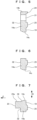
FIG. 5] FIG. 5 is a cross-sectional view taken along line X-X ofFIG. 3 . - [
FIG. 6] FIG. 6 is a cross-sectional view taken along line Y-Y ofFIG. 3 . - [
FIG. 7] FIG. 7 is a cross-sectional view taken along line Z-Z ofFIG. 3 . - [
FIG. 8] FIG. 8 is a perspective view illustrating the front side of the gland of the pipe joint. - [
FIG. 9] FIG. 9 is a perspective view illustrating the back side of the gland of the pipe joint. - [
FIG. 10] FIG. 10 is a schematic diagram illustrating a joining operation of joining pipes using the pipe joint in a groove formed on the ground. - [
FIG. 11] FIG. 11 is a cross-sectional view of the pipe joint illustrating when a first pipe is deflected relative to a second pipe after the pipes are joined. - [
FIG. 12] FIG. 12 is an enlarged view of a part of the cross-sectional view of the pipe joint inFIG. 11 . - [
FIG. 13] FIG. 13 is a cross-sectional view of the pipe joint illustrating when the gland is coupled to the socket by performing sequential tightening when the pipes are joined to each other. - [
FIG. 14] FIG. 14 is an enlarged view of a part of the cross-sectional view of the pipe joint inFIG. 13 . - [
FIG. 15] FIG. 15 is a cross-sectional view of a pipe joint according to a second embodiment of the present invention. - [
FIG. 16] FIG. 16 is a schematic diagram illustrating a state of a joining operation of joining pipes using the pipe joint of standpipes vertically provided along the wall of a building according to a third embodiment of the present invention. - [
FIG. 17] FIG. 17 is a cross-sectional view illustrating a method for joining pipes according to a fourth embodiment of the present invention, in which a gland is coupled to a socket with a spigot deflected relative to the socket. - [
FIG. 18] FIG. 18 is an enlarged view of a part of the cross-sectional view ofFIG. 17 . - [
FIG. 19] FIG. 19 is a cross-sectional view of a pipe joint including a conventional gland. - [
FIG. 20] FIG. 20 is a front view of the gland. - [
FIG. 21] FIG. 21 is a schematic diagram illustrating a state of joining of pipes using the conventional pipe joint in a groove formed on the ground. - Embodiments of the present invention will be described below with reference to the accompanying drawings.
- In a first embodiment, as illustrated in
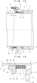
FIG. 1 , apipe joint 1 includes a cast-ironfirst pipe 2 and a cast-ironsecond pipe 4 that are joined to each other. Aspigot 3 provided on one end of thefirst pipe 2 is inserted into asocket 5 provided on one end of thesecond pipe 4. An annular rubber ring 7 (an example of a seal member) is inserted between the outer circumference of thespigot 3 and the inner circumference of thesocket 5. - A
lock ring groove 9 located deeper than therubber ring 7 in thesocket 5 is formed over the inner circumference of thesocket 5. In thelock ring groove 9, a single-split lock ring 10 is provided in the circumferential direction. - The
spigot 3 has a protrudingportion 11 that is formed around the outer circumference of the distal end of thespigot 3 so as to be engaged with thelock ring 10 from the back side of thesocket 5. - A single-
split backup ring 13 is fit onto thespigot 3 in the circumferential direction and is adjacent to thelock ring 10. - The
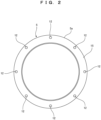
socket 5 has aflange part 5a at the distal end. On theflange part 5a, a plurality of bolt holes 12 are formed. For example, inFIG. 2 , the eightbolt holes 12 are formed on theflange part 5a. Thefirst pipe 2 and thesecond pipe 4 are provided in the horizontal direction, and two of the bolt holes 12 are located on a vertical line. - A
gland 14 for pressing therubber ring 7 into thesocket 5 is fit onto thespigot 3 and faces an opening end face 15 of thesocket 5 from the outside. Thegland 14 has anannular body part 14a that is coupled to thesocket 5 with a plurality of (e.g., seven) T bolts 16 (an example of a fastener) and nuts 17 (an example of a fastener). As illustrated inFIGS. 3 to 9 , thebody part 14a has a plurality of protrudingportions 14b that radially protrude outward around the outer circumference of thebody part 14a. - The
body part 14a is provided with apressing face 19 that presses therubber ring 7, a plurality of bolt insertion holes 21 (an example of a fastener insertion hole) where theT bolts 16 are inserted, a reinforcingmember 23, first projectingportions 24, and a second projectingportion 25. The protrudingportions 14b of thebody part 14a are formed in alignment with the bolt insertion holes 21. - The
gland 14 has anequal interval region 29 and anextended interval region 30. In theequal interval region 29, intervals between the bolt insertion holes 21 in a circumferential direction A are kept at equal intervals S1. In theextended interval region 30, an interval S2 between any adjacent two of the bolt insertion holes 21 is larger than the equal intervals S1. - For example, in
FIGS. 3 and4 , the seven bolt insertion holes 21 are formed on thebody part 14a. An angle of index B1 of the bolt insertion holes 21 is 45° in theequal interval region 29. An angle of index B2 of the bolt insertion holes 21 is 90° in theextended interval region 30. - The reinforcing
member 23 is an arc-shaped member provided on aface 32 on the side opposite to thepressing face 19. The reinforcingmember 23 protrudes from theface 32 in a separating direction C. The separating direction C is a direction that separates thespigot 3 from thesocket 5. The reinforcingmember 23 is provided between the two adjacent bolt insertion holes 21 in theextended interval region 30. The reinforcingmember 23 is located outside aninner circumference 14c of thegland 14 in a radial direction D. - As illustrated in
FIGS. 1 and7 , a taperingportion 34 is formed between theinner circumference 14c of thegland 14 and aninner circumference 23a of the reinforcingmember 23 so as to extend along the length of the reinforcingmember 23. The taperingportion 34 tilts outward in the radial direction D as the taperingportion 34 extends in the separating direction C that separates thespigot 3 from thesocket 5. - As illustrated in
FIG. 4 , from the inside of theextended interval region 30, both endportions 23b of the reinforcingmember 23 extend beyond twostraight lines 36, which radially connect the center of thegland 14 and the centers of both of the bolt insertion holes 21 of theextended interval region 30, and are located in theequal interval region 29. - The first projecting
portions 24 and the second projectingportion 25 are each brought into contact with the opening end face 15 of thesocket 5. In this configuration, the first projectingportions 24 are located outside the bolt insertion holes 21 in the radial direction D of thegland 14. The second projectingportion 25 is located inside the bolt insertion holes 21 in the radial direction D of thegland 14 and is annularly formed around thepressing face 19. As illustrated inFIG. 1 , one end of therubber ring 7 is fit into the second projectingportion 25 of thegland 14 and comes into contact with thepressing face 19. - As illustrated in
FIGS. 1 ,3 , and4 , thegland 14 is coupled to thesocket 5 such that theextended interval region 30 is located directly below thefirst pipe 2. As illustrated inFIG. 10 , thefirst pipe 2 and thesecond pipe 4 are joined to each other in agroove 39 that is formed by digging aground 38. At this point, a bottom 40 of thegroove 39 serves as an obstacle that interferes with a joining operation of thefirst pipe 2 and thesecond pipe 4. Specifically, thegland 14 is coupled to thesocket 5 with the plurality ofT bolts 16 andnuts 17 such that theextended interval region 30 faces the bottom 40 (an example of an obstacle) of thegroove 39. - A method for joining the
first pipe 2 and thesecond pipe 4 with thegland 14 will be described below. - First, the
gland 14, therubber ring 7, and thebackup ring 13 are fit onto thespigot 3 of thefirst pipe 2. Thereafter, thelock ring 10 is attached into thelock ring groove 9 of thesocket 5 of thesecond pipe 4 that has been placed in thegroove 39, and then thelock ring 10 is increased in diameter by using a diameter extending device (not illustrated). - Thereafter, in the
groove 39, thespigot 3 of thefirst pipe 2 is inserted into thesocket 5 of thesecond pipe 4. At this point, thelock ring 10 increased in diameter allows the protrudingportion 11 of thespigot 3 to pass the inner circumference of thelock ring 10 into thesocket 5. - The diameter extending device (not illustrated) is then removed, so that the
lock ring 10 is reduced in diameter and is placed around the outer circumference of thespigot 3. - Subsequently, the
backup ring 13 is moved in a pipe axis direction E and is inserted into thesocket 5, so that thebackup ring 13 is placed next to thelock ring 10. Furthermore, therubber ring 7 is moved in the pipe axis direction E and is placed at the front of the opening end face 15 of thesocket 5. - Thereafter, as illustrated in
FIG. 10 , theT bolt 16 is inserted into thebolt hole 12 of thesocket 5 and thebolt insertion hole 21 of thegland 14 in a state in which theextended interval region 30 of thegland 14 is located directly below thefirst pipe 2. Thenut 17 is then screwed onto theT bolt 16, and then thenut 17 is tightened until the first projectingportion 24 and the second projectingportion 25 of thegland 14 come into contact with the opening end face 15 of thesocket 5. - Thus, as illustrated in
FIG. 1 , thegland 14 is coupled to thesocket 5, and thepressing face 19 of thegland 14 presses in therubber ring 7 between the outer circumference of thespigot 3 and the inner circumference of thesocket 5, so that thefirst pipe 2 is joined to thesecond pipe 4. - According to the method for joining the
pipes FIGS. 3 ,4 , and10 , theextended interval region 30 of thegland 14 is located directly below thefirst pipe 2. Thus, the bolt insertion holes 21 of theextended interval region 30 are not present directly below thefirst pipe 2 but are located at positions separated from a position directly below thefirst pipe 2 in the circumferential direction A of thegland 14. Thus, the distance H between the bolt insertion holes 21 of theextended interval region 30 and the bottom 40 of thegroove 39 is large, achieving high workability even in a small work area between thegland 14 and the bottom 40 of thegroove 39 when thefirst pipe 2 and thesecond pipe 4 are joined to each other. - The
extended interval region 30 of thegland 14 is kept sufficiently rigid by the reinforcingmember 23. Thus, even if a reaction force of therubber ring 7 is applied to thegland 14, theextended interval region 30 of thegland 14 can be prevented from being deflected by the reaction force. Furthermore, since the reinforcingmember 23 is provided, even if a large load is generated between the two bolt insertion holes 21 in theextended interval region 30 when theT bolts 16 are inserted into the bolt insertion holes 21 of theextended interval region 30 of thegland 14 and the bolt holes 12 of thesocket 5 and are tightened with the nuts 17, theextended interval region 30 can be prevented from being deformed or damaged. - As illustrated in
FIG. 7 , the reinforcingmember 23 is located outside theinner circumference 14c of thegland 14 in the radial direction D, and the taperingportion 34 is formed between theinner circumference 14c of thegland 14 and theinner circumference 23a of the reinforcingmember 23. Thus, after thefirst pipe 2 and thesecond pipe 4 are joined to each other in the aforementioned manner, when thefirst pipe 2 is deflected relative to thesecond pipe 4 due to earthquakes or the like, an angle of deflection α before thefirst pipe 2 comes into contact with the reinforcingmember 23 of thegland 14 is larger than an angle of deflection when theinner circumference 23a of the reinforcingmember 23 is located at the same position as theinner circumference 14c of thegland 14 in the radial direction D. This reduces a load applied to thegland 14 when thefirst pipe 2 is deflected relative to thesecond pipe 4. - In the method for joining the
first pipe 2 and thesecond pipe 4, when theT bolts 16 are inserted into the bolt holes 12 of thesocket 5 and the bolt insertion holes 21 of thegland 14 to couple thegland 14 to thesocket 5, as illustrated inFIG. 13 , so-called "sequential tightening" may be performed, that is, theT bolt 16 at the uppermost position and thenut 17 are tightened first, and then theT bolts 16 at lower positions and the nuts 17 are sequentially tightened. As described above, sequential tightening is performed on theT bolts 16 and the nuts 17, so that even if thegland 14 tilts relative to thefirst pipe 2, a tilt angle β before the reinforcingmember 23 of thegland 14 comes into contact with thefirst pipe 2 is larger than a tilt angle when theinner circumference 23a of the reinforcingmember 23 is located at the same position as theinner circumference 14c of thegland 14 in the radial direction D. This facilitates the operations of sequential tightening on theT bolts 16 and the nuts 17 and coupling between thegland 14 to thesocket 5. - In a second embodiment, as illustrated in
FIG. 15 , a reinforcingmember 23 is located outside aninner circumference 14c of agland 14 in a radial direction D.A step portion 50 is formed between theinner circumference 14c of thegland 14 and aninner circumference 23a of the reinforcingmember 23 so as to extend along the length of the reinforcingmember 23. Thestep portion 50 has a step face parallel to the radial direction D. - With this configuration, as in the first embodiment, if a
first pipe 2 is deflected relative to asecond pipe 4 due to earthquakes or the like after thefirst pipe 2 and thesecond pipe 4 are joined to each other, an angle of deflection α (seeFIG. 11 ) before thefirst pipe 2 comes into contact with the reinforcingmember 23 of thegland 14 is larger than an angle of deflection when theinner circumference 23a of the reinforcingmember 23 is located at the same position as theinner circumference 14c of thegland 14 in the radial direction D. - Moreover, in a method for joining the
first pipe 2 and thesecond pipe 4, whenT bolts 16 are inserted into bolt holes 12 of asocket 5 and bolt insertion holes 21 of thegland 14 to couple thegland 14 to thesocket 5, even if thegland 14 tilts relative to thefirst pipe 2 due to sequential tightening performed on theT bolts 16 andnuts 17, a tilt angle β (seeFIG. 13 ) before the reinforcingmember 23 of thegland 14 comes into contact with thefirst pipe 2 is larger than a tilt angle when theinner circumference 23a of the reinforcingmember 23 is located at the same position as theinner circumference 14c of thegland 14 in the radial direction D. - In the first embodiment, as illustrated in
FIG. 10 , the bottom 40 of thegroove 39 serves as an obstacle that interferes with a joining operation of thefirst pipe 2 and thesecond pipe 4. Moreover, thegland 14 is coupled to thesocket 5 with the plurality ofT bolts 16 andnuts 17 such that theextended interval region 30 faces the bottom 40 of thegroove 39. However, the obstacle is not limited to the bottom 40 of thegroove 39. - For example, in a third embodiment described below, a
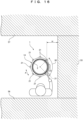
first pipe 2 and asecond pipe 4 are, for example, vertically provided standpipes as illustrated inFIG. 16 and are surrounded by buildingwalls 55 to 57 on three sides. In this case, thewall 55 closest to thefirst pipe 2 and thesecond pipe 4 serves as an obstacle that interferes with a joining operation of thefirst pipe 2 and thesecond pipe 4. Moreover, agland 14 is coupled to asocket 5 with a plurality ofT bolts 16 andnuts 17 such that anextended interval region 30 faces thewall 55. - With this configuration, when the
first pipe 2 and thesecond pipe 4 are joined to each other, theextended interval region 30 of thegland 14 faces thewall 55. Thus, two bolt insertion holes 21 of theextended interval region 30 are located at positions separated from a position closest to thewall 55 in a circumferential direction A of thegland 14. Thus, a distance H between the bolt insertion holes 21 of theextended interval region 30 and thewall 55 is larger than a distance between the bolt insertion hole of the gland and the wall if the gland only has anequal interval region 29 without theextended interval region 30. This can improve workability even if thefirst pipe 2 and thesecond pipe 4 are joined to each other in a small work area. - In the first embodiment, when the
first pipe 2 and thesecond pipe 4 are joined to each other as illustrated inFIG. 1 , theT bolts 16 are inserted into the bolt holes 12 of thesocket 5 and the bolt insertion holes 21 of thegland 14 with thespigot 3 kept in line with thesocket 5, and then the nuts 17 are tightened, so that thegland 14 in an upright position is coupled to thesocket 5. However, the present invention is not limited to the joining method. For example, in a fourth embodiment described below, aspigot 3 is inserted into asocket 5, and then thespigot 3 is diagonally deflected relative to thesocket 5 as illustrated inFIGS. 17 and 18 . In this state, agland 14 may be coupled to thesocket 5 by insertingT bolts 16 into bolt holes 12 of thesocket 5 and bolt insertion holes 21 of agland 14 and tightening nuts 17. - In the fourth embodiment, as illustrated in
FIG. 18 , thegland 14 with a taperingportion 34 is used. Agland 14 with a step portion 50 (seeFIG. 15 ) may be used instead. - In the first to fourth embodiments, as illustrated in
FIGS. 3 and4 , the seven bolt insertion holes 21 are formed on thegland 14. The number of bolt insertion holes 21 is not limited to seven and may be determined by, for example, subtracting 1 from a multiple of 4 (11 or 15). - As illustrated in
FIG. 4 , in the first to fourth embodiments, the bothend portions 23b of the reinforcingmember 23 extend beyond the twostraight lines 36 from the inside of theextended interval region 30 and are located in theequal interval region 29. However, the bothend portions 23b of the reinforcingmember 23 may be formed between the twostraight lines 36 without extending beyond the twostraight lines 36. - The
gland 14 has the taperingportion 34 in the first embodiment as illustrated inFIG. 1 , and thegland 14 has thestep portion 50 in the second embodiment as illustrated inFIG. 15 . Theinner circumference 14c of thegland 14 and theinner circumference 23a of the reinforcingmember 23 may have the same diameter without forming the taperingportion 34 or thestep portion 50, and theinner circumference 14c of thegland 14 and theinner circumference 23a of the reinforcingmember 23 may be flush with each other. However, the formation of the taperingportion 34 or thestep portion 50 can advantageously increase an angle of deflection α (seeFIG. 11 ) between thefirst pipe 2 and thesecond pipe 4 and a tilt angle β (seeFIG. 13 ) of thegland 14 as compared with the case where the taperingportion 34 or thestep portion 50 is not formed.
Claims (8)
- A gland provided for a pipe joint in which a spigot is inserted into a socket, anda seal member is inserted between an outer circumference of the spigot and an inner circumference of the socket,wherein the gland is fit onto the spigot so as to face an opening end face of the socket from outside and is coupled to the socket with a plurality of fasteners so as to press the seal member into the socket,the gland has a pressing face for pressing the seal member, a plurality of fastener insertion holes where the fasteners are inserted, an equal interval region in which intervals between the fastener insertion holes in a circumferential direction are kept at equal intervals, and an extended interval region in which an interval between any adjacent two of the fastener insertion holes is larger than the equal intervals, andthe extended interval region includes a reinforcing member.
- The gland according to claim 1, wherein the extended interval region faces an obstacle that interferes with a joining operation for the pipes to each other.
- The gland according to claim 1 or 2, wherein the reinforcing member is provided on a side opposite to the pressing face, protrudes from the side opposite to the pressing face in a separating direction that separates the spigot from the socket, and is located outside an inner circumference of the gland in a radial direction, and
a step portion is formed between the inner circumference of the gland and an inner circumference of the reinforcing member. - The gland according to claim 1 or 2, wherein the reinforcing member is provided on a side opposite to the pressing face, protrudes from the side opposite to the pressing face in a separating direction that separates the spigot from the socket, and is located outside an inner circumference of the gland in a radial direction, anda tapering portion is formed between the inner circumference of the gland and an inner circumference of the reinforcing member, andthe tapering portion tilts outward in the radial direction as the tapering portion extends in the separating direction that separates the spigot from the socket.
- The gland according to claim 1, wherein the reinforcing member is provided between the two adjacent fastener insertion holes in the extended interval region.
- A pipe joint comprising the gland according to claim 1, wherein a spigot is inserted into a socket,a seal member is inserted between the outer circumference of the spigot and the inner circumference of the socket,the gland is fit onto the spigot so as to face the opening end face of the socket from the outside and is coupled to the socket with the plurality of fasteners while the extended interval region faces an obstacle that interferes with a joining operation of the pipes,the gland has a pressing surface in contact with the seal member, andthe fasteners are inserted into the fastener insertion holes of the gland.
- A method for joining pipes using the gland according to claim 1, wherein the spigot is inserted into the socket, and the gland is coupled to the socket and the seal member is inserted between the outer circumference of the spigot and the inner circumference of the socket by inserting the fasteners into the fastener insertion holes of the gland and tightening the fasteners in a state in which the extended interval region of the gland faces an obstacle that interferes with a joining operation of the pipes.
- The method for joining pipes according to claim 7, wherein the spigot is inserted into the socket, and the gland is coupled to the socket by inserting the fasteners into the fastener insertion holes of the gland and tightening the fasteners in a state in which the spigot is diagonally deflected relative to the socket.
Applications Claiming Priority (2)
| Application Number | Priority Date | Filing Date | Title |
|---|---|---|---|
| JP2021143577A JP7649720B2 (en) | 2021-09-03 | 2021-09-03 | Press ring, pipe joint, and pipe joining method |
| PCT/JP2022/032945 WO2023033106A1 (en) | 2021-09-03 | 2022-09-01 | Push ring, pipe joint, and method for joining pipes |
Publications (2)
| Publication Number | Publication Date |
|---|---|
| EP4382792A1 true EP4382792A1 (en) | 2024-06-12 |
| EP4382792A4 EP4382792A4 (en) | 2025-04-30 |
Family
ID=85412361
Family Applications (1)
| Application Number | Title | Priority Date | Filing Date |
|---|---|---|---|
| EP22864688.1A Pending EP4382792A4 (en) | 2021-09-03 | 2022-09-01 | Pressure ring, pipe joint and method for joining pipes |
Country Status (6)
| Country | Link |
|---|---|
| US (1) | US20250180146A1 (en) |
| EP (1) | EP4382792A4 (en) |
| JP (1) | JP7649720B2 (en) |
| CN (1) | CN118234988A (en) |
| CA (1) | CA3230095A1 (en) |
| WO (1) | WO2023033106A1 (en) |
Families Citing this family (1)
| Publication number | Priority date | Publication date | Assignee | Title |
|---|---|---|---|---|
| USD1108590S1 (en) * | 2023-09-06 | 2026-01-06 | Advanced Drainage Systems, Inc. | Reducing flat top drainage structure |
Family Cites Families (22)
| Publication number | Priority date | Publication date | Assignee | Title |
|---|---|---|---|---|
| US689624A (en) * | 1901-02-06 | 1901-12-24 | Ella M Cozens | Pipe-joint. |
| US940098A (en) * | 1908-02-29 | 1909-11-16 | Nat Water Main Cleaning Co | Device for joining parts of conduits. |
| US2105022A (en) * | 1934-02-09 | 1938-01-11 | Stanton Ironworks Co Ltd | Pipe joint |
| US2108848A (en) * | 1934-06-30 | 1938-02-22 | Inner Tite Clamp Corp | Pipe joint |
| US2679410A (en) * | 1950-10-07 | 1954-05-25 | Southern Pipe & Casing Co | Bell and spigot joint and sealing clamp |
| US3469852A (en) * | 1965-10-23 | 1969-09-30 | Smith Blair Inc | Leak clamp for bell and spigot pipe joint |
| US3473573A (en) * | 1966-10-06 | 1969-10-21 | Baker Mfg Co | Well cap and seal therefor |
| JPS5453318A (en) * | 1977-10-04 | 1979-04-26 | Kubota Ltd | Escape-out preventing device for pipe joint |
| FR2441121A1 (en) * | 1978-11-13 | 1980-06-06 | Pont A Mousson | IMPROVEMENTS ON INTERLOCKED JOINTS |
| US4411312A (en) * | 1980-08-26 | 1983-10-25 | Hewing Manufacturing Corporation | Water-tight conduit well cap |
| US5129681A (en) * | 1990-11-30 | 1992-07-14 | Yano Giken Co., Ltd. | Method of rendering laid pipeline flexible and pipe joint suited for executing this method |
| FR2714143B1 (en) * | 1993-12-22 | 1996-03-15 | Gerard Chevrier | Connection device for high pressure pipes and tubes. |
| JPH10122456A (en) * | 1996-10-24 | 1998-05-15 | Kubota Corp | Seismic structure of pipe fittings |
| JP3517381B2 (en) | 2000-03-03 | 2004-04-12 | 株式会社栗本鐵工所 | Carriage for sheath insertion method |
| GB2377736A (en) * | 2001-07-18 | 2003-01-22 | Saint Gobain Pipelines Plc | A pipe coupling |
| JP4248213B2 (en) | 2001-10-30 | 2009-04-02 | 株式会社クボタ | Seismic pipe joints in the sheath pipe propulsion method |
| JP5451275B2 (en) | 2009-05-13 | 2014-03-26 | 株式会社クボタ | Pipe fitting |
| KR20100094048A (en) * | 2009-02-18 | 2010-08-26 | (주) 삼정디씨피 | Flange type mechanical joint |
| JP5665801B2 (en) | 2012-06-25 | 2015-02-04 | 株式会社クボタ | Pressers and fittings and valves |
| CN105065811B (en) * | 2012-06-25 | 2017-05-24 | 株式会社久保田 | Pressing ring, coupling, and valve |
| GB201312284D0 (en) * | 2013-07-09 | 2013-08-21 | Crane Ltd | Pipe connection |
| US20250224054A1 (en) * | 2021-09-03 | 2025-07-10 | Kubota Corporation | Gland, pipe joint, and method for joining pipes |
-
2021
- 2021-09-03 JP JP2021143577A patent/JP7649720B2/en active Active
-
2022
- 2022-09-01 EP EP22864688.1A patent/EP4382792A4/en active Pending
- 2022-09-01 CN CN202280070448.3A patent/CN118234988A/en active Pending
- 2022-09-01 CA CA3230095A patent/CA3230095A1/en active Pending
- 2022-09-01 US US18/688,175 patent/US20250180146A1/en active Pending
- 2022-09-01 WO PCT/JP2022/032945 patent/WO2023033106A1/en not_active Ceased
Also Published As
| Publication number | Publication date |
|---|---|
| EP4382792A4 (en) | 2025-04-30 |
| WO2023033106A1 (en) | 2023-03-09 |
| TW202319672A (en) | 2023-05-16 |
| US20250180146A1 (en) | 2025-06-05 |
| CN118234988A (en) | 2024-06-21 |
| JP7649720B2 (en) | 2025-03-21 |
| CA3230095A1 (en) | 2023-03-09 |
| JP2023037051A (en) | 2023-03-15 |
Similar Documents
| Publication | Publication Date | Title |
|---|---|---|
| EP4043771B1 (en) | Pipe joint | |
| US20250180146A1 (en) | Gland, pipe joint, and method for joining pipes | |
| JP3359510B2 (en) | Seismic structure of pipe joints | |
| EP4382791A1 (en) | Pressing ring, pipe joint, and method for joining pipes | |
| TWI924932B (en) | Pressing ring, pipe joint and pipe connecting method | |
| JP3204843B2 (en) | Captive fittings | |
| JP2024009299A (en) | Pipe fitting separation prevention structure | |
| JP7702313B2 (en) | Press ring, pipe joint, and pipe joining method | |
| JP3939100B2 (en) | Earthquake resistant joints and earthquake resistant pipelines | |
| JP4204337B2 (en) | Pipe fitting method | |
| JPH0972470A (en) | Expansion fluid pipe for coupling fluid pipe | |
| JPH025176Y2 (en) | ||
| TW202316053A (en) | Pipe joint, pressing ring and pipe connecting method | |
| JPH0443670Y2 (en) | ||
| JP7742331B2 (en) | Pipe fitting and steel pipe connection method | |
| JPH09250668A (en) | Captive fittings | |
| JPH11108267A (en) | Pipe fittings | |
| JPH07280152A (en) | Pipe separation prevention fitting for union nut fitting | |
| JP3268110B2 (en) | Segment joint structure | |
| JP2007056587A (en) | Pile connection structure | |
| JP2000065259A (en) | Conduit fittings | |
| JP2589790B2 (en) | Segment joint structure | |
| JP2547707B2 (en) | Pipe separation prevention device for expansion and contraction flexible pipe joints | |
| JPH0619904Y2 (en) | Pipe fitting | |
| JP2001032973A (en) | Pipe fitting structure |
Legal Events
| Date | Code | Title | Description |
|---|---|---|---|
| STAA | Information on the status of an ep patent application or granted ep patent |
Free format text: STATUS: THE INTERNATIONAL PUBLICATION HAS BEEN MADE |
|
| PUAI | Public reference made under article 153(3) epc to a published international application that has entered the european phase |
Free format text: ORIGINAL CODE: 0009012 |
|
| STAA | Information on the status of an ep patent application or granted ep patent |
Free format text: STATUS: REQUEST FOR EXAMINATION WAS MADE |
|
| 17P | Request for examination filed |
Effective date: 20240306 |
|
| AK | Designated contracting states |
Kind code of ref document: A1 Designated state(s): AL AT BE BG CH CY CZ DE DK EE ES FI FR GB GR HR HU IE IS IT LI LT LU LV MC MK MT NL NO PL PT RO RS SE SI SK SM TR |
|
| RAP3 | Party data changed (applicant data changed or rights of an application transferred) |
Owner name: KUBOTA CORPORATION |
|
| DAV | Request for validation of the european patent (deleted) | ||
| DAX | Request for extension of the european patent (deleted) | ||
| A4 | Supplementary search report drawn up and despatched |
Effective date: 20250328 |
|
| RIC1 | Information provided on ipc code assigned before grant |
Ipc: F16L 21/08 20060101ALI20250324BHEP Ipc: F16L 21/04 20060101AFI20250324BHEP |