EP4382781A1 - Low torque valve - Google Patents
Low torque valve Download PDFInfo
- Publication number
- EP4382781A1 EP4382781A1 EP23213592.1A EP23213592A EP4382781A1 EP 4382781 A1 EP4382781 A1 EP 4382781A1 EP 23213592 A EP23213592 A EP 23213592A EP 4382781 A1 EP4382781 A1 EP 4382781A1
- Authority
- EP
- European Patent Office
- Prior art keywords
- valve body
- tapered
- tapered valve
- housing
- flow passage
- Prior art date
- Legal status (The legal status is an assumption and is not a legal conclusion. Google has not performed a legal analysis and makes no representation as to the accuracy of the status listed.)
- Granted
Links
Images




Classifications
-
- F—MECHANICAL ENGINEERING; LIGHTING; HEATING; WEAPONS; BLASTING
- F16—ENGINEERING ELEMENTS AND UNITS; GENERAL MEASURES FOR PRODUCING AND MAINTAINING EFFECTIVE FUNCTIONING OF MACHINES OR INSTALLATIONS; THERMAL INSULATION IN GENERAL
- F16K—VALVES; TAPS; COCKS; ACTUATING-FLOATS; DEVICES FOR VENTING OR AERATING
- F16K5/00—Plug valves; Taps or cocks comprising only cut-off apparatus having at least one of the sealing faces shaped as a more or less complete surface of a solid of revolution, the opening and closing movement being predominantly rotary
- F16K5/02—Plug valves; Taps or cocks comprising only cut-off apparatus having at least one of the sealing faces shaped as a more or less complete surface of a solid of revolution, the opening and closing movement being predominantly rotary with plugs having conical surfaces; Packings therefor
- F16K5/0242—Spindles and actuating means
-
- F—MECHANICAL ENGINEERING; LIGHTING; HEATING; WEAPONS; BLASTING
- F16—ENGINEERING ELEMENTS AND UNITS; GENERAL MEASURES FOR PRODUCING AND MAINTAINING EFFECTIVE FUNCTIONING OF MACHINES OR INSTALLATIONS; THERMAL INSULATION IN GENERAL
- F16K—VALVES; TAPS; COCKS; ACTUATING-FLOATS; DEVICES FOR VENTING OR AERATING
- F16K5/00—Plug valves; Taps or cocks comprising only cut-off apparatus having at least one of the sealing faces shaped as a more or less complete surface of a solid of revolution, the opening and closing movement being predominantly rotary
- F16K5/08—Details
- F16K5/14—Special arrangements for separating the sealing faces or for pressing them together
- F16K5/16—Special arrangements for separating the sealing faces or for pressing them together for plugs with conical surfaces
- F16K5/162—Special arrangements for separating the sealing faces or for pressing them together for plugs with conical surfaces with the plugs or parts of the plugs mechanically pressing the seal against the housing
- F16K5/163—Special arrangements for separating the sealing faces or for pressing them together for plugs with conical surfaces with the plugs or parts of the plugs mechanically pressing the seal against the housing adjustable in height
-
- F—MECHANICAL ENGINEERING; LIGHTING; HEATING; WEAPONS; BLASTING
- F16—ENGINEERING ELEMENTS AND UNITS; GENERAL MEASURES FOR PRODUCING AND MAINTAINING EFFECTIVE FUNCTIONING OF MACHINES OR INSTALLATIONS; THERMAL INSULATION IN GENERAL
- F16K—VALVES; TAPS; COCKS; ACTUATING-FLOATS; DEVICES FOR VENTING OR AERATING
- F16K11/00—Multiple-way valves, e.g. mixing valves; Pipe fittings incorporating such valves
- F16K11/02—Multiple-way valves, e.g. mixing valves; Pipe fittings incorporating such valves with all movable sealing faces moving as one unit
- F16K11/08—Multiple-way valves, e.g. mixing valves; Pipe fittings incorporating such valves with all movable sealing faces moving as one unit comprising only taps or cocks
- F16K11/083—Multiple-way valves, e.g. mixing valves; Pipe fittings incorporating such valves with all movable sealing faces moving as one unit comprising only taps or cocks with tapered plug
- F16K11/0833—Multiple-way valves, e.g. mixing valves; Pipe fittings incorporating such valves with all movable sealing faces moving as one unit comprising only taps or cocks with tapered plug having all the connecting conduits situated in a single plane perpendicular to the axis of the plug
-
- F—MECHANICAL ENGINEERING; LIGHTING; HEATING; WEAPONS; BLASTING
- F16—ENGINEERING ELEMENTS AND UNITS; GENERAL MEASURES FOR PRODUCING AND MAINTAINING EFFECTIVE FUNCTIONING OF MACHINES OR INSTALLATIONS; THERMAL INSULATION IN GENERAL
- F16K—VALVES; TAPS; COCKS; ACTUATING-FLOATS; DEVICES FOR VENTING OR AERATING
- F16K27/00—Construction of housing; Use of materials therefor
- F16K27/06—Construction of housing; Use of materials therefor of taps or cocks
- F16K27/062—Construction of housing; Use of materials therefor of taps or cocks with conical plugs
-
- F—MECHANICAL ENGINEERING; LIGHTING; HEATING; WEAPONS; BLASTING
- F16—ENGINEERING ELEMENTS AND UNITS; GENERAL MEASURES FOR PRODUCING AND MAINTAINING EFFECTIVE FUNCTIONING OF MACHINES OR INSTALLATIONS; THERMAL INSULATION IN GENERAL
- F16K—VALVES; TAPS; COCKS; ACTUATING-FLOATS; DEVICES FOR VENTING OR AERATING
- F16K5/00—Plug valves; Taps or cocks comprising only cut-off apparatus having at least one of the sealing faces shaped as a more or less complete surface of a solid of revolution, the opening and closing movement being predominantly rotary
- F16K5/02—Plug valves; Taps or cocks comprising only cut-off apparatus having at least one of the sealing faces shaped as a more or less complete surface of a solid of revolution, the opening and closing movement being predominantly rotary with plugs having conical surfaces; Packings therefor
- F16K5/0257—Packings
- F16K5/0271—Packings between housing and plug
-
- F—MECHANICAL ENGINEERING; LIGHTING; HEATING; WEAPONS; BLASTING
- F16—ENGINEERING ELEMENTS AND UNITS; GENERAL MEASURES FOR PRODUCING AND MAINTAINING EFFECTIVE FUNCTIONING OF MACHINES OR INSTALLATIONS; THERMAL INSULATION IN GENERAL
- F16K—VALVES; TAPS; COCKS; ACTUATING-FLOATS; DEVICES FOR VENTING OR AERATING
- F16K5/00—Plug valves; Taps or cocks comprising only cut-off apparatus having at least one of the sealing faces shaped as a more or less complete surface of a solid of revolution, the opening and closing movement being predominantly rotary
- F16K5/08—Details
- F16K5/14—Special arrangements for separating the sealing faces or for pressing them together
- F16K5/16—Special arrangements for separating the sealing faces or for pressing them together for plugs with conical surfaces
- F16K5/162—Special arrangements for separating the sealing faces or for pressing them together for plugs with conical surfaces with the plugs or parts of the plugs mechanically pressing the seal against the housing
Definitions
- the present invention relates to rotary valves, and in particular, multi-port rotary valves for controlling coolant flow in battery electric vehicles and for other applications.
- Battery electric vehicles rely on complex cooling circuits to ensure the vehicle batteries, power electronics, and the electric motor are operating within an optimal temperature range.
- These cooling circuits typically include several multi-port rotary valves to help meet the cooling demands of these and other vehicle systems.
- existing battery electric vehicles include one or more five-port or eight-port rotary valves that direct the flow of coolant to a corresponding number of different routing paths of the vehicle cooling system.
- Multi-port rotary valves generally include a valve body that is rotated within a flow passage about an axis that is normal to a flow stream.
- the valve body can include a number of possible geometries, including tapered and cylindrical plugs, with each such plug defining one or more flow passages therethrough.
- the valve body can be rotated in the clockwise and/or counter-clockwise directions in response to a motor actuator to thereby open or close the rotary valve.
- the sealing ability (leakage rate) of a rotary valve having a tapered valve body is proportional to the torque demand on the motor actuator.
- high power motor actuators are ordinarily required.
- a low torque rotary valve for a vehicle cooling system includes a tapered valve body that can be lifted during rotation and thereafter seated after being rotated the desired amount.
- An axial surface of the tapered valve body is in sliding contact with an axial surface of a valve housing or a rotatable disk.
- one or more ramped projections cause the tapered valve body to displace axially within the valve housing. Sealing members are uncompressed during rotation of the tapered valve body, and a lower torque demand is required, thereby allowing for a smaller and less costly motor actuator.
- the rotary valve includes a rotatable disk having a ramped projection for engaging the tapered valve body.
- An overrunning clutch is joined to or integral with a lower portion of the tapered valve body to permit rotation of the tapered valve body in only a single direction.
- the rotatable disk pushes tangentially on the upper surface of the rotary valve and rotates the valve body in the first direction.
- the rotatable disk rotates in the opposite direction.
- the tapered valve body is prevented from rotating in this opposite direction by the overrunning clutch and is instead driven axially within a valve housing by operation of the ramped projection to compress the sealing members against the interior of the valve housing.
- the rotatable disk and the overrunning clutch are omitted, and the rotary valve instead includes inter-engaging camming surfaces on an axial surface of the tapered valve body and an axial surface of the valve housing.
- the tapered valve body of this embodiment is bi-directional and is driven by an input shaft extending through the valve housing. Rotation of the tapered valve body within the valve housing causes the camming surfaces to slide over each other and axially displace the tapered valve body against a spring element, such that sealing members between the tapered valve body and the valve housing are at least partially uncompressed during rotation of the tapered valve body within the valve housing.
- the tapered valve body includes at least one flow passage extending transverse to a rotational axis of the tapered valve body.
- the tapered valve body can include a single flow passage in some embodiments, while in other embodiments the tapered valve body includes two or more flow passages.
- the flow passage or passages can be straight, "L" shaped, "T” shaped, or "X” shaped for connecting two, three, or four ports in the valve housing.
- the sealing members can include a sealing element, for example an o-ring, surrounding the entrance/exit of each flow passage.
- the spring element can include a helical compression spring positioned between an axial surface of the tapered valve body and a portion of the valve housing.
- the rotary valve of these and other embodiments decouples the proportional relationship between the sealing ability of the rotary valve and the associated torque demand.
- the rotary valve provides low resistance to rotation from state to state, simplifies actuator demand, and maintains a strong seal to prevent coolant leakage.
- the rotary valve can achieve a longer service life when compared to existing, high-torque rotary valves, and the rotary valve can be readily adapted for a wide variety of multi-port configurations for cooling circuits and other systems.
- the rotary valve 10 includes a valve housing 12 containing a tapered valve body 14, a rotatable disk 16, and a rotatable clutch 18.
- the tapered valve body 16 is lifted by action of a spring 20 during rotation of the rotatable disk 16 in a first direction and thereafter seated after the rotatable disk 16 is counter-rotated.
- the rotatable clutch 18 prevents the valve body 14 from rotating in the opposite direction. Because the tapered valve body 14 is lifted during rotation, the sealing members 22, 24 are uncompressed, and a lower torque demand is required, thereby allowing for a smaller and less costly motor actuator.
- Each such feature of the rotary valve 10 is discussed below.
- the valve housing 12 generally includes an upper housing 26 and a lower housing 28 that collectively define an enclosure for the tapered valve body 14, the rotatable disk 16, the rotatable clutch 18, and the spring 20.
- the lower housing 28 includes a tapered sidewall 30 extending upwardly and outwardly from a lower end-wall 32.
- the tapered sidewall 30 includes at least one inlet port 34 and at least one outlet port 36.
- the inlet port 34 and the outlet port 36 each define a flow passage that is generally orthogonal to the rotational axis 38 of the tapered valve body 14. While two ports are shown in the Figures 1-2 , in other embodiments a greater number of inlet ports and/or outlet ports can be used in other embodiments. In still other embodiments, the ports are bi-directional, such that any given port can function as both an inlet port and an outlet port, dependent on the orientation of the tapered valve body 14 within the valve housing 12.
- the upper housing 26 includes a cylindrical sidewall 40 extending downward from an upper end-wall 42.
- the upper and lower housing 26, 28 include respective flanges 44, 46 that are joined to each other according to any suitable method to provide a liquid-tight seal about the periphery of the valve housing 12.
- the upper flange 44 can be ultrasonically welded to the lower flange 46, while in other embodiments the upper flange 44 is secured to the lower flange 46 via a plurality of fasteners that extend into aligned openings in the respective flanges 44, 46.
- the upper end-wall 42 includes an outer diameter that is greater than the outer diameter of the lower end-wall 32.
- the upper end-wall 42 includes a central aperture 48 for a stem 50 extending upwardly from the rotatable disk 16.
- the rotatable disk 16 includes a head 52 fixedly joined to the aforementioned stem 50.
- the stem 50 is adapted to transfer torque from a motor actuator to the head 52 of the rotatable disk 16.
- the rotatable disk 16 includes an axis of rotation that is concentric with the rotational axis 38 of the tapered valve body 14.
- the head 52 is disk-shaped and includes a lower surface 54 having at least one ramped projection 56.
- the ramped projection 56 makes sliding contact with a corresponding ramped projection 60 on the tapered valve body 14 while rotating to impart axial motion to the tapered valve body 14.
- Each ramped projection includes a uniform pitch, such that the ramped projection gradually increases from a minimum height to a maximum height.
- each projection spans approximately 360/n degrees in the circumferential direction.
- each ramped projection spans approximately 180 degrees in the circumferential direction.
- each ramped projection spans approximately 120 degrees in the circumferential direction.
- each ramped projection spans approximately 90 degrees. Still greater number of ramped projections can be used in other embodiments.
- the ramped projections are asymmetrically disposed about the exterior of the rotatable disk 16, such that at least two of the ramped projection sweep through a different angular range, e.g., one projection spanning 270 degrees and the other projection spanning 90 degrees.
- the tapered valve body 14 includes a sloped outer surface 64.
- the sloped outer surface 64 is V-shaped and increases in diameter in the vertical direction when viewed from the side (i.e., the diameter of the sloped outer surface 64 increases along the height of the tapered valve body 14).
- the tapered valve body 14 includes at least one flow-passage 66 therethrough, the flow passage 66 being transverse to the rotational axis 38 of the tapered valve body 14. While a single flow-passage 66 is shown in Figures 1-2 , in other embodiments the tapered valve body 14 includes two, three, or more flow passages.
- the tapered valve body 14 includes an upper surface having at least one ramped projection 60.
- the ramped projection(s) 60 of the tapered valve body 14 make sliding contact with ramped projection(s) 56 of the rotatable disk 16.
- Each ramped projection 60 of the tapered valve body 14 includes a uniform pitch, such that the ramped projection gradually increases from a minimum height to a maximum height.
- the pitch is approximately 15 degrees in the illustrated embodiment but can be greater than or less than 15 degrees in other embodiments.
- the tapered valve body 14 can include n-number of ramped projections that span 360/n degrees in the circumferential direction.
- the ramped projections of the tapered valve body 14 can be asymmetrically disposed, such that at least two of the ramped projection sweep through a different angular range, e.g., one projection spanning 270 degrees and the other projection spanning 90 degrees.
- the rotary valve 10 includes a rotatable clutch 18 and a spring element 20.
- the spring element 20 is adapted to bias the valve body 14 upwardly against the rotatable disk 16.
- the rotatable disk 16 is constrained in the vertical direction but has rotational freedom when driven by a rotary actuator.
- the spring element 20 is a helical compression spring in the illustrated embodiment but can include other spring elements in other embodiments.
- the rotatable clutch 18 is coupled to the lower extent of the tapered valve body 14 and is adapted to permit rotation of the tapered valve body 14 in only a single direction (e.g., clockwise or counter-clockwise).
- the present invention is not limited to a particular rotatable clutch (also referred to as an overrunning clutch). Examples include a ratchet clutch, a sprag clutch, a compliant clutch, and a roller clutch. Still other rotatable clutches can be used in other embodiments.
- the tapered valve body 14 is lifted and rotated during rotation of the rotatable disk 16 in a first direction and thereafter seated after the rotatable disk 16 is counter-rotated.
- the sealing members 22, 24 are initially compressed between the tapered valve body 14 and the tapered sidewall 30.
- Rotation of the rotatable disk 16 in the counter-clockwise direction causes the tapered valve body 14 to travel vertically by action of the compression spring 20.
- Figure 2 depicts the seals 22, 24 in the uncompressed state.
- the valve body 14 rotates in unison with the rotatable disk 16 in the counter-clockwise direction, as the rotatable disk 16 remains frictionally engaged with the tapered valve body 14.
- the rotatable disk 16 After the tapered valve body 14 is rotated by the desired amount, the rotatable disk 16 reverses direction.
- the ramped projection 56 of the rotatable disk 16 drives the valve body 14 downward, against the spring 20, thereby compressing the seals 22, 24 surrounding each port 34, 36, while the rotatable clutch 18 prevents the rotation of the tapered valve body 14 in the reverse direction.
- a multi-port rotary valve in accordance with a second embodiment is illustrated and generally designated 70.
- the rotary valve 70 of Figures 3-6 is structurally and functionally similar to the rotary valve 10 of Figures 1-2 , except that ramped projections of the rotatable disk are integrally formed with the upper housing.
- the rotatable clutch is also omitted, as this embodiment allows for bi-directional rotation of the valve body.
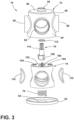
- the rotary valve 70 of Figures 3-6 includes a valve housing 72, a tapered valve body 74, an input shaft 76, and a spring element 78.
- the valve housing 72 includes an upper housing 80 and a lower housing 82 that cooperate to define an enclosure for the tapered valve body 74.
- the upper housing 80 includes a tapered sidewall 84 extending downwardly and outwardly from an upper end-wall 86.
- the tapered sidewall 84 includes four ports 88 that each define a flow passage that is generally orthogonal to the rotational axis 90 of the tapered valve body 74. While four ports 88 are shown in the Figures 3-6 , in other embodiments the valve housing 72 can include a different number of ports.
- the lower housing 82 includes a cover having a spring seat 92 for the spring element 78.
- the upper end-wall 86 includes a central aperture 94 for the input shaft 76, shown in Figure 3 .
- the upper and lower housings 80, 82 are joined to each other according to any suitable method. Because the upper housing 80 is tapered, the upper end-wall 86 includes an outer diameter that is less than the outer diameter of the lower housing 82.
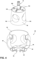
- FIG. 4 An inverted view of interior of the upper housing 80 is shown in Figure 4 .
- the upper housing 80 includes a repeating series of ramped projections 96-optionally configured as an undulating camming surface-that extend around the circumference of the upper-end wall 86.
- the tapered valve body 74 and the input shaft 76 are also shown in Figure 4 .
- the tapered valve body 74 includes a sloped outer surface 98.
- the valve body 74 is frustoconical and narrows in the vertical direction (i.e., the diameter of the sloped outer surface 98 decreases along the height of the valve body 74).
- the tapered valve body 74 includes at least one flow-passage 100 therethrough, the at least one flow passage 100 being transverse to the rotational axis 90 of the tapered valve body 74. While the tapered valve body 74 includes a "X" shaped channel for connecting four ports 88, the tapered valve body 74 can alternatively include a single “L” shaped channel for connecting two ports, a single “T” shaped channel for connecting three ports, or two “L” shaped channels for connecting four ports, each being transverse to (and optionally intersecting) the rotational axis 90 of the tapered valve body 74. Other configurations are possible in other embodiments.
- the upper surface 102 of the valve body 74 also includes a plurality of discontinuous projections 104 that are spaced apart from each other.
- the projections 104 extend vertically from the upper surface 102 of the valve body 74 and engage the ramped projections 96 in the housing 72.
- each projection is spaced apart from the adjacent projections by approximately 360/n degrees.
- the projections are asymmetrically disposed about the upper surface 102 of the valve body 74, such that the spacing between adjacent projections varies.
- the housing 72 can include the discontinuous projections 104 while the valve body 74 includes the ramped projections 96.
- each of the housing 72 and the valve body 74 includes ramped projections substantially as discussed in connection with Figures 1-2 above.
- the rotary valve 70 also includes an input shaft 76.
- the input shaft 76 extends through the central opening 94 in the upper valve housing 80.
- the input shaft 76 is rotatable in the clockwise and counter-clockwise directions, and the valve body 74 rotates in unison with the input shaft 76.
- the valve body 74 includes a socket opening 106 (visible in Figure 3 ) that receives the head 108 of the input shaft 76.
- the socket opening 106 and the head 108 include a matching geometry such that that rotation of the input shaft 76 causes a corresponding rotation of the valve body 74.
- the tapered valve body 74 is free to oscillate axially relative to the input shaft 76 while remaining engaged with the input shaft 76.
- Rotation of the tapered valve body 74 relative to the valve housing 80 causes the projections 104 on the upper surface 102 of the tapered valve body 74 to engage the undulating camming surface 96 on the underside of the upper-end wall 86.
- the camming surface 96 causes the tapered valve body 74 to displace axially, thereby decompressing the sealing members 110 (e.g., o-rings) surrounding the channel openings 100 in the tapered valve body 74.
- the input shaft 76 stops rotating.
- the spring element 78 drives the valve body 74 upward, thereby compressing the sealing members 110 around the channel openings 100.
- a multi-port rotary valve in accordance with a third embodiment is illustrated and generally designated 120.
- the rotary valve 120 of Figures 7-8 is structurally and functionally similar to the rotary valve 70 of Figures 3-6 , except that the undulating camming surface is integrally formed with the valve body, rather than the valve housing.
- the spring element biases the tapered valve body downwardly, and the rotatable clutch is omitted (similar to Figures 3-6 ) to also allow for bi-directional rotation of the valve body.
- the rotary valve 120 of Figures 7-8 includes a valve housing 122, a tapered valve body 124, an input shaft 126, and a spring element 128.
- the valve housing 122 includes an upper housing 130 and a lower housing 132 that cooperate to define an enclosure for the tapered valve body 124.
- the upper housing 130 includes a tapered sidewall 134 extending downwardly and inwardly from an upper end-wall 136.
- the tapered sidewall 134 includes four ports 138 that each define a flow passage that is generally orthogonal to the rotational axis 140 of the tapered valve body 124. While four ports 138 are shown in the Figures 7-8 , in other embodiments the valve housing 122 can include a different number of ports.
- the upper housing 130 also includes an upwardly extending cylindrical sleeve 142.
- the cylindrical sleeve 142 includes an annular lip 144 that provides a seat for the spring element 128, which extends around a stem 148 protruding upwardly from the valve body 124.
- the lower housing 132 includes a plurality of discontinuous projections 146 that are spaced apart from each other about the circumferences of the lower housing 132. For n-number of projections, each projection is spaced apart from the adjacent projections by approximately 360/n degrees. For example, if the lower housing 132 includes four projections as shown in Figures 7-8 , each projection is spaced apart from the adjacent projection by approximately 90 degrees. In still other embodiments, the projections are asymmetrically disposed about the lower housing 132, such that the spacing between adjacent projections varies.
- the tapered valve body 124 is frustoconical and widens in the vertical direction (i.e., the outer diameter of the tapered valve body 124 increases along its height). As noted above, the tapered valve body 124 includes a camming surface 150 comprising a repeating series of undulations that extend around the circumference of the downward facing surface 152 of the tapered valve body 124. The tapered valve body 124 also includes at least one flow-passage 154 therethrough, the at least one flow passage 154 being transverse to the rotational axis 140 of the tapered valve body 124.
- tapered valve body 124 includes a "X" shaped channel in the illustrated embodiment, the tapered valve body 124 can alternatively include a single “L” shaped channel, a single “T” shaped channel, or two “L” shaped channels. Other configurations are possible in other embodiments.
- valve body 124 In a first position as shown in Figure 7 , the valve body 124 is biased downward by action of the spring element 124, and the sealing members 156 are initially compressed between the tapered valve body 124 and the housing valve housing 122. Rotation of the input shaft 126 in the clockwise or counter-clockwise direction causes the tapered valve body 124 to travel axially upward against the spring element 128 by action of the camming surface 150 against the projections 146.
- Figure 8 depicts the sealing members 156 in the uncompressed state. After the tapered valve body 124 is rotated by the desired amount, such that the channel openings 154 are aligned with the input/output ports 138, the input shaft 126 stops rotating. The spring element 128 drives the valve body 124 downward, thereby compressing the sealing members 156.
Landscapes
- Engineering & Computer Science (AREA)
- General Engineering & Computer Science (AREA)
- Mechanical Engineering (AREA)
- Multiple-Way Valves (AREA)
Abstract
Description
- The present invention relates to rotary valves, and in particular, multi-port rotary valves for controlling coolant flow in battery electric vehicles and for other applications.
- Battery electric vehicles rely on complex cooling circuits to ensure the vehicle batteries, power electronics, and the electric motor are operating within an optimal temperature range. These cooling circuits typically include several multi-port rotary valves to help meet the cooling demands of these and other vehicle systems. For example, existing battery electric vehicles include one or more five-port or eight-port rotary valves that direct the flow of coolant to a corresponding number of different routing paths of the vehicle cooling system.
- Multi-port rotary valves generally include a valve body that is rotated within a flow passage about an axis that is normal to a flow stream. The valve body can include a number of possible geometries, including tapered and cylindrical plugs, with each such plug defining one or more flow passages therethrough. The valve body can be rotated in the clockwise and/or counter-clockwise directions in response to a motor actuator to thereby open or close the rotary valve.
- The sealing ability (leakage rate) of a rotary valve having a tapered valve body is proportional to the torque demand on the motor actuator. To achieve a high sealing ability, high power motor actuators are ordinarily required. In vehicle cooling systems, however, it can be desirable to have a smaller motor actuator, which would decrease the cost associated with the coolant system while also minimizing size and potentially extending service life. Accordingly, there remains a continued need for a multi-port rotary valve that is compatible with low torque motor actuators while maintaining a strong seal of the tapered valve body.
- The present invention is defined by the subject-matter of the independent claims.
- A low torque rotary valve for a vehicle cooling system is provided. The rotary valve includes a tapered valve body that can be lifted during rotation and thereafter seated after being rotated the desired amount. An axial surface of the tapered valve body is in sliding contact with an axial surface of a valve housing or a rotatable disk. As the tapered valve body rotates, one or more ramped projections cause the tapered valve body to displace axially within the valve housing. Sealing members are uncompressed during rotation of the tapered valve body, and a lower torque demand is required, thereby allowing for a smaller and less costly motor actuator.
- In one embodiment, the rotary valve includes a rotatable disk having a ramped projection for engaging the tapered valve body. An overrunning clutch is joined to or integral with a lower portion of the tapered valve body to permit rotation of the tapered valve body in only a single direction. When rotating in the first direction, the rotatable disk pushes tangentially on the upper surface of the rotary valve and rotates the valve body in the first direction. Once the tapered valve body is rotated in the first direction by the desired amount, the rotatable disk rotates in the opposite direction. The tapered valve body is prevented from rotating in this opposite direction by the overrunning clutch and is instead driven axially within a valve housing by operation of the ramped projection to compress the sealing members against the interior of the valve housing.
- In another embodiment, the rotatable disk and the overrunning clutch are omitted, and the rotary valve instead includes inter-engaging camming surfaces on an axial surface of the tapered valve body and an axial surface of the valve housing. The tapered valve body of this embodiment is bi-directional and is driven by an input shaft extending through the valve housing. Rotation of the tapered valve body within the valve housing causes the camming surfaces to slide over each other and axially displace the tapered valve body against a spring element, such that sealing members between the tapered valve body and the valve housing are at least partially uncompressed during rotation of the tapered valve body within the valve housing.
- In these and other embodiments, the tapered valve body includes at least one flow passage extending transverse to a rotational axis of the tapered valve body. The tapered valve body can include a single flow passage in some embodiments, while in other embodiments the tapered valve body includes two or more flow passages. The flow passage or passages can be straight, "L" shaped, "T" shaped, or "X" shaped for connecting two, three, or four ports in the valve housing. The sealing members can include a sealing element, for example an o-ring, surrounding the entrance/exit of each flow passage. In addition, the spring element can include a helical compression spring positioned between an axial surface of the tapered valve body and a portion of the valve housing.
- The rotary valve of these and other embodiments decouples the proportional relationship between the sealing ability of the rotary valve and the associated torque demand. The rotary valve provides low resistance to rotation from state to state, simplifies actuator demand, and maintains a strong seal to prevent coolant leakage. The rotary valve can achieve a longer service life when compared to existing, high-torque rotary valves, and the rotary valve can be readily adapted for a wide variety of multi-port configurations for cooling circuits and other systems.
- These and other features and advantages of the present invention will become apparent from the following description of the invention, when viewed in accordance with the accompanying drawings and the appended claims. It will be appreciated that any of the preferred and/or optional features of the invention may be incorporated alone, or in appropriate combination, within embodiments of the invention, while still falling within the scope of claim 1, even if such combinations are not explicitly claimed in the appended claims. Features of the subclaims relating to the valve of claim 1 may also be part of the valve of claim 8, and features of the subclaims relating to the valve of claim 8 may also be part of the valve of claim 1.
-
-
Figure 1 is a cross-sectional view of a rotary valve in accordance with a first embodiment of the invention. -
Figure 2 is a cross-sectional view of the rotary valve ofFigure 1 in which the sealing members are uncompressed. -
Figure 3 is an exploded view of a rotary valve in accordance with a second embodiment of the invention. -
Figure 4 is a perspective view of a tapered valve body and a partially exploded view of a valve housing. -
Figure 5 illustrates the rotary valve ofFigure 3 in which the tapered valve body is in a first rotational position. -
Figure 6 illustrates the rotary valve ofFigure 3 in which the tapered valve body is in a second rotational position. -
Figure 7 is a cut-away view of a rotary valve in accordance with a third embodiment of the invention. -
Figure 8 illustrates the rotary valve of Figure 9 in which the tapered valve body is a second rotational position. - Referring to
Figures 1-2 , a multi-port rotary valve in accordance with a first embodiment is illustrated and generally designated 10. Therotary valve 10 includes avalve housing 12 containing a taperedvalve body 14, arotatable disk 16, and arotatable clutch 18. As discussed below, thetapered valve body 16 is lifted by action of aspring 20 during rotation of therotatable disk 16 in a first direction and thereafter seated after therotatable disk 16 is counter-rotated. Therotatable clutch 18 prevents thevalve body 14 from rotating in the opposite direction. Because the taperedvalve body 14 is lifted during rotation, the sealingmembers rotary valve 10 is discussed below. - The
valve housing 12 generally includes anupper housing 26 and alower housing 28 that collectively define an enclosure for the taperedvalve body 14, therotatable disk 16, therotatable clutch 18, and thespring 20. Thelower housing 28 includes atapered sidewall 30 extending upwardly and outwardly from a lower end-wall 32. Thetapered sidewall 30 includes at least oneinlet port 34 and at least oneoutlet port 36. Theinlet port 34 and theoutlet port 36 each define a flow passage that is generally orthogonal to therotational axis 38 of thetapered valve body 14. While two ports are shown in theFigures 1-2 , in other embodiments a greater number of inlet ports and/or outlet ports can be used in other embodiments. In still other embodiments, the ports are bi-directional, such that any given port can function as both an inlet port and an outlet port, dependent on the orientation of thetapered valve body 14 within thevalve housing 12. - The
upper housing 26 includes acylindrical sidewall 40 extending downward from an upper end-wall 42. The upper andlower housing respective flanges valve housing 12. For example, theupper flange 44 can be ultrasonically welded to thelower flange 46, while in other embodiments theupper flange 44 is secured to thelower flange 46 via a plurality of fasteners that extend into aligned openings in therespective flanges housing 12 is tapered, the upper end-wall 42 includes an outer diameter that is greater than the outer diameter of the lower end-wall 32. In addition, the upper end-wall 42 includes acentral aperture 48 for astem 50 extending upwardly from therotatable disk 16. - The
rotatable disk 16 includes ahead 52 fixedly joined to theaforementioned stem 50. Thestem 50 is adapted to transfer torque from a motor actuator to thehead 52 of therotatable disk 16. Therotatable disk 16 includes an axis of rotation that is concentric with therotational axis 38 of the taperedvalve body 14. Thehead 52 is disk-shaped and includes alower surface 54 having at least one rampedprojection 56. The rampedprojection 56 makes sliding contact with a corresponding rampedprojection 60 on the taperedvalve body 14 while rotating to impart axial motion to the taperedvalve body 14. Each ramped projection includes a uniform pitch, such that the ramped projection gradually increases from a minimum height to a maximum height. The pitch is approximately 15 degrees in the illustrated embodiment but can be greater than or less than 15 degrees in other embodiments. For n-number of ramped projections, each projection spans approximately 360/n degrees in the circumferential direction. For example, if therotatable disk 16 includes two ramped projections, each ramped projection spans approximately 180 degrees in the circumferential direction. If therotatable disk 16 includes three ramped projections, each ramped projection spans approximately 120 degrees in the circumferential direction. If therotatable disk 16 includes four ramped projections, each ramped projection spans approximately 90 degrees. Still greater number of ramped projections can be used in other embodiments. In other embodiments the ramped projections are asymmetrically disposed about the exterior of therotatable disk 16, such that at least two of the ramped projection sweep through a different angular range, e.g., one projection spanning 270 degrees and the other projection spanning 90 degrees. - As also shown in
Figures 1-2 , the taperedvalve body 14 includes a slopedouter surface 64. The slopedouter surface 64 is V-shaped and increases in diameter in the vertical direction when viewed from the side (i.e., the diameter of the slopedouter surface 64 increases along the height of the tapered valve body 14). Thetapered valve body 14 includes at least one flow-passage 66 therethrough, theflow passage 66 being transverse to therotational axis 38 of the taperedvalve body 14. While a single flow-passage 66 is shown inFigures 1-2 , in other embodiments the taperedvalve body 14 includes two, three, or more flow passages. - As noted above, the tapered
valve body 14 includes an upper surface having at least one rampedprojection 60. The ramped projection(s) 60 of the taperedvalve body 14 make sliding contact with ramped projection(s) 56 of therotatable disk 16. Each rampedprojection 60 of the taperedvalve body 14 includes a uniform pitch, such that the ramped projection gradually increases from a minimum height to a maximum height. The pitch is approximately 15 degrees in the illustrated embodiment but can be greater than or less than 15 degrees in other embodiments. As with therotatable disk 16, the taperedvalve body 14 can include n-number of ramped projections that span 360/n degrees in the circumferential direction. Further optionally, the ramped projections of the taperedvalve body 14 can be asymmetrically disposed, such that at least two of the ramped projection sweep through a different angular range, e.g., one projection spanning 270 degrees and the other projection spanning 90 degrees. - As also shown in
Figures 1-2 , therotary valve 10 includes a rotatable clutch 18 and aspring element 20. Thespring element 20 is adapted to bias thevalve body 14 upwardly against therotatable disk 16. Therotatable disk 16 is constrained in the vertical direction but has rotational freedom when driven by a rotary actuator. Thespring element 20 is a helical compression spring in the illustrated embodiment but can include other spring elements in other embodiments. The rotatable clutch 18 is coupled to the lower extent of the taperedvalve body 14 and is adapted to permit rotation of the taperedvalve body 14 in only a single direction (e.g., clockwise or counter-clockwise). The present invention is not limited to a particular rotatable clutch (also referred to as an overrunning clutch). Examples include a ratchet clutch, a sprag clutch, a compliant clutch, and a roller clutch. Still other rotatable clutches can be used in other embodiments. - In operation, the tapered
valve body 14 is lifted and rotated during rotation of therotatable disk 16 in a first direction and thereafter seated after therotatable disk 16 is counter-rotated. As shown inFigure 1 for example, the sealingmembers tapered valve body 14 and the taperedsidewall 30. Rotation of therotatable disk 16 in the counter-clockwise direction causes the taperedvalve body 14 to travel vertically by action of thecompression spring 20.Figure 2 depicts theseals valve body 14 rotates in unison with therotatable disk 16 in the counter-clockwise direction, as therotatable disk 16 remains frictionally engaged with the taperedvalve body 14. After thetapered valve body 14 is rotated by the desired amount, therotatable disk 16 reverses direction. The rampedprojection 56 of therotatable disk 16 drives thevalve body 14 downward, against thespring 20, thereby compressing theseals port valve body 14 in the reverse direction. - Referring now to
Figures 3-6 , a multi-port rotary valve in accordance with a second embodiment is illustrated and generally designated 70. Therotary valve 70 ofFigures 3-6 is structurally and functionally similar to therotary valve 10 ofFigures 1-2 , except that ramped projections of the rotatable disk are integrally formed with the upper housing. The rotatable clutch is also omitted, as this embodiment allows for bi-directional rotation of the valve body. - More specifically, the
rotary valve 70 ofFigures 3-6 includes avalve housing 72, atapered valve body 74, aninput shaft 76, and aspring element 78. Thevalve housing 72 includes anupper housing 80 and alower housing 82 that cooperate to define an enclosure for thetapered valve body 74. Theupper housing 80 includes a taperedsidewall 84 extending downwardly and outwardly from an upper end-wall 86. The taperedsidewall 84 includes fourports 88 that each define a flow passage that is generally orthogonal to therotational axis 90 of the taperedvalve body 74. While fourports 88 are shown in theFigures 3-6 , in other embodiments thevalve housing 72 can include a different number of ports. Thelower housing 82 includes a cover having aspring seat 92 for thespring element 78. The upper end-wall 86 includes acentral aperture 94 for theinput shaft 76, shown inFigure 3 . The upper andlower housings upper housing 80 is tapered, the upper end-wall 86 includes an outer diameter that is less than the outer diameter of thelower housing 82. - An inverted view of interior of the
upper housing 80 is shown inFigure 4 . Theupper housing 80 includes a repeating series of ramped projections 96-optionally configured as an undulating camming surface-that extend around the circumference of the upper-end wall 86. Thetapered valve body 74 and theinput shaft 76 are also shown inFigure 4 . Thetapered valve body 74 includes a slopedouter surface 98. Thevalve body 74 is frustoconical and narrows in the vertical direction (i.e., the diameter of the slopedouter surface 98 decreases along the height of the valve body 74). Thetapered valve body 74 includes at least one flow-passage 100 therethrough, the at least oneflow passage 100 being transverse to therotational axis 90 of the taperedvalve body 74. While the taperedvalve body 74 includes a "X" shaped channel for connecting fourports 88, the taperedvalve body 74 can alternatively include a single "L" shaped channel for connecting two ports, a single "T" shaped channel for connecting three ports, or two "L" shaped channels for connecting four ports, each being transverse to (and optionally intersecting) therotational axis 90 of the taperedvalve body 74. Other configurations are possible in other embodiments. - The
upper surface 102 of thevalve body 74 also includes a plurality ofdiscontinuous projections 104 that are spaced apart from each other. Theprojections 104 extend vertically from theupper surface 102 of thevalve body 74 and engage the rampedprojections 96 in thehousing 72. For n-number of projections, each projection is spaced apart from the adjacent projections by approximately 360/n degrees. For example, if thevalve body 74 includes four projections as shown inFigure 4 , each projection is spaced apart from the adjacent projection by approximately 90 degrees. In still other embodiments, the projections are asymmetrically disposed about theupper surface 102 of thevalve body 74, such that the spacing between adjacent projections varies. While four projections are shown inFigure 4 , greater or fewer number of projections can be included in other embodiments. In an alternative embodiment, thehousing 72 can include thediscontinuous projections 104 while thevalve body 74 includes the rampedprojections 96. In still an alternative embodiment, each of thehousing 72 and thevalve body 74 includes ramped projections substantially as discussed in connection withFigures 1-2 above. - As noted above, the
rotary valve 70 also includes aninput shaft 76. Theinput shaft 76 extends through thecentral opening 94 in theupper valve housing 80. Theinput shaft 76 is rotatable in the clockwise and counter-clockwise directions, and thevalve body 74 rotates in unison with theinput shaft 76. Thevalve body 74 includes a socket opening 106 (visible inFigure 3 ) that receives thehead 108 of theinput shaft 76. Thesocket opening 106 and thehead 108 include a matching geometry such that that rotation of theinput shaft 76 causes a corresponding rotation of thevalve body 74. Thetapered valve body 74 is free to oscillate axially relative to theinput shaft 76 while remaining engaged with theinput shaft 76. - Rotation of the tapered
valve body 74 relative to thevalve housing 80 causes theprojections 104 on theupper surface 102 of the taperedvalve body 74 to engage the undulatingcamming surface 96 on the underside of the upper-end wall 86. Thecamming surface 96 causes the taperedvalve body 74 to displace axially, thereby decompressing the sealing members 110 (e.g., o-rings) surrounding thechannel openings 100 in the taperedvalve body 74. - In a first position as shown in
Figure 5 , the taperedvalve body 74 is lifted by action of thespring element 78, and the sealingmembers 110 are compressed between thetapered valve body 74 and thevalve housing 72. Acompressible shaft seal 112 extends around thestem 114 of theinput shaft 76 to prevent the escape of fluid from therotary valve 70. Rotation of theinput shaft 76 in the clockwise or counter-clockwise direction causes the taperedvalve body 74 to travel axially downward against thespring element 78.Figure 6 depicts the sealingmembers 110 in the uncompressed state, caused by the downward travel of thevalve body 74. After thevalve body 74 is rotated by the desired amount, such that thechannel openings 100 are aligned with the input/output ports 88, theinput shaft 76 stops rotating. Thespring element 78 drives thevalve body 74 upward, thereby compressing the sealingmembers 110 around thechannel openings 100. - Referring now to
Figures 7-8 , a multi-port rotary valve in accordance with a third embodiment is illustrated and generally designated 120. Therotary valve 120 ofFigures 7-8 is structurally and functionally similar to therotary valve 70 ofFigures 3-6 , except that the undulating camming surface is integrally formed with the valve body, rather than the valve housing. The spring element biases the tapered valve body downwardly, and the rotatable clutch is omitted (similar toFigures 3-6 ) to also allow for bi-directional rotation of the valve body. - More specifically, the
rotary valve 120 ofFigures 7-8 includes avalve housing 122, atapered valve body 124, aninput shaft 126, and aspring element 128. Thevalve housing 122 includes anupper housing 130 and alower housing 132 that cooperate to define an enclosure for thetapered valve body 124. Theupper housing 130 includes a taperedsidewall 134 extending downwardly and inwardly from an upper end-wall 136. The taperedsidewall 134 includes fourports 138 that each define a flow passage that is generally orthogonal to therotational axis 140 of the taperedvalve body 124. While fourports 138 are shown in theFigures 7-8 , in other embodiments thevalve housing 122 can include a different number of ports. - The
upper housing 130 also includes an upwardly extendingcylindrical sleeve 142. Thecylindrical sleeve 142 includes anannular lip 144 that provides a seat for thespring element 128, which extends around astem 148 protruding upwardly from thevalve body 124. Thelower housing 132 includes a plurality ofdiscontinuous projections 146 that are spaced apart from each other about the circumferences of thelower housing 132. For n-number of projections, each projection is spaced apart from the adjacent projections by approximately 360/n degrees. For example, if thelower housing 132 includes four projections as shown inFigures 7-8 , each projection is spaced apart from the adjacent projection by approximately 90 degrees. In still other embodiments, the projections are asymmetrically disposed about thelower housing 132, such that the spacing between adjacent projections varies. - The
tapered valve body 124 is frustoconical and widens in the vertical direction (i.e., the outer diameter of the taperedvalve body 124 increases along its height). As noted above, the taperedvalve body 124 includes acamming surface 150 comprising a repeating series of undulations that extend around the circumference of the downward facingsurface 152 of the taperedvalve body 124. Thetapered valve body 124 also includes at least one flow-passage 154 therethrough, the at least oneflow passage 154 being transverse to therotational axis 140 of the taperedvalve body 124. While the taperedvalve body 124 includes a "X" shaped channel in the illustrated embodiment, the taperedvalve body 124 can alternatively include a single "L" shaped channel, a single "T" shaped channel, or two "L" shaped channels. Other configurations are possible in other embodiments. - In a first position as shown in
Figure 7 , thevalve body 124 is biased downward by action of thespring element 124, and the sealingmembers 156 are initially compressed between thetapered valve body 124 and thehousing valve housing 122. Rotation of theinput shaft 126 in the clockwise or counter-clockwise direction causes the taperedvalve body 124 to travel axially upward against thespring element 128 by action of thecamming surface 150 against theprojections 146.Figure 8 depicts the sealingmembers 156 in the uncompressed state. After thetapered valve body 124 is rotated by the desired amount, such that thechannel openings 154 are aligned with the input/output ports 138, theinput shaft 126 stops rotating. Thespring element 128 drives thevalve body 124 downward, thereby compressing the sealingmembers 156. - The above description is that of current embodiment of the invention. This disclosure is presented for illustrative purposes and should not be interpreted as an exhaustive description of all embodiments of the invention or to limit the scope of the claims to the specific elements illustrated or described in connection with these embodiments. Any reference to elements in the singular, for example, using the articles "a," "an," "the," or "said," is not to be construed as limiting the element to the singular.
Claims (15)
- A multi-port rotary valve comprising:a tapered valve body defining at least one flow passage between first and second openings, the flow passage extending transverse to a rotational axis of the tapered valve body;a valve housing including at least one inlet port and at least one outlet port, the tapered valve body being biased in an axial direction by a spring element;first and second sealing members adjacent the first and second openings in the tapered valve body for sealing the tapered valve body against the valve housing;wherein an axial surface of the tapered valve body includes a first projection and wherein an axial surface of the valve housing includes a second projection, the axial surface of the tapered valve body being opposite of the axial surface of the valve housing;wherein rotation of the tapered valve body within the valve housing causes the first projection to slide over the second projection and axially displace the tapered valve body against the spring element, such that the first and second sealing members are at least partially uncompressed during rotation of the tapered valve body within the valve housing.
- The rotary valve according to claim 1, wherein at least one of the first and second projections include a ramped surface and/or an undulating surface.
- The rotary valve according to at least one of the preceding claims, wherein the first projection comprises one of a plurality of projections that are spaced circumferentially about the axial surface of the tapered valve body, in particular, wherein the second projection comprises an undulating surface that is circumferentially disposed about the axial surface of the valve housing.
- The rotary valve according to at least one of the preceding claims, further including an input shaft extending through an opening in the valve housing and being rotatively coupled to the tapered valve body, in particular, wherein the input shaft includes a head that is received within a socket in the tapered valve body, the tapered valve body being axially moveable relative to the input shaft during rotation of the tapered valve body within the valve housing.
- The rotary valve according to at least one of the preceding claims, wherein the tapered valve body includes a frustoconical sidewall, the first and second openings being defined in the frustoconical sidewall.
- The rotary valve according to at least one of the preceding claims, wherein the first and second sealing members are o-rings that are aligned with the first and second openings, respectively.
- The rotary valve according to at least one of the preceding claims, wherein the flow passage includes an L-shaped flow passage, and X-shaped flow passage, or a T-shaped flow passage extending through the tapered valve body.
- A multi-port rotary valve comprising:a tapered valve body defining at least one flow passage between first and second openings, the flow passage extending transverse to a rotational axis of the tapered valve body;a rotatable clutch coupled to a lower extent of the tapered valve body, the rotatable clutch permitting rotation of the tapered valve body in only a first direction;a valve housing including at least one inlet port and at least one outlet port, the tapered valve body being biased upwardly within the valve housing by a spring element;a rotatable disk that is adjacent to the tapered valve body within the valve housing and having an axis of rotation that is concentric with the rotational axis of the tapered valve body;first and second sealing members adjacent the first and second openings in the tapered valve body for sealing the tapered valve body against the valve housing;wherein an axial surface of the rotatable disk includes a first projection and wherein an axial surface of the tapered valve body includes a second projection, the axial surface of the rotatable disk being opposite of the axial surface of the tapered valve body;wherein rotation of the rotatable disk in the first direction imparts a rotation of the tapered valve body in the first direction, and rotation of the rotatable disk in a second direction, opposite of the first direction, drives the tapered valve body against the spring element and compresses the first and second sealing members between the tapered valve body and the valve housing.
- The rotary valve according to claim 8, wherein each of the first and second projections include a ramped camming surface.
- The rotary valve according to at least one of the preceding claims 8 or 91, wherein the rotatable disk includes a stem extending through a central opening in the valve housing.
- The rotary valve according to at least one of the preceding claims 8 to 10, wherein the tapered valve body includes a frustoconical sidewall, the first and second openings being defined in the frustoconical sidewall.
- The rotary valve according to at least one of the preceding claims 8 to 11, wherein the first and second sealing members are o-rings that are aligned with the first and second openings, respectively.
- The rotary valve according to at least one of the preceding claims 8 to 12, wherein the spring element includes a helical compression spring disposed between the rotatable clutch and a portion of the valve housing, and/or wherein the rotatable clutch includes a ratchet clutch, a complaint clutch, a sprag clutch, or a roller clutch.
- The rotary valve according to at least one of the preceding claims 8 to 13, wherein the valve housing includes an upper housing joined to a lower housing, in particular, wherein the lower housing includes a tapered sidewall, the at least one inlet port and at least one outlet port being defined in the tapered sidewall.
- The rotary valve according to at least one of the preceding claims 8 to 14, wherein the flow passage includes an L-shaped flow passage, and X-shaped flow passage, or a T-shaped flow passage extending through the tapered valve body.
Applications Claiming Priority (1)
| Application Number | Priority Date | Filing Date | Title |
|---|---|---|---|
| US18/074,876 US20240183453A1 (en) | 2022-12-05 | 2022-12-05 | Low torque valve |
Publications (2)
| Publication Number | Publication Date |
|---|---|
| EP4382781A1 true EP4382781A1 (en) | 2024-06-12 |
| EP4382781B1 EP4382781B1 (en) | 2025-06-18 |
Family
ID=89073208
Family Applications (1)
| Application Number | Title | Priority Date | Filing Date |
|---|---|---|---|
| EP23213592.1A Active EP4382781B1 (en) | 2022-12-05 | 2023-12-01 | Low torque valve |
Country Status (3)
| Country | Link |
|---|---|
| US (1) | US20240183453A1 (en) |
| EP (1) | EP4382781B1 (en) |
| CN (1) | CN118149130A (en) |
Citations (3)
| Publication number | Priority date | Publication date | Assignee | Title |
|---|---|---|---|---|
| US2179684A (en) * | 1936-09-07 | 1939-11-14 | Aircraftings Ltd | Cock or valve |
| GB2186951A (en) * | 1986-02-21 | 1987-08-26 | Fip Formatura Inienzione Poli | Rotary valve |
| US20170059055A1 (en) * | 2014-02-22 | 2017-03-02 | Zhejiang Sanhua Rotary Valve Co., Ltd. | Rotation-type flow path switching valve |
Family Cites Families (67)
| Publication number | Priority date | Publication date | Assignee | Title |
|---|---|---|---|---|
| US582252A (en) * | 1897-05-11 | Valve | ||
| US307209A (en) * | 1884-10-28 | Eobeet h | ||
| US454661A (en) * | 1891-06-23 | Valve | ||
| US419471A (en) * | 1890-01-14 | Valve | ||
| US749750A (en) * | 1904-01-19 | Valve | ||
| US255895A (en) * | 1882-04-04 | Cold aie machine | ||
| US31799A (en) * | 1861-03-26 | Faucet | ||
| US733905A (en) * | 1903-04-14 | 1903-07-14 | William J Matz | Straightway valve. |
| US1010149A (en) * | 1911-04-20 | 1911-11-28 | James C Kahle | Valve. |
| US1120594A (en) * | 1914-03-04 | 1914-12-08 | Thomas G Cornell | Valve. |
| US1518606A (en) * | 1922-02-15 | 1924-12-09 | James S Sheafe | Stopcock |
| US1558979A (en) * | 1922-12-09 | 1925-10-27 | Malicet & Blin Ets | Cock |
| US1578383A (en) * | 1925-05-28 | 1926-03-30 | Ingersoll Rand Co | Throttle valve for rock drills |
| US1570990A (en) * | 1925-07-10 | 1926-01-26 | Firm Polte | Steam-cut-off valve |
| US1758727A (en) * | 1926-05-03 | 1930-05-13 | Westinghouse Air Brake Co | Angle-cock device |
| US1650312A (en) * | 1926-05-07 | 1927-11-22 | Westinghouse Air Brake Co | Angle-cock device |
| US1923295A (en) * | 1927-12-31 | 1933-08-22 | Carpenter Paul | Plug valve |
| US1994618A (en) * | 1929-09-28 | 1935-03-19 | Merco Nordstrom Valve Co | Valve |
| US2086946A (en) * | 1930-07-16 | 1937-07-13 | Merco Nordstrom Valve Co | Plug valve |
| US1966807A (en) * | 1931-06-01 | 1934-07-17 | Cecil H Sweet | Stop cock |
| US2119024A (en) * | 1935-05-09 | 1938-05-31 | Bemis Bro Bag Co | Registering apparatus |
| US2129231A (en) * | 1936-08-27 | 1938-09-06 | Arthur L Parker | Selector valve |
| US2152810A (en) * | 1937-11-01 | 1939-04-04 | Mclevy Valve Co Inc | Rotary plug valve |
| US2222626A (en) * | 1939-01-25 | 1940-11-26 | Mueller Co | Valve |
| US2261596A (en) * | 1939-03-18 | 1941-11-04 | Stroobants Gaston Jean | Fluid distributor for heat exchangers |
| US2247296A (en) * | 1939-05-04 | 1941-06-24 | Holtam Arthur George | Tap, valve, and the like |
| US2308300A (en) * | 1941-03-31 | 1943-01-12 | Arthur L Parker | Valve assembly |
| US2282313A (en) * | 1941-05-14 | 1942-05-12 | Hershey Creamery Company | Sirup injector for semisolid frozen mass |
| US2354864A (en) * | 1941-08-11 | 1944-08-01 | Ralph L Kerr | Rotary plug valve |
| US2323421A (en) * | 1941-09-12 | 1943-07-06 | Wedgeplug Valve Company Inc | Valve lubricator and seal |
| US2459682A (en) * | 1943-11-12 | 1949-01-18 | Crane Co | Rotary plug valve |
| US2510494A (en) * | 1945-08-20 | 1950-06-06 | Mueller Co | Valve |
| US2606737A (en) * | 1946-04-12 | 1952-08-12 | Mueller Co | Lubricated valve |
| US2529544A (en) * | 1947-03-06 | 1950-11-14 | Triclover Machine Co | Lift plug valve |
| US2625363A (en) * | 1949-04-05 | 1953-01-13 | Waldron Benjamin Frank | Axially movable plug valve |
| US2662722A (en) * | 1951-01-30 | 1953-12-15 | Sam F Graziano | Fluid flow dual port control valve |
| US2702050A (en) * | 1953-01-02 | 1955-02-15 | Stephen J Thomas | Two-way by-pass header valve |
| US2767729A (en) * | 1953-11-09 | 1956-10-23 | Mueller Co | Tapered rotary plug valve |
| US3038695A (en) * | 1959-03-30 | 1962-06-12 | Roberts Brass Mfg Co | Flared tube gas cock |
| US3090594A (en) * | 1960-01-05 | 1963-05-21 | Audley Engineering Co Ltd | Valves having sealing means restrained against axial expansion |
| US3479006A (en) * | 1964-11-12 | 1969-11-18 | Halliburton Co | Balanced rotary valve |
| US3450383A (en) * | 1966-12-15 | 1969-06-17 | Maintenance Eng Corp | Valve |
| US3815870A (en) * | 1972-05-26 | 1974-06-11 | Rockwell Mfg Co | Plug valve assemblies |
| US3840048A (en) * | 1972-07-03 | 1974-10-08 | Stanadyne Inc | Seal construction |
| USRE30224E (en) * | 1973-11-08 | 1980-03-11 | Purex Corporation | Valve construction |
| US3943959A (en) * | 1974-09-04 | 1976-03-16 | Cutter Laboratories, Inc. | Two-way ball valve |
| US4150694A (en) * | 1977-07-27 | 1979-04-24 | Fluid Measurement Systems, Inc. | Rotary plug valve |
| US4272057A (en) * | 1979-03-28 | 1981-06-09 | Delta Dynamics Corporation | Valve and fastener therefor |
| US4345738A (en) * | 1980-08-25 | 1982-08-24 | Grove Valve And Regulator Company | Fire safe seal |
| US4442996A (en) * | 1982-03-08 | 1984-04-17 | Josiephine R. Erwin | Tapered rotary plug valve |
| JP2694868B2 (en) * | 1987-08-31 | 1997-12-24 | 株式会社ニコン | Position detection method and device |
| US4911408A (en) * | 1989-01-03 | 1990-03-27 | Kemp Development Corporation | Seat assembly for ball valves |
| US4928725A (en) * | 1989-08-07 | 1990-05-29 | Graves John G | Combination plug and two-way check valve |
| US5004005A (en) * | 1989-08-07 | 1991-04-02 | Graves John G | Combination valve |
| US5127628A (en) * | 1991-11-04 | 1992-07-07 | Fike Corporation | Means for rotating ball valves between open and closed positions |
| US5727771A (en) * | 1996-07-29 | 1998-03-17 | Chang-Hong; Ahn | Fluid opening and closing valve |
| US6308739B1 (en) * | 1998-02-13 | 2001-10-30 | Quality Controls, Inc. | Flexible rotor valve seal and ganged rotor valve incorporating same |
| US6367774B1 (en) * | 2000-04-19 | 2002-04-09 | Flowserve Corporation | Element having ceramic insert and high-strength element-to-shaft connection for use in a valve |
| DE10126540B4 (en) * | 2001-05-30 | 2004-01-15 | Olympus Winter & Ibe Gmbh | Endoscope stopcock with locking device |
| ES1057837Y (en) * | 2004-06-02 | 2005-01-16 | Fagor S Coop | GAS TAP FOR A KITCHEN APPLIANCE, WITH A DRIVE SHAFT COVER. |
| CN100549478C (en) * | 2007-09-18 | 2009-10-14 | 虞仕君 | A kind of floating taper cock valve |
| US8276833B2 (en) * | 2010-11-04 | 2012-10-02 | Globe Union Industrial Corp. | Handheld and multi-section water distributor |
| DE102014002158B4 (en) * | 2014-02-19 | 2019-02-07 | Olympus Winter & Ibe Gmbh | stopcock |
| EP3657055A1 (en) * | 2018-11-22 | 2020-05-27 | Rosemount Aerospace, Inc. | Fluid valve |
| EP4008935A1 (en) * | 2020-12-03 | 2022-06-08 | TI Automotive Technology Center GmbH | Rotary valve |
| US11644112B2 (en) * | 2021-06-25 | 2023-05-09 | Robert Bosch Llc | Seal for rotary plug valve |
| US12146590B2 (en) * | 2023-03-10 | 2024-11-19 | Millard M. Minton, Jr. | Fluid flow management control and leak detection and conservation system and valve assembly |
-
2022
- 2022-12-05 US US18/074,876 patent/US20240183453A1/en active Pending
-
2023
- 2023-12-01 EP EP23213592.1A patent/EP4382781B1/en active Active
- 2023-12-04 CN CN202311654251.7A patent/CN118149130A/en active Pending
Patent Citations (3)
| Publication number | Priority date | Publication date | Assignee | Title |
|---|---|---|---|---|
| US2179684A (en) * | 1936-09-07 | 1939-11-14 | Aircraftings Ltd | Cock or valve |
| GB2186951A (en) * | 1986-02-21 | 1987-08-26 | Fip Formatura Inienzione Poli | Rotary valve |
| US20170059055A1 (en) * | 2014-02-22 | 2017-03-02 | Zhejiang Sanhua Rotary Valve Co., Ltd. | Rotation-type flow path switching valve |
Also Published As
| Publication number | Publication date |
|---|---|
| US20240183453A1 (en) | 2024-06-06 |
| EP4382781B1 (en) | 2025-06-18 |
| CN118149130A (en) | 2024-06-07 |
Similar Documents
| Publication | Publication Date | Title |
|---|---|---|
| CN109899565B (en) | an electric valve | |
| KR102166939B1 (en) | Multi port valve | |
| EP2182260B1 (en) | Multi-way selector valve | |
| US8622086B2 (en) | Multi-position micro-fluidic valve system | |
| US11454330B1 (en) | Multi-level rotary plug valve | |
| EP2299152A2 (en) | Ball valve with anti-rotational pressure plate | |
| JP2023528531A (en) | Variable cylinder wall for sealing plug valve | |
| EP0770804A2 (en) | Rotary slide valve assembly | |
| CN107366754B (en) | Butterfly valve | |
| CN116265788A (en) | Rotary disc valve | |
| JP3210463B2 (en) | Self-ventilated drain valve | |
| JP7711101B2 (en) | Externally energized secondary seals in split mechanical seals. | |
| US11644112B2 (en) | Seal for rotary plug valve | |
| JP7519265B2 (en) | Motor-operated valve and refrigeration cycle system | |
| KR102134220B1 (en) | Multi port valve | |
| US11982279B2 (en) | Pump with rotary valve | |
| EP4382781B1 (en) | Low torque valve | |
| US20260139746A1 (en) | Top-Loaded Rotary Valve With Elliptical Sealing | |
| CN114909485B (en) | Valve | |
| EP1267135A2 (en) | Expansion valve | |
| JP2022066484A (en) | Flow channel switch valve | |
| KR102258583B1 (en) | Multi port valve | |
| AU578337B2 (en) | Single handle mixing faucet with inlet reversing member | |
| CN111022661B (en) | Sealed valve and nuclear industry factory building | |
| WO2005036036A1 (en) | Two-way ball valve |
Legal Events
| Date | Code | Title | Description |
|---|---|---|---|
| PUAI | Public reference made under article 153(3) epc to a published international application that has entered the european phase |
Free format text: ORIGINAL CODE: 0009012 |
|
| STAA | Information on the status of an ep patent application or granted ep patent |
Free format text: STATUS: THE APPLICATION HAS BEEN PUBLISHED |
|
| AK | Designated contracting states |
Kind code of ref document: A1 Designated state(s): AL AT BE BG CH CY CZ DE DK EE ES FI FR GB GR HR HU IE IS IT LI LT LU LV MC ME MK MT NL NO PL PT RO RS SE SI SK SM TR |
|
| STAA | Information on the status of an ep patent application or granted ep patent |
Free format text: STATUS: REQUEST FOR EXAMINATION WAS MADE |
|
| 17P | Request for examination filed |
Effective date: 20240812 |
|
| RBV | Designated contracting states (corrected) |
Designated state(s): AL AT BE BG CH CY CZ DE DK EE ES FI FR GB GR HR HU IE IS IT LI LT LU LV MC ME MK MT NL NO PL PT RO RS SE SI SK SM TR |
|
| GRAP | Despatch of communication of intention to grant a patent |
Free format text: ORIGINAL CODE: EPIDOSNIGR1 |
|
| STAA | Information on the status of an ep patent application or granted ep patent |
Free format text: STATUS: GRANT OF PATENT IS INTENDED |
|
| INTG | Intention to grant announced |
Effective date: 20250327 |
|
| GRAS | Grant fee paid |
Free format text: ORIGINAL CODE: EPIDOSNIGR3 |
|
| GRAA | (expected) grant |
Free format text: ORIGINAL CODE: 0009210 |
|
| STAA | Information on the status of an ep patent application or granted ep patent |
Free format text: STATUS: THE PATENT HAS BEEN GRANTED |
|
| AK | Designated contracting states |
Kind code of ref document: B1 Designated state(s): AL AT BE BG CH CY CZ DE DK EE ES FI FR GB GR HR HU IE IS IT LI LT LU LV MC ME MK MT NL NO PL PT RO RS SE SI SK SM TR |
|
| REG | Reference to a national code |
Ref country code: GB Ref legal event code: FG4D |
|
| REG | Reference to a national code |
Ref country code: CH Ref legal event code: EP |
|
| REG | Reference to a national code |
Ref country code: DE Ref legal event code: R096 Ref document number: 602023004105 Country of ref document: DE |
|
| REG | Reference to a national code |
Ref country code: CH Ref legal event code: EP |
|
| REG | Reference to a national code |
Ref country code: IE Ref legal event code: FG4D |
|
| RAP4 | Party data changed (patent owner data changed or rights of a patent transferred) |
Owner name: HELLA GMBH & CO. KGAA |
|
| PG25 | Lapsed in a contracting state [announced via postgrant information from national office to epo] |
Ref country code: FI Free format text: LAPSE BECAUSE OF FAILURE TO SUBMIT A TRANSLATION OF THE DESCRIPTION OR TO PAY THE FEE WITHIN THE PRESCRIBED TIME-LIMIT Effective date: 20250618 |
|
| REG | Reference to a national code |
Ref country code: LT Ref legal event code: MG9D |
|
| PG25 | Lapsed in a contracting state [announced via postgrant information from national office to epo] |
Ref country code: GR Free format text: LAPSE BECAUSE OF FAILURE TO SUBMIT A TRANSLATION OF THE DESCRIPTION OR TO PAY THE FEE WITHIN THE PRESCRIBED TIME-LIMIT Effective date: 20250919 Ref country code: NO Free format text: LAPSE BECAUSE OF FAILURE TO SUBMIT A TRANSLATION OF THE DESCRIPTION OR TO PAY THE FEE WITHIN THE PRESCRIBED TIME-LIMIT Effective date: 20250918 |
|
| PG25 | Lapsed in a contracting state [announced via postgrant information from national office to epo] |
Ref country code: BG Free format text: LAPSE BECAUSE OF FAILURE TO SUBMIT A TRANSLATION OF THE DESCRIPTION OR TO PAY THE FEE WITHIN THE PRESCRIBED TIME-LIMIT Effective date: 20250618 |
|
| PG25 | Lapsed in a contracting state [announced via postgrant information from national office to epo] |
Ref country code: HR Free format text: LAPSE BECAUSE OF FAILURE TO SUBMIT A TRANSLATION OF THE DESCRIPTION OR TO PAY THE FEE WITHIN THE PRESCRIBED TIME-LIMIT Effective date: 20250618 |
|
| PGFP | Annual fee paid to national office [announced via postgrant information from national office to epo] |
Ref country code: FR Payment date: 20250930 Year of fee payment: 3 |
|
| PG25 | Lapsed in a contracting state [announced via postgrant information from national office to epo] |
Ref country code: RS Free format text: LAPSE BECAUSE OF FAILURE TO SUBMIT A TRANSLATION OF THE DESCRIPTION OR TO PAY THE FEE WITHIN THE PRESCRIBED TIME-LIMIT Effective date: 20250918 |
|
| REG | Reference to a national code |
Ref country code: NL Ref legal event code: MP Effective date: 20250618 |
|
| PG25 | Lapsed in a contracting state [announced via postgrant information from national office to epo] |
Ref country code: LV Free format text: LAPSE BECAUSE OF FAILURE TO SUBMIT A TRANSLATION OF THE DESCRIPTION OR TO PAY THE FEE WITHIN THE PRESCRIBED TIME-LIMIT Effective date: 20250618 |
|
| PG25 | Lapsed in a contracting state [announced via postgrant information from national office to epo] |
Ref country code: NL Free format text: LAPSE BECAUSE OF FAILURE TO SUBMIT A TRANSLATION OF THE DESCRIPTION OR TO PAY THE FEE WITHIN THE PRESCRIBED TIME-LIMIT Effective date: 20250618 |
|
| PG25 | Lapsed in a contracting state [announced via postgrant information from national office to epo] |
Ref country code: PT Free format text: LAPSE BECAUSE OF FAILURE TO SUBMIT A TRANSLATION OF THE DESCRIPTION OR TO PAY THE FEE WITHIN THE PRESCRIBED TIME-LIMIT Effective date: 20251020 |
|
| REG | Reference to a national code |
Ref country code: AT Ref legal event code: MK05 Ref document number: 1804443 Country of ref document: AT Kind code of ref document: T Effective date: 20250618 |
|
| PG25 | Lapsed in a contracting state [announced via postgrant information from national office to epo] |
Ref country code: IS Free format text: LAPSE BECAUSE OF FAILURE TO SUBMIT A TRANSLATION OF THE DESCRIPTION OR TO PAY THE FEE WITHIN THE PRESCRIBED TIME-LIMIT Effective date: 20251018 |
|
| PGFP | Annual fee paid to national office [announced via postgrant information from national office to epo] |
Ref country code: DE Payment date: 20250930 Year of fee payment: 3 |
|
| PG25 | Lapsed in a contracting state [announced via postgrant information from national office to epo] |
Ref country code: AT Free format text: LAPSE BECAUSE OF FAILURE TO SUBMIT A TRANSLATION OF THE DESCRIPTION OR TO PAY THE FEE WITHIN THE PRESCRIBED TIME-LIMIT Effective date: 20250618 Ref country code: SM Free format text: LAPSE BECAUSE OF FAILURE TO SUBMIT A TRANSLATION OF THE DESCRIPTION OR TO PAY THE FEE WITHIN THE PRESCRIBED TIME-LIMIT Effective date: 20250618 |
|
| PG25 | Lapsed in a contracting state [announced via postgrant information from national office to epo] |
Ref country code: CZ Free format text: LAPSE BECAUSE OF FAILURE TO SUBMIT A TRANSLATION OF THE DESCRIPTION OR TO PAY THE FEE WITHIN THE PRESCRIBED TIME-LIMIT Effective date: 20250618 |
|
| PG25 | Lapsed in a contracting state [announced via postgrant information from national office to epo] |
Ref country code: PL Free format text: LAPSE BECAUSE OF FAILURE TO SUBMIT A TRANSLATION OF THE DESCRIPTION OR TO PAY THE FEE WITHIN THE PRESCRIBED TIME-LIMIT Effective date: 20250618 |
|
| PG25 | Lapsed in a contracting state [announced via postgrant information from national office to epo] |
Ref country code: EE Free format text: LAPSE BECAUSE OF FAILURE TO SUBMIT A TRANSLATION OF THE DESCRIPTION OR TO PAY THE FEE WITHIN THE PRESCRIBED TIME-LIMIT Effective date: 20250618 |
|
| PG25 | Lapsed in a contracting state [announced via postgrant information from national office to epo] |
Ref country code: SK Free format text: LAPSE BECAUSE OF FAILURE TO SUBMIT A TRANSLATION OF THE DESCRIPTION OR TO PAY THE FEE WITHIN THE PRESCRIBED TIME-LIMIT Effective date: 20250618 |
|
| PG25 | Lapsed in a contracting state [announced via postgrant information from national office to epo] |
Ref country code: ES Free format text: LAPSE BECAUSE OF FAILURE TO SUBMIT A TRANSLATION OF THE DESCRIPTION OR TO PAY THE FEE WITHIN THE PRESCRIBED TIME-LIMIT Effective date: 20250618 |
|
| PG25 | Lapsed in a contracting state [announced via postgrant information from national office to epo] |
Ref country code: RO Free format text: LAPSE BECAUSE OF FAILURE TO SUBMIT A TRANSLATION OF THE DESCRIPTION OR TO PAY THE FEE WITHIN THE PRESCRIBED TIME-LIMIT Effective date: 20250618 |
|
| REG | Reference to a national code |
Ref country code: DE Ref legal event code: R097 Ref document number: 602023004105 Country of ref document: DE |
|
| PG25 | Lapsed in a contracting state [announced via postgrant information from national office to epo] |
Ref country code: DK Free format text: LAPSE BECAUSE OF FAILURE TO SUBMIT A TRANSLATION OF THE DESCRIPTION OR TO PAY THE FEE WITHIN THE PRESCRIBED TIME-LIMIT Effective date: 20250618 |
|
| PG25 | Lapsed in a contracting state [announced via postgrant information from national office to epo] |
Ref country code: IT Free format text: LAPSE BECAUSE OF FAILURE TO SUBMIT A TRANSLATION OF THE DESCRIPTION OR TO PAY THE FEE WITHIN THE PRESCRIBED TIME-LIMIT Effective date: 20250618 |
|
| PLBE | No opposition filed within time limit |
Free format text: ORIGINAL CODE: 0009261 |
|
| STAA | Information on the status of an ep patent application or granted ep patent |
Free format text: STATUS: NO OPPOSITION FILED WITHIN TIME LIMIT |
|
| REG | Reference to a national code |
Ref country code: CH Ref legal event code: L10 Free format text: ST27 STATUS EVENT CODE: U-0-0-L10-L00 (AS PROVIDED BY THE NATIONAL OFFICE) Effective date: 20260430 |
|
| 26N | No opposition filed |
Effective date: 20260319 |
|
| PG25 | Lapsed in a contracting state [announced via postgrant information from national office to epo] |
Ref country code: LT Free format text: LAPSE BECAUSE OF FAILURE TO SUBMIT A TRANSLATION OF THE DESCRIPTION OR TO PAY THE FEE WITHIN THE PRESCRIBED TIME-LIMIT Effective date: 20250618 |
|
| PG25 | Lapsed in a contracting state [announced via postgrant information from national office to epo] |
Ref country code: MC Free format text: LAPSE BECAUSE OF FAILURE TO SUBMIT A TRANSLATION OF THE DESCRIPTION OR TO PAY THE FEE WITHIN THE PRESCRIBED TIME-LIMIT Effective date: 20250618 |
|
| PG25 | Lapsed in a contracting state [announced via postgrant information from national office to epo] |
Ref country code: SE Free format text: LAPSE BECAUSE OF FAILURE TO SUBMIT A TRANSLATION OF THE DESCRIPTION OR TO PAY THE FEE WITHIN THE PRESCRIBED TIME-LIMIT Effective date: 20250618 |