EP4382753A1 - Gasket - Google Patents
Gasket Download PDFInfo
- Publication number
- EP4382753A1 EP4382753A1 EP22852806.3A EP22852806A EP4382753A1 EP 4382753 A1 EP4382753 A1 EP 4382753A1 EP 22852806 A EP22852806 A EP 22852806A EP 4382753 A1 EP4382753 A1 EP 4382753A1
- Authority
- EP
- European Patent Office
- Prior art keywords
- attachment
- housing section
- gasket
- protrusion
- receiving object
- Prior art date
- Legal status (The legal status is an assumption and is not a legal conclusion. Google has not performed a legal analysis and makes no representation as to the accuracy of the status listed.)
- Withdrawn
Links
- 238000000465 moulding Methods 0.000 abstract description 5
- 238000000034 method Methods 0.000 description 4
- 230000007423 decrease Effects 0.000 description 1
- 238000010586 diagram Methods 0.000 description 1
- 239000000428 dust Substances 0.000 description 1
- 230000000694 effects Effects 0.000 description 1
Images



Classifications
-
- F—MECHANICAL ENGINEERING; LIGHTING; HEATING; WEAPONS; BLASTING
- F16—ENGINEERING ELEMENTS AND UNITS; GENERAL MEASURES FOR PRODUCING AND MAINTAINING EFFECTIVE FUNCTIONING OF MACHINES OR INSTALLATIONS; THERMAL INSULATION IN GENERAL
- F16J—PISTONS; CYLINDERS; SEALINGS
- F16J15/00—Sealings
- F16J15/02—Sealings between relatively-stationary surfaces
- F16J15/06—Sealings between relatively-stationary surfaces with solid packing compressed between sealing surfaces
- F16J15/10—Sealings between relatively-stationary surfaces with solid packing compressed between sealing surfaces with non-metallic packing
- F16J15/104—Sealings between relatively-stationary surfaces with solid packing compressed between sealing surfaces with non-metallic packing characterised by structure
- F16J15/106—Sealings between relatively-stationary surfaces with solid packing compressed between sealing surfaces with non-metallic packing characterised by structure homogeneous
-
- F—MECHANICAL ENGINEERING; LIGHTING; HEATING; WEAPONS; BLASTING
- F16—ENGINEERING ELEMENTS AND UNITS; GENERAL MEASURES FOR PRODUCING AND MAINTAINING EFFECTIVE FUNCTIONING OF MACHINES OR INSTALLATIONS; THERMAL INSULATION IN GENERAL
- F16J—PISTONS; CYLINDERS; SEALINGS
- F16J15/00—Sealings
- F16J15/02—Sealings between relatively-stationary surfaces
- F16J15/06—Sealings between relatively-stationary surfaces with solid packing compressed between sealing surfaces
- F16J15/061—Sealings between relatively-stationary surfaces with solid packing compressed between sealing surfaces with positioning means
-
- F—MECHANICAL ENGINEERING; LIGHTING; HEATING; WEAPONS; BLASTING
- F16—ENGINEERING ELEMENTS AND UNITS; GENERAL MEASURES FOR PRODUCING AND MAINTAINING EFFECTIVE FUNCTIONING OF MACHINES OR INSTALLATIONS; THERMAL INSULATION IN GENERAL
- F16L—PIPES; JOINTS OR FITTINGS FOR PIPES; SUPPORTS FOR PIPES, CABLES OR PROTECTIVE TUBING; MEANS FOR THERMAL INSULATION IN GENERAL
- F16L5/00—Devices for use where pipes, cables or protective tubing pass through walls or partitions
- F16L5/02—Sealing
- F16L5/10—Sealing by using sealing rings or sleeves only
-
- F—MECHANICAL ENGINEERING; LIGHTING; HEATING; WEAPONS; BLASTING
- F16—ENGINEERING ELEMENTS AND UNITS; GENERAL MEASURES FOR PRODUCING AND MAINTAINING EFFECTIVE FUNCTIONING OF MACHINES OR INSTALLATIONS; THERMAL INSULATION IN GENERAL
- F16B—DEVICES FOR FASTENING OR SECURING CONSTRUCTIONAL ELEMENTS OR MACHINE PARTS TOGETHER, e.g. NAILS, BOLTS, CIRCLIPS, CLAMPS, CLIPS OR WEDGES; JOINTS OR JOINTING
- F16B2/00—Friction-grip releasable fastenings
- F16B2/20—Clips, i.e. with gripping action effected solely by the inherent resistance to deformation of the material of the fastening
- F16B2/22—Clips, i.e. with gripping action effected solely by the inherent resistance to deformation of the material of the fastening of resilient material, e.g. rubbery material
-
- F—MECHANICAL ENGINEERING; LIGHTING; HEATING; WEAPONS; BLASTING
- F16—ENGINEERING ELEMENTS AND UNITS; GENERAL MEASURES FOR PRODUCING AND MAINTAINING EFFECTIVE FUNCTIONING OF MACHINES OR INSTALLATIONS; THERMAL INSULATION IN GENERAL
- F16B—DEVICES FOR FASTENING OR SECURING CONSTRUCTIONAL ELEMENTS OR MACHINE PARTS TOGETHER, e.g. NAILS, BOLTS, CIRCLIPS, CLAMPS, CLIPS OR WEDGES; JOINTS OR JOINTING
- F16B5/00—Joining sheets or plates, e.g. panels, to one another or to strips or bars parallel to them
- F16B5/07—Joining sheets or plates, e.g. panels, to one another or to strips or bars parallel to them by means of multiple interengaging protrusions on the surfaces, e.g. hooks, coils
Definitions
- the present disclosure relates to a gasket.
- a rubber-made seal part used for the purpose of preventing the entrance of foreign matters from the outside is required to be not disengaged from a predetermined position for realizing its primary function.
- a section of concern about disengagement of a seal at an assembly step of an equipment unit is given an engagement structure that prevents disengagement of the seal (e.g. JP-2020-193655-A ; Patent Literature 1 hereinafter).
- Patent Literature 1 discloses a rubber-made gasket having a cylindrical portion in which an electrical part is arranged, a flange formed at an end portion of the cylindrical portion, and a hook protruding from the flange.
- the hook has a base portion coupled to the flange, a front end portion coupled to the base portion, and an axis extending through the base portion and the front end portion.
- the front end portion has a portion whose dimension orthogonal to the axis is greater than a dimension thereof orthogonal to the axis of the base portion, and a taper portion whose dimension orthogonal to the axis decreases as the distance from the base portion increases.
- a cavity portion extending along the axis is formed at the front end portion.
- the gasket can be easily attached to a predetermined location.
- a protrusion having an umbrella-like hook of the gasket described in Patent Literature 1 provides superior anti-disengagement property. Accordingly, it is applied to a seal part for a section that is of concern about disengagement or a section that is desired to surely prevent disengagement.
- An object of the present disclosure is to provide a gasket that can be easily attached to the surface of an attachment-receiving object, contributes to space saving, and has a shape that can be easily formed by molding.
- One aspect of the present disclosure is a rubber-made gasket that can be attached to a surface of an attachment-receiving object having an attachment hole, the rubber-made gasket including:
- the present disclosure can provide a gasket that can be easily attached to the surface of an attachment-receiving object, contributes to space saving, and has a shape that can be easily formed by molding.
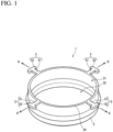
- FIG. 1 is a schematic perspective view of a gasket of the present embodiment.
- FIG. 2 is a schematic perspective view depicting a state where the gasket of the present embodiment is attached to an attachment-receiving object.
- FIG. 3 is a schematic side view of a state where the gasket of the present embodiment is attached to the attachment-receiving object.
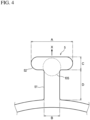
- FIG. 4 is schematic plan view representing the main surface of a protrusion.
- a gasket 1 of the present embodiment has a housing section 3.
- the housing section 3 houses, as a to-be-protected object, an electrical part such as a connector of a wire used for an automobile.
- the housing section 3 protects the to-be-protected object from oil, dust, or the like.
- the housing section 3 and protrusions 5 mentioned later include rubber.
- the type of rubber is not limited particularly, and, for example, may be a rubber similar to that used for conventionally known gaskets.
- the size, thickness, shape, and the like of the rubber also may be similar to those of the conventionally known gaskets.
- the housing section 3 is cylindrical. Note that as long as the housing section 3 has an opening 31, the shape and the like of the housing section 3 are not limited particularly.
- the cylindrical housing section 3 depicted in FIG. 1 to FIG. 3 has the opening 31 and an opening 32 positioned on a side opposite to the opening 31. Note that the housing section 3 does not have to have the opening 32. That is, the opening 32 may be closed by a plate-like member or the like.
- the housing section 3 has the opening 31.
- the opening 31 is defined by an end portion 30 of the housing section 3.
- the to-be-protected object such as an electrical part is put inside the housing section 3 from the opening 31. Thereby, the to-be-protected object can be protected inside the housing section 3.
- the housing section 3 is arranged such that the opening 31 is closely attached to the surface of an attachment-receiving object 100.
- FIG. 1 to FIG. 3 depict a form in which the protrusions 5 are directly continuous with the end portion 30. Note that another section such as a flange may be formed on the end portion 30, and, by being continuous with the section, the protrusions 5 may become continuous with the end portion 30 indirectly.
- the number of the protrusions 5 is not limited particularly.
- the gasket 1 preferably has two or more protrusions 5, more preferably has three or more protrusions 5, and further preferably has four or more protrusions 5. Thereby, superior anti-disengagement property can be attained.
- the gasket 1 has eight or fewer protrusions 5.
- the four protrusions 5 are arranged evenly at the intervals of 90 degrees in the circumferential direction of the circular opening 31.
- the protrusions 5 are preferably arranged evenly in the circumferential direction of the opening 31.
- the protrusions 5 are preferably arranged evenly in the circumferential direction.
- Each protrusion 5 has a trunk portion 51 and a branch portion 52.
- Each protrusion 5 depicted in FIG. 1 to FIG. 3 has only the trunk portion 51 and the branch portion 52.
- the trunk portion 51 extends in a direction X (radially-outer-side direction) away from the end portion 30 in the radial direction.
- the trunk portion 51 preferably extends outward linearly from the center of the circle radially.
- the trunk portion 51 preferably extends outward linearly from the center of the opening 31 radially.
- the branch portion 52 extends from the trunk portion 51 in a direction different from the direction X.
- the branch portion 52 depicted in FIG. 1 to FIG. 3 extends from the front end of the trunk portion 51 in a direction which is perpendicular to the direction X, and is generally parallel to the surface of the attachment-receiving object.
- the branch portion 52 is arranged at the front end of the trunk portion 51, and the protrusion 5 is T-shaped as a whole.
- branch portion 52 extends in a direction different from the direction X in which the trunk portion 51 extends.
- the branch portion 52 does not necessarily have to extend in a direction perpendicular to the direction X.
- the protrusion 5 does not necessarily have to be T-shaped.
- the branch portion 52 may not be positioned at the front end of the trunk portion 51, but a part of the trunk portion 51 or the like may extend ahead from the branch portion 52 in the direction X, and the protrusion 5 may have a cruciform shape as a whole.
- Both the trunk portion 51 and the branch portion 52 have strip-like shapes.
- the trunk portion 51 and the branch portion 52 are continuous with each other. That is, both the trunk portion 51 and the branch portion 52 have certain lengths of widths, and the protrusion 5 as a whole has a form like one taken out from a thin sheet.
- the main surface of the protrusion 5 (the main surfaces of the trunk portion 51 and the branch portion 52) faces the surface of the attachment-receiving object 100.
- the surface of the attachment-receiving object 100 and the main surface of the protrusion 5 are preferably generally parallel to each other.
- the shape of the protrusion 5 is explained in detail by using FIG. 4 .
- FIG. 4 is schematic plan view representing the main surface of the protrusion 5.
- the protrusion 5 is T-shaped as a whole.
- both a width B of the trunk portion 51 and a width C of the branch portion 52 are preferably smaller than the diameter of an attachment hole 105 represented by a dotted line. Note that the width B and/or the width C may be the same as or slightly greater than the diameter of the attachment hole 105.
- An entire length A of the branch portion 52 in a direction which is perpendicular to the direction X, and is generally parallel to the surface of the attachment-receiving object 100 is preferably greater than the diameter of the attachment hole 105.
- a length D of the trunk portion 51 is not limited particularly.
- the trunk portion 51 preferably has such a length D that, in a state where the gasket 1 is arranged on the surface of the attachment-receiving object 100, and the protrusion 5 has not been inserted into the attachment hole 105, it is possible to attain a state where the trunk portion 51 and the branch portion 52 cover the entire attachment hole 105, and the attachment hole 105 cannot be seen, as depicted in FIG. 4 .
- the attachment hole 105 is circular in FIG. 1 to FIG. 4 , the attachment hole 105 does not have to be circular. In a case where the attachment hole 105 is not circular, the diameter of the attachment hole 105 is equal to the diameter of a circle with an equal area.
- FIG. 5A and FIG. 5B A method of attaching the gasket 1 of the present embodiment to the surface of the attachment-receiving object 100 is explained by using FIG. 5A and FIG. 5B .
- the gasket 1 is arranged on the surface of the attachment-receiving object 100. Thereafter, as depicted in FIG. 5B , a rod-like jig 200 is used to press and insert the protrusions 5 into the attachment holes 105. Then, as depicted in FIG. 2 to FIG. 3 , the branch portions 52 are caught when the protrusions 5 are caused to penetrate the attachment holes 105. In this manner, the gasket 1 is attached to the surface of the attachment-receiving object 100.
- the method of attaching the gasket 1 to the surface of the attachment-receiving object 100 is not limited to the method explained using FIG. 5A and FIG. 5B .
- the gasket 1 of the present embodiment contributes to space saving.
- the gasket 1 of the present embodiment has a shape which can be formed easily by molding.
Landscapes
- Engineering & Computer Science (AREA)
- General Engineering & Computer Science (AREA)
- Mechanical Engineering (AREA)
- Gasket Seals (AREA)
Abstract
Description
- The present disclosure relates to a gasket.
- A rubber-made seal part used for the purpose of preventing the entrance of foreign matters from the outside is required to be not disengaged from a predetermined position for realizing its primary function. For example, a section of concern about disengagement of a seal at an assembly step of an equipment unit is given an engagement structure that prevents disengagement of the seal (e.g.
JP-2020-193655-A - Patent Literature 1 discloses a rubber-made gasket having a cylindrical portion in which an electrical part is arranged, a flange formed at an end portion of the cylindrical portion, and a hook protruding from the flange. The hook has a base portion coupled to the flange, a front end portion coupled to the base portion, and an axis extending through the base portion and the front end portion. The front end portion has a portion whose dimension orthogonal to the axis is greater than a dimension thereof orthogonal to the axis of the base portion, and a taper portion whose dimension orthogonal to the axis decreases as the distance from the base portion increases. A cavity portion extending along the axis is formed at the front end portion. The gasket can be easily attached to a predetermined location.
- A protrusion having an umbrella-like hook of the gasket described in Patent Literature 1 provides superior anti-disengagement property. Accordingly, it is applied to a seal part for a section that is of concern about disengagement or a section that is desired to surely prevent disengagement.
- When a structure in which an attachment hole is provided to an attachment, and an umbrella portion is caused to be engaged with the attachment hole by pressing the umbrella portion therein is used, the engagement force is improved by making the umbrella outer radius greater than the diameter of the attachment hole. On the other hand, it becomes difficult to attach the umbrella portion, and the difficulty of attachment work increases depending on the structure or the like of an attachment-receiving object. Improvement of the attachability is demanded for space saving of units.
- In addition, the molding difficulty of a seal part having an umbrella portion like the one described in Patent Literature 1 is high. Typically, such a part is molded by using a mold. When umbrella-like protrusions embedded in a mold are pulled out of and released from a mold, there is a possibility that the protrusions are damaged.
- An object of the present disclosure is to provide a gasket that can be easily attached to the surface of an attachment-receiving object, contributes to space saving, and has a shape that can be easily formed by molding.
- One aspect of the present disclosure is a rubber-made gasket that can be attached to a surface of an attachment-receiving object having an attachment hole, the rubber-made gasket including:
- a housing section having an opening to be closely attached to the attachment-receiving object; and
- a protrusion that is directly or indirectly continuous with an end portion of the housing section, and has a main surface to face a surface of the attachment-receiving object, the protrusion having: a strip-like trunk portion extending from the end portion in a radially-outer-side direction of the housing section; and a strip-like branch portion extending from the trunk portion in a direction different from a radial direction of the housing section, the protrusion being able to be inserted into the attachment hole.
- The present disclosure can provide a gasket that can be easily attached to the surface of an attachment-receiving object, contributes to space saving, and has a shape that can be easily formed by molding.
-
-
FIG. 1 is a schematic perspective view of a gasket of the present embodiment. -
FIG. 2 is a schematic perspective view depicting a state where the gasket of the present embodiment is attached to an attachment-receiving object. -
FIG. 3 is a schematic side view of a state where the gasket of the present embodiment is attached to the attachment-receiving object. -
FIG. 4 is schematic plan view representing the main surface of a protrusion. -
FIG. 5A and FIG. 5B are schematic diagrams for explaining a method of attaching the gasket of the present embodiment to the attachment-receiving object. - Hereinbelow, a gasket of the present embodiment is explained by using the figures.
FIG. 1 is a schematic perspective view of a gasket of the present embodiment.FIG. 2 is a schematic perspective view depicting a state where the gasket of the present embodiment is attached to an attachment-receiving object.FIG. 3 is a schematic side view of a state where the gasket of the present embodiment is attached to the attachment-receiving object.FIG. 4 is schematic plan view representing the main surface of a protrusion. - As depicted in
FIG. 1 to FIG. 3 , a gasket 1 of the present embodiment has ahousing section 3. - For example, the
housing section 3 houses, as a to-be-protected object, an electrical part such as a connector of a wire used for an automobile. Thehousing section 3 protects the to-be-protected object from oil, dust, or the like. - The
housing section 3 andprotrusions 5 mentioned later include rubber. The type of rubber is not limited particularly, and, for example, may be a rubber similar to that used for conventionally known gaskets. For example, the size, thickness, shape, and the like of the rubber also may be similar to those of the conventionally known gaskets. - In
FIG. 1 to FIG. 3 , thehousing section 3 is cylindrical. Note that as long as thehousing section 3 has anopening 31, the shape and the like of thehousing section 3 are not limited particularly. - The
cylindrical housing section 3 depicted inFIG. 1 to FIG. 3 has theopening 31 and anopening 32 positioned on a side opposite to the opening 31. Note that thehousing section 3 does not have to have theopening 32. That is, the opening 32 may be closed by a plate-like member or the like. - The
housing section 3 has theopening 31. The opening 31 is defined by anend portion 30 of thehousing section 3. - The to-be-protected object such as an electrical part is put inside the
housing section 3 from theopening 31. Thereby, the to-be-protected object can be protected inside thehousing section 3. - As depicted in
FIG. 2 to FIG. 3 , after the to-be-protected object is put inside thehousing section 3 from theopening 31, thehousing section 3 is arranged such that theopening 31 is closely attached to the surface of an attachment-receivingobject 100. - The
protrusions 5 are directly or indirectly continuous with theend portion 30 of thehousing section 3.FIG. 1 to FIG. 3 depict a form in which theprotrusions 5 are directly continuous with theend portion 30. Note that another section such as a flange may be formed on theend portion 30, and, by being continuous with the section, theprotrusions 5 may become continuous with theend portion 30 indirectly. - Whereas the gasket 1 depicted in
FIG. 1 to FIG. 3 has fourprotrusions 5, the number of theprotrusions 5 is not limited particularly. Note that the gasket 1 preferably has two ormore protrusions 5, more preferably has three ormore protrusions 5, and further preferably has four ormore protrusions 5. Thereby, superior anti-disengagement property can be attained. For example, the gasket 1 has eight orfewer protrusions 5. - In the gasket 1 depicted in
FIG. 1 to FIG. 3 , the fourprotrusions 5 are arranged evenly at the intervals of 90 degrees in the circumferential direction of thecircular opening 31. In a case where the gasket 1 has two ormore protrusions 5 also, theprotrusions 5 are preferably arranged evenly in the circumferential direction of theopening 31. - In a case where the
opening 31 is not circular, but, for example, oval or rectangular also, theprotrusions 5 are preferably arranged evenly in the circumferential direction. - Each
protrusion 5 has atrunk portion 51 and abranch portion 52. Eachprotrusion 5 depicted inFIG. 1 to FIG. 3 has only thetrunk portion 51 and thebranch portion 52. - The
trunk portion 51 extends in a direction X (radially-outer-side direction) away from theend portion 30 in the radial direction. - In a case where the
opening 31 is circular as depicted inFIG. 1 to FIG. 3 , thetrunk portion 51 preferably extends outward linearly from the center of the circle radially. - In a case where the
opening 31 is not circular also, thetrunk portion 51 preferably extends outward linearly from the center of theopening 31 radially. - The
branch portion 52 extends from thetrunk portion 51 in a direction different from the direction X. - The
branch portion 52 depicted inFIG. 1 to FIG. 3 extends from the front end of thetrunk portion 51 in a direction which is perpendicular to the direction X, and is generally parallel to the surface of the attachment-receiving object. Thebranch portion 52 is arranged at the front end of thetrunk portion 51, and theprotrusion 5 is T-shaped as a whole. - Note that it is sufficient if the
branch portion 52 extends in a direction different from the direction X in which thetrunk portion 51 extends. Thebranch portion 52 does not necessarily have to extend in a direction perpendicular to the direction X. - The
protrusion 5 does not necessarily have to be T-shaped. For example, thebranch portion 52 may not be positioned at the front end of thetrunk portion 51, but a part of thetrunk portion 51 or the like may extend ahead from thebranch portion 52 in the direction X, and theprotrusion 5 may have a cruciform shape as a whole. - Both the
trunk portion 51 and thebranch portion 52 have strip-like shapes. Thetrunk portion 51 and thebranch portion 52 are continuous with each other. That is, both thetrunk portion 51 and thebranch portion 52 have certain lengths of widths, and theprotrusion 5 as a whole has a form like one taken out from a thin sheet. - The main surface of the protrusion 5 (the main surfaces of the
trunk portion 51 and the branch portion 52) faces the surface of the attachment-receivingobject 100. Here, the surface of the attachment-receivingobject 100 and the main surface of theprotrusion 5 are preferably generally parallel to each other. - The shape of the
protrusion 5 is explained in detail by usingFIG. 4 . -
FIG. 4 is schematic plan view representing the main surface of theprotrusion 5. InFIG. 4 , theprotrusion 5 is T-shaped as a whole. - As depicted in
FIG. 4 , both a width B of thetrunk portion 51 and a width C of thebranch portion 52 are preferably smaller than the diameter of anattachment hole 105 represented by a dotted line. Note that the width B and/or the width C may be the same as or slightly greater than the diameter of theattachment hole 105. - An entire length A of the
branch portion 52 in a direction which is perpendicular to the direction X, and is generally parallel to the surface of the attachment-receivingobject 100 is preferably greater than the diameter of theattachment hole 105. - A length D of the
trunk portion 51 is not limited particularly. Thetrunk portion 51 preferably has such a length D that, in a state where the gasket 1 is arranged on the surface of the attachment-receivingobject 100, and theprotrusion 5 has not been inserted into theattachment hole 105, it is possible to attain a state where thetrunk portion 51 and thebranch portion 52 cover theentire attachment hole 105, and theattachment hole 105 cannot be seen, as depicted inFIG. 4 . - Note that whereas the
attachment hole 105 is circular inFIG. 1 to FIG. 4 , theattachment hole 105 does not have to be circular. In a case where theattachment hole 105 is not circular, the diameter of theattachment hole 105 is equal to the diameter of a circle with an equal area. - A method of attaching the gasket 1 of the present embodiment to the surface of the attachment-receiving
object 100 is explained by usingFIG. 5A and FIG. 5B . - As depicted in
FIG. 5A , the gasket 1 is arranged on the surface of the attachment-receivingobject 100. Thereafter, as depicted inFIG. 5B , a rod-like jig 200 is used to press and insert theprotrusions 5 into the attachment holes 105. Then, as depicted inFIG. 2 to FIG. 3 , thebranch portions 52 are caught when theprotrusions 5 are caused to penetrate the attachment holes 105. In this manner, the gasket 1 is attached to the surface of the attachment-receivingobject 100. - Note that the method of attaching the gasket 1 to the surface of the attachment-receiving
object 100 is not limited to the method explained usingFIG. 5A and FIG. 5B . - In this manner, large force is not necessary for inserting the
protrusions 5 into the attachment holes 105, and the gasket 1 of the present embodiment can be easily attached to the surface of the attachment-receivingobject 100. - The gasket 1 of the present embodiment contributes to space saving.
- In addition, the gasket 1 of the present embodiment has a shape which can be formed easily by molding.
-
- 1: gasket
- 3: housing section
- 30: end portion
- 31, 32: opening
- 5: protrusion
- 51: trunk portion
- 52: branch portion
- 100: attachment-receiving object
- 105: attachment hole
- 200: jig
Claims (9)
- A rubber-made gasket that can be attached to a surface of an attachment-receiving object having an attachment hole, the rubber-made gasket comprising:a housing section having an opening to be closely attached to the attachment-receiving object; anda protrusion that is directly or indirectly continuous with an end portion of the housing section, and has a main surface to face a surface of the attachment-receiving object, the protrusion having: a strip-like trunk portion extending from the end portion in a radially-outer-side direction of the housing section; and a strip-like branch portion extending from the trunk portion in a direction different from a radial direction of the housing section, the protrusion being able to be inserted into the attachment hole.
- The gasket according to claim 1, wherein the housing section is cylindrical.
- The gasket according to claim 1 or 2, comprising a plurality of the protrusions that are arranged evenly in a circumferential direction of the opening.
- The gasket according to any one of claims 1 to 3, wherein the branch portion extends from the trunk portion in a direction perpendicular to the radially-outer-side direction of the housing section.
- The gasket according to any one of claims 1 to 4, wherein the branch portion is arranged at a front end of the trunk portion.
- The gasket according to any one of claims 1 to 5, wherein the trunk portion and the branch portion are continuous.
- The gasket according to any one of claims 1 to 6, wherein both a width of the trunk portion and a width of the branch portion are smaller than a diameter of the attachment hole.
- The gasket according to any one of claims 1 to 7, wherein an entire length of the branch portion in a direction perpendicular to the radial direction of the housing section is greater than a diameter of the attachment hole.
- The gasket according to any one of claims 1 to 8, wherein the branch portion is caught by the attachment-receiving object when the protrusion is inserted into the attachment hole.
Applications Claiming Priority (2)
| Application Number | Priority Date | Filing Date | Title |
|---|---|---|---|
| JP2021127305 | 2021-08-03 | ||
| PCT/JP2022/027716 WO2023013382A1 (en) | 2021-08-03 | 2022-07-14 | Gasket |
Publications (1)
| Publication Number | Publication Date |
|---|---|
| EP4382753A1 true EP4382753A1 (en) | 2024-06-12 |
Family
ID=85155976
Family Applications (1)
| Application Number | Title | Priority Date | Filing Date |
|---|---|---|---|
| EP22852806.3A Withdrawn EP4382753A1 (en) | 2021-08-03 | 2022-07-14 | Gasket |
Country Status (5)
| Country | Link |
|---|---|
| US (1) | US20240337319A1 (en) |
| EP (1) | EP4382753A1 (en) |
| JP (1) | JPWO2023013382A1 (en) |
| CN (1) | CN117716152A (en) |
| WO (1) | WO2023013382A1 (en) |
Families Citing this family (1)
| Publication number | Priority date | Publication date | Assignee | Title |
|---|---|---|---|---|
| WO2025121084A1 (en) * | 2023-12-04 | 2025-06-12 | 株式会社パイオラックス | Seal ring and seal ring holding structure |
Family Cites Families (15)
| Publication number | Priority date | Publication date | Assignee | Title |
|---|---|---|---|---|
| US3643968A (en) * | 1969-12-24 | 1972-02-22 | Hercules Packing Corp | Gasket |
| JPH02286859A (en) * | 1989-04-28 | 1990-11-27 | Nippon Reinz Co Ltd | Cylinder head gasket |
| US4905758A (en) * | 1989-07-03 | 1990-03-06 | Tranter, Inc. | Plate heat exchanger |
| JPH09112699A (en) * | 1995-10-17 | 1997-05-02 | Sumitomo Wiring Syst Ltd | Seal member mounting structure |
| KR100196779B1 (en) * | 1997-01-06 | 1999-06-15 | 이동환 | Gasket attachment shape for plate type heat exchanger |
| JPH11126647A (en) * | 1997-10-21 | 1999-05-11 | Yazaki Corp | Annular packing and mounting structure of annular packing |
| DE10060236C1 (en) * | 2000-12-05 | 2002-07-04 | Itw Automotive Prod Gmbh & Co | Clipart-like component made of plastic |
| JP2004006112A (en) * | 2002-05-31 | 2004-01-08 | Sumitomo Wiring Syst Ltd | Water proof connector |
| JP2004327169A (en) * | 2003-04-23 | 2004-11-18 | Yazaki Corp | Packing and connector with packing |
| JP4246726B2 (en) * | 2005-10-21 | 2009-04-02 | 石川ガスケット株式会社 | Metal laminated gasket |
| JP4559369B2 (en) * | 2006-02-03 | 2010-10-06 | 矢崎総業株式会社 | Packing mounting structure |
| JP5390998B2 (en) * | 2009-09-01 | 2014-01-15 | 矢崎総業株式会社 | connector |
| JP5801080B2 (en) * | 2011-03-30 | 2015-10-28 | ニチアス株式会社 | Cylinder head gasket |
| JP2018060730A (en) * | 2016-10-07 | 2018-04-12 | 住友電装株式会社 | connector |
| JP2020193655A (en) | 2019-05-28 | 2020-12-03 | Nok株式会社 | gasket |
-
2022
- 2022-07-14 US US18/293,930 patent/US20240337319A1/en not_active Abandoned
- 2022-07-14 CN CN202280053059.XA patent/CN117716152A/en active Pending
- 2022-07-14 WO PCT/JP2022/027716 patent/WO2023013382A1/en not_active Ceased
- 2022-07-14 EP EP22852806.3A patent/EP4382753A1/en not_active Withdrawn
- 2022-07-14 JP JP2023539741A patent/JPWO2023013382A1/ja active Pending
Also Published As
| Publication number | Publication date |
|---|---|
| CN117716152A (en) | 2024-03-15 |
| WO2023013382A1 (en) | 2023-02-09 |
| JPWO2023013382A1 (en) | 2023-02-09 |
| US20240337319A1 (en) | 2024-10-10 |
Similar Documents
| Publication | Publication Date | Title |
|---|---|---|
| CN103091792B (en) | Connector | |
| JP5243914B2 (en) | Hole plug | |
| JP4571154B2 (en) | Airtight electrical connector parts | |
| US9689108B2 (en) | Dryer duct connector | |
| US20240337319A1 (en) | Gasket | |
| US7905695B2 (en) | Methods and apparatus for locking element | |
| US20140284335A1 (en) | Receptacle for fasteners and an associated installation method | |
| KR20170127545A (en) | The sealing portion | |
| US3701303A (en) | Stop ring | |
| US4088327A (en) | Sealing ring with tabs for holding for assembly | |
| KR20150099815A (en) | Connector member including a locking element | |
| US11493130B2 (en) | Hole plug | |
| US20090159332A1 (en) | Cable seal assembly | |
| CN205657399U (en) | Wear wall plug | |
| US7423216B2 (en) | Dual action sealing gasket and use thereof in an electrical housing assembly | |
| GB2425365A (en) | Seal for cable gland assembly and tool therefor | |
| US20220341457A1 (en) | Fasteners | |
| WO2019037709A1 (en) | Cable gland | |
| CN223152461U (en) | Fastening assembly and mounting structure | |
| CN218300429U (en) | Plug fastening anti-loosening device | |
| CN220492567U (en) | Wire clamping structure | |
| CN219843854U (en) | Shell assembly of energy storage power supply | |
| SE1951186A1 (en) | A grommet assembly and a vehicle comprising a power train component with a grommet assembly | |
| CN210416948U (en) | Air conditioner box and marine air conditioner | |
| US20170005439A1 (en) | Electrical connector with electromagnetic shielding and removable foolproofing system |
Legal Events
| Date | Code | Title | Description |
|---|---|---|---|
| STAA | Information on the status of an ep patent application or granted ep patent |
Free format text: STATUS: THE INTERNATIONAL PUBLICATION HAS BEEN MADE |
|
| PUAI | Public reference made under article 153(3) epc to a published international application that has entered the european phase |
Free format text: ORIGINAL CODE: 0009012 |
|
| STAA | Information on the status of an ep patent application or granted ep patent |
Free format text: STATUS: REQUEST FOR EXAMINATION WAS MADE |
|
| 17P | Request for examination filed |
Effective date: 20240126 |
|
| AK | Designated contracting states |
Kind code of ref document: A1 Designated state(s): AL AT BE BG CH CY CZ DE DK EE ES FI FR GB GR HR HU IE IS IT LI LT LU LV MC MK MT NL NO PL PT RO RS SE SI SK SM TR |
|
| STAA | Information on the status of an ep patent application or granted ep patent |
Free format text: STATUS: THE APPLICATION HAS BEEN WITHDRAWN |
|
| 18W | Application withdrawn |
Effective date: 20240807 |