EP4382655A1 - Back wall enclosure for a drum within a laundry appliance that sesparates a processing space from a blower housing - Google Patents
Back wall enclosure for a drum within a laundry appliance that sesparates a processing space from a blower housing Download PDFInfo
- Publication number
- EP4382655A1 EP4382655A1 EP23214011.1A EP23214011A EP4382655A1 EP 4382655 A1 EP4382655 A1 EP 4382655A1 EP 23214011 A EP23214011 A EP 23214011A EP 4382655 A1 EP4382655 A1 EP 4382655A1
- Authority
- EP
- European Patent Office
- Prior art keywords
- drum
- tub
- airflow path
- back wall
- blower
- Prior art date
- Legal status (The legal status is an assumption and is not a legal conclusion. Google has not performed a legal analysis and makes no representation as to the accuracy of the status listed.)
- Granted
Links
Images




Classifications
-
- D—TEXTILES; PAPER
- D06—TREATMENT OF TEXTILES OR THE LIKE; LAUNDERING; FLEXIBLE MATERIALS NOT OTHERWISE PROVIDED FOR
- D06F—LAUNDERING, DRYING, IRONING, PRESSING OR FOLDING TEXTILE ARTICLES
- D06F37/00—Details specific to washing machines covered by groups D06F21/00 - D06F25/00
- D06F37/26—Casings; Tubs
- D06F37/267—Tubs specially adapted for mounting thereto components or devices not provided for in preceding subgroups
-
- D—TEXTILES; PAPER
- D06—TREATMENT OF TEXTILES OR THE LIKE; LAUNDERING; FLEXIBLE MATERIALS NOT OTHERWISE PROVIDED FOR
- D06F—LAUNDERING, DRYING, IRONING, PRESSING OR FOLDING TEXTILE ARTICLES
- D06F25/00—Washing machines with receptacles, e.g. perforated, having a rotary movement, e.g. oscillatory movement, the receptacle serving both for washing and for centrifugally separating water from the laundry and having further drying means, e.g. using hot air
-
- D—TEXTILES; PAPER
- D06—TREATMENT OF TEXTILES OR THE LIKE; LAUNDERING; FLEXIBLE MATERIALS NOT OTHERWISE PROVIDED FOR
- D06F—LAUNDERING, DRYING, IRONING, PRESSING OR FOLDING TEXTILE ARTICLES
- D06F58/00—Domestic laundry dryers
- D06F58/02—Domestic laundry dryers having dryer drums rotating about a horizontal axis
-
- D—TEXTILES; PAPER
- D06—TREATMENT OF TEXTILES OR THE LIKE; LAUNDERING; FLEXIBLE MATERIALS NOT OTHERWISE PROVIDED FOR
- D06F—LAUNDERING, DRYING, IRONING, PRESSING OR FOLDING TEXTILE ARTICLES
- D06F58/00—Domestic laundry dryers
- D06F58/20—General details of domestic laundry dryers
- D06F58/24—Condensing arrangements
-
- D—TEXTILES; PAPER
- D06—TREATMENT OF TEXTILES OR THE LIKE; LAUNDERING; FLEXIBLE MATERIALS NOT OTHERWISE PROVIDED FOR
- D06F—LAUNDERING, DRYING, IRONING, PRESSING OR FOLDING TEXTILE ARTICLES
- D06F37/00—Details specific to washing machines covered by groups D06F21/00 - D06F25/00
- D06F37/02—Rotary receptacles, e.g. drums
- D06F37/04—Rotary receptacles, e.g. drums adapted for rotation or oscillation about a horizontal or inclined axis
-
- D—TEXTILES; PAPER
- D06—TREATMENT OF TEXTILES OR THE LIKE; LAUNDERING; FLEXIBLE MATERIALS NOT OTHERWISE PROVIDED FOR
- D06F—LAUNDERING, DRYING, IRONING, PRESSING OR FOLDING TEXTILE ARTICLES
- D06F37/00—Details specific to washing machines covered by groups D06F21/00 - D06F25/00
- D06F37/30—Driving arrangements
Definitions
- the present disclosure generally relates to a laundry appliance, and more specifically, to a combination washing and drying appliance that incorporates a back wall for the rotating drum that separates the processing space within the drum from a blower housing that is contained within a space defined between the tub and the rotating drum.
- a combination washing and drying appliance includes a tub that is disposed within a cabinet.
- a drum is rotationally operable within the tub about a rotational axis.
- An airflow path is defined within an interstitial space between the drum and the tub.
- a blower fan operates to direct process air through the airflow path.
- the blower fan is disposed within a blower enclosure that is defined by a back wall of the drum and a blower housing that is attached to the tub. Engagement of the back wall of the drum and the blower housing of the tub defines a slidable engagement that is selectively sealed during operation of the blower fan to prevent the process air from leaving the airflow path and to further prevent aspiration of ambient air to the airflow path.
- a combination washing and drying appliance includes a tub that is disposed within a cabinet.
- a drum has a back wall and is rotationally operable within the tub about a rotational axis.
- An airflow path is defined within an interstitial space between the drum and the tub.
- a drain is disposed within a lower section of the tub.
- An outlet for the drain is disposed within the airflow path.
- a blower fan delivers process air through the airflow path that is contained within the tub.
- the blower fan is disposed between the back wall of the drum and a blower housing of the tub.
- the back wall rotates with the drum and is slidably engaged with the blower housing to define a labyrinth seal.
- the blower fan rotationally operates within a blower enclosure that is defined between the back wall and the blower housing. Moisture collected in the airflow path is directed to the outlet of the drain.
- an air handling system for a laundry appliance includes a tub that is disposed within a cabinet.
- a drum has a back wall and is rotationally operable within the tub about a rotational axis.
- An airflow path is defined within an interstitial space between the drum and the tub.
- a blower fan delivers process air through the airflow path that is contained within the tub.
- the blower fan is disposed between the back wall of the drum and a blower housing of the tub.
- the back wall rotates with the drum and is slidably engaged with the blower housing to define a labyrinth seal.
- the blower fan rotationally operates within a blower enclosure that is defined between the back wall and the blower housing.
- the present illustrated embodiments reside primarily in combinations of method steps and apparatus components related to a tub assembly for a combination washing and drying appliance that incorporates a rotating drum having a back wall that separates the processing space from a blower housing that is contained in the space between the tub and the rotating drum. Accordingly, the apparatus components and method steps have been represented, where appropriate, by conventional symbols in the drawings, showing only those specific details that are pertinent to understanding the embodiments of the present disclosure so as not to obscure the disclosure with details that will be readily apparent to those of ordinary skill in the art having the benefit of the description herein. Further, like numerals in the description and drawings represent like elements.
- the terms “upper,” “lower,” “right,” “left,” “rear,” “front,” “vertical,” “horizontal,” and derivatives thereof shall relate to the disclosure as oriented in FIG. 1 .
- the term “front” shall refer to the surface of the element closer to an intended viewer, and the term “rear” shall refer to the surface of the element further from the intended viewer.
- the disclosure may assume various alternative orientations, except where expressly specified to the contrary.
- the specific devices and processes illustrated in the attached drawings, and described in the following specification are simply exemplary embodiments of the inventive concepts defined in the appended claims. Hence, specific dimensions and other physical characteristics relating to the embodiments disclosed herein are not to be considered as limiting, unless the claims expressly state otherwise.
- reference numeral 10 generally designates a tub assembly having a tub 12, a drum 14, and a blower assembly 16 that is disposed between the drum 14 and the tub 12.
- the tub assembly 10 is typically incorporated as part of a combination washing and drying appliance 18.
- This appliance 18 includes an airflow path 20 that is disposed within the tub assembly 10.
- the airflow path 20 is entirely disposed within the tub 12 for moving process air 22 within an interstitial space 24 defined between the tub 12 and the drum 14.
- the airflow path 20 also extends through a processing space 26 defined within the drum 14.
- the appliance 18 includes the tub 12 that is disposed within an outer cabinet 28.
- the drum 14 is rotationally operable within the tub 12 and operates about a rotational axis 30.
- the airflow path 20 is defined within the interstitial space 24 that is located between the drum 14 and the tub 12. At least a portion of this interstitial space 24 defines a blower enclosure 32 that houses the blower assembly 16.
- a blower fan 34 of the blower assembly 16 operates to direct the process air 22 through the airflow path 20.
- the blower fan 34 is disposed within the blower enclosure 32 that is defined by a back wall 36, which is attached to the drum 14, and a blower housing 38, which is attached to the tub 12.
- Engagement of the back wall 36 of the drum 14 with the blower housing 38 of the tub 12 defines a slidable engagement 40 that allows the drum 14, along with the back wall 36, to rotate relative to the tub 12 and the blower housing 38.
- Engagement of the back wall 36 of the drum 14 with the blower housing 38 defines the slidable engagement 40 that is selectively sealed during operation of the blower fan 34 about the rotational axis 30 to prevent aspiration of ambient air 42 into the airflow path 20. Additionally, this selectively sealed engagement can also prevent the process air 22 from leaving the airflow path 20 into areas that are outside of the airflow path 20 defined between the tub 12 and the drum 14.
- the blower fan 34 typically operates about the same rotational axis 30 as that of the drum 14. Additionally, the back wall 36 is fixedly attached to the drum 14 and the blower housing 38 is fixedly attached to the tub 12.
- the slidable engagement 40 that is formed between the drum 14 and the tub 12 can be in the form of a labyrinth seal 50 that is formed at an interface between the back wall 36 of the drum 14 and the blower housing 38.
- This labyrinth seal 50 provides for the slidable engagement 40 between the back wall 36 of the drum 14 and the blower housing 38 of the tub 12.
- the slidable engagement 40 of the labyrinth seal 50 allows the drum 14 to operate within the tub 12.
- This labyrinth seal 50 can include various labyrinth-type engagements that can include an annular protrusion 52 of the back wall 36 of the drum 14 that extends toward the blower housing 38.
- the blower housing 38 can include an annular channel 54 that receives the annular protrusion 52. Through this engagement between the annular protrusion 52 and the annular channel 54, the labyrinth seal 50 allows for the rotational operation of the drum 14 relative to the tub 12.
- the blower fan 34 defines a high-pressure area 60 within the blower enclosure 32.
- This high-pressure area 60 is typically disposed near the slidable engagement 40 between the back wall 36 and the blower housing 38. Accordingly, this labyrinth seal 50 is acted upon by the increased air pressure 62 within the high-pressure area 60.
- This increased air pressure 62 serves to increase the seal strength of the labyrinth seal 50 such that ambient air 42 is less capable or incapable of infiltrating into the airflow path 20 via the labyrinth seal 50.
- the increased air pressure 62 within the high-pressure area 60 prevents aspiration of ambient air 42 into the airflow path 20 via the interface defined by the labyrinth seal 50. Also, the slidable and sealed engagement of the labyrinth seal 50 during operation of the blower fan 34 prevents expiration of the process air 22 from the airflow path 20, through the labyrinth seal 50 and to areas external of the airflow path 20.
- a portion of the airflow path 20 extends through the interstitial space 24 defined between the tub 12 and the drum 14.
- the process air 22 is drawn from the processing space 26 of the drum 14 and into the blower enclosure 32 through an aperture 70 defined within the back wall 36 of the drum 14.
- One or more filtration members 72 can be positioned proximate the aperture 70 of the back wall 36 to provide a filtering functionality as the process air 22 moves through the aperture 70 defined within the back wall 36.
- These filtration members 72 can include perforated panels, mesh screens, and other similar filtration mechanism that can be used to separate particulate matter from the process air 22 (or other fluid) moving through the airflow path 20.
- the filtration member 72 filters the particulate matter as the process air 22 moves from the processing space 26 and into the blower enclosure 32.
- the filtration member 72 can be incorporated into a contoured wall 66 that is positioned forward of the back wall 36.
- This contoured wall 66 can include ridges 80 and valleys 82 as well as a series of perforated sections 74 that define the filtration member 72.
- the contoured wall 66 can be attached to the back wall 36 and can rotate with the drum 14 and the back wall 36.
- the contoured wall 66 in certain aspects of the device, can also be selectively operable to rotate independently with respect to the back wall 36 or in unison with the back wall 36.
- the back wall 36 of the drum 14 defines a portion of the processing space 26.
- the filtration member 72 can be attached to the back wall 36.
- the filtration member 72 is attached to the back wall 36 as the contoured wall 66 described herein.
- this contoured wall 66 can include the various ridges 80 and valleys 82. These ridges 80 and valleys 82 are typically positioned adjacent to the back wall 36 for providing an agitating or tumbling effect on articles being processed in the drum 14.
- the contoured wall 66 can include the filtration member 72 in the form of a plurality of perforated sections 74 that allow process air 22 to move therethrough, while capturing particulate material within the filtration member 72.
- the contoured wall 66 and the perforated sections 74 of the filtration member 72 allow the process air 22 to move through the aperture 70 defined within the back wall 36 and into the blower enclosure 32.
- the contoured wall can define the processing space 26.
- the back wall 36 defines the blower enclosure 32 that houses the blower fan 34. It is also contemplated that the back wall 36, in certain aspects of the device, can include the ridges 80 and valleys 82 that define the processing space 26.
- the airflow path 20 continues through the blower enclosure 32 that is defined between the back wall 36 of the drum 14 and the blower housing 38 of the tub 12.
- this blower housing 38 can take the form of a cochlear housing that can be used to direct the process air 22 from the blower fan 34 to downstream portions of the airflow path 20.
- These downstream portions of the airflow path 20 are typically positioned within a lower section 90 of the tub 12 and beneath the drum 14. The process air 22 then moves upward to be reintroduced into the processing space 26 of the rotating drum 14.
- certain heat exchange mechanisms 100 can be disposed within the airflow path 20 for heating and/or cooling the process air 22 as it moves through the airflow path 20.
- these heat exchange mechanisms 100 can include heating elements, heat pump systems, air-to-air heat exchangers, condensers, combinations thereof, and other similar heat exchange mechanisms 100.
- the heat exchange mechanism 100 can include a cooler such as an evaporator or an air-to-air heat exchanger that decreases the temperature of the process air 22 and, in turn, separates condensate 110 from the process air 22.
- This condensate 110 can be collected within the lower section 90 of the tub 12, such as within a sump 112.
- This sump 112 can be attached to an outlet 114 that directs this condensate 110 to a drain 116 that is extends from the lower section 90 of the tub 12.
- the drain 116 typically includes a pump that can direct the condensate 110 and/or wash fluid to be expelled from the appliance 18 or recirculated through a fluid delivery system.
- the outlet 114 is typically defined within an outer wall 118 of the tub 12 within the lower section 90. This sump 112 having the outlet 114 collects the condensate 110 and directs the condensate 110 to the drain 116 for moving the captured condensate 110 to an external area or to a collection within the appliance 18.
- the tub assembly 10 can include a first motor 130 that rotationally operates the blower fan 34 and a second motor 132 that rotationally operates the drum 14.
- the first and second motors 130, 132 can be in the form of belt-drive motors, direct drive motors, combinations thereof, and other similar driving mechanisms.
- the first motor 130 is coupled to the tub 12 via an inner drive shaft 134, typically a solid shaft that extends from the rear wall 182 of the tub 12 and to the drum 14.
- the second motor 132 is coupled with the blower fan 34 via a hollow drive tube 136 that surrounds a portion of the inner drive shaft 134.
- Various bearings 138 can be positioned between the inner drive shaft 134 and the hollow drive tube 136. Additionally, certain external bearings 138 can be positioned between the hollow drive tube 136 and the tub 12.
- Portions of the tub 12 can include a bearing housing that is attached or incorporated within the tub 12.
- an air handling system 150 for the combination washing and drying appliance 18 includes the tub 12 that is disposed within the cabinet 28.
- the drum 14 includes the back wall 36.
- the drum 14 is rotationally operable within the tub 12 about the rotational axis 30.
- the airflow path 20 is entirely contained within the tub 12 and is defined by the interstitial space 24 between the drum 14 and the tub 12, as well as the processing space 26 contained within the drum 14.
- the blower fan 34 delivers the process air 22 through the airflow path 20. As described herein, the blower fan 34 is disposed between the back wall 36 of the drum 14 and the blower housing 38 of the tub 12.
- the back wall 36 rotates with the drum 14 and is slidably engaged within the blower housing 38 that is attached to the tub 12.
- This slidable engagement 40 between the back wall 36 of the drum 14 and the blower housing 38 of the tub 12 defines a labyrinth seal 50.
- the blower fan 34 rotationally operates within the blower space or blower enclosure 32 defined between the back wall 36 and the blower housing 38 and contemporaneously allows the back wall 36 of the drum 14 to rotate relative to the blower housing 38 of the tub 12.
- the labyrinth seal 50 is disposed proximate the high-pressure area 60 of the blower enclosure 32.
- This high-pressure area 60 is generated during operation of the blower fan 34.
- the blower housing 38 and the back wall 36 are biased against one another within the labyrinth seal 50.
- This biasing force 160 is a result of the increased air pressure 62 that is generated within the high-pressure area 60 of the blower housing 38.
- This increased air pressure 62 increases the seal integrity of the labyrinth seal 50. This increased seal integrity prevents aspiration of ambient air 42 into the airflow path 20. In certain aspects of the device, the increased air pressure 62 can also prevent expiration of process air 22 away from the airflow path 20.
- the increased air pressure 62 increases the seal integrity of the labyrinth seal 50 that is defined between the back wall 36 of the drum 14 and the blower housing 38 of the tub 12.
- This labyrinth seal 50 includes certain sliding interface engagements such as lubricants, bearings 138, and other similar materials and mechanisms that allow slidable operation of the back wall 36 of the drum 14 relative to the blower housing 38 of the tub 12 during operation of the blower.
- a drying-function of the combination washing and drying appliance 18 is typically being performed.
- the drying undergoes a tumble-type operation that includes a relatively slow rotation of the drum 14 within the tub 12.
- the labyrinth seal 50 has a greater seal integrity as a result of the increased air pressure 62. Accordingly, because of the slower operation of the drum 14 in the tumble operation, the increased seal integrity, and potentially greater friction, does not interfere with the slower rotation of the drum 14.
- a rinse and spin cycle can be utilized for extracting wash fluid from articles being processed and from the processing space 26, generally.
- the drum 14 will rotate at a high rate of speed relative to the blower housing 38 and the tub 12.
- the blower fan 34 will typically be idle such that the air pressure 62 around the labyrinth seal 50 will not be increased and the high-pressure area 60 is not formed.
- the labyrinth seal 50 includes a typical seal integrity that allows for less friction at the labyrinth seal 50.
- the drum 14 and the back wall 36 of the drum 14 are able to rotationally operate at a high rate of speed relative to the blower housing 38 and the tub 12 without generating unnecessary amounts of heat from friction or other surface-to-surface contact.
- the tub 12 includes a drain 116 having an outlet 114 that is defined within an outer wall 118 of the tub 12. This outlet 114 is positioned within the airflow path 20. Accordingly, wash fluid that may accumulate within the processing space 26, the blower housing 38, or other portion of the airflow path 20 can be conveniently directed to the lower section 90 of the tub 12 to be directed into the drain 116 for recycling or removal from the appliance 18.
- the labyrinth seal 50 defined herein can include various structures that engage with one another to form the labyrinth seal 50. These structures that form the labyrinth seal 50 are annular in nature, such that they extend around and concentric with the rotational axis 30 of the blower fan 34 and the drum 14. In this manner, the labyrinth seal 50 extends continuously around this rotational axis 30 and forms the sealing engagement within the labyrinth seal 50, as described herein.
- the combination washing and drying appliance 18 includes the tub 12 that is disposed within the outer cabinet 28.
- the drum 14 includes the back wall 36.
- the drum 14 and the back wall 36 are attached to one another and are rotationally operable within the tub 12 about the rotational axis 30.
- the airflow path 20 for the combination washing and drying appliance 18 is entirely contained within the tub 12 and is positioned within the interstitial space 24 defined between the drum 14 and the tub 12.
- the drain 116 is disposed within the lower section 90 of the tub 12 and the outlet 114 for the drain 116 is disposed within the airflow path 20 and is defined by an outer wall 118 of the tub 12.
- the blower fan 34 delivers process air 22 through the airflow path 20 that is contained within the tub 12.
- the blower fan 34 is disposed between the back wall 36 of the drum 14 and the blower housing 38 of the tub 12.
- the back wall 36 rotates with the drum 14 and is slidably engaged with the blower housing 38 to define a labyrinth seal 50.
- the blower fan 34 rotationally operates within the blower enclosure 32 defined between the back wall 36 of the drum 14 and the blower housing 38 of the tub 12.
- This blower enclosure 32 can also be referred to as a blower space or the cochlear space 170 that is defined by the blower housing 38.
- Moisture, typically in the form of condensate 110, is collected within the airflow path 20 is directed to the outlet 114 of the drain 116 for recycling within a fluid delivery system of the appliance 18 or for removal or other expulsion from the appliance 18.
- the blower housing 38 can contain the blower fan 34 within the cochlear space 170.
- the blower housing 38 can include an enclosure panel 180 having a rear wall 182 and a sidewall 184.
- the sidewall 184 of the enclosure panel 180 is configured to attach to an interface panel 186.
- the interface panel 186 can include the annular channel 54 that forms a portion of the labyrinth seal 50. In this manner, the enclosure panel 180 and the interface panel 186 form the cochlear space 170 within which the blower fan 34 operates.
- the back wall 36 of the drum 14, as described herein, slidably engages the interface panel 186 of the blower housing 38.
- the labyrinth seal 50 defined between the back wall 36 of the drum 14 and the blower housing 38 of the tub 12 forms a sealing engagement that provides for use of the airflow path 20 that is entirely contained within the tub 12.
- the labyrinth seal 50 may allow for movement and fluid and air between the blower enclosure 32 and the processing space 26 via the sliding engagement.
- drying-functions of a laundry cycle or sections of a laundry cycle where the blower fan 34 is in operation shown in FIG.
- the increased air pressure 62 within the blower housing 38 creates a greater seal integrity at the labyrinth seal 50 and seals the airflow path 20 in the area of the blower enclosure 32.
- This sealed and sliding engagement prevents movement of process air 22 through the labyrinth seal 50 and to areas outside of the airflow path 20. Accordingly, process air 22 moving from the processing space 26 and to the blower enclosure 32 is directed through, and not around, the aperture 70 defined within the back wall 36 of the drum 14 and through the filtering mechanisms contained within the back wall 36.
- ambient air 42 can be prevented from infiltrating into the airflow space through this labyrinth seal 50. This sealing engagement is generated while also allowing rotational operation of the drum 14 relative to the tub 12.
- the labyrinth seal 50 is a dynamic seal that changes depending upon whether the blower fan 34 is being operated or not, certain functions of the drying appliance 18 are more readily operated depending upon the status of the blower fan 34. As described herein, during a rinse and spin function, and other washing-type functions, the blower fan 34 is idle and does not rotate. This normalizes the seal integrity at the labyrinth seal 50 and allows for a more convenient high-speed rotation of the drum 14 relative to the tub 12.
- the increased air pressure 62 generated by operation of the blower fan 34 creates the high-pressure area 60 that increases the seal integrity of the labyrinth seal 50 and prevents movement of process air 22 or ambient air 42 through this labyrinth seal 50.
- the heightened integrity of the labyrinth seal 50 provides for the slow rotation, or (tumble) of the drum 14 during performance of a drying function.
- a combination washing and drying appliance includes a tub that is disposed within a cabinet.
- a drum is rotationally operable within the tub about a rotational axis.
- An airflow path is defined within an interstitial space between the drum and the tub.
- a blower fan operates to direct process air through the airflow path.
- the blower fan is disposed within a blower enclosure that is defined by a back wall of the drum and a blower housing that is attached to the tub. Engagement of the back wall of the drum and the blower housing of the tub defines a slidable engagement that is selectively sealed during operation of the blower fan to prevent the process air from leaving the airflow path and to further prevent aspiration of ambient air to the airflow path.
- the back wall rotates with the drum and the blower housing is rotationally fixed with respect to the tub.
- the slidable engagement is a labyrinth seal that is formed at an interface between the back wall of the drum and the blower housing.
- blower fan and the drum rotationally operate about the rotational axis.
- a first motor rotationally operates the blower fan and a second motor rotationally operates the drum.
- the first motor is coupled to the blower fan via an inner drive shaft.
- the second motor is coupled with the drum via a hollow drive tube that surrounds a portion of the inner drive shaft.
- operation of the blower fan defines a high-pressure area that is disposed near the slidable engagement between the back wall and the blower housing.
- the high-pressure area defines the slidable engagement and a sealed engagement of the labyrinth seal that prevents aspiration of the ambient air into the airflow path.
- the slidable and sealed engagements of the labyrinth seal also prevents expiration of the process air away from the airflow path.
- the airflow path is entirely contained within the tub.
- the blower housing includes a cochlear space that directs the process air from the drum and through a portion of the airflow path that extends below the drum.
- a combination washing and drying appliance includes a tub that is disposed within a cabinet.
- a drum has a back wall and is rotationally operable within the tub about a rotational axis.
- An airflow path is defined within an interstitial space between the drum and the tub.
- a drain is disposed within a lower section of the tub.
- An outlet for the drain is disposed within the airflow path.
- a blower fan delivers process air through the airflow path that is contained within the tub.
- the blower fan is disposed between the back wall of the drum and a blower housing of the tub.
- the back wall rotates with the drum and is slidably engaged with the blower housing to define a labyrinth seal.
- the blower fan rotationally operates within a blower enclosure that is defined between the back wall and the blower housing. Moisture collected in the airflow path is directed to the outlet of the drain.
- the labyrinth seal is disposed proximate a high-pressure area of the blower enclosure, and the high-pressure area is generated during operation of the blower fan.
- operation of the blower fan, the blower housing and the back wall are biased against one another within the labyrinth seal as a result of an increased air pressure within the high-pressure area.
- the increased air pressure increases a seal integrity of the labyrinth seal to prevent aspiration of ambient air into the airflow path.
- the increased air pressure further increases the seal integrity of the labyrinth seal to prevent expiration of the process air from the airflow path.
- an air handling system for a laundry appliance includes a tub that is disposed within a cabinet.
- a drum has a back wall and is rotationally operable within the tub about a rotational axis.
- An airflow path is defined within an interstitial space between the drum and the tub.
- a blower fan delivers process air through the airflow path that is contained within the tub.
- the blower fan is disposed between the back wall of the drum and a blower housing of the tub.
- the back wall rotates with the drum and is slidably engaged with the blower housing to define a labyrinth seal.
- the blower fan rotationally operates within a blower enclosure that is defined between the back wall and the blower housing.
- the labyrinth seal is disposed proximate a high-pressure area of the blower enclosure.
- the high-pressure area is generated during operation of the blower fan, and, during operation of the blower fan, the blower housing and the back wall are biased against one another within the labyrinth seal as a result of an increased air pressure within the high-pressure area.
- the increased air pressure increases a seal integrity of the labyrinth seal to prevent aspiration of ambient air into the airflow path.
- the increased air pressure further increases the seal integrity of the labyrinth seal to prevent expiration of the process air from the airflow path.
Landscapes
- Engineering & Computer Science (AREA)
- Textile Engineering (AREA)
- Detail Structures Of Washing Machines And Dryers (AREA)
Abstract
Description
- The present disclosure generally relates to a laundry appliance, and more specifically, to a combination washing and drying appliance that incorporates a back wall for the rotating drum that separates the processing space within the drum from a blower housing that is contained within a space defined between the tub and the rotating drum.
- According to one aspect of the present disclosure, a combination washing and drying appliance includes a tub that is disposed within a cabinet. A drum is rotationally operable within the tub about a rotational axis. An airflow path is defined within an interstitial space between the drum and the tub. A blower fan operates to direct process air through the airflow path. The blower fan is disposed within a blower enclosure that is defined by a back wall of the drum and a blower housing that is attached to the tub. Engagement of the back wall of the drum and the blower housing of the tub defines a slidable engagement that is selectively sealed during operation of the blower fan to prevent the process air from leaving the airflow path and to further prevent aspiration of ambient air to the airflow path.
- According to another aspect of the present disclosure, a combination washing and drying appliance includes a tub that is disposed within a cabinet. A drum has a back wall and is rotationally operable within the tub about a rotational axis. An airflow path is defined within an interstitial space between the drum and the tub. A drain is disposed within a lower section of the tub. An outlet for the drain is disposed within the airflow path. A blower fan delivers process air through the airflow path that is contained within the tub. The blower fan is disposed between the back wall of the drum and a blower housing of the tub. The back wall rotates with the drum and is slidably engaged with the blower housing to define a labyrinth seal. The blower fan rotationally operates within a blower enclosure that is defined between the back wall and the blower housing. Moisture collected in the airflow path is directed to the outlet of the drain.
- According to yet another aspect of the present disclosure, an air handling system for a laundry appliance includes a tub that is disposed within a cabinet. A drum has a back wall and is rotationally operable within the tub about a rotational axis. An airflow path is defined within an interstitial space between the drum and the tub. A blower fan delivers process air through the airflow path that is contained within the tub. The blower fan is disposed between the back wall of the drum and a blower housing of the tub. The back wall rotates with the drum and is slidably engaged with the blower housing to define a labyrinth seal. The blower fan rotationally operates within a blower enclosure that is defined between the back wall and the blower housing.
- These and other features, advantages, and objects of the present disclosure will be further understood and appreciated by those skilled in the art by reference to the following specification, claims, and appended drawings.
- In the drawings:
-
FIG. 1 is a front perspective view of a laundry appliance that incorporates an aspect of the back wall for the rotating drum; -
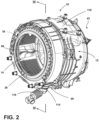
FIG. 2 is a perspective view of a tub assembly that houses a rotating drum, including an aspect of the back wall for dividing the processing space from the blower housing; -
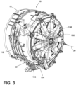
FIG. 3 is a perspective view of the tub assembly ofFIG. 2 ; -
FIG. 4 is a cross-sectional view of the tub assembly ofFIG. 2 taken along the line IV-IV; -
FIG. 5 is an exploded perspective view of the tub assembly ofFIG. 2 ; -
FIG. 6 is an enlarged cross-sectional view of the tub assembly ofFIG. 4 taken at area VI and showing the blower fan in operation; -
FIG. 7 is a cross-sectional view of the tub assembly ofFIG. 6 , and showing the blower fan in a non-rotating idle state; -
FIG. 8 is a perspective view of an aspect of the blower housing that incorporates the back wall of the drum; -
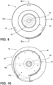
FIG. 9 is a front elevational view of the blower housing ofFIG. 8 ; -
FIG. 10 is a rear elevational view of the blower housing ofFIG. 8 ; -
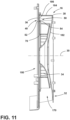
FIG. 11 is a cross-sectional view of the blower housing ofFIG. 9 taken along the line Xl-XI; -
FIG. 12 is an exploded perspective view of the blower housing ofFIG. 8 ; and -
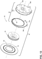
FIG. 13 is an exploded perspective view of the blower housing ofFIG. 8 . - The components in the figures are not necessarily to scale, emphasis instead being placed upon illustrating the principles described herein.
- The present illustrated embodiments reside primarily in combinations of method steps and apparatus components related to a tub assembly for a combination washing and drying appliance that incorporates a rotating drum having a back wall that separates the processing space from a blower housing that is contained in the space between the tub and the rotating drum. Accordingly, the apparatus components and method steps have been represented, where appropriate, by conventional symbols in the drawings, showing only those specific details that are pertinent to understanding the embodiments of the present disclosure so as not to obscure the disclosure with details that will be readily apparent to those of ordinary skill in the art having the benefit of the description herein. Further, like numerals in the description and drawings represent like elements.
- For purposes of description herein, the terms "upper," "lower," "right," "left," "rear," "front," "vertical," "horizontal," and derivatives thereof shall relate to the disclosure as oriented in
FIG. 1 . Unless stated otherwise, the term "front" shall refer to the surface of the element closer to an intended viewer, and the term "rear" shall refer to the surface of the element further from the intended viewer. However, it is to be understood that the disclosure may assume various alternative orientations, except where expressly specified to the contrary. It is also to be understood that the specific devices and processes illustrated in the attached drawings, and described in the following specification are simply exemplary embodiments of the inventive concepts defined in the appended claims. Hence, specific dimensions and other physical characteristics relating to the embodiments disclosed herein are not to be considered as limiting, unless the claims expressly state otherwise. - The terms "including," "comprises," "comprising," or any other variation thereof, are intended to cover a non-exclusive inclusion, such that a process, method, article, or apparatus that comprises a list of elements does not include only those elements but may include other elements not expressly listed or inherent to such process, method, article, or apparatus. An element preceded by "comprises a ... " does not, without more constraints, preclude the existence of additional identical elements in the process, method, article, or apparatus that comprises the element.
- Referring to
FIGS. 1-13 ,reference numeral 10 generally designates a tub assembly having atub 12, adrum 14, and ablower assembly 16 that is disposed between thedrum 14 and thetub 12. Thetub assembly 10 is typically incorporated as part of a combination washing anddrying appliance 18. Thisappliance 18 includes anairflow path 20 that is disposed within thetub assembly 10. Theairflow path 20 is entirely disposed within thetub 12 for movingprocess air 22 within aninterstitial space 24 defined between thetub 12 and thedrum 14. Theairflow path 20 also extends through aprocessing space 26 defined within thedrum 14. - According to various aspects of the device, the
appliance 18 includes thetub 12 that is disposed within anouter cabinet 28. Thedrum 14 is rotationally operable within thetub 12 and operates about arotational axis 30. Theairflow path 20 is defined within theinterstitial space 24 that is located between thedrum 14 and thetub 12. At least a portion of thisinterstitial space 24 defines ablower enclosure 32 that houses theblower assembly 16. Ablower fan 34 of theblower assembly 16 operates to direct theprocess air 22 through theairflow path 20. Theblower fan 34 is disposed within theblower enclosure 32 that is defined by aback wall 36, which is attached to thedrum 14, and ablower housing 38, which is attached to thetub 12. Engagement of theback wall 36 of thedrum 14 with theblower housing 38 of thetub 12 defines aslidable engagement 40 that allows thedrum 14, along with theback wall 36, to rotate relative to thetub 12 and theblower housing 38. Engagement of theback wall 36 of thedrum 14 with theblower housing 38 defines theslidable engagement 40 that is selectively sealed during operation of theblower fan 34 about therotational axis 30 to prevent aspiration ofambient air 42 into theairflow path 20. Additionally, this selectively sealed engagement can also prevent theprocess air 22 from leaving theairflow path 20 into areas that are outside of theairflow path 20 defined between thetub 12 and thedrum 14. Theblower fan 34 typically operates about the samerotational axis 30 as that of thedrum 14. Additionally, theback wall 36 is fixedly attached to thedrum 14 and theblower housing 38 is fixedly attached to thetub 12. - Referring again to
FIGS. 2-13 , theslidable engagement 40 that is formed between thedrum 14 and thetub 12 can be in the form of alabyrinth seal 50 that is formed at an interface between theback wall 36 of thedrum 14 and theblower housing 38. Thislabyrinth seal 50 provides for theslidable engagement 40 between theback wall 36 of thedrum 14 and theblower housing 38 of thetub 12. Again, theslidable engagement 40 of thelabyrinth seal 50 allows thedrum 14 to operate within thetub 12. Thislabyrinth seal 50 can include various labyrinth-type engagements that can include anannular protrusion 52 of theback wall 36 of thedrum 14 that extends toward theblower housing 38. Theblower housing 38 can include anannular channel 54 that receives theannular protrusion 52. Through this engagement between theannular protrusion 52 and theannular channel 54, thelabyrinth seal 50 allows for the rotational operation of thedrum 14 relative to thetub 12. - Additionally, during operation of the
blower fan 34, theblower fan 34 defines a high-pressure area 60 within theblower enclosure 32. This high-pressure area 60 is typically disposed near theslidable engagement 40 between theback wall 36 and theblower housing 38. Accordingly, thislabyrinth seal 50 is acted upon by the increasedair pressure 62 within the high-pressure area 60. This increasedair pressure 62 serves to increase the seal strength of thelabyrinth seal 50 such thatambient air 42 is less capable or incapable of infiltrating into theairflow path 20 via thelabyrinth seal 50. Stated another way, during operation of theblower fan 34, the increasedair pressure 62 within the high-pressure area 60 prevents aspiration ofambient air 42 into theairflow path 20 via the interface defined by thelabyrinth seal 50. Also, the slidable and sealed engagement of thelabyrinth seal 50 during operation of theblower fan 34 prevents expiration of theprocess air 22 from theairflow path 20, through thelabyrinth seal 50 and to areas external of theairflow path 20. - Referring again to
FIGS. 1-11 , a portion of theairflow path 20 extends through theinterstitial space 24 defined between thetub 12 and thedrum 14. During operation of theblower fan 34, theprocess air 22 is drawn from theprocessing space 26 of thedrum 14 and into theblower enclosure 32 through anaperture 70 defined within theback wall 36 of thedrum 14. One ormore filtration members 72 can be positioned proximate theaperture 70 of theback wall 36 to provide a filtering functionality as theprocess air 22 moves through theaperture 70 defined within theback wall 36. Thesefiltration members 72 can include perforated panels, mesh screens, and other similar filtration mechanism that can be used to separate particulate matter from the process air 22 (or other fluid) moving through theairflow path 20. In particular thefiltration member 72 filters the particulate matter as theprocess air 22 moves from theprocessing space 26 and into theblower enclosure 32. In certain aspects of the device, thefiltration member 72 can be incorporated into acontoured wall 66 that is positioned forward of theback wall 36. Thiscontoured wall 66 can includeridges 80 andvalleys 82 as well as a series ofperforated sections 74 that define thefiltration member 72. The contouredwall 66 can be attached to theback wall 36 and can rotate with thedrum 14 and theback wall 36. The contouredwall 66, in certain aspects of the device, can also be selectively operable to rotate independently with respect to theback wall 36 or in unison with theback wall 36. - In certain aspects of the device the
back wall 36 of thedrum 14 defines a portion of theprocessing space 26. In such an aspect, thefiltration member 72 can be attached to theback wall 36. Typically, thefiltration member 72 is attached to theback wall 36 as the contouredwall 66 described herein. As described herein, this contouredwall 66 can include thevarious ridges 80 andvalleys 82. Theseridges 80 andvalleys 82 are typically positioned adjacent to theback wall 36 for providing an agitating or tumbling effect on articles being processed in thedrum 14. In addition, the contouredwall 66 can include thefiltration member 72 in the form of a plurality ofperforated sections 74 that allowprocess air 22 to move therethrough, while capturing particulate material within thefiltration member 72. The contouredwall 66 and theperforated sections 74 of thefiltration member 72 allow theprocess air 22 to move through theaperture 70 defined within theback wall 36 and into theblower enclosure 32. In this aspect of the device, the contoured wall can define theprocessing space 26. In each of these aspects of the device, theback wall 36 defines theblower enclosure 32 that houses theblower fan 34. It is also contemplated that theback wall 36, in certain aspects of the device, can include theridges 80 andvalleys 82 that define theprocessing space 26. - Referring again to
FIGS. 1-7 , theairflow path 20 continues through theblower enclosure 32 that is defined between theback wall 36 of thedrum 14 and theblower housing 38 of thetub 12. Typically, thisblower housing 38 can take the form of a cochlear housing that can be used to direct theprocess air 22 from theblower fan 34 to downstream portions of theairflow path 20. These downstream portions of theairflow path 20 are typically positioned within alower section 90 of thetub 12 and beneath thedrum 14. Theprocess air 22 then moves upward to be reintroduced into theprocessing space 26 of therotating drum 14. - According to various aspects of the device, certain
heat exchange mechanisms 100 can be disposed within theairflow path 20 for heating and/or cooling theprocess air 22 as it moves through theairflow path 20. In certain aspects of the device, theseheat exchange mechanisms 100 can include heating elements, heat pump systems, air-to-air heat exchangers, condensers, combinations thereof, and other similarheat exchange mechanisms 100. - Referring again to
FIGS. 2-11 , within theairflow path 20 defined within alower section 90 of thetub 12, theheat exchange mechanism 100 can include a cooler such as an evaporator or an air-to-air heat exchanger that decreases the temperature of theprocess air 22 and, in turn, separatescondensate 110 from theprocess air 22. Thiscondensate 110 can be collected within thelower section 90 of thetub 12, such as within asump 112. Thissump 112 can be attached to anoutlet 114 that directs thiscondensate 110 to adrain 116 that is extends from thelower section 90 of thetub 12. Thedrain 116 typically includes a pump that can direct thecondensate 110 and/or wash fluid to be expelled from theappliance 18 or recirculated through a fluid delivery system. Theoutlet 114 is typically defined within anouter wall 118 of thetub 12 within thelower section 90. Thissump 112 having theoutlet 114 collects thecondensate 110 and directs thecondensate 110 to thedrain 116 for moving the capturedcondensate 110 to an external area or to a collection within theappliance 18. - Referring again to
FIGS. 1-4 , thetub assembly 10 can include afirst motor 130 that rotationally operates theblower fan 34 and asecond motor 132 that rotationally operates thedrum 14. The first andsecond motors first motor 130 is coupled to thetub 12 via aninner drive shaft 134, typically a solid shaft that extends from therear wall 182 of thetub 12 and to thedrum 14. Thesecond motor 132 is coupled with theblower fan 34 via ahollow drive tube 136 that surrounds a portion of theinner drive shaft 134.Various bearings 138 can be positioned between theinner drive shaft 134 and thehollow drive tube 136. Additionally, certainexternal bearings 138 can be positioned between thehollow drive tube 136 and thetub 12. Portions of thetub 12 can include a bearing housing that is attached or incorporated within thetub 12. - Referring again to
FIGS. 1-13 , anair handling system 150 for the combination washing and dryingappliance 18 includes thetub 12 that is disposed within thecabinet 28. Thedrum 14 includes theback wall 36. Thedrum 14 is rotationally operable within thetub 12 about therotational axis 30. Theairflow path 20 is entirely contained within thetub 12 and is defined by theinterstitial space 24 between thedrum 14 and thetub 12, as well as theprocessing space 26 contained within thedrum 14. Theblower fan 34 delivers theprocess air 22 through theairflow path 20. As described herein, theblower fan 34 is disposed between theback wall 36 of thedrum 14 and theblower housing 38 of thetub 12. Theback wall 36 rotates with thedrum 14 and is slidably engaged within theblower housing 38 that is attached to thetub 12. Thisslidable engagement 40 between theback wall 36 of thedrum 14 and theblower housing 38 of thetub 12 defines alabyrinth seal 50. Through this engagement, theblower fan 34 rotationally operates within the blower space orblower enclosure 32 defined between theback wall 36 and theblower housing 38 and contemporaneously allows theback wall 36 of thedrum 14 to rotate relative to theblower housing 38 of thetub 12. - As described herein, the
labyrinth seal 50 is disposed proximate the high-pressure area 60 of theblower enclosure 32. This high-pressure area 60 is generated during operation of theblower fan 34. During operation of theblower fan 34, theblower housing 38 and theback wall 36 are biased against one another within thelabyrinth seal 50. This biasingforce 160 is a result of the increasedair pressure 62 that is generated within the high-pressure area 60 of theblower housing 38. This increasedair pressure 62 increases the seal integrity of thelabyrinth seal 50. This increased seal integrity prevents aspiration ofambient air 42 into theairflow path 20. In certain aspects of the device, the increasedair pressure 62 can also prevent expiration ofprocess air 22 away from theairflow path 20. - According to various aspects of the device, during operation of the
blower fan 34, the increasedair pressure 62 increases the seal integrity of thelabyrinth seal 50 that is defined between theback wall 36 of thedrum 14 and theblower housing 38 of thetub 12. Thislabyrinth seal 50 includes certain sliding interface engagements such as lubricants,bearings 138, and other similar materials and mechanisms that allow slidable operation of theback wall 36 of thedrum 14 relative to theblower housing 38 of thetub 12 during operation of the blower. - During operation of the blower, a drying-function of the combination washing and drying
appliance 18 is typically being performed. During this drying-function, the drying undergoes a tumble-type operation that includes a relatively slow rotation of thedrum 14 within thetub 12. Because theblower fan 34 is operating during the drying function, thelabyrinth seal 50 has a greater seal integrity as a result of the increasedair pressure 62. Accordingly, because of the slower operation of thedrum 14 in the tumble operation, the increased seal integrity, and potentially greater friction, does not interfere with the slower rotation of thedrum 14. - During washing-type functions of the combination washing and drying
appliance 18, a rinse and spin cycle can be utilized for extracting wash fluid from articles being processed and from theprocessing space 26, generally. During this extraction function, thedrum 14 will rotate at a high rate of speed relative to theblower housing 38 and thetub 12. During this rinse and spin function, theblower fan 34 will typically be idle such that theair pressure 62 around thelabyrinth seal 50 will not be increased and the high-pressure area 60 is not formed. Accordingly, thelabyrinth seal 50 includes a typical seal integrity that allows for less friction at thelabyrinth seal 50. In turn, thedrum 14 and theback wall 36 of thedrum 14 are able to rotationally operate at a high rate of speed relative to theblower housing 38 and thetub 12 without generating unnecessary amounts of heat from friction or other surface-to-surface contact. - As described herein, the
tub 12 includes adrain 116 having anoutlet 114 that is defined within anouter wall 118 of thetub 12. Thisoutlet 114 is positioned within theairflow path 20. Accordingly, wash fluid that may accumulate within theprocessing space 26, theblower housing 38, or other portion of theairflow path 20 can be conveniently directed to thelower section 90 of thetub 12 to be directed into thedrain 116 for recycling or removal from theappliance 18. - Referring again to
FIGS. 1-13 , thelabyrinth seal 50 defined herein can include various structures that engage with one another to form thelabyrinth seal 50. These structures that form thelabyrinth seal 50 are annular in nature, such that they extend around and concentric with therotational axis 30 of theblower fan 34 and thedrum 14. In this manner, thelabyrinth seal 50 extends continuously around thisrotational axis 30 and forms the sealing engagement within thelabyrinth seal 50, as described herein. - Referring again to
FIGS. 1-13 , the combination washing and dryingappliance 18 includes thetub 12 that is disposed within theouter cabinet 28. Thedrum 14 includes theback wall 36. Thedrum 14 and theback wall 36 are attached to one another and are rotationally operable within thetub 12 about therotational axis 30. Theairflow path 20 for the combination washing and dryingappliance 18 is entirely contained within thetub 12 and is positioned within theinterstitial space 24 defined between thedrum 14 and thetub 12. Thedrain 116 is disposed within thelower section 90 of thetub 12 and theoutlet 114 for thedrain 116 is disposed within theairflow path 20 and is defined by anouter wall 118 of thetub 12. Theblower fan 34 deliversprocess air 22 through theairflow path 20 that is contained within thetub 12. Theblower fan 34 is disposed between theback wall 36 of thedrum 14 and theblower housing 38 of thetub 12. Theback wall 36 rotates with thedrum 14 and is slidably engaged with theblower housing 38 to define alabyrinth seal 50. Theblower fan 34 rotationally operates within theblower enclosure 32 defined between theback wall 36 of thedrum 14 and theblower housing 38 of thetub 12. Thisblower enclosure 32 can also be referred to as a blower space or thecochlear space 170 that is defined by theblower housing 38. Moisture, typically in the form ofcondensate 110, is collected within theairflow path 20 is directed to theoutlet 114 of thedrain 116 for recycling within a fluid delivery system of theappliance 18 or for removal or other expulsion from theappliance 18. - Referring to
FIGS. 11-13 , theblower housing 38 can contain theblower fan 34 within thecochlear space 170. In such an aspect of the device, theblower housing 38 can include anenclosure panel 180 having arear wall 182 and asidewall 184. Thesidewall 184 of theenclosure panel 180 is configured to attach to aninterface panel 186. Theinterface panel 186 can include theannular channel 54 that forms a portion of thelabyrinth seal 50. In this manner, theenclosure panel 180 and theinterface panel 186 form thecochlear space 170 within which theblower fan 34 operates. Theback wall 36 of thedrum 14, as described herein, slidably engages theinterface panel 186 of theblower housing 38. - According to various aspects of the device, use of the
labyrinth seal 50 defined between theback wall 36 of thedrum 14 and theblower housing 38 of thetub 12 forms a sealing engagement that provides for use of theairflow path 20 that is entirely contained within thetub 12. During certain aspects of the laundry cycle, such as a rinse cycle, spin cycle and other washing-type laundry functions (shown inFIG. 7 ), thelabyrinth seal 50 may allow for movement and fluid and air between theblower enclosure 32 and theprocessing space 26 via the sliding engagement. During drying-functions of a laundry cycle or sections of a laundry cycle where theblower fan 34 is in operation (shown inFIG. 6 ), the increasedair pressure 62 within theblower housing 38 creates a greater seal integrity at thelabyrinth seal 50 and seals theairflow path 20 in the area of theblower enclosure 32. This sealed and sliding engagement prevents movement ofprocess air 22 through thelabyrinth seal 50 and to areas outside of theairflow path 20. Accordingly,process air 22 moving from theprocessing space 26 and to theblower enclosure 32 is directed through, and not around, theaperture 70 defined within theback wall 36 of thedrum 14 and through the filtering mechanisms contained within theback wall 36. Moreover,ambient air 42 can be prevented from infiltrating into the airflow space through thislabyrinth seal 50. This sealing engagement is generated while also allowing rotational operation of thedrum 14 relative to thetub 12. - Because the
labyrinth seal 50 is a dynamic seal that changes depending upon whether theblower fan 34 is being operated or not, certain functions of the dryingappliance 18 are more readily operated depending upon the status of theblower fan 34. As described herein, during a rinse and spin function, and other washing-type functions, theblower fan 34 is idle and does not rotate. This normalizes the seal integrity at thelabyrinth seal 50 and allows for a more convenient high-speed rotation of thedrum 14 relative to thetub 12. When theblower fan 34 operates, such as during a drying function, the increasedair pressure 62 generated by operation of theblower fan 34 creates the high-pressure area 60 that increases the seal integrity of thelabyrinth seal 50 and prevents movement ofprocess air 22 orambient air 42 through thislabyrinth seal 50. As described herein, because thedrum 14 rotates at a slower rate of speed during the drying function, the heightened integrity of thelabyrinth seal 50 provides for the slow rotation, or (tumble) of thedrum 14 during performance of a drying function. - By using this configuration of the
back wall 36 of thedrum 14 and theblower housing 38, as well as thelabyrinth seal 50 formed therebetween, a single space can be used for theairflow path 20 as well as a space for collectingcondensate 110 and wash fluid used during operation of theappliance 18. Accordingly, greater efficiencies in the use of space are achieved that can provide for larger sizes oftubs 12 androtating drums 14, as well as more components being disposed within a similar-sizedouter cabinet 28. - The invention disclosed herein is further summarized in the following paragraphs and is further characterized by combinations of any and all of the various aspects described therein.
- According to one aspect of the present disclosure, a combination washing and drying appliance includes a tub that is disposed within a cabinet. A drum is rotationally operable within the tub about a rotational axis. An airflow path is defined within an interstitial space between the drum and the tub. A blower fan operates to direct process air through the airflow path. The blower fan is disposed within a blower enclosure that is defined by a back wall of the drum and a blower housing that is attached to the tub. Engagement of the back wall of the drum and the blower housing of the tub defines a slidable engagement that is selectively sealed during operation of the blower fan to prevent the process air from leaving the airflow path and to further prevent aspiration of ambient air to the airflow path.
- According to another aspect, the back wall rotates with the drum and the blower housing is rotationally fixed with respect to the tub.
- According to another aspect, the slidable engagement is a labyrinth seal that is formed at an interface between the back wall of the drum and the blower housing.
- According to another aspect, the blower fan and the drum rotationally operate about the rotational axis.
- According to another aspect, a first motor rotationally operates the blower fan and a second motor rotationally operates the drum.
- According to another aspect, the first motor is coupled to the blower fan via an inner drive shaft.
- According to another aspect, the second motor is coupled with the drum via a hollow drive tube that surrounds a portion of the inner drive shaft.
- According to another aspect, operation of the blower fan defines a high-pressure area that is disposed near the slidable engagement between the back wall and the blower housing.
- According to another aspect, the high-pressure area defines the slidable engagement and a sealed engagement of the labyrinth seal that prevents aspiration of the ambient air into the airflow path.
- According to another aspect, the slidable and sealed engagements of the labyrinth seal also prevents expiration of the process air away from the airflow path.
- According to another aspect, the airflow path is entirely contained within the tub.
- According to another aspect, the blower housing includes a cochlear space that directs the process air from the drum and through a portion of the airflow path that extends below the drum.
- According to another aspect of the present disclosure, a combination washing and drying appliance includes a tub that is disposed within a cabinet. A drum has a back wall and is rotationally operable within the tub about a rotational axis. An airflow path is defined within an interstitial space between the drum and the tub. A drain is disposed within a lower section of the tub. An outlet for the drain is disposed within the airflow path. A blower fan delivers process air through the airflow path that is contained within the tub. The blower fan is disposed between the back wall of the drum and a blower housing of the tub. The back wall rotates with the drum and is slidably engaged with the blower housing to define a labyrinth seal. The blower fan rotationally operates within a blower enclosure that is defined between the back wall and the blower housing. Moisture collected in the airflow path is directed to the outlet of the drain.
- According to another aspect, the labyrinth seal is disposed proximate a high-pressure area of the blower enclosure, and the high-pressure area is generated during operation of the blower fan.
- According to another aspect, operation of the blower fan, the blower housing and the back wall are biased against one another within the labyrinth seal as a result of an increased air pressure within the high-pressure area.
- According to another aspect, the increased air pressure increases a seal integrity of the labyrinth seal to prevent aspiration of ambient air into the airflow path.
- According to another aspect, the increased air pressure further increases the seal integrity of the labyrinth seal to prevent expiration of the process air from the airflow path.
- According to yet another aspect of the present disclosure, an air handling system for a laundry appliance includes a tub that is disposed within a cabinet. A drum has a back wall and is rotationally operable within the tub about a rotational axis. An airflow path is defined within an interstitial space between the drum and the tub. A blower fan delivers process air through the airflow path that is contained within the tub. The blower fan is disposed between the back wall of the drum and a blower housing of the tub. The back wall rotates with the drum and is slidably engaged with the blower housing to define a labyrinth seal. The blower fan rotationally operates within a blower enclosure that is defined between the back wall and the blower housing.
- According to another aspect, the labyrinth seal is disposed proximate a high-pressure area of the blower enclosure. The high-pressure area is generated during operation of the blower fan, and, during operation of the blower fan, the blower housing and the back wall are biased against one another within the labyrinth seal as a result of an increased air pressure within the high-pressure area.
- According to another aspect, the increased air pressure increases a seal integrity of the labyrinth seal to prevent aspiration of ambient air into the airflow path. The increased air pressure further increases the seal integrity of the labyrinth seal to prevent expiration of the process air from the airflow path.
Claims (15)
- A combination washing and drying appliance (18) comprising:a tub (12) disposed within a cabinet (28);a drum (14) that is rotationally operable within the tub (12) about a rotational axis (30), wherein an airflow path (20) is defined within an interstitial space (24) between the drum (14) and the tub (12); anda blower fan (34) that operates to direct process air (22) through the airflow path (20), the blower fan (34) disposed within a blower enclosure (32) defined by a back wall (36) of the drum (14) and a blower housing (38) that is attached to the tub (12), wherein engagement of the back wall (36) of the drum (14) and the blower housing (38) of the tub (12) defines a slidable engagement (40) that is selectively sealed during operation of the blower fan (34) to prevent the process air (22) from leaving the airflow path (20) and to further prevent aspiration of ambient air (42) to the airflow path (20).
- The combination washing and drying appliance (18) of claim 1, wherein the back wall (36) rotates with the drum (14) and the blower housing (38) is rotationally fixed with respect to the tub (12).
- The combination washing and drying appliance (18) of any one of claims 1-2, wherein the slidable engagement (40) is a labyrinth seal (50) that is formed at an interface between the back wall (36) of the drum (14) and the blower housing (38).
- The combination washing and drying appliance (18) of any one of claims 1-3, wherein the blower fan (34) and the drum (14) rotationally operate about the rotational axis (30).
- The combination washing and drying appliance (18) of any one of claims 1-4, wherein a first motor (130) rotationally operates the blower fan (34) and a second motor (132) rotationally operates the drum (14).
- The combination washing and drying appliance (18) of claim 5, wherein the first motor (130) is coupled to the blower fan (34) via an inner drive shaft (134).
- The combination washing and drying appliance (18) of claim 6, wherein the second motor (132) is coupled with the drum (14) via a hollow drive tube (136) that surrounds a portion of the inner drive shaft (134).
- The combination washing and drying appliance (18) of any one of claims 3-7, wherein operation of the blower fan (34) defines a high-pressure area (60) that is disposed near the slidable engagement (40) between the back wall (36) and the blower housing (38).
- The combination washing and drying appliance (18) of claim 8, wherein the high-pressure area (60) defines the slidable engagement (40) and a sealed engagement of the labyrinth seal (50) that prevents aspiration of the ambient air (42) into the airflow path (20).
- The combination washing and drying appliance (18) of claim 9, wherein the slidable and sealed engagements of the labyrinth seal (50) also prevents expiration of the process air (22) away from the airflow path (20).
- The combination washing and drying appliance (18) of any one of claims 1-10, wherein the blower housing (38) includes a cochlear space that directs the process air (22) from the drum (14) and through a portion of the airflow path (20) that extends below the drum (14).
- The combination washing and drying appliance (18) of any one of claims 1-11, further comprising:
a heat exchange mechanism (100) disposed within the airflow path (20), wherein the heat exchange mechanism (100) includes a cooler for separating the condensate (110) from the process air (22), the heat exchange mechanism (100) also including a heater for heating the process air (22) that is directed to a processing space (26) defined within the drum (14). - The combination washing and drying appliance (18) of claim 12, further comprising:
a drain (116) coupled with a lower section (90) of the tub (12), wherein an outlet (114) for the drain (116). - The combination washing and drying appliance (18) of any one of claims 5-13, wherein at least one of the first and second motors (130, 132) is a direct drive motor.
- The combination washing and drying appliance (18) of any one of claims 1-14, wherein the airflow path (20) is entirely contained within the tub (12).
Applications Claiming Priority (1)
| Application Number | Priority Date | Filing Date | Title |
|---|---|---|---|
| US18/075,819 US12234595B2 (en) | 2022-12-06 | 2022-12-06 | Back wall enclosure for a drum within a laundry appliance that separates a processing space from a blower housing |
Publications (2)
| Publication Number | Publication Date |
|---|---|
| EP4382655A1 true EP4382655A1 (en) | 2024-06-12 |
| EP4382655B1 EP4382655B1 (en) | 2025-09-10 |
Family
ID=89076234
Family Applications (1)
| Application Number | Title | Priority Date | Filing Date |
|---|---|---|---|
| EP23214011.1A Active EP4382655B1 (en) | 2022-12-06 | 2023-12-04 | Combination washing and drying appliance with airflow seal |
Country Status (2)
| Country | Link |
|---|---|
| US (1) | US12234595B2 (en) |
| EP (1) | EP4382655B1 (en) |
Citations (4)
| Publication number | Priority date | Publication date | Assignee | Title |
|---|---|---|---|---|
| JPS61284300A (en) * | 1985-06-12 | 1986-12-15 | 三洋電機株式会社 | Clothing dryer |
| EP0341497A1 (en) * | 1988-05-07 | 1989-11-15 | Sanyo Electric Co., Ltd. | Clothes dryer |
| CN110438725A (en) * | 2018-05-04 | 2019-11-12 | 惠而浦公司 | Combined washing and drying appliances |
| EP4089222A1 (en) * | 2021-05-10 | 2022-11-16 | Whirlpool Corporation | Combination washing and drying appliance having an airflow system contained within an outer tub |
Family Cites Families (21)
| Publication number | Priority date | Publication date | Assignee | Title |
|---|---|---|---|---|
| US2892335A (en) | 1956-04-19 | 1959-06-30 | Gen Electric | Laundry machine with forced air circulation system |
| US2940179A (en) | 1956-09-04 | 1960-06-14 | Mc Graw Edison Co | Laundry dryers |
| US3006176A (en) | 1960-06-03 | 1961-10-31 | Borg Warner | Combination washer-dryer |
| US3333346A (en) | 1965-03-30 | 1967-08-01 | Gen Motors Corp | Domestic clothes dryer |
| US4338730A (en) | 1979-08-23 | 1982-07-13 | Tokyo Shibaura Denki Kabushiki Kaisha | Dryer |
| US4665628A (en) | 1986-03-31 | 1987-05-19 | Raytheon Company | Recuperative clothes dryer with enhanced recirculation and air flow |
| JPH0767518B2 (en) | 1991-09-25 | 1995-07-26 | 三洋電機株式会社 | Clothes dryer |
| JPH078691A (en) | 1993-06-24 | 1995-01-13 | Toshiba Corp | Clothes dryer |
| JP3723689B2 (en) | 1998-09-02 | 2005-12-07 | 株式会社日立製作所 | Clothes dryer |
| KR20040100894A (en) | 2003-05-21 | 2004-12-02 | 산요덴키가부시키가이샤 | Washing machine with clothes dry function |
| JP4030523B2 (en) | 2004-05-12 | 2008-01-09 | 三洋電機株式会社 | Washing machine |
| JP3919798B2 (en) | 2005-06-28 | 2007-05-30 | シャープ株式会社 | Washing and drying machine |
| JP4911623B2 (en) | 2007-09-26 | 2012-04-04 | 三洋電機株式会社 | Dryer |
| US9109318B2 (en) | 2013-05-28 | 2015-08-18 | General Electric Company | Integration of blower with washer motor shaft or drive shaft |
| JP6363423B2 (en) | 2014-08-05 | 2018-07-25 | アクア株式会社 | Drum washing machine |
| US20190112742A1 (en) | 2017-10-17 | 2019-04-18 | Haier Us Appliance Solutions, Inc. | Fan assembly for a washing machine appliance |
| JP7141824B2 (en) | 2017-12-20 | 2022-09-26 | 三星電子株式会社 | motor |
| US11008691B2 (en) | 2018-05-04 | 2021-05-18 | Whirlpool Corporation | Laundry treating appliance having an air flow assembly |
| KR102065597B1 (en) | 2018-07-26 | 2020-01-13 | 엘지전자 주식회사 | Washing machine |
| EP3919665B1 (en) | 2020-06-03 | 2025-10-01 | HAIER Germany GmbH | Dryer for drying laundry and method of operating a dryer |
| US11795601B2 (en) | 2020-11-10 | 2023-10-24 | Whirlpool Corporation | Maximizing the dry rate of clothes tumbling combination washer/dryer with a seal |
-
2022
- 2022-12-06 US US18/075,819 patent/US12234595B2/en active Active
-
2023
- 2023-12-04 EP EP23214011.1A patent/EP4382655B1/en active Active
Patent Citations (4)
| Publication number | Priority date | Publication date | Assignee | Title |
|---|---|---|---|---|
| JPS61284300A (en) * | 1985-06-12 | 1986-12-15 | 三洋電機株式会社 | Clothing dryer |
| EP0341497A1 (en) * | 1988-05-07 | 1989-11-15 | Sanyo Electric Co., Ltd. | Clothes dryer |
| CN110438725A (en) * | 2018-05-04 | 2019-11-12 | 惠而浦公司 | Combined washing and drying appliances |
| EP4089222A1 (en) * | 2021-05-10 | 2022-11-16 | Whirlpool Corporation | Combination washing and drying appliance having an airflow system contained within an outer tub |
Also Published As
| Publication number | Publication date |
|---|---|
| EP4382655B1 (en) | 2025-09-10 |
| US20240183098A1 (en) | 2024-06-06 |
| US12234595B2 (en) | 2025-02-25 |
Similar Documents
| Publication | Publication Date | Title |
|---|---|---|
| EP2376702B1 (en) | Dryer and foreign material removing apparatus thereof | |
| KR101070536B1 (en) | Dryer and apparatus for removing lint thereof and control method thereof | |
| EP2366044B1 (en) | Dryer | |
| US9217220B2 (en) | Dryer and foreign material removing apparatus thereof | |
| KR20120134369A (en) | Clothes treating apparatus | |
| EP4089222A1 (en) | Combination washing and drying appliance having an airflow system contained within an outer tub | |
| US20180112348A1 (en) | Clothes dryer | |
| US20100146803A1 (en) | Dryer and foreign material removing apparatus thereof | |
| EP3342922A1 (en) | Dryer | |
| WO2014181493A1 (en) | Washing and drying machine | |
| CA1040418A (en) | Condenser apparatus | |
| EP4382655B1 (en) | Combination washing and drying appliance with airflow seal | |
| CN104428461A (en) | Washing and drying machine | |
| JP6111412B2 (en) | Drum washing machine | |
| EP2366828B1 (en) | Laundry dryer machine with improved condenser cooling system | |
| KR102842499B1 (en) | Clothes dryer | |
| JP2014033841A (en) | Clothes dryer | |
| US20240068152A1 (en) | Laundry appliance having an enclosed supplemental heat exchange space that surrounds a rotating drum | |
| KR101769365B1 (en) | Washing machine | |
| KR101685977B1 (en) | drying device | |
| CN1727560A (en) | Clothing drier possessing equipment for handling air | |
| CN114318803B (en) | clothes dryer | |
| EP4299813B1 (en) | Combination washing and drying laundry appliance having a filter cleaning system for removing lint during a laundry cycle | |
| US20240295066A1 (en) | Laundry appliance with automatic self-clean filter | |
| CN1312345C (en) | washer dryer |
Legal Events
| Date | Code | Title | Description |
|---|---|---|---|
| PUAI | Public reference made under article 153(3) epc to a published international application that has entered the european phase |
Free format text: ORIGINAL CODE: 0009012 |
|
| STAA | Information on the status of an ep patent application or granted ep patent |
Free format text: STATUS: THE APPLICATION HAS BEEN PUBLISHED |
|
| AK | Designated contracting states |
Kind code of ref document: A1 Designated state(s): AL AT BE BG CH CY CZ DE DK EE ES FI FR GB GR HR HU IE IS IT LI LT LU LV MC ME MK MT NL NO PL PT RO RS SE SI SK SM TR |
|
| STAA | Information on the status of an ep patent application or granted ep patent |
Free format text: STATUS: REQUEST FOR EXAMINATION WAS MADE |
|
| RAP1 | Party data changed (applicant data changed or rights of an application transferred) |
Owner name: BEKO EUROPE MANAGEMENT S.R.L. |
|
| 17P | Request for examination filed |
Effective date: 20241210 |
|
| GRAP | Despatch of communication of intention to grant a patent |
Free format text: ORIGINAL CODE: EPIDOSNIGR1 |
|
| STAA | Information on the status of an ep patent application or granted ep patent |
Free format text: STATUS: GRANT OF PATENT IS INTENDED |
|
| INTG | Intention to grant announced |
Effective date: 20250519 |
|
| P01 | Opt-out of the competence of the unified patent court (upc) registered |
Free format text: CASE NUMBER: APP_25596/2025 Effective date: 20250528 |
|
| GRAS | Grant fee paid |
Free format text: ORIGINAL CODE: EPIDOSNIGR3 |
|
| GRAA | (expected) grant |
Free format text: ORIGINAL CODE: 0009210 |
|
| STAA | Information on the status of an ep patent application or granted ep patent |
Free format text: STATUS: THE PATENT HAS BEEN GRANTED |
|
| AK | Designated contracting states |
Kind code of ref document: B1 Designated state(s): AL AT BE BG CH CY CZ DE DK EE ES FI FR GB GR HR HU IE IS IT LI LT LU LV MC ME MK MT NL NO PL PT RO RS SE SI SK SM TR |
|
| REG | Reference to a national code |
Ref country code: GB Ref legal event code: FG4D |
|
| REG | Reference to a national code |
Ref country code: CH Ref legal event code: EP |
|
| REG | Reference to a national code |
Ref country code: DE Ref legal event code: R096 Ref document number: 602023006571 Country of ref document: DE |
|
| REG | Reference to a national code |
Ref country code: IE Ref legal event code: FG4D |
|
| PG25 | Lapsed in a contracting state [announced via postgrant information from national office to epo] |
Ref country code: NO Free format text: LAPSE BECAUSE OF FAILURE TO SUBMIT A TRANSLATION OF THE DESCRIPTION OR TO PAY THE FEE WITHIN THE PRESCRIBED TIME-LIMIT Effective date: 20251210 |
|
| REG | Reference to a national code |
Ref country code: LT Ref legal event code: MG9D |
|
| PGFP | Annual fee paid to national office [announced via postgrant information from national office to epo] |
Ref country code: AT Payment date: 20260113 Year of fee payment: 3 |
|
| PG25 | Lapsed in a contracting state [announced via postgrant information from national office to epo] |
Ref country code: FI Free format text: LAPSE BECAUSE OF FAILURE TO SUBMIT A TRANSLATION OF THE DESCRIPTION OR TO PAY THE FEE WITHIN THE PRESCRIBED TIME-LIMIT Effective date: 20250910 |
|
| REG | Reference to a national code |
Ref country code: NL Ref legal event code: MP Effective date: 20250910 |
|
| PG25 | Lapsed in a contracting state [announced via postgrant information from national office to epo] |
Ref country code: HR Free format text: LAPSE BECAUSE OF FAILURE TO SUBMIT A TRANSLATION OF THE DESCRIPTION OR TO PAY THE FEE WITHIN THE PRESCRIBED TIME-LIMIT Effective date: 20250910 |
|
| PGFP | Annual fee paid to national office [announced via postgrant information from national office to epo] |
Ref country code: FR Payment date: 20251223 Year of fee payment: 3 |
|
| PG25 | Lapsed in a contracting state [announced via postgrant information from national office to epo] |
Ref country code: GR Free format text: LAPSE BECAUSE OF FAILURE TO SUBMIT A TRANSLATION OF THE DESCRIPTION OR TO PAY THE FEE WITHIN THE PRESCRIBED TIME-LIMIT Effective date: 20251211 |
|
| PG25 | Lapsed in a contracting state [announced via postgrant information from national office to epo] |
Ref country code: SE Free format text: LAPSE BECAUSE OF FAILURE TO SUBMIT A TRANSLATION OF THE DESCRIPTION OR TO PAY THE FEE WITHIN THE PRESCRIBED TIME-LIMIT Effective date: 20250910 |
|
| PG25 | Lapsed in a contracting state [announced via postgrant information from national office to epo] |
Ref country code: LV Free format text: LAPSE BECAUSE OF FAILURE TO SUBMIT A TRANSLATION OF THE DESCRIPTION OR TO PAY THE FEE WITHIN THE PRESCRIBED TIME-LIMIT Effective date: 20250910 |
|
| PG25 | Lapsed in a contracting state [announced via postgrant information from national office to epo] |
Ref country code: PL Free format text: LAPSE BECAUSE OF FAILURE TO SUBMIT A TRANSLATION OF THE DESCRIPTION OR TO PAY THE FEE WITHIN THE PRESCRIBED TIME-LIMIT Effective date: 20250910 Ref country code: BG Free format text: LAPSE BECAUSE OF FAILURE TO SUBMIT A TRANSLATION OF THE DESCRIPTION OR TO PAY THE FEE WITHIN THE PRESCRIBED TIME-LIMIT Effective date: 20250910 |
|
| PG25 | Lapsed in a contracting state [announced via postgrant information from national office to epo] |
Ref country code: RS Free format text: LAPSE BECAUSE OF FAILURE TO SUBMIT A TRANSLATION OF THE DESCRIPTION OR TO PAY THE FEE WITHIN THE PRESCRIBED TIME-LIMIT Effective date: 20251210 |
|
| PG25 | Lapsed in a contracting state [announced via postgrant information from national office to epo] |
Ref country code: ES Free format text: LAPSE BECAUSE OF FAILURE TO SUBMIT A TRANSLATION OF THE DESCRIPTION OR TO PAY THE FEE WITHIN THE PRESCRIBED TIME-LIMIT Effective date: 20250910 |
|
| REG | Reference to a national code |
Ref country code: AT Ref legal event code: MK05 Ref document number: 1835979 Country of ref document: AT Kind code of ref document: T Effective date: 20250910 |
|
| PG25 | Lapsed in a contracting state [announced via postgrant information from national office to epo] |
Ref country code: NL Free format text: LAPSE BECAUSE OF FAILURE TO SUBMIT A TRANSLATION OF THE DESCRIPTION OR TO PAY THE FEE WITHIN THE PRESCRIBED TIME-LIMIT Effective date: 20250910 |
|
| PG25 | Lapsed in a contracting state [announced via postgrant information from national office to epo] |
Ref country code: SM Free format text: LAPSE BECAUSE OF FAILURE TO SUBMIT A TRANSLATION OF THE DESCRIPTION OR TO PAY THE FEE WITHIN THE PRESCRIBED TIME-LIMIT Effective date: 20250910 |
|
| PGFP | Annual fee paid to national office [announced via postgrant information from national office to epo] |
Ref country code: DE Payment date: 20251229 Year of fee payment: 3 |
|
| PG25 | Lapsed in a contracting state [announced via postgrant information from national office to epo] |
Ref country code: AT Free format text: LAPSE BECAUSE OF FAILURE TO SUBMIT A TRANSLATION OF THE DESCRIPTION OR TO PAY THE FEE WITHIN THE PRESCRIBED TIME-LIMIT Effective date: 20250910 |
|
| PG25 | Lapsed in a contracting state [announced via postgrant information from national office to epo] |
Ref country code: RO Free format text: LAPSE BECAUSE OF FAILURE TO SUBMIT A TRANSLATION OF THE DESCRIPTION OR TO PAY THE FEE WITHIN THE PRESCRIBED TIME-LIMIT Effective date: 20250910 |
|
| PGFP | Annual fee paid to national office [announced via postgrant information from national office to epo] |
Ref country code: IT Payment date: 20251231 Year of fee payment: 3 |
|
| PG25 | Lapsed in a contracting state [announced via postgrant information from national office to epo] |
Ref country code: IS Free format text: LAPSE BECAUSE OF FAILURE TO SUBMIT A TRANSLATION OF THE DESCRIPTION OR TO PAY THE FEE WITHIN THE PRESCRIBED TIME-LIMIT Effective date: 20260110 |
|
| PG25 | Lapsed in a contracting state [announced via postgrant information from national office to epo] |
Ref country code: PT Free format text: LAPSE BECAUSE OF FAILURE TO SUBMIT A TRANSLATION OF THE DESCRIPTION OR TO PAY THE FEE WITHIN THE PRESCRIBED TIME-LIMIT Effective date: 20260112 Ref country code: CZ Free format text: LAPSE BECAUSE OF FAILURE TO SUBMIT A TRANSLATION OF THE DESCRIPTION OR TO PAY THE FEE WITHIN THE PRESCRIBED TIME-LIMIT Effective date: 20250910 |
|
| PG25 | Lapsed in a contracting state [announced via postgrant information from national office to epo] |
Ref country code: SK Free format text: LAPSE BECAUSE OF FAILURE TO SUBMIT A TRANSLATION OF THE DESCRIPTION OR TO PAY THE FEE WITHIN THE PRESCRIBED TIME-LIMIT Effective date: 20250910 Ref country code: EE Free format text: LAPSE BECAUSE OF FAILURE TO SUBMIT A TRANSLATION OF THE DESCRIPTION OR TO PAY THE FEE WITHIN THE PRESCRIBED TIME-LIMIT Effective date: 20250910 |