EP4382629A1 - Fe-based alloy, alloy member, product, and method for manufacturing alloy member - Google Patents
Fe-based alloy, alloy member, product, and method for manufacturing alloy member Download PDFInfo
- Publication number
- EP4382629A1 EP4382629A1 EP23756489.3A EP23756489A EP4382629A1 EP 4382629 A1 EP4382629 A1 EP 4382629A1 EP 23756489 A EP23756489 A EP 23756489A EP 4382629 A1 EP4382629 A1 EP 4382629A1
- Authority
- EP
- European Patent Office
- Prior art keywords
- less
- alloy
- phase
- product
- based alloy
- Prior art date
- Legal status (The legal status is an assumption and is not a legal conclusion. Google has not performed a legal analysis and makes no representation as to the accuracy of the status listed.)
- Pending
Links
Images



Classifications
-
- C—CHEMISTRY; METALLURGY
- C22—METALLURGY; FERROUS OR NON-FERROUS ALLOYS; TREATMENT OF ALLOYS OR NON-FERROUS METALS
- C22C—ALLOYS
- C22C38/00—Ferrous alloys, e.g. steel alloys
- C22C38/18—Ferrous alloys, e.g. steel alloys containing chromium
- C22C38/30—Ferrous alloys, e.g. steel alloys containing chromium with cobalt
-
- B—PERFORMING OPERATIONS; TRANSPORTING
- B22—CASTING; POWDER METALLURGY
- B22F—WORKING METALLIC POWDER; MANUFACTURE OF ARTICLES FROM METALLIC POWDER; MAKING METALLIC POWDER; APPARATUS OR DEVICES SPECIALLY ADAPTED FOR METALLIC POWDER
- B22F10/00—Additive manufacturing of workpieces or articles from metallic powder
- B22F10/20—Direct sintering or melting
- B22F10/25—Direct deposition of metal particles, e.g. direct metal deposition [DMD] or laser engineered net shaping [LENS]
-
- B—PERFORMING OPERATIONS; TRANSPORTING
- B22—CASTING; POWDER METALLURGY
- B22F—WORKING METALLIC POWDER; MANUFACTURE OF ARTICLES FROM METALLIC POWDER; MAKING METALLIC POWDER; APPARATUS OR DEVICES SPECIALLY ADAPTED FOR METALLIC POWDER
- B22F10/00—Additive manufacturing of workpieces or articles from metallic powder
- B22F10/20—Direct sintering or melting
- B22F10/28—Powder bed fusion, e.g. selective laser melting [SLM] or electron beam melting [EBM]
-
- B—PERFORMING OPERATIONS; TRANSPORTING
- B22—CASTING; POWDER METALLURGY
- B22F—WORKING METALLIC POWDER; MANUFACTURE OF ARTICLES FROM METALLIC POWDER; MAKING METALLIC POWDER; APPARATUS OR DEVICES SPECIALLY ADAPTED FOR METALLIC POWDER
- B22F10/00—Additive manufacturing of workpieces or articles from metallic powder
- B22F10/60—Treatment of workpieces or articles after build-up
- B22F10/62—Treatment of workpieces or articles after build-up by chemical means
-
- B—PERFORMING OPERATIONS; TRANSPORTING
- B22—CASTING; POWDER METALLURGY
- B22F—WORKING METALLIC POWDER; MANUFACTURE OF ARTICLES FROM METALLIC POWDER; MAKING METALLIC POWDER; APPARATUS OR DEVICES SPECIALLY ADAPTED FOR METALLIC POWDER
- B22F10/00—Additive manufacturing of workpieces or articles from metallic powder
- B22F10/60—Treatment of workpieces or articles after build-up
- B22F10/64—Treatment of workpieces or articles after build-up by thermal means
-
- B—PERFORMING OPERATIONS; TRANSPORTING
- B33—ADDITIVE MANUFACTURING TECHNOLOGY
- B33Y—ADDITIVE MANUFACTURING, i.e. MANUFACTURING OF THREE-DIMENSIONAL [3D] OBJECTS BY ADDITIVE DEPOSITION, ADDITIVE AGGLOMERATION OR ADDITIVE LAYERING, e.g. BY 3D PRINTING, STEREOLITHOGRAPHY OR SELECTIVE LASER SINTERING
- B33Y10/00—Processes of additive manufacturing
-
- B—PERFORMING OPERATIONS; TRANSPORTING
- B33—ADDITIVE MANUFACTURING TECHNOLOGY
- B33Y—ADDITIVE MANUFACTURING, i.e. MANUFACTURING OF THREE-DIMENSIONAL [3D] OBJECTS BY ADDITIVE DEPOSITION, ADDITIVE AGGLOMERATION OR ADDITIVE LAYERING, e.g. BY 3D PRINTING, STEREOLITHOGRAPHY OR SELECTIVE LASER SINTERING
- B33Y40/00—Auxiliary operations or equipment, e.g. for material handling
- B33Y40/20—Post-treatment, e.g. curing, coating or polishing
-
- B—PERFORMING OPERATIONS; TRANSPORTING
- B33—ADDITIVE MANUFACTURING TECHNOLOGY
- B33Y—ADDITIVE MANUFACTURING, i.e. MANUFACTURING OF THREE-DIMENSIONAL [3D] OBJECTS BY ADDITIVE DEPOSITION, ADDITIVE AGGLOMERATION OR ADDITIVE LAYERING, e.g. BY 3D PRINTING, STEREOLITHOGRAPHY OR SELECTIVE LASER SINTERING
- B33Y70/00—Materials specially adapted for additive manufacturing
-
- B—PERFORMING OPERATIONS; TRANSPORTING
- B33—ADDITIVE MANUFACTURING TECHNOLOGY
- B33Y—ADDITIVE MANUFACTURING, i.e. MANUFACTURING OF THREE-DIMENSIONAL [3D] OBJECTS BY ADDITIVE DEPOSITION, ADDITIVE AGGLOMERATION OR ADDITIVE LAYERING, e.g. BY 3D PRINTING, STEREOLITHOGRAPHY OR SELECTIVE LASER SINTERING
- B33Y80/00—Products made by additive manufacturing
-
- C—CHEMISTRY; METALLURGY
- C22—METALLURGY; FERROUS OR NON-FERROUS ALLOYS; TREATMENT OF ALLOYS OR NON-FERROUS METALS
- C22C—ALLOYS
- C22C33/00—Making ferrous alloys
- C22C33/02—Making ferrous alloys by powder metallurgy
- C22C33/0257—Making ferrous alloys by powder metallurgy characterised by the range of the alloying elements
- C22C33/0278—Making ferrous alloys by powder metallurgy characterised by the range of the alloying elements with at least one alloying element having a minimum content above 5%
- C22C33/0285—Making ferrous alloys by powder metallurgy characterised by the range of the alloying elements with at least one alloying element having a minimum content above 5% with Cr, Co, or Ni having a minimum content higher than 5%
-
- C—CHEMISTRY; METALLURGY
- C22—METALLURGY; FERROUS OR NON-FERROUS ALLOYS; TREATMENT OF ALLOYS OR NON-FERROUS METALS
- C22C—ALLOYS
- C22C38/00—Ferrous alloys, e.g. steel alloys
- C22C38/02—Ferrous alloys, e.g. steel alloys containing silicon
-
- C—CHEMISTRY; METALLURGY
- C22—METALLURGY; FERROUS OR NON-FERROUS ALLOYS; TREATMENT OF ALLOYS OR NON-FERROUS METALS
- C22C—ALLOYS
- C22C38/00—Ferrous alloys, e.g. steel alloys
- C22C38/04—Ferrous alloys, e.g. steel alloys containing manganese
-
- C—CHEMISTRY; METALLURGY
- C22—METALLURGY; FERROUS OR NON-FERROUS ALLOYS; TREATMENT OF ALLOYS OR NON-FERROUS METALS
- C22C—ALLOYS
- C22C38/00—Ferrous alloys, e.g. steel alloys
- C22C38/06—Ferrous alloys, e.g. steel alloys containing aluminium
-
- C—CHEMISTRY; METALLURGY
- C22—METALLURGY; FERROUS OR NON-FERROUS ALLOYS; TREATMENT OF ALLOYS OR NON-FERROUS METALS
- C22C—ALLOYS
- C22C38/00—Ferrous alloys, e.g. steel alloys
- C22C38/08—Ferrous alloys, e.g. steel alloys containing nickel
-
- C—CHEMISTRY; METALLURGY
- C22—METALLURGY; FERROUS OR NON-FERROUS ALLOYS; TREATMENT OF ALLOYS OR NON-FERROUS METALS
- C22C—ALLOYS
- C22C38/00—Ferrous alloys, e.g. steel alloys
- C22C38/14—Ferrous alloys, e.g. steel alloys containing titanium or zirconium
-
- C—CHEMISTRY; METALLURGY
- C22—METALLURGY; FERROUS OR NON-FERROUS ALLOYS; TREATMENT OF ALLOYS OR NON-FERROUS METALS
- C22C—ALLOYS
- C22C38/00—Ferrous alloys, e.g. steel alloys
- C22C38/16—Ferrous alloys, e.g. steel alloys containing copper
-
- C—CHEMISTRY; METALLURGY
- C22—METALLURGY; FERROUS OR NON-FERROUS ALLOYS; TREATMENT OF ALLOYS OR NON-FERROUS METALS
- C22C—ALLOYS
- C22C38/00—Ferrous alloys, e.g. steel alloys
- C22C38/18—Ferrous alloys, e.g. steel alloys containing chromium
- C22C38/22—Ferrous alloys, e.g. steel alloys containing chromium with molybdenum or tungsten
-
- C—CHEMISTRY; METALLURGY
- C22—METALLURGY; FERROUS OR NON-FERROUS ALLOYS; TREATMENT OF ALLOYS OR NON-FERROUS METALS
- C22C—ALLOYS
- C22C38/00—Ferrous alloys, e.g. steel alloys
- C22C38/18—Ferrous alloys, e.g. steel alloys containing chromium
- C22C38/24—Ferrous alloys, e.g. steel alloys containing chromium with vanadium
-
- C—CHEMISTRY; METALLURGY
- C22—METALLURGY; FERROUS OR NON-FERROUS ALLOYS; TREATMENT OF ALLOYS OR NON-FERROUS METALS
- C22C—ALLOYS
- C22C38/00—Ferrous alloys, e.g. steel alloys
- C22C38/18—Ferrous alloys, e.g. steel alloys containing chromium
- C22C38/36—Ferrous alloys, e.g. steel alloys containing chromium with more than 1.7% by weight of carbon
-
- C—CHEMISTRY; METALLURGY
- C23—COATING METALLIC MATERIAL; COATING MATERIAL WITH METALLIC MATERIAL; CHEMICAL SURFACE TREATMENT; DIFFUSION TREATMENT OF METALLIC MATERIAL; COATING BY VACUUM EVAPORATION, BY SPUTTERING, BY ION IMPLANTATION OR BY CHEMICAL VAPOUR DEPOSITION, IN GENERAL; INHIBITING CORROSION OF METALLIC MATERIAL OR INCRUSTATION IN GENERAL
- C23C—COATING METALLIC MATERIAL; COATING MATERIAL WITH METALLIC MATERIAL; SURFACE TREATMENT OF METALLIC MATERIAL BY DIFFUSION INTO THE SURFACE, BY CHEMICAL CONVERSION OR SUBSTITUTION; COATING BY VACUUM EVAPORATION, BY SPUTTERING, BY ION IMPLANTATION OR BY CHEMICAL VAPOUR DEPOSITION, IN GENERAL
- C23C28/00—Coating for obtaining at least two superposed coatings either by methods not provided for in a single one of groups C23C2/00 - C23C26/00 or by combinations of methods provided for in subclasses C23C and C25C or C25D
- C23C28/04—Coating for obtaining at least two superposed coatings either by methods not provided for in a single one of groups C23C2/00 - C23C26/00 or by combinations of methods provided for in subclasses C23C and C25C or C25D only coatings of inorganic non-metallic material
-
- B—PERFORMING OPERATIONS; TRANSPORTING
- B22—CASTING; POWDER METALLURGY
- B22F—WORKING METALLIC POWDER; MANUFACTURE OF ARTICLES FROM METALLIC POWDER; MAKING METALLIC POWDER; APPARATUS OR DEVICES SPECIALLY ADAPTED FOR METALLIC POWDER
- B22F2301/00—Metallic composition of the powder or its coating
- B22F2301/35—Iron
-
- B—PERFORMING OPERATIONS; TRANSPORTING
- B22—CASTING; POWDER METALLURGY
- B22F—WORKING METALLIC POWDER; MANUFACTURE OF ARTICLES FROM METALLIC POWDER; MAKING METALLIC POWDER; APPARATUS OR DEVICES SPECIALLY ADAPTED FOR METALLIC POWDER
- B22F2304/00—Physical aspects of the powder
- B22F2304/10—Micron size particles, i.e. above 1 micrometer up to 500 micrometer
-
- B—PERFORMING OPERATIONS; TRANSPORTING
- B22—CASTING; POWDER METALLURGY
- B22F—WORKING METALLIC POWDER; MANUFACTURE OF ARTICLES FROM METALLIC POWDER; MAKING METALLIC POWDER; APPARATUS OR DEVICES SPECIALLY ADAPTED FOR METALLIC POWDER
- B22F2998/00—Supplementary information concerning processes or compositions relating to powder metallurgy
- B22F2998/10—Processes characterised by the sequence of their steps
-
- B—PERFORMING OPERATIONS; TRANSPORTING
- B22—CASTING; POWDER METALLURGY
- B22F—WORKING METALLIC POWDER; MANUFACTURE OF ARTICLES FROM METALLIC POWDER; MAKING METALLIC POWDER; APPARATUS OR DEVICES SPECIALLY ADAPTED FOR METALLIC POWDER
- B22F2999/00—Aspects linked to processes or compositions used in powder metallurgy
Definitions
- the present invention relates to an Fe-based alloy, an alloy member, a product, and a method for manufacturing the alloy member.
- hot work tool steel such as SKD8, which is regulated by JIS G 4404, with high strength at elevated temperatures, or high-speed tool steel such as SKH51, which is regulated by JIS G 4403, have been used conventionally.
- JIS G 4404 high strength at elevated temperatures
- high-speed tool steel such as SKH51, which is regulated by JIS G 4403, have been used conventionally.
- set-in fatigue, wearing, fracture, and heat cracks can easily occur.
- Patent Document 1 discloses a high-speed tool steel that is fabricated by powder metallurgy and includes, by mass ratio, 0.8 - 3.95% of C, 30 - 50% of a total amount of W and Mo, in which the mass of Mo is twice the mass of W, 3.0 - 5.0% of Cr, 1.0 - 10.0% of V, 5 - 15% of Co with the remainder made up of Fe and unavoidable impurities.
- the high-speed tool steel disclosed in Patent Document 1 includes a lot of residual carbide at the time of quenching, and the residual carbide is finely dispersed uniformly onto a base.
- the high-speed tool steel has high wear resistance along with high toughness, thereby having high durability against cutting.
- Patent Document 1 Japanese Unexamined Patent Application Publication No. S51-072906 ( JP-A- S51-072906 )
- a first aspect of the present invention is an Fe-based alloy that has an alloy structure including C, Cr, W, Mo, and V, with the remainder made up of Fe and unavoidable impurities, and including a Fe-BCC phase and a W-Mo-concentrated phase.
- the Fe-BCC phase includes 3% or more and 7% or less of C, 2% or more and 6% or less of Cr, 0.5% or more and 8% or less of W, 3% or more and 8% or less of Mo, 2% or more and 20% or less of V, and 60% or more and 90% or less of Fe
- the W-Mo-concentrated phase includes 5% or more and 13% or less of C, 2% or more and 12% or less of Cr, 7% or more and 17% or less of W, 11% or more and 22% or less of Mo, 3% or more and 19% or less of V, and 40% or more and 50% or less of Fe.
- the W-Mo-concentrated phase is formed so as to surround the Fe-BCC phase.
- the Fe-based alloy as a whole includes, by mass, 0.3% or more and 2.8% or less of C, 3.0% or more and 10.0% or less of Cr, 1.5% or more and 10.5% or less of W, 2.0% or more and 9.0% or less of Mo, 1.0% or more and 8.0% or less of V, and the remainder made up of Fe and unavoidable impurities.
- the Fe-based alloy further includes either one of or both of Si and Mn, in which Si is included 1.0% or less by mass and Mn is included 0.1% or more and 1.0% or less by mass.
- the Fe-based alloy as a whole further includes, by mass, 10.5% or less of Co
- the Fe-BCC phase further includes 9% or more and 13% or less of Co
- the W-Mo-concentrated phase further includes 6% or more and 11% or less of Co.
- the W-Mo-concentrated phase is formed by including a lamellar structure or substantially ring-shaped depositions.
- an alloy having excellent mechanical properties can be obtained. Also, since the alloy includes the Fe-BCC phase and the W-Mo-concentrated phase, in which the W-Mo-concentrated phase is formed so as to surround the Fe-BCC phase, the relatively softer Fe-BCC phase wears down primarily when a metal die, for example, is slid, leaving the worn parts being formed into dimple shapes. The dimple-shaped parts hold lubricant oil or the like, thereby preventing occurrence of adhesive wear. Thus, the alloy has an excellent wear resistant property.
- Such the alloy can be obtained by using an additive manufacturing method (hereinafter referred as a metal additive manufacturing or, simply, an additive manufacturing), in which desirable composition of metal powder is formed into the alloy.
- a metal additive manufacturing or, simply, an additive manufacturing
- the W-Mo-concentrated phase forms the lamellar structure or the substantially ring-shaped depositions, and thus the high mechanical properties and the wear resistant property can be obtained with more certainty.
- a second aspect of the present invention is an alloy member that includes at least partly the Fe-based alloy according to the first aspect of the present invention.
- the Fe-based alloy is formed on a surface of a base material of the alloy member, a thickness of a top layer from an interface between the base material and the Fe-based alloy to a surface of the Fe-based alloy is between 0.1 mm and 2 mm, hardness of the top layer is 700 HV or more, and an average crystal grain diameter of the Fe-BCC phase is 3.0 ⁇ m or more.
- the alloy member may include any one of a nitride layer, a compound layer, and a ceramic coating layer on the surface of the Fe-based alloy.
- an alloy member having excellent mechanical properties as well as an excellent wear resistant property can be obtained.
- an alloy layer that is made of the Fe-based alloy according to the first aspect of the present invention on the surface of the base material, a member having a wear-resistant surface can be obtained. Also, even if a part of the surface is damaged, for example, the alloy layer can be formed again by deposition on the damaged part only. Thus, repairing is easy and the alloy member having excellent mechanical properties as well as an excellent wear resistant property can be obtained.
- nitride layer or the like on the surface can provide higher durability.
- a third aspect of the present invention is a product that includes at least partly the alloy member according to the second aspect of the present invention.
- a product having excellent mechanical properties as well as an excellent wear resistant property can be obtained.
- Such the product are a hot stamping die, a cold forging die, and a cold pressing die.
- a fourth aspect of the present invention is a method for manufacturing an alloy member.
- the method includes using alloy powder including, by mass, 0.3% or more and 2.8% or less of C, 3.0% or more and 10.0% or less of Cr, 1.5% or more and 10.5% or less of W, 2.0% or more and 9.0% or less of Mo, 1.0% or more and 8.0% of less of V, and the remainder made up of Fe and unavoidable impurities, forming a solidified layer by melting and solidifying the alloy powder by applying an electron beam or a laser beam onto the alloy powder, forming another solidified layer onto the solidified layer, and repeating the above steps to obtain the alloy member having a layered structure.
- the alloy powder may further include Co and it is preferable that the alloy powder includes 10.5% or less of Co by mass.
- the method may further include a surface treatment step for performing a surface treatment on the obtained alloy member.
- the surface treatment step may be a film formation using a nitride treatment or a PVD method.
- an alloy member having excellent mechanical properties as well as an excellent wear resistant property can be obtained.
- the additional surface treatment such as forming a nitride layer on a surface, can further enhance the wear resistance of the alloy member.
- the present invention can provide an Fe-based alloy having excellent mechanical properties as well as an excellent wear resistant property, an alloy member, a product, and a method for manufacturing the alloy member.
- An Fe-based alloy according to the present embodiment has an alloy structure including C, Cr, W, Mo, and V, with the remainder made up of Fe and unavoidable impurities, and including a Fe-BCC phase and a W-Mo-concentrated phase.
- the Fe-BCC phase includes 3 - 7% of C, 2 - 6% of Cr, 0.5 - 8% of W, 3 - 8% of Mo, 2 - 20% of V, and 60 - 90% of Fe
- the W-Mo-concentrated phase includes 5 - 13% of C, 2 - 12% of Cr, 7 - 17% of W, 11 - 22% of Mo, 3 - 19% of V, and 40 - 50% of Fe.
- the W-Mo-concentrated phase is formed so as to surround the Fe-BCC phase.
- the Fe-based alloy according to the present embodiment further includes, by mass, 10.5% or less of Co
- the Fe-BCC phase includes 9% or more and 13% or less of Co
- the W-Mo-concentrated phase includes 6% or more and 11% or less of Co.
- 3% or more and 11% or less is more preferable, and 6% or more and 10% or less of Co is further more preferable.
- the W-Mo-concentrated phase is formed continuously in substantial ring shapes or the W-Mo-concentrated phase is divided but arranged in the substantial ring shapes, a structure in which the W-Mo-concentrated phase surrounds the Fe-BCC phase can be obtained.
- the structure is microscopically heterogeneous, that is, the structure has a distribution of W-Mo-concentrated phase and Fe-BCC phase that are not completely mixed with each other.
- the relatively softer Fe-BCC phase wears down primarily before the relatively harder W-Mo-concentrated phase, leaving Fe-BCC phase surrounded by the W-Mo-concentrated phase being worn down into dimple shapes.
- the dimple-shaped parts hold lubricant oil, which can improve the wear resistance.
- such dimple-shaped parts are formed dispersedly, thereby preventing occurrence of adhesive wear.
- the Fe-based alloy as a whole includes, by mass, 0.3% or more and 2.8% or less of C, 3.0% or more and 10.0% or less of Cr, 1.5% or more and 10.5% or less of W, 2.0% or more and 9.0% or less of Mo, 1.0% or more and 8.0% of less of V, 10.5% or less of Co, and the remainder made up of Fe and unavoidable impurities.
- the Fe-based alloy further includes either one of or both of Si and Mn, in which Si is included 1.0% or less by mass and Mn is included 0.1% or more and 1.0% or less by mass.
- Si is expected to improve oxidation resistance and preferably included within the above range when taking workability into consideration.
- Mn is expected to have effects on improving wear resistance and quenching performance as well on reducing embrittlement. On the other hand, taking influence of the embrittlement due to quench cracks or residual ⁇ into consideration, Mn is preferably included within the above range.
- an average crystal grain diameter of the Fe-BCC phase is preferably 3.0 ⁇ m or more, or, more preferably, 5.0 ⁇ m or more.
- Fe-BCC phase includes Fe in the BCC phase with C, Cr, W, Mo, V, and Co being included within the above-mentioned composition range. A method for calculating the average crystal grain diameter of the Fe-BCC phase will be described below.
- the W-Mo-concentrated phase is a region in which W and Mo are more concentrated than in the Fe-BCC phase.
- the W-Mo-concentrated phase may preferably form mesh-like lamellar structures or depositions.
- the mesh-like lamellar structures or the depositions include a lot of W and Mo in particular.
- a lower limit of a total amount of W and Mo (W + Mo) is preferably 15% or more, more preferably 20% or more, or further more preferably 26% or more.
- an upper limit of the total amount of W and Mo (W + Mo) is preferably 60.0% or less, more preferably 52.0% or less, or furthermore preferably 45.0% or less.
- a lower limit of a ratio of the total amount of W and Mo (W + Mo) to Fe ((W + Mo) / Fe) in the W-Mo-concentrated phase is preferably 0.25 or more, and more preferably 0.60 or more.
- An upper limit of the ratio of the total amount of W and Mo (W + Mo) to Fe ((W + Mo) / Fe) is preferably 2.50 or less, and more preferably 2.40 or less.
- the Fe-BCC phase is formed within a region that is surrounded by the mesh-like lamellar structure or the substantially ring-shaped depositions of the W-Mo-concentrated phase. That is, the W-Mo-concentrated phase is formed continuously in substantial ring shapes so as to surround the Fe-BCC phase (and other phases).
- the W-Mo-concentrated phase formed continuously in the substantial ring shapes is formed into substantial ring shapes having a circle equivalent diameter of approximately 10 ⁇ m in many cases, and it is preferable that the circle equivalent diameter is between 5 ⁇ m and 20 ⁇ m.
- a lower limit of the average crystal grain diameter of the Fe-BCC phase formed within the region surrounded by the W-Mo-concentrated phase is 3.0 ⁇ m, preferably 4.8 mm, and more preferably 5.0 ⁇ m. Also, although an upper limit thereof is not particularly specified, it is preferable that the upper limit is 8.0 ⁇ m or less, preferably 6.5 ⁇ m or less, and more preferably 5.5 ⁇ m or less.
- the W-Mo-concentrated phase may not be completely continuous but may be divided.
- depositions having a grain diameter of approximately1 ⁇ m are formed being arranged in substantial ring shapes with circle equivalent diameters of 5 - 20 ⁇ m.
- the W-Mo-concentrated phase is to be temporarily a solid solution with the base, and carbide forming elements such as V, W, and Mo are deposited as carbide during a cooling process or a tempering process after the quenching.
- carbide forming elements such as V, W, and Mo are deposited as carbide during a cooling process or a tempering process after the quenching.
- the above depositions with the grain diameter of approximately 1 ⁇ m are supposed to be a carbide phase of the deposited carbide.
- the W-Mo-concentrated phase may be formed being arranged in a predetermined direction forming a substantial ring shape as a whole, instead of being uniformly distributed. Such the form is referred to as "formed so as to surround the Fe-BCC phase" or “formed in substantial ring shapes".
- the region surrounded by the W-Mo-concentrated phase may include minute depositions having grain diameters of approximately 0.1 - 0.5 ⁇ m.
- the carbide phase mentioned above is a region that includes more concentrated V, Mo, and W than in the Fe-BCC phase, with a lot of C.
- One example of composition of the carbide phase is, by mass, 10% - 16% of C, 1% - 5% of Cr, 8% - 25% of W, 13% - 23% of Mo, 25% - 35% of V, 0% - 5% of Co, and 3% - 35% of Fe.
- Each structure can be evaluated by using an energy-dispersive X-ray spectroscopy (EDS) and an electron back scattering diffraction (EBSD) that are attached to a scanning electron microscope (SEM).
- EDS energy-dispersive X-ray spectroscopy
- EBSD electron back scattering diffraction
- SEM scanning electron microscope
- Conditions for the analysis may be, for example, an acceleration voltage of 15 kV for the SEM, a working distance between an objective lens and a top surface of an observing sample of 10 mm, and an observation magnification of 3000 times.
- a method for evaluating an element distribution using EDS is to obtain an element-mapping image by surface analysis on the same visual field used for the above SEM.
- targeted elements may be, for example, eight elements: C, Co, Cr, Fe, Mo, O, V, and W.
- the Fe-BCC phase can also be analyzed in the same way as above.
- a method for evaluating the phases using EBSD is to obtain a phase mapping image of a visual field of 200 ⁇ m by 200 ⁇ m with a magnification of 400 times.
- the above-mentioned average crystal grain diameter of the Fe-BCC phase can be calculated as below.
- the phase map obtained by EBSD e.g., an RGB image of 200 ⁇ m by 200 ⁇ m
- the phase map obtained by EBSD is sectioned according to each color (red, green, and blue) to extract Fe-BCC parts only. Noises of the image are filtered and removed, and the image is converted into a monochrome binary image, which is then black/white inverted (e.g., an originally red section (Fe-BCC phase) will be shown as black).
- the Fe-BCC phase part is segmented by using Watershed Algorithm, and diameters of the crystal grains forming the Fe-BCC phase within the segmented view fields are calculated to find the average value. In this way, the average crystal grain diameter forming the Fe-BCC phase (the average crystal grain diameter of the Fe-BCC phase) can be calculated.
- the phase map obtained by EBSD is sectioned into a red section (Fe-BCC phase), a blue section (mainly Fe-FCC phase), and a green section (a section that is neither Fe-BCC phase nor Fe-FCC phase, which will be referred to as a "zero solution section” hereafter).
- a red section Fe-BCC phase
- a blue section mainly Fe-FCC phase
- a green section a section that is neither Fe-BCC phase nor Fe-FCC phase, which will be referred to as a "zero solution section” hereafter.
- ratios of Fe-BCC phase and deposited carbide within the structure can be found.
- the Fe-BCC phase is shown as white.
- the blue section and the green section is then shown as white.
- a total area is a total of areas of the red section, the blue section, and the green section, and a value found by dividing the red section (Fe-BCC phase) by the total area can be expressed as an area ratio.
- the zero solution section can be shown by taking off the images of the sectioned blue section from the black/white inverted image.
- the zero solution section is neither Fe-BCC phase nor Fe-FCC phase, and corresponds to the deposited carbide section.
- an average area of the deposited carbide section in the visual field is calculated, and a circle equivalent diameter of the area is then calculated to find a circle equivalent average grain diameter of the deposited carbide in the Fe-BCC phase.
- Unavoidable impurities refer to very small amounts of impurities that are technically difficult to be removed.
- the unavoidable impurities may have been mixed into raw materials or generated due to reactions or the like with various members that come into contact with the raw materials during manufacturing processes.
- specific examples of the unavoidable impurities are Al, Cu, N, Ni, O, P, S, and Ti.
- P, S, O, and N are impurities that are to be restricted in particular.
- P is preferably 0.03% or less
- S is preferably less than 0.003%
- O is preferably 0.02% or less
- N is preferably 0.05% or less.
- less content of such the unavoidable impurities is preferable, and 0% of the unavoidable impurities is even better.
- the Fe-based alloy according to the present embodiment is manufactured by using alloy powder, forming a solidified layer by melting and solidifying the alloy powder by applying an electron beam or a laser beam onto the alloy powder, forming a new solidified layer onto the solidified layer, and repeating the above operations to obtain an additively-manufactured alloy member. That is, the alloy is manufactured using a so-called additive manufacturing method.
- the alloy powder is Fe-based alloy powder including the above-mentioned predetermined composition of C, Cr, W, Mo, V, and Co with the remainder made up of Fe and unavoidable impurities.
- predetermined amounts of supply material of each of the elements are measured and are mixed together to produce raw powder.
- the raw powder is then used to obtain atomized powder.
- the raw powder is loaded into a crucible and melted at high frequency.
- the melted alloy is dropped out of a nozzle at a bottom of the crucible, and then high-pressure Argon is sprayed to the alloy so as to produce gas-atomized powder.
- the gas-atomized powder is then classified to obtain the alloy powder.
- the additive manufacturing method is a method for making a product by additive formation, in which fusion and solidification are repeated on individual powders.
- a grain diameter of the alloy powder is less than 5 ⁇ m, it is difficult to obtain a volume required for one fusion-solidification, which makes it difficult to produce a decent additively-manufactured product.
- the grain diameter of the alloy powder is more than 250 ⁇ m, the volume required for one fusion-solidification is too large, which also makes it difficult to produce a decent additively-manufactured product.
- the grain diameter of the alloy powder is preferably between 5 ⁇ m and 250 ⁇ m, and more preferably between 10 ⁇ m and 150 ⁇ m.
- Spherical powders that can be obtained from a gas-atomizing method are preferable.
- a grain size distribution may be measured by using a laser diffraction grain size distribution measuring apparatus, for example.
- the grain diameter is preferably between 10 ⁇ m and 53 ⁇ m in a selective laser melting (SLM) method; and the grain diameter is more preferably between 45 ⁇ m and 105 ⁇ m in an electron beam melting (EBM) method. Also, the grain diameter is preferably between 53 ⁇ m and 150 ⁇ m, or more preferably between 53 ⁇ m and 106 ⁇ m, in a laser metal deposition (LMD) method.
- SLM selective laser melting
- EBM electron beam melting
- the grain diameter is preferably between 53 ⁇ m and 150 ⁇ m, or more preferably between 53 ⁇ m and 106 ⁇ m, in a laser metal deposition (LMD) method.
- LMD laser metal deposition
- D50 is preferably 50 ⁇ m - 100 ⁇ m, and more preferably 70 ⁇ m - 80 ⁇ m.
- the Fe-based alloy powder preferably includes, by mass, 0.3 - 2.8% of C, 3.0 - 10.0% of Cr, 1.5 - 10.5% of W, 2.0 - 9.0% of Mo, 1.0 - 8.0% of V, and the remainder made up of Fe. It is more preferable that the Fe-based alloy powder further includes either or both of Si and Mn. If Co is included, the Fe-based alloy powder may include 10.5% or less of Co.
- the Fe-based alloy powder including, by mass, 0.3 - 2.8% of C, more than 0% and 1.0% or less of Si, 0.1 - 1.0% of Mn, 3.0 - 10.0% of Cr, 1.5 - 10.5% of W, 2.0 - 9.0% of Mo, 1.0 - 8.0% of V, and the remainder made up of Fe and unavoidable impurities may be used.
- the Fe-based alloy powder may include Co, and, in such the case, the Fe-based alloy powder including, by mass, 0.3 - 2.8% of C, more than 0% and 1.0% or less of Si, 0.1 - 1.0% of Mn, 3.0 - 10.0% of Cr, 1.5 - 10.5% of W, 2.0 - 9.0% of Mo, 1.0 - 8.0% of V, more than 0% and 10.5% or less of Co, and the remainder made up of Fe and unavoidable impurities may be used.
- the composition of the alloy powder can be analyzed by using, for example, a high-frequency inductive coupling plasma (ICP) emission analysis method.
- ICP inductive coupling plasma
- additive manufacturing additive manufacturing methods for metal materials (referred to as "additive manufacturing” in the present invention), such as a powder bed fusion (PBF) method and a directed energy deposition (DED) method, are also applicable.
- PPF powder bed fusion
- DED directed energy deposition
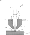
- FIG. 1 is a view showing a schematic structure of an additive manufacturing device 1 for additive manufacturing using the directed energy deposition method with a laser as a heat source.
- the additive manufacturing device 1 mainly includes a powder delivery nozzle 3, a focusing lens 5, a protector lens 7, and so on. Alloy powder 11 is fed into the powder delivery nozzle 3 and is sprayed together with argon gas to a tip end of the powder delivery nozzle 3.
- a laser beam 9 that is emitted from a laser oscillator, of which an illustration is omitted, is condensed by the focusing lens 5 and irradiated to a proximity of a tip end part of the powder delivery nozzle 3.
- the protector lens 7 is provided on a lower part of the focusing lens 5.
- the powder delivery nozzle 3 is moved in relation to a base plate 17 (in a direction A in FIG. 1 ) while feeding the alloy powder 11 over the base plate 17.
- the laser beam 9 condensed by the focusing lens 5 is irradiated onto the fed alloy powder 11, which then melts and forms a molten pool 13.
- the molten pool 13 is solidified so that a product 15 (the Fe-based alloy) can be formed.
- the directed energy deposition method is a method for manufacturing an alloy member (a product) having a layered structure by spraying alloy powder while being moved over a base material, forming a solidified layer by melting and solidifying the alloy powder by applying an electron beam or a laser beam onto the sprayed alloy powder, forming another solidified layer onto the formed solidified layer, and repeating the above steps. More specifically, by using a three-dimensional additive manufacturing apparatus, a base plate or a surface of a product is melted rapidly by laser irradiation, raw material powder is fed into the molten pool formed by the fusion, which is then solidified by rapid cooling, and such a series of processes is repeated to produce the product.
- the product formed on the base plate is the Fe-based alloy according to the present embodiment. Conditions for the additive manufacturing are determined accordingly taking the grain diameter and composition of the raw powder, a size, a shape, and properties of the product, productivity, etc. into consideration. For the alloy according to the present embodiment, the conditions can be selected within the following ranges.
- a thickness of one layer for the additive manufacturing is 0.1 - 1.0 mm or more preferably 0.4 - 0.5 mm, for example.
- a thickness of a first layer of the Fe-based alloy that is formed on a surface of a base material (the base plate) (a thickness from an interface of the base material to the surface of the first layer of the Fe-based alloy including a diffusion layer in a proximity of the interface) is 0.1 - 1 mm, and a total thickness from the interface of the base material to the surface of the Fe-based alloy (a thickness including the diffusion layer in the proximity of the interface) is 0.1 - 2 mm.
- a beam diameter of the laser is preferably approximately 3 mm at an emission position.
- a laser power is preferably 1500 - 2500 W.
- a laser scanning speed is preferably 500 - 1000 mm/min.
- An amount of powder feed is preferably 10 - 20 g/min.
- An energy density (an energy density of a heat source: J/mm) that is to be input by the laser emission for rapid fusion of the raw material is preferably 90 - 300 J/mm, or more preferably within a range of 180 - 240 J/mm. If the energy density is too small, a defect rate may rise and, furthermore, the fed powder may not melt, which makes it harder to maintain the shape of the product. Meanwhile, if the energy density is too large, a wide range of the base plate or the product, with a center at the laser emission position, may melt, which also makes it harder to maintain the shape of the product.
- the alloy according to the present embodiment can be used as being molded without any heat treatments. However, if the costs etc. are within permissible ranges, an additional heat treatment may be performed. For the heat treatment, either one of or both of quenching treatment and tempering treatment may be performed. Nevertheless, it is preferable to perform the tempering treatment only, without the quenching treatment at a high temperature.
- Conditions for the heat treatment are, for example, in a case of the quenching treatment, holding at a temperature of 1180 - 1220 °C for 10 - 60 minutes and then cooling in oil or water. It is more preferable to cool in the oil to prevent distortion and quench cracks. Quenching and cooling using a salt bath may also be performed.
- the tempering treatment is a heat treatment process in which the alloy is to be kept at 400 °C or more and 700 °C or less, and, for example, the alloy is preferably maintained at a temperature of 560 - 580 °C for 2 - 6 hours and then cooled in the air.
- a surface treatment may be applied to the obtained alloy member.
- a surface treatment process for applying the surface treatment to the alloy member includes, for example, a film formation on the top surface of the Fe-based alloy using a nitride treatment or a PVD method for forming a nitride layer, a compound layer, or a ceramic coating layer. If the surface treatment is to be performed, any one or more of the nitride layer, the compound layer, and the ceramic coating layer may be chosen.
- Hardness of the top layer of the alloy member can be evaluated by Vickers hardness HV (hereinafter, referred to as "the hardness").
- the hardness is desirably 350 HV or more, preferably 500 HV or more, more preferably 700 HV or more, further preferably 800 HV or more, and furthermore preferably 900 HV or more.
- 350 HV or more, or more preferably 500 HV or more can be obtained.
- 700 HV or more, more preferably 800 HV or more, and further preferably 900 HV or more can be obtained.
- an indentation load for a Vickers indenter is 0.5 kg
- a retention time for indentation is 10 seconds
- the hardness is found from a length of a diagonal of an impression formed on the measuring surface due to indentation of the indenter.
- products that include at least partly the alloy member obtained as above are not particularly limited, especially favorable examples thereof are a hot stamping die, a cold forging die, and a cold pressing die. In such cases, even if a part of a surface of a metal die, for example, is damaged, repairing is easy since the alloy layer of the present invention can be formed by deposition only on the damaged part.
- the Fe-based alloy here according to the present embodiment has excellent mechanical properties as well as an excellent wear resistant property with no adhesion.
- predetermined amounts of supply material of each of the elements are measured and are mixed together to produce raw powder.
- the raw powder is then loaded into a crucible and melted at high frequency in a vacuum.
- the melted alloy is dropped out of a nozzle of 5 mm diameter at a bottom of the crucible, and then high-pressure Argon is sprayed to the alloy so as to produce gas-atomized powder.
- the gas-atomized powder is then classified to obtain iron based (Fe-based) alloy powder (raw powder) of 53 - 106 ⁇ m and 71 ⁇ m at D50.
- the compositions of the obtained iron based alloy powder are shown in Table 1 and Table 2.
- the raw powder is fed to a molten pool formed by laser emission on a base plate and melted and solidified rapidly to fabricate a product having a width of 3 mm, a length of 80 mm, and a lamination height of approximately 10 mm.
- the conditions for the additive manufacturing are as follows.
- maraging steel YAG 300 by Proterial, Ltd. (YAG is a registered trademark of Proterial, Ltd.)
- the conditions for the additive manufacturing are:
- the products with and without heat treatments are evaluated.
- the heat treatments for the evaluation are: tempering only; quenching only; and tempering + quenching.
- the product being left as is after molding (no heat treatment) is referred to as F1
- the product treated with tempering only is referred to as F2
- the product treated with quenching only is referred to as F3
- the product treated with quenching and tempering is referred to as F4.
- the product is held at 1200 °C for 0.5 hours and then cooled in oil in the quenching treatment; and the product is held at 560 °C for 4 hours and then cooled in the air in the tempering treatment.
- the products of the Fe-based alloy according to the present embodiment are obtained after such the heat treatments.
- Each working example of the obtained Fe-based alloy products F1 - F4 is observed under an SEM and EDS and evaluated.
- a test piece for the observation is prepared by cutting a part of the product into a small piece and embedded within resin and polishing a cut face of the embedded product to a mirror finish.
- An observation magnification is 3000 times.
- an element mapping image is obtained by using an EDS on the same visual field of the SEM image with a magnification of 3000 times.
- the analyzed elements are eight elements: C, Co, Cr, Fe, Mo, O, V, and W.
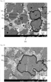
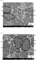
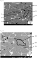
- FIG. 2A shows the product F1 without any heat treatments (no heat treatment)
- FIG. 2B shows the product F2 with the tempering heat treatment
- FIG. 2C shows the product F3 with only the quenching heat treatment
- FIG. 2D shows the product F4 with the quenching + tempering heat treatment.
- FIG. 2E shows a structure of a comparison alloy having the same composition that is produced by press forging, in which powders are sintered in a conventional powder metallurgy, with heat treatments (a sample treated with quenching and tempering; hereinafter, the press-forged material will be referred to as "F0").
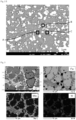
- FIG. 3 shows examples of mapping of element-mapping images (W, Mo, Fe, Cr) obtained for the product F1.
- the visual field area of each of the element-mapping images is 46 ⁇ m by 35 ⁇ m and the magnification is 3000 times.
- mesh-like lamellar structures 50 exist in the product F1, which is left as is without the heat treatments after being molded, and in the product F2, which is treated with only the tempering treatment after being molded.
- FIG. 3 showing the element-mapping images, it is also found that the structures including Mo and W form the mesh-like lamellar structures.
- the mesh-like lamellar structures and gray-colored regions 52 that are surrounded by the W-Mo-concentrated phases can be observed, it is impossible to define that the gray-colored regions 52 are all Fe-BCC phases.
- the crystal grain diameter forming the Fe-BCC phase is to be calculated by the above-mentioned method.
- the mesh-like lamellar structures are observed as striped patterns. From the element-mapping images shown in FIG. 3 , it is found that the mesh-like lamellar structure 50 observed as striped-patterns includes Fe, Mo, and W, and that the lamellar structure 50 can be observed as mesh-like forms since a part including a relatively low concentration of Fe element and a relatively high concentration of Mo and W elements is arranged adjacent to a part including a relatively high concentration of Fe element and a relatively low concentration of Mo and W elements. It is also found that the lamellar structure 50 is a W-Mo-concentrated phase, in which W and Mo are more concentrated than in parts other than the lamellar structure.
- minute depositions 56 having grain diameters of approximately 0.1 - 0.5 ⁇ m are found in the lamellar structure, i.e. the Fe-BCC phase 52 (inside a black frame in the drawing) surrounded by the W-Mo-concentrated phase. It is also found, from the element-mapping images shown in FIG. 3 , that such the depositions also include Mo and W.
- the depositions 54 having grain diameters of approximately 1 ⁇ m are arranged in ring shapes having circle equivalent diameters of 5 ⁇ m - 20 ⁇ m.
- the element-mapping images for the product F3 and the product F4 are obtained, and it is found from the element-mapping images that the deposition 54 arranged in the ring shapes is the W-Mo-concentrated phase including Mo and W.
- the minute depositions 56 having grain diameters of approximately 0.1 - 0.5 ⁇ m are found inside the Fe-BCC phase 52 (inside a black frame in the drawing) surrounded by the depositions 54 having grain diameters of approximately 1 ⁇ m, and it is found from the element-mapping images that such the depositions also include Mo and W.
- Table 3 shows composition of each phase of the product F1 with no heat treatment.
- the Fe-BCC phase is analyzed at a section A
- the W-Mo-concentrated phase is analyzed at a section B
- carbide is analyzed at a section C.
- the W-Mo-concentrated phase (the section B) of the product F1 includes 15.6% of W and 14.5% of Mo, and a total amount of W and Mo (W + Mo) is 30.1%.
- a ratio of the total amount of W and Mo to Fe ((W + Mo) / Fe) in the concentrated phase is 0.67.
- the Fe-BCC phase mainly includes Fe and also includes Cr, W, Mo, V, Co, C, and so on within predetermined ranges. Electron diffraction patterns generated at the time of emitting electron beams to the surface of the product samples are measured by using EBSD, which can show that the Fe-BCC phase has a BCC structure.
- Table 4 shows composition of each phase of the press-forged material F0.
- the Fe-BCC phase is analyzed at a section A
- the W-Mo-concentrated phase is analyzed at a section B
- carbide is analyzed at a section C.
- the W-Mo-concentrated phase (the section B) of the press-forged material F0 includes 30.5% of W and 22.6% of Mo, and a total amount of W and Mo (W + Mo) is 53.1%.
- the amount of Fe is 22.1%
- a ratio of the total amount of W and Mo to Fe ((W + Mo) / Fe) in the concentrated phase is 2.40.
- the composition of the W-Mo-concentrated phase is largely different from that of the products F1 - F4. That is, in the press-forged material F0, although the phase in which W and Mo are concentrated exists, the W-Mo-concentrated phase of the press-forged material F0 includes less Fe and more W and Mo than the products F1 - F4.
- the W-Mo-concentrated phase of the product F1 includes 5.2% of V
- the W-Mo-concentrated phase of the press-forged material F0 includes 8.2% of V
- the press-forged material F0 has a higher concentration of V. It is estimated from the above that carbide formation is more accelerated in the W-Mo-concentrated phase of the press-forged material F0 than in the W-Mo-concentrated phase of the product F1 with no heat treatment.
- the W-Mo-concentrated phase of the press-forged material F0 is harder than the W-Mo-concentrated phase of the product F1 with no heat treatment, for example.
- the hard W-Mo-concentrated phases are distributed uniformly with the Fe-BCC phases.
- the average crystal grain diameter of the Fe-BCC phase is evaluated.
- the average crystal grain diameter of the Fe-BCC phase for each of F1 - F4 and the press-forged material F0 is calculated by using the above method. The results are shown in Table 5.
- the average crystal grain diameter of the Fe-BCC phase is 5. 28 ⁇ m for the product F1 with no heat treatment, 5.33 ⁇ m for the product F2 with the tempering treatment, 4.65 ⁇ m for the product F3 with the quenching treatment, and 4.57 ⁇ m for the product F4 with the quenching and tempering treatments.
- the average crystal grain diameter of the Fe-BCC phase is 5.17 ⁇ m for the press-forged material F0. [Table 5] No.
- Fe-BCC phase Ratio (%) Average Crystal Grain Diameter of Fe-BCC phase ( ⁇ m) Deposited Carbide Ratio (%) Circle Equivalent Average Grain Diameter of Deposited Carbide ( ⁇ m) F1 45.5 5.28 1.18 1.23 F2 45.0 5.33 0.55 1.17 F3 44.8 4.65 1.05 1.07 F4 44.8 4.57 0.44 1.08 F0 45.4 5.17 0.66 1.10
- a structure is to be micronized and homogenized.
- a press-forged material is obtained by sintering powders followed by press forging and heat treatment so as to avoid weight segregation, etc. and to obtain a uniform structure.
- the method as above, it is possible to obtain a structure in which the Fe-BCC phase is relatively small and the W-Mo-concentrated phase and the Fe-BCC phase are uniformly dispersed in a microscopic way.
- the W-Mo-concentrated phase is formed continuously in substantial ring shapes like a lamellar structure, or the W-Mo-concentrated phase is divided but yet arranged in substantial ring shapes.
- a structure in which the W-Mo-concentrated phase surrounds the Fe-BCC phase can be obtained.
- the structure is microscopically heterogeneous (the structure has a distribution of W-Mo-concentrated phase and Fe-BCC phase that are not completely mixed with each other).
- the relatively softer Fe-BCC phase wears down primarily before the relatively harder W-Mo-concentrated phase, and the Fe-BCC phase surrounded by the W-Mo-concentrated phase wears out into dimple shapes having a circle equivalent diameter of 3.0 ⁇ m or more.
- the dimple-shaped parts hold lubricating oil, and this can improve wear resistance.
- such the dimple-shaped parts are formed dispersedly, thereby preventing occurrence of adhesive wear.
- the press-forged material F0 has high hardness as a whole as mentioned above.
- the W-Mo-concentrated phase and the Fe-BCC phase are dispersed uniformly and thus wearing progresses substantially uniformly and simultaneously as a whole.
- dimples or the like may not be generated, which may lead to a grease shortage and adhesion.
- adhesion and the like can be prevented efficiently.
- Hardness of the obtained Fe-based alloy products F1 - F4 is measured by using a Vickers hardness measuring device. Conditions for the measurement are: an indentation load for a Vickers indenter is 0.5 kg, a retention time for indentation is 10 seconds, and the hardness is found from a length of a diagonal of an impression formed on the measuring surface due to indentation of the indenter. The number of measurement points is 5 and an average value is calculated. Table 6 shows the results and FIG. 4 shows a comparison with the press-forged material F0. [Table 6] No. Quenching Tempering Hardness (HV) F1 - - 916 F2 - Done 944 F3 Done - 983 F4 Done Done 946 F0 Done Done 1055
- the product F1 which is left as is without the heat treatments after being molded, is found to have high hardness of 916 HV. This may be due to effects of the mesh-like lamellar structure. Also, it is found that the product F2 with only the tempering treatment after molding has hardness of 944 HV, the product F3 with the quenching treatment after molding has hardness of 983 HV, and the product F4 with the quenching and tempering treatments after molding has hardness of 946 HV. Although the press-forged material F0 with the quenching and tempering treatments has the highest hardness, the hardness drops to a half or less thereof if the quenching and tempering treatments are not performed onto the press-forged material. Thus, it can be said that the products have higher hardness than the press-forged material. As above, in the present embodiment, the sufficient hardness of 900 HV or more can be obtained in any of the cases, with or without the heat treatments.
- the product F1 and the product F2 have the mesh-like lamellar structures being formed, and are expected to have high toughness. Also, as shown in FIG. 2C and FIG. 2D , in the product F3 and the product F4, the ring-shaped depositions 54 including Mo and W exist, and thus the Fe-BCC phase and the depositions 54 are unevenly distributed. As a result, hard parts and relatively softer parts exist together in the structure of the products F3 and F4, and thus high toughness can also be expected as in the products F1 and F2.
- Co is not always necessary. Inclusion of a predetermined amount of Co can provide high mechanical properties without heat treatments. However, in cases in which Co is not included, as will be described below in Experiment 2, sufficient mechanical properties can be obtained by performing heat treatments such as quenching.
- a product is fabricated by using iron-based alloy powders having an alloy composition as shown in Table 7.
- predetermined amounts of supply material of each of the elements are measured and are mixed together to produce raw powder.
- the raw powder is then loaded into a crucible and melted at high frequency in a vacuum.
- the melted alloy is dropped out of a nozzle of 5 mm diameter at a bottom of the crucible, and then high-pressure Argon is sprayed to the alloy so as to produce gas-atomized powder.
- the gas-atomized powder is then classified to obtain iron based (Fe-based) alloy powder of 53 - 106 ⁇ m and 73 ⁇ m at D50.
- Co is considered to be included as an unavoidable impurity.
- Table 7 (mass%) C Si Mn Cr W Mo V Co Fe 1.30 0.62 0.27 4.99 2.95 5.94 3.81 0.21 Bal.
- the raw powder is fed to a molten pool formed by laser emission on a base plate and melted and solidified rapidly to fabricate a product having a width of 3 mm, a length of 80 mm, and a lamination height of approximately 10 mm.
- the conditions for the additive manufacturing are the same as in above-mentioned Experiment 1.
- maraging steel YAG 300 by Proterial, Ltd. (YAG is a registered trademark of Proterial,Ltd.) is used.
- the products with and without heat treatments are evaluated.
- the heat treatments for the evaluation are: tempering only; quenching only; and tempering + quenching.
- the product being left as is after molding (without the heat treatments) is referred to as F11
- the product treated with tempering only is referred to as F12
- the product treated with quenching only is referred to as F13
- the product treated with quenching and tempering is referred to as F14.
- the heat treatments of the products similarly to the conditions in Experiment 1, the product is held at 1200 °C for 0.5 hours and then cooled in oil in the quenching treatment; and the product is held at 560 °C for 4 hours and then cooled in the air in the tempering treatment.
- Each of the obtained Fe-based alloy products F11 - F14 is observed under an SEM and EDS and evaluated.
- a test piece for the observation is prepared by cutting a part of the product into a small piece and embedded within resin, and polishing a cut face of the embedded product to a mirror finish.
- An observation magnification is 3000 times.
- an element mapping image is obtained by using an EDS on the same visual field of the SEM image with a magnification of 3000 times.
- the analyzed elements are eight elements: C, Co, Cr, Fe, Mo, O, V, and W.
- FIG. 5A shows the product F11 without any heat treatments (no heat treatment)
- FIG. 5B shows the product F12 with the tempering heat treatment
- FIG. 5C shows the product F13 with the quenching heat treatment
- FIG. 5D shows the product F14 with the quenching + tempering heat treatment.
- FIG. 5E shows a structure of a comparison alloy having the same composition that is produced by press forging, in which powders are sintered in a conventional powder metallurgy, with heat treatments (a sample treated with quenching and tempering; hereinafter, the press-forged material will be referred to as F01).
- FIG. 6 shows examples of mapping of element-mapping images (W, Mo, Fe, Cr) obtained for the product F11.
- the visual field area of each of the element-mapping images is 46 ⁇ m by 35 ⁇ m and the magnification is 3000 times.
- the crystal grain diameter forming the Fe-BCC phase is calculated by using the above-mentioned method. Also, as shown in FIG. 5A and FIG. 5B , it is found that, from the SEM images, mesh-like lamellar structures 50 exist in the product F11, which is left as is without the heat treatments after being molded, and in the product F12, which is treated with only the tempering treatment after being molded.
- the mesh-like lamellar structure 50 includes Fe, Mo, and W, and the lamellar structure 50 can be observed as mesh-like forms since a part including a relatively low concentration of Fe element and a relatively high concentration of Mo and W elements is arranged adjacent to a part including a relatively high concentration of Fe element and a relatively low concentration of Mo and W elements. It is also found that the lamellar structure 50 is a W-Mo-concentrated phase, in which W and Mo are more concentrated than in parts other than the lamellar structure. Looking at the element mapping images shown in FIG. 6 , it is also found that the structures including Mo and W are formed as the lamellar structures or in mesh-like forms.
- FIG. 5C which is the SEM image of the product F13 that is treated with the quenching treatment after being molded
- FIG. 5D which is the SEM image of the product F14 that is treated with the quenching and tempering treatments after being molded
- the depositions 54 having grain diameters of approximately 1 ⁇ m - 2 ⁇ m are arranged in ring shapes having circle equivalent diameters of 5 ⁇ m - 20 ⁇ m.
- the deposition 54 is the W-Mo-concentrated phase including Mo and W.
- the minute depositions 56 having grain diameters of approximately 0.1 - 0.5 ⁇ m exist, and it is found from the results of EDS surface analysis image that such the depositions also include Mo and W.
- Table 8 shows composition of each phase of the product F11 as an example.
- the Fe-BCC phase is analyzed at a section A
- the W-Mo-concentrated phase is analyzed at a section B
- carbide is analyzed at a section C.
- the W-Mo-concentrated phase (the section B) of the product F11 includes 7.9% of W and 17.4% of Mo, and a total amount of W and Mo (W + Mo) is 25.3%.
- the amount of Fe is 43.0%
- a ratio of the total amount of W and Mo to Fe ((W + Mo) / Fe) in the concentrated phase is 0.59.
- the Fe-BCC phase mainly includes Fe and also includes Cr, W, Mo, V, Co, C, and so on within predetermined ranges. Electron diffraction patterns generated at the time of emitting electron beams to the surface of the product samples are measured by using EBSD, which can show that the Fe-BCC phase is in a BCC structure.
- Table 9 shows composition of each phase of the press-forged material F01.
- the Fe-BCC phase is analyzed at a section A
- the W-Mo-concentrated phase is analyzed at a section B
- carbide is analyzed at a section C.
- the W-Mo-concentrated phase (the section B) of the press-forged material F01 includes 6.3% of W and 10.6% of Mo, and a total amount of W and Mo (W + Mo) is 16.9%.
- the amount of Fe is 48.1%, a ratio of the total amount of W and Mo to Fe ((W + Mo) / Fe) in the concentrated phase is 0.35.
- the Fe-BCC phase has approximately the same composition as that of the working example products
- the composition of the W-Mo-concentrated phase of the press-forged material F01 is different from that of the products F11.
- the W-Mo-concentrated phase of the press-forged material F01 includes more Fe and less W and Mo than the products F11.
- the W-Mo-concentrated phase of the press-forged material F01 is harder than, for example, the W-Mo-concentrated phase of the product F11 with no heat treatment.
- the hard W-Mo-concentrated phases are distributed uniformly with the Fe-BCC phases.
- the average crystal grain diameter of the Fe-BCC phase is evaluated.
- the average crystal grain diameter of the Fe-BCC phase for each of F11 - F14 and the press-forged material F01 is calculated by using the above method. The results are shown in Table 10.
- the average crystal grain diameter of the Fe-BCC phase is 5.34 ⁇ m for the product F11 with no heat treatment, 5.18 ⁇ m for the product F12 with the tempering treatment, 5.05 ⁇ m for the product F13, and 4.84 ⁇ m for the product F14.
- the average crystal grain diameter of the Fe-BCC phase is 4.62 ⁇ m for the press-forged material F01.
- a ratio of the deposited carbide in F12 - F14 is 0.6% or more and 2.4% or less.
- a ratio of the Fe-BCC phase in F11 - F14 is 45.0% or more, and a ratio of the deposited carbide deposited in the Fe-BCC phase is 0.5% ore more.
- No. Fe-BCC phase Ratio (%) Average Crystal Grain Diameter of Fe-BCC phase ( ⁇ m) Deposited Carbide Ratio (%) Circle Equivalent Average Grain Diameter of Deposited Carbide ( ⁇ m) F11 45.4 5.34 0.11 1.12 F12 45.3 5.18 1.45 1.35 F13 45.1 5.05 2.36 1.22 F14 45.1 4.84 0.66 1.10 F01 44.8 4.62 1.95 1.16
- a structure is to be micronized and homogenized.
- a press-forged material is obtained by sintering powders followed by press forging and heat treatment so as to avoid weight segregation and to obtain a uniform structure.
- the method as above, it is possible to obtain a structure in which the Fe-BCC phase is relatively small and the W-Mo-concentrated phase and the Fe-BCC phase are uniformly dispersed in a microscopic way.
- the W-Mo-concentrated phase is formed continuously in substantial ring shapes (a lamellar structure), or the W-Mo-concentrated phase is divided but yet arranged in substantial ring shapes.
- a structure in which the W-Mo-concentrated phase surrounds the Fe-BCC phase can be obtained.
- the structure is microscopically heterogeneous (the structure has a distribution of W-Mo-concentrated phase and Fe-BCC phase that are not completely mixed with each other).
- the relatively softer Fe-BCC phase wears down primarily before the relatively harder W-Mo-concentrated phase, and the Fe-BCC phase surrounded by the W-Mo-concentrated phase wears out into dimple shapes having a circle equivalent diameter of 4.8 ⁇ m or more.
- the dimple-shaped parts hold oil, and this can improve wear resistance.
- such the dimple-shaped parts are formed dispersedly, thereby preventing occurrence of adhesive wear.
- the press-forged material F01 has high hardness as a whole.
- the W-Mo-concentrated phase and the Fe-BCC phase are dispersed and thus wearing progresses substantially uniformly and simultaneously as a whole.
- dimples or the like many not occur, which may lead to an oil film shortage and adhesion.
- adhesion and the like can be prevented efficiently.
- Hardness of the obtained Fe-based alloy products is measured by using a Vickers hardness measuring device. Conditions for the measurement are: an indentation load for a Vickers indenter is 0.5 kg, a retention time for indentation is 10 seconds, and the hardness is found from a length of a diagonal of an impression formed on the measuring surface due to indentation of the indenter. The number of measurement points is 5 and an average value thereof is calculated. Table 11 shows the results. [Table 11] No. Quenching Tempering Hardness (HV) F11 - - 360 F12 - Done 837 F13 Done - 804 F14 Done Done 748 F01 Done Done 907
- the product F11 which is left as is without the heat treatments after being molded, has hardness of 360 HV
- the product F12 with only the tempering treatment after molding has hardness of 837 HV
- the product F13 with the quenching treatment after molding has hardness of 804 HV
- the product F14 with the quenching and tempering treatments after molding has hardness of 748 HV.
- the product F11 which is left as is without the heat treatments after being molded
- the product F12 which is treated with only the tempering treatment after molding
- the ring-shaped depositions 54 including Mo and W exist, and thus the Fe-BCC phase and the depositions 54 are unevenly distributed.
- hard parts and relatively softer parts exist together in the structure, and thus high toughness can also be expected as in the products F1 and F2.
- Co is not always necessary. Inclusion of Co of a predetermined amount can provide high mechanical properties without heat treatments. However, in cases in which Co is not included, sufficient mechanical properties can be obtained by performing heat treatments such as quenching.
Landscapes
- Chemical & Material Sciences (AREA)
- Engineering & Computer Science (AREA)
- Materials Engineering (AREA)
- Mechanical Engineering (AREA)
- Metallurgy (AREA)
- Organic Chemistry (AREA)
- Manufacturing & Machinery (AREA)
- Chemical Kinetics & Catalysis (AREA)
- Physics & Mathematics (AREA)
- General Chemical & Material Sciences (AREA)
- Thermal Sciences (AREA)
- Plasma & Fusion (AREA)
- Inorganic Chemistry (AREA)
- Powder Metallurgy (AREA)
Abstract
Description
- The present invention relates to an Fe-based alloy, an alloy member, a product, and a method for manufacturing the alloy member.
- For hot precision press working tools such as punching tools or metal dies, hot work tool steel such as SKD8, which is regulated by JIS G 4404, with high strength at elevated temperatures, or high-speed tool steel such as SKH51, which is regulated by JIS G 4403, have been used conventionally. However, with the above materials, set-in fatigue, wearing, fracture, and heat cracks can easily occur.
- For example,
Patent Document 1 discloses a high-speed tool steel that is fabricated by powder metallurgy and includes, by mass ratio, 0.8 - 3.95% of C, 30 - 50% of a total amount of W and Mo, in which the mass of Mo is twice the mass of W, 3.0 - 5.0% of Cr, 1.0 - 10.0% of V, 5 - 15% of Co with the remainder made up of Fe and unavoidable impurities. The high-speed tool steel disclosed inPatent Document 1 includes a lot of residual carbide at the time of quenching, and the residual carbide is finely dispersed uniformly onto a base. Thus, the high-speed tool steel has high wear resistance along with high toughness, thereby having high durability against cutting. - [Patent Document 1]
Japanese Unexamined Patent Application Publication No. S51-072906 JP-A- S51-072906 - In the high-speed tool steel of
Patent Document 1, since an alloy is formed by powder metallurgy, precipitation or segregation etc. of primary crystals may hardly occur compared to a common case in which molten metal is solidified, and thus a uniform structure can be easily formed both microscopically and macroscopically. In general, the uniform structure is effective for mechanical properties, and a wear resistant property can also be gained by the uniform dispersion of carbide. However, when used for metal dies or the like, adhesive wearing of slid faces thereof, in particular, may occur and thus higher wear resistance has been expected. - It is an object of the present invention to provide an Fe-based alloy having excellent mechanical properties as well as an excellent wear resistant property, an alloy member, a product, and a method for manufacturing the alloy member.
- To achieve the above object, a first aspect of the present invention is an Fe-based alloy that has an alloy structure including C, Cr, W, Mo, and V, with the remainder made up of Fe and unavoidable impurities, and including a Fe-BCC phase and a W-Mo-concentrated phase. By mass, the Fe-BCC phase includes 3% or more and 7% or less of C, 2% or more and 6% or less of Cr, 0.5% or more and 8% or less of W, 3% or more and 8% or less of Mo, 2% or more and 20% or less of V, and 60% or more and 90% or less of Fe, and the W-Mo-concentrated phase includes 5% or more and 13% or less of C, 2% or more and 12% or less of Cr, 7% or more and 17% or less of W, 11% or more and 22% or less of Mo, 3% or more and 19% or less of V, and 40% or more and 50% or less of Fe. The W-Mo-concentrated phase is formed so as to surround the Fe-BCC phase.
- It is preferable that the Fe-based alloy as a whole includes, by mass, 0.3% or more and 2.8% or less of C, 3.0% or more and 10.0% or less of Cr, 1.5% or more and 10.5% or less of W, 2.0% or more and 9.0% or less of Mo, 1.0% or more and 8.0% or less of V, and the remainder made up of Fe and unavoidable impurities.
- It is preferable that the Fe-based alloy further includes either one of or both of Si and Mn, in which Si is included 1.0% or less by mass and Mn is included 0.1% or more and 1.0% or less by mass.
- It is preferable that the Fe-based alloy as a whole further includes, by mass, 10.5% or less of Co, the Fe-BCC phase further includes 9% or more and 13% or less of Co, and the W-Mo-concentrated phase further includes 6% or more and 11% or less of Co.
- It is preferable that the W-Mo-concentrated phase is formed by including a lamellar structure or substantially ring-shaped depositions.
- According to the first aspect of the present invention, an alloy having excellent mechanical properties can be obtained. Also, since the alloy includes the Fe-BCC phase and the W-Mo-concentrated phase, in which the W-Mo-concentrated phase is formed so as to surround the Fe-BCC phase, the relatively softer Fe-BCC phase wears down primarily when a metal die, for example, is slid, leaving the worn parts being formed into dimple shapes. The dimple-shaped parts hold lubricant oil or the like, thereby preventing occurrence of adhesive wear. Thus, the alloy has an excellent wear resistant property.
- Such the alloy can be obtained by using an additive manufacturing method (hereinafter referred as a metal additive manufacturing or, simply, an additive manufacturing), in which desirable composition of metal powder is formed into the alloy.
- Also, the W-Mo-concentrated phase forms the lamellar structure or the substantially ring-shaped depositions, and thus the high mechanical properties and the wear resistant property can be obtained with more certainty.
- A second aspect of the present invention is an alloy member that includes at least partly the Fe-based alloy according to the first aspect of the present invention.
- It is preferable that the Fe-based alloy is formed on a surface of a base material of the alloy member, a thickness of a top layer from an interface between the base material and the Fe-based alloy to a surface of the Fe-based alloy is between 0.1 mm and 2 mm, hardness of the top layer is 700 HV or more, and an average crystal grain diameter of the Fe-BCC phase is 3.0 µm or more.
- The alloy member may include any one of a nitride layer, a compound layer, and a ceramic coating layer on the surface of the Fe-based alloy.
- According to the second aspect of the present invention, an alloy member having excellent mechanical properties as well as an excellent wear resistant property can be obtained.
- Also, by forming an alloy layer that is made of the Fe-based alloy according to the first aspect of the present invention on the surface of the base material, a member having a wear-resistant surface can be obtained. Also, even if a part of the surface is damaged, for example, the alloy layer can be formed again by deposition on the damaged part only. Thus, repairing is easy and the alloy member having excellent mechanical properties as well as an excellent wear resistant property can be obtained.
- Also, further forming the nitride layer or the like on the surface can provide higher durability.
- A third aspect of the present invention is a product that includes at least partly the alloy member according to the second aspect of the present invention.
- According to the third aspect of the present invention, a product having excellent mechanical properties as well as an excellent wear resistant property can be obtained.
- Favorable examples of such the product are a hot stamping die, a cold forging die, and a cold pressing die.
- A fourth aspect of the present invention is a method for manufacturing an alloy member. The method includes using alloy powder including, by mass, 0.3% or more and 2.8% or less of C, 3.0% or more and 10.0% or less of Cr, 1.5% or more and 10.5% or less of W, 2.0% or more and 9.0% or less of Mo, 1.0% or more and 8.0% of less of V, and the remainder made up of Fe and unavoidable impurities, forming a solidified layer by melting and solidifying the alloy powder by applying an electron beam or a laser beam onto the alloy powder, forming another solidified layer onto the solidified layer, and repeating the above steps to obtain the alloy member having a layered structure.
- Also, the alloy powder may further include Co and it is preferable that the alloy powder includes 10.5% or less of Co by mass.
- The method may further include a surface treatment step for performing a surface treatment on the obtained alloy member. The surface treatment step may be a film formation using a nitride treatment or a PVD method.
- According to the fourth aspect of the present invention, an alloy member having excellent mechanical properties as well as an excellent wear resistant property can be obtained.
- The additional surface treatment, such as forming a nitride layer on a surface, can further enhance the wear resistance of the alloy member.
- The present invention can provide an Fe-based alloy having excellent mechanical properties as well as an excellent wear resistant property, an alloy member, a product, and a method for manufacturing the alloy member.
-
-
FIG. 1 is a view illustrating a schematic structure of a laser additive manufacturing method. -
FIG. 2A is a photograph of a structure of an alloy member of the present invention after laser additive manufacturing. -
FIG. 2B is a photograph of the structure of the alloy member inFIG. 2A after tempering. -
FIG. 2C is a photograph of the structure of the alloy member inFIG. 2A after quenching. -
FIG. 2D is a photograph of the structure of the alloy member inFIG. 2C after tempering. -
FIG. 2E is a photograph of a structure of a press-forged material F0 after tempering. -
FIG. 3 is an element-mapping image of the alloy member of the present invention after the laser additive manufacturing. -
FIG. 4 is a graph showing HV0.5 of each alloy member. -
FIG. 5A is a photograph of a structure of an alloy member of another embodiment of the present invention after laser additive manufacturing. -
FIG. 5B is a photograph of the structure of the alloy member inFIG. 5A after tempering. -
FIG. 5C is a photograph of the structure of the alloy member inFIG. 5A after quenching. -
FIG. 5D is a photograph of the structure of the alloy member inFIG. 5C after tempering. -
FIG. 5E is a photograph of a structure of a press-forged material F01 after quenching and tempering. -
FIG. 6 is an element-mapping image of the alloy member of the present invention after the laser additive manufacturing. - Hereinafter, an embodiment of the present invention will be described. Firstly, an Fe-based alloy will be described, and then an additive manufacturing method will be described. In the descriptions hereinafter, "%" will refer to "mass percent". Also, in the present description, the numerical value range presented by using "-" will refer to a range that includes numerical values specified before and after "-", representing a lower limit value and an upper limit value of the range, respectively.
- An Fe-based alloy according to the present embodiment has an alloy structure including C, Cr, W, Mo, and V, with the remainder made up of Fe and unavoidable impurities, and including a Fe-BCC phase and a W-Mo-concentrated phase. By mass, the Fe-BCC phase includes 3 - 7% of C, 2 - 6% of Cr, 0.5 - 8% of W, 3 - 8% of Mo, 2 - 20% of V, and 60 - 90% of Fe, and the W-Mo-concentrated phase includes 5 - 13% of C, 2 - 12% of Cr, 7 - 17% of W, 11 - 22% of Mo, 3 - 19% of V, and 40 - 50% of Fe. The W-Mo-concentrated phase is formed so as to surround the Fe-BCC phase.
- Also, it is preferable that the Fe-based alloy according to the present embodiment further includes, by mass, 10.5% or less of Co, the Fe-BCC phase includes 9% or more and 13% or less of Co, and the W-Mo-concentrated phase includes 6% or more and 11% or less of Co. Also, 3% or more and 11% or less is more preferable, and 6% or more and 10% or less of Co is further more preferable.
- For the Fe-based alloy according to the present embodiment, since the W-Mo-concentrated phase is formed continuously in substantial ring shapes or the W-Mo-concentrated phase is divided but arranged in the substantial ring shapes, a structure in which the W-Mo-concentrated phase surrounds the Fe-BCC phase can be obtained. In this way, the structure is microscopically heterogeneous, that is, the structure has a distribution of W-Mo-concentrated phase and Fe-BCC phase that are not completely mixed with each other. However, when such the structure happens to be a slid face, the relatively softer Fe-BCC phase wears down primarily before the relatively harder W-Mo-concentrated phase, leaving Fe-BCC phase surrounded by the W-Mo-concentrated phase being worn down into dimple shapes. However, the dimple-shaped parts hold lubricant oil, which can improve the wear resistance. In addition, such dimple-shaped parts are formed dispersedly, thereby preventing occurrence of adhesive wear.
- Also, it is preferable that the Fe-based alloy as a whole includes, by mass, 0.3% or more and 2.8% or less of C, 3.0% or more and 10.0% or less of Cr, 1.5% or more and 10.5% or less of W, 2.0% or more and 9.0% or less of Mo, 1.0% or more and 8.0% of less of V, 10.5% or less of Co, and the remainder made up of Fe and unavoidable impurities. It is also preferable that the Fe-based alloy further includes either one of or both of Si and Mn, in which Si is included 1.0% or less by mass and Mn is included 0.1% or more and 1.0% or less by mass. Si is expected to improve oxidation resistance and preferably included within the above range when taking workability into consideration. Mn is expected to have effects on improving wear resistance and quenching performance as well on reducing embrittlement. On the other hand, taking influence of the embrittlement due to quench cracks or residual γ into consideration, Mn is preferably included within the above range.
- For the alloy of the present embodiment, an average crystal grain diameter of the Fe-BCC phase is preferably 3.0 µm or more, or, more preferably, 5.0 µm or more. Fe-BCC phase includes Fe in the BCC phase with C, Cr, W, Mo, V, and Co being included within the above-mentioned composition range. A method for calculating the average crystal grain diameter of the Fe-BCC phase will be described below.
- The W-Mo-concentrated phase is a region in which W and Mo are more concentrated than in the Fe-BCC phase. The W-Mo-concentrated phase may preferably form mesh-like lamellar structures or depositions. The mesh-like lamellar structures or the depositions include a lot of W and Mo in particular. For example, a lower limit of a total amount of W and Mo (W + Mo) is preferably 15% or more, more preferably 20% or more, or further more preferably 26% or more. Also, an upper limit of the total amount of W and Mo (W + Mo) is preferably 60.0% or less, more preferably 52.0% or less, or furthermore preferably 45.0% or less. Also, for example, a lower limit of a ratio of the total amount of W and Mo (W + Mo) to Fe ((W + Mo) / Fe) in the W-Mo-concentrated phase is preferably 0.25 or more, and more preferably 0.60 or more. An upper limit of the ratio of the total amount of W and Mo (W + Mo) to Fe ((W + Mo) / Fe) is preferably 2.50 or less, and more preferably 2.40 or less.
- The Fe-BCC phase is formed within a region that is surrounded by the mesh-like lamellar structure or the substantially ring-shaped depositions of the W-Mo-concentrated phase. That is, the W-Mo-concentrated phase is formed continuously in substantial ring shapes so as to surround the Fe-BCC phase (and other phases). The W-Mo-concentrated phase formed continuously in the substantial ring shapes is formed into substantial ring shapes having a circle equivalent diameter of approximately 10 µm in many cases, and it is preferable that the circle equivalent diameter is between 5 µm and 20 µm.
- A lower limit of the average crystal grain diameter of the Fe-BCC phase formed within the region surrounded by the W-Mo-concentrated phase is 3.0 µm, preferably 4.8 mm, and more preferably 5.0 µm. Also, although an upper limit thereof is not particularly specified, it is preferable that the upper limit is 8.0 µm or less, preferably 6.5 µm or less, and more preferably 5.5 µm or less.
- The W-Mo-concentrated phase may not be completely continuous but may be divided. For example, for the alloy of the present embodiment treated with quenching treatment or quenching and tempering treatments, depositions having a grain diameter of approximately1 µm are formed being arranged in substantial ring shapes with circle equivalent diameters of 5 - 20 µm.
- With the quenching treatment, the W-Mo-concentrated phase is to be temporarily a solid solution with the base, and carbide forming elements such as V, W, and Mo are deposited as carbide during a cooling process or a tempering process after the quenching. The above depositions with the grain diameter of approximately 1 µm are supposed to be a carbide phase of the deposited carbide. Even in this case, the W-Mo-concentrated phase may be formed being arranged in a predetermined direction forming a substantial ring shape as a whole, instead of being uniformly distributed. Such the form is referred to as "formed so as to surround the Fe-BCC phase" or "formed in substantial ring shapes". The region surrounded by the W-Mo-concentrated phase may include minute depositions having grain diameters of approximately 0.1 - 0.5 µm.
- The carbide phase mentioned above is a region that includes more concentrated V, Mo, and W than in the Fe-BCC phase, with a lot of C. One example of composition of the carbide phase is, by mass, 10% - 16% of C, 1% - 5% of Cr, 8% - 25% of W, 13% - 23% of Mo, 25% - 35% of V, 0% - 5% of Co, and 3% - 35% of Fe.
- Each structure can be evaluated by using an energy-dispersive X-ray spectroscopy (EDS) and an electron back scattering diffraction (EBSD) that are attached to a scanning electron microscope (SEM). For example, as a test piece to be used for analysis, a part of the alloy is embedded within resin and then a cut face of the embedded alloy is polished for a mirror finish.
- Conditions for the analysis may be, for example, an acceleration voltage of 15 kV for the SEM, a working distance between an objective lens and a top surface of an observing sample of 10 mm, and an observation magnification of 3000 times. A method for evaluating an element distribution using EDS is to obtain an element-mapping image by surface analysis on the same visual field used for the above SEM. For example, when analyzing the W-Mo-concentrated phase, targeted elements may be, for example, eight elements: C, Co, Cr, Fe, Mo, O, V, and W. The Fe-BCC phase can also be analyzed in the same way as above. A method for evaluating the phases using EBSD is to obtain a phase mapping image of a visual field of 200 µm by 200 µm with a magnification of 400 times.
- The above-mentioned average crystal grain diameter of the Fe-BCC phase can be calculated as below. Firstly, the phase map obtained by EBSD (e.g., an RGB image of 200 µm by 200 µm) is sectioned according to each color (red, green, and blue) to extract Fe-BCC parts only. Noises of the image are filtered and removed, and the image is converted into a monochrome binary image, which is then black/white inverted (e.g., an originally red section (Fe-BCC phase) will be shown as black). Next, the Fe-BCC phase part is segmented by using Watershed Algorithm, and diameters of the crystal grains forming the Fe-BCC phase within the segmented view fields are calculated to find the average value. In this way, the average crystal grain diameter forming the Fe-BCC phase (the average crystal grain diameter of the Fe-BCC phase) can be calculated.
- More specifically, firstly, the phase map obtained by EBSD is sectioned into a red section (Fe-BCC phase), a blue section (mainly Fe-FCC phase), and a green section (a section that is neither Fe-BCC phase nor Fe-FCC phase, which will be referred to as a "zero solution section" hereafter). From such the sectioning operation of the phase map, ratios of Fe-BCC phase and deposited carbide within the structure can be found. By converting the image of the sectioned red section into a monochrome image, the Fe-BCC phase is shown as white. By inverting such the black/white image, the blue section and the green section is then shown as white. Here, a total area is a total of areas of the red section, the blue section, and the green section, and a value found by dividing the red section (Fe-BCC phase) by the total area can be expressed as an area ratio.
- The zero solution section can be shown by taking off the images of the sectioned blue section from the black/white inverted image. The zero solution section is neither Fe-BCC phase nor Fe-FCC phase, and corresponds to the deposited carbide section. Next, an average area of the deposited carbide section in the visual field is calculated, and a circle equivalent diameter of the area is then calculated to find a circle equivalent average grain diameter of the deposited carbide in the Fe-BCC phase.
- Unavoidable impurities refer to very small amounts of impurities that are technically difficult to be removed. The unavoidable impurities may have been mixed into raw materials or generated due to reactions or the like with various members that come into contact with the raw materials during manufacturing processes. In a case of the alloy according to the present embodiment, specific examples of the unavoidable impurities are Al, Cu, N, Ni, O, P, S, and Ti. Among such the unavoidable impurities, P, S, O, and N are impurities that are to be restricted in particular. By mass, P is preferably 0.03% or less, S is preferably less than 0.003%, O is preferably 0.02% or less, and N is preferably 0.05% or less. Naturally, less content of such the unavoidable impurities is preferable, and 0% of the unavoidable impurities is even better.
- The Fe-based alloy according to the present embodiment is manufactured by using alloy powder, forming a solidified layer by melting and solidifying the alloy powder by applying an electron beam or a laser beam onto the alloy powder, forming a new solidified layer onto the solidified layer, and repeating the above operations to obtain an additively-manufactured alloy member. That is, the alloy is manufactured using a so-called additive manufacturing method.
- Here, the alloy powder is Fe-based alloy powder including the above-mentioned predetermined composition of C, Cr, W, Mo, V, and Co with the remainder made up of Fe and unavoidable impurities. Firstly, to obtain the alloy within the predetermined composition range, predetermined amounts of supply material of each of the elements are measured and are mixed together to produce raw powder. The raw powder is then used to obtain atomized powder. For example, the raw powder is loaded into a crucible and melted at high frequency. The melted alloy is dropped out of a nozzle at a bottom of the crucible, and then high-pressure Argon is sprayed to the alloy so as to produce gas-atomized powder. The gas-atomized powder is then classified to obtain the alloy powder.
- The additive manufacturing method is a method for making a product by additive formation, in which fusion and solidification are repeated on individual powders. However, if a grain diameter of the alloy powder is less than 5 µm, it is difficult to obtain a volume required for one fusion-solidification, which makes it difficult to produce a decent additively-manufactured product. On the other hand, if the grain diameter of the alloy powder is more than 250 µm, the volume required for one fusion-solidification is too large, which also makes it difficult to produce a decent additively-manufactured product. Thus, the grain diameter of the alloy powder is preferably between 5 µm and 250 µm, and more preferably between 10 µm and 150 µm. Spherical powders that can be obtained from a gas-atomizing method are preferable. Also, for the grain diameters of the powders, a grain size distribution may be measured by using a laser diffraction grain size distribution measuring apparatus, for example.
- For different types of additive manufacturing method, for example, the grain diameter is preferably between 10 µm and 53 µm in a selective laser melting (SLM) method; and the grain diameter is more preferably between 45 µm and 105 µm in an electron beam melting (EBM) method. Also, the grain diameter is preferably between 53 µm and 150 µm, or more preferably between 53 µm and 106 µm, in a laser metal deposition (LMD) method.
- Also, in a cumulative distribution curve, which is found by a laser diffraction method and shows a relationship between the grain diameter and a cumulative volume from a side of small grain diameters, if a cumulative frequency of 50 volume% is referred to as D50, D50 is preferably 50 µm - 100 µm, and more preferably 70 µm - 80 µm.
- As mentioned above, the Fe-based alloy powder preferably includes, by mass, 0.3 - 2.8% of C, 3.0 - 10.0% of Cr, 1.5 - 10.5% of W, 2.0 - 9.0% of Mo, 1.0 - 8.0% of V, and the remainder made up of Fe. It is more preferable that the Fe-based alloy powder further includes either or both of Si and Mn. If Co is included, the Fe-based alloy powder may include 10.5% or less of Co.
- For example, the Fe-based alloy powder including, by mass, 0.3 - 2.8% of C, more than 0% and 1.0% or less of Si, 0.1 - 1.0% of Mn, 3.0 - 10.0% of Cr, 1.5 - 10.5% of W, 2.0 - 9.0% of Mo, 1.0 - 8.0% of V, and the remainder made up of Fe and unavoidable impurities may be used.
- Also, the Fe-based alloy powder may include Co, and, in such the case, the Fe-based alloy powder including, by mass, 0.3 - 2.8% of C, more than 0% and 1.0% or less of Si, 0.1 - 1.0% of Mn, 3.0 - 10.0% of Cr, 1.5 - 10.5% of W, 2.0 - 9.0% of Mo, 1.0 - 8.0% of V, more than 0% and 10.5% or less of Co, and the remainder made up of Fe and unavoidable impurities may be used.
- The composition of the alloy powder can be analyzed by using, for example, a high-frequency inductive coupling plasma (ICP) emission analysis method.
- As an embodiment in which a product is fabricated through fusion and solidification by applying an electron beam or a laser beam, additive manufacturing methods for metal materials (referred to as "additive manufacturing" in the present invention), such as a powder bed fusion (PBF) method and a directed energy deposition (DED) method, are also applicable.
-
FIG. 1 is a view showing a schematic structure of anadditive manufacturing device 1 for additive manufacturing using the directed energy deposition method with a laser as a heat source. Theadditive manufacturing device 1 mainly includes apowder delivery nozzle 3, a focusinglens 5, aprotector lens 7, and so on. Alloy powder 11 is fed into thepowder delivery nozzle 3 and is sprayed together with argon gas to a tip end of thepowder delivery nozzle 3. Alaser beam 9 that is emitted from a laser oscillator, of which an illustration is omitted, is condensed by the focusinglens 5 and irradiated to a proximity of a tip end part of thepowder delivery nozzle 3. Theprotector lens 7 is provided on a lower part of the focusinglens 5. - In the additive manufacturing, the
powder delivery nozzle 3 is moved in relation to a base plate 17 (in a direction A inFIG. 1 ) while feeding the alloy powder 11 over thebase plate 17. Thelaser beam 9 condensed by the focusinglens 5 is irradiated onto the fed alloy powder 11, which then melts and forms amolten pool 13. Themolten pool 13 is solidified so that a product 15 (the Fe-based alloy) can be formed. Theses steps are repeated as necessary so that a three-dimensional alloy member including at least partly the Fe-based alloy is produced by laminating theproducts 15 onto thebase plate 17. - The directed energy deposition method is a method for manufacturing an alloy member (a product) having a layered structure by spraying alloy powder while being moved over a base material, forming a solidified layer by melting and solidifying the alloy powder by applying an electron beam or a laser beam onto the sprayed alloy powder, forming another solidified layer onto the formed solidified layer, and repeating the above steps. More specifically, by using a three-dimensional additive manufacturing apparatus, a base plate or a surface of a product is melted rapidly by laser irradiation, raw material powder is fed into the molten pool formed by the fusion, which is then solidified by rapid cooling, and such a series of processes is repeated to produce the product. The product formed on the base plate is the Fe-based alloy according to the present embodiment. Conditions for the additive manufacturing are determined accordingly taking the grain diameter and composition of the raw powder, a size, a shape, and properties of the product, productivity, etc. into consideration. For the alloy according to the present embodiment, the conditions can be selected within the following ranges.
- A thickness of one layer for the additive manufacturing is 0.1 - 1.0 mm or more preferably 0.4 - 0.5 mm, for example. A thickness of a first layer of the Fe-based alloy that is formed on a surface of a base material (the base plate) (a thickness from an interface of the base material to the surface of the first layer of the Fe-based alloy including a diffusion layer in a proximity of the interface) is 0.1 - 1 mm, and a total thickness from the interface of the base material to the surface of the Fe-based alloy (a thickness including the diffusion layer in the proximity of the interface) is 0.1 - 2 mm. A beam diameter of the laser is preferably approximately 3 mm at an emission position. A laser power is preferably 1500 - 2500 W. A laser scanning speed is preferably 500 - 1000 mm/min. An amount of powder feed is preferably 10 - 20 g/min.
- An energy density (an energy density of a heat source: J/mm) that is to be input by the laser emission for rapid fusion of the raw material is preferably 90 - 300 J/mm, or more preferably within a range of 180 - 240 J/mm. If the energy density is too small, a defect rate may rise and, furthermore, the fed powder may not melt, which makes it harder to maintain the shape of the product. Meanwhile, if the energy density is too large, a wide range of the base plate or the product, with a center at the laser emission position, may melt, which also makes it harder to maintain the shape of the product. The energy density E (J/mm) can be found from
Formula 1 using a laser power P (W) and a laser scanning speed v (mm/min).
(Formula 1)
- Basically, the alloy according to the present embodiment can be used as being molded without any heat treatments. However, if the costs etc. are within permissible ranges, an additional heat treatment may be performed. For the heat treatment, either one of or both of quenching treatment and tempering treatment may be performed. Nevertheless, it is preferable to perform the tempering treatment only, without the quenching treatment at a high temperature.
- Conditions for the heat treatment are, for example, in a case of the quenching treatment, holding at a temperature of 1180 - 1220 °C for 10 - 60 minutes and then cooling in oil or water. It is more preferable to cool in the oil to prevent distortion and quench cracks. Quenching and cooling using a salt bath may also be performed. The tempering treatment is a heat treatment process in which the alloy is to be kept at 400 °C or more and 700 °C or less, and, for example, the alloy is preferably maintained at a temperature of 560 - 580 °C for 2 - 6 hours and then cooled in the air.
- Also, a surface treatment may be applied to the obtained alloy member. A surface treatment process for applying the surface treatment to the alloy member includes, for example, a film formation on the top surface of the Fe-based alloy using a nitride treatment or a PVD method for forming a nitride layer, a compound layer, or a ceramic coating layer. If the surface treatment is to be performed, any one or more of the nitride layer, the compound layer, and the ceramic coating layer may be chosen.
- Hardness of the top layer of the alloy member can be evaluated by Vickers hardness HV (hereinafter, referred to as "the hardness"). The hardness is desirably 350 HV or more, preferably 500 HV or more, more preferably 700 HV or more, further preferably 800 HV or more, and furthermore preferably 900 HV or more. In a case without the heat treatment, 350 HV or more, or more preferably 500 HV or more can be obtained. Also, in a case with the heat treatment, 700 HV or more, more preferably 800 HV or more, and further preferably 900 HV or more can be obtained.
- For a measuring method of the Vickers hardness HV, for example, an indentation load for a Vickers indenter is 0.5 kg, a retention time for indentation is 10 seconds, and the hardness is found from a length of a diagonal of an impression formed on the measuring surface due to indentation of the indenter.
- Although products that include at least partly the alloy member obtained as above are not particularly limited, especially favorable examples thereof are a hot stamping die, a cold forging die, and a cold pressing die. In such cases, even if a part of a surface of a metal die, for example, is damaged, repairing is easy since the alloy layer of the present invention can be formed by deposition only on the damaged part. The Fe-based alloy here according to the present embodiment has excellent mechanical properties as well as an excellent wear resistant property with no adhesion.
- As working examples, to obtain products with aimed compositions, predetermined amounts of supply material of each of the elements are measured and are mixed together to produce raw powder. The raw powder is then loaded into a crucible and melted at high frequency in a vacuum. The melted alloy is dropped out of a nozzle of 5 mm diameter at a bottom of the crucible, and then high-pressure Argon is sprayed to the alloy so as to produce gas-atomized powder. The gas-atomized powder is then classified to obtain iron based (Fe-based) alloy powder (raw powder) of 53 - 106 µm and 71 µm at D50. The compositions of the obtained iron based alloy powder are shown in Table 1 and Table 2.
(Table 1) (mass%) C Cr W Mo V Co Fe 2.034 4.27 9.31 8.21 5.11 9.60 Bal. (Table 2) (mass%) Si Mn P S Ni Cu Al Ti N O 0.42 0.28 0.026 0.002 0.16 0.06 0.001 0.001 0.041 0.009 - Next, by using a three-dimensional additive manufacturing apparatus using the directed energy deposition method (LASERTEC65 3D Hybrid, by DMG MORI Co., Ltd.), the raw powder is fed to a molten pool formed by laser emission on a base plate and melted and solidified rapidly to fabricate a product having a width of 3 mm, a length of 80 mm, and a lamination height of approximately 10 mm. The conditions for the additive manufacturing are as follows. For the base plate, maraging steel (YAG 300 by Proterial, Ltd. (YAG is a registered trademark of Proterial, Ltd.)) is used.
- The conditions for the additive manufacturing are:
- Thickness of one layer at the time of additive manufacturing: 0.45 mm;
- Laser beam diameter: approximately 3 mm;
- Laser power: 2400 W;
- Laser scanning speed: 600 mm/s; and
- Energy density: 240 J/mm.
- The products with and without heat treatments are evaluated. The heat treatments for the evaluation are: tempering only; quenching only; and tempering + quenching. The product being left as is after molding (no heat treatment) is referred to as F1, the product treated with tempering only is referred to as F2, the product treated with quenching only is referred to as F3, and the product treated with quenching and tempering is referred to as F4. For the heat treatments of the products, the product is held at 1200 °C for 0.5 hours and then cooled in oil in the quenching treatment; and the product is held at 560 °C for 4 hours and then cooled in the air in the tempering treatment. The products of the Fe-based alloy according to the present embodiment are obtained after such the heat treatments.
- Each working example of the obtained Fe-based alloy products F1 - F4 is observed under an SEM and EDS and evaluated. A test piece for the observation is prepared by cutting a part of the product into a small piece and embedded within resin and polishing a cut face of the embedded product to a mirror finish. An observation magnification is 3000 times. Also, an element mapping image is obtained by using an EDS on the same visual field of the SEM image with a magnification of 3000 times. The analyzed elements are eight elements: C, Co, Cr, Fe, Mo, O, V, and W.
- Examples of obtained SEM images are shown in
FIG. 2A - FIG. 2E .FIG. 2A shows the product F1 without any heat treatments (no heat treatment),FIG. 2B shows the product F2 with the tempering heat treatment,FIG. 2C shows the product F3 with only the quenching heat treatment, andFIG. 2D shows the product F4 with the quenching + tempering heat treatment.FIG. 2E shows a structure of a comparison alloy having the same composition that is produced by press forging, in which powders are sintered in a conventional powder metallurgy, with heat treatments (a sample treated with quenching and tempering; hereinafter, the press-forged material will be referred to as "F0").FIG. 3 shows examples of mapping of element-mapping images (W, Mo, Fe, Cr) obtained for the product F1. The visual field area of each of the element-mapping images is 46 µm by 35 µm and the magnification is 3000 times. - By looking at
FIG. 2A - FIG. 2E , it is found that, from the SEM images, mesh-likelamellar structures 50 exist in the product F1, which is left as is without the heat treatments after being molded, and in the product F2, which is treated with only the tempering treatment after being molded. By looking atFIG. 3 showing the element-mapping images, it is also found that the structures including Mo and W form the mesh-like lamellar structures. - Although the mesh-like lamellar structures and gray-colored
regions 52 that are surrounded by the W-Mo-concentrated phases can be observed, it is impossible to define that the gray-coloredregions 52 are all Fe-BCC phases. Thus, the crystal grain diameter forming the Fe-BCC phase is to be calculated by the above-mentioned method. - As shown in
FIG. 2A andFIG. 3 , the mesh-like lamellar structures are observed as striped patterns. From the element-mapping images shown inFIG. 3 , it is found that the mesh-likelamellar structure 50 observed as striped-patterns includes Fe, Mo, and W, and that thelamellar structure 50 can be observed as mesh-like forms since a part including a relatively low concentration of Fe element and a relatively high concentration of Mo and W elements is arranged adjacent to a part including a relatively high concentration of Fe element and a relatively low concentration of Mo and W elements. It is also found that thelamellar structure 50 is a W-Mo-concentrated phase, in which W and Mo are more concentrated than in parts other than the lamellar structure. - Also, for the product F1,
minute depositions 56 having grain diameters of approximately 0.1 - 0.5 µm are found in the lamellar structure, i.e. the Fe-BCC phase 52 (inside a black frame in the drawing) surrounded by the W-Mo-concentrated phase. It is also found, from the element-mapping images shown inFIG. 3 , that such the depositions also include Mo and W. - It is found that, from the SEM images, in the product F3, which is treated with the quenching treatment after being molded, and in the product F4, which is treated with the quenching and tempering treatments after being molded, the
depositions 54 having grain diameters of approximately 1 µm are arranged in ring shapes having circle equivalent diameters of 5 µm - 20 µm. Similarly to the product F1, the element-mapping images for the product F3 and the product F4 are obtained, and it is found from the element-mapping images that thedeposition 54 arranged in the ring shapes is the W-Mo-concentrated phase including Mo and W. Also, theminute depositions 56 having grain diameters of approximately 0.1 - 0.5 µm are found inside the Fe-BCC phase 52 (inside a black frame in the drawing) surrounded by thedepositions 54 having grain diameters of approximately 1 µm, and it is found from the element-mapping images that such the depositions also include Mo and W. - Table 3 shows composition of each phase of the product F1 with no heat treatment. In
FIG. 2A , the Fe-BCC phase is analyzed at a section A, the W-Mo-concentrated phase is analyzed at a section B, and carbide is analyzed at a section C. As shown in Table 3, the W-Mo-concentrated phase (the section B) of the product F1 includes 15.6% of W and 14.5% of Mo, and a total amount of W and Mo (W + Mo) is 30.1%. Also, since the amount of Fe is 44.9%, a ratio of the total amount of W and Mo to Fe ((W + Mo) / Fe) in the concentrated phase is 0.67.[Table 3] (mass%) C Cr W Mo V Co Fe Fe-BCC phase 5.4 3.7 6.1 4.0 2.7 11.6 66.4 W-Mo-concentrated phase 6.6 5.1 15.6 14.5 5.2 8.0 44.9 Carbide 12.7 2.0 20.2 15.8 28.6 3.5 17.4 - Also, the Fe-BCC phase mainly includes Fe and also includes Cr, W, Mo, V, Co, C, and so on within predetermined ranges. Electron diffraction patterns generated at the time of emitting electron beams to the surface of the product samples are measured by using EBSD, which can show that the Fe-BCC phase has a BCC structure.
- On the other hand, Table 4 shows composition of each phase of the press-forged material F0. Similarly to the case of the
product F 1 with no heat treatment, inFIG. 2E , the Fe-BCC phase is analyzed at a section A, the W-Mo-concentrated phase is analyzed at a section B, and carbide is analyzed at a section C. Also, as shown in Table 4, the W-Mo-concentrated phase (the section B) of the press-forged material F0 includes 30.5% of W and 22.6% of Mo, and a total amount of W and Mo (W + Mo) is 53.1%. Also, since the amount of Fe is 22.1%, a ratio of the total amount of W and Mo to Fe ((W + Mo) / Fe) in the concentrated phase is 2.40.[Table 4] (mass%) C Cr W Mo V Co Fe Fe-BCC phase 5.0 4.5 6.3 6.6 1.5 10.2 65.8 (W-Mo-concentrated phase) 7.9 4.1 30.5 22.6 8.2 4.6 22.1 Carbide 14.4 3.5 22.5 19.2 34.9 0.7 4.9 - In the press-forged material F0, although it is shown that the Fe-BCC phase has approximately the same composition as that of the working example products, the composition of the W-Mo-concentrated phase is largely different from that of the products F1 - F4. That is, in the press-forged material F0, although the phase in which W and Mo are concentrated exists, the W-Mo-concentrated phase of the press-forged material F0 includes less Fe and more W and Mo than the products F1 - F4. Also, looking at V that has high capability of carbide formation, the W-Mo-concentrated phase of the product F1 includes 5.2% of V, whereas the W-Mo-concentrated phase of the press-forged material F0 includes 8.2% of V, and thus the press-forged material F0 has a higher concentration of V. It is estimated from the above that carbide formation is more accelerated in the W-Mo-concentrated phase of the press-forged material F0 than in the W-Mo-concentrated phase of the product F1 with no heat treatment.
- Thus, the W-Mo-concentrated phase of the press-forged material F0 is harder than the W-Mo-concentrated phase of the product F1 with no heat treatment, for example. In the press-forged material F0, from
FIG. 2E , the hard W-Mo-concentrated phases are distributed uniformly with the Fe-BCC phases. Thus, when a face thereof is slid, the face wears out evenly, and this can result in an oil film shortage of the slid face, which is likely to result in adhesive wear. - Next, the average crystal grain diameter of the Fe-BCC phase is evaluated. The average crystal grain diameter of the Fe-BCC phase for each of F1 - F4 and the press-forged material F0 is calculated by using the above method. The results are shown in Table 5. As shown in Table 5, the average crystal grain diameter of the Fe-BCC phase is 5. 28 µm for the product F1 with no heat treatment, 5.33 µm for the product F2 with the tempering treatment, 4.65 µm for the product F3 with the quenching treatment, and 4.57 µm for the product F4 with the quenching and tempering treatments. Also, the average crystal grain diameter of the Fe-BCC phase is 5.17 µm for the press-forged material F0.
[Table 5] No. Fe-BCC phase Ratio (%) Average Crystal Grain Diameter of Fe-BCC phase (µm) Deposited Carbide Ratio (%) Circle Equivalent Average Grain Diameter of Deposited Carbide (µm) F1 45.5 5.28 1.18 1.23 F2 45.0 5.33 0.55 1.17 F3 44.8 4.65 1.05 1.07 F4 44.8 4.57 0.44 1.08 F0 45.4 5.17 0.66 1.10 - In general, as a method for improving mechanical properties, a structure is to be micronized and homogenized. A press-forged material is obtained by sintering powders followed by press forging and heat treatment so as to avoid weight segregation, etc. and to obtain a uniform structure. According to such the method, as above, it is possible to obtain a structure in which the Fe-BCC phase is relatively small and the W-Mo-concentrated phase and the Fe-BCC phase are uniformly dispersed in a microscopic way.
- In the present embodiment on the other hand, the W-Mo-concentrated phase is formed continuously in substantial ring shapes like a lamellar structure, or the W-Mo-concentrated phase is divided but yet arranged in substantial ring shapes. Thus, a structure in which the W-Mo-concentrated phase surrounds the Fe-BCC phase can be obtained. In this way, the structure is microscopically heterogeneous (the structure has a distribution of W-Mo-concentrated phase and Fe-BCC phase that are not completely mixed with each other). However, when such the structure happens to be a slid face, the relatively softer Fe-BCC phase wears down primarily before the relatively harder W-Mo-concentrated phase, and the Fe-BCC phase surrounded by the W-Mo-concentrated phase wears out into dimple shapes having a circle equivalent diameter of 3.0 µm or more. Thus, the dimple-shaped parts hold lubricating oil, and this can improve wear resistance. In addition, such the dimple-shaped parts are formed dispersedly, thereby preventing occurrence of adhesive wear.
- The press-forged material F0, on the other hand, has high hardness as a whole as mentioned above. However, the W-Mo-concentrated phase and the Fe-BCC phase are dispersed uniformly and thus wearing progresses substantially uniformly and simultaneously as a whole. Thus, dimples or the like may not be generated, which may lead to a grease shortage and adhesion. As above, according to the present embodiment, adhesion and the like can be prevented efficiently.
- Hardness of the obtained Fe-based alloy products F1 - F4 is measured by using a Vickers hardness measuring device. Conditions for the measurement are: an indentation load for a Vickers indenter is 0.5 kg, a retention time for indentation is 10 seconds, and the hardness is found from a length of a diagonal of an impression formed on the measuring surface due to indentation of the indenter. The number of measurement points is 5 and an average value is calculated. Table 6 shows the results and
FIG. 4 shows a comparison with the press-forged material F0.[Table 6] No. Quenching Tempering Hardness (HV) F1 - - 916 F2 - Done 944 F3 Done - 983 F4 Done Done 946 F0 Done Done 1055 - The product F1, which is left as is without the heat treatments after being molded, is found to have high hardness of 916 HV. This may be due to effects of the mesh-like lamellar structure. Also, it is found that the product F2 with only the tempering treatment after molding has hardness of 944 HV, the product F3 with the quenching treatment after molding has hardness of 983 HV, and the product F4 with the quenching and tempering treatments after molding has hardness of 946 HV. Although the press-forged material F0 with the quenching and tempering treatments has the highest hardness, the hardness drops to a half or less thereof if the quenching and tempering treatments are not performed onto the press-forged material. Thus, it can be said that the products have higher hardness than the press-forged material. As above, in the present embodiment, the sufficient hardness of 900 HV or more can be obtained in any of the cases, with or without the heat treatments.
- As mentioned above, the product F1 and the product F2 have the mesh-like lamellar structures being formed, and are expected to have high toughness. Also, as shown in
FIG. 2C and FIG. 2D , in the product F3 and the product F4, the ring-shapeddepositions 54 including Mo and W exist, and thus the Fe-BCC phase and thedepositions 54 are unevenly distributed. As a result, hard parts and relatively softer parts exist together in the structure of the products F3 and F4, and thus high toughness can also be expected as in the products F1 and F2. - Although the products including Co are evaluated in the working example above, Co is not always necessary. Inclusion of a predetermined amount of Co can provide high mechanical properties without heat treatments. However, in cases in which Co is not included, as will be described below in Experiment 2, sufficient mechanical properties can be obtained by performing heat treatments such as quenching.
- Next, a product is fabricated by using iron-based alloy powders having an alloy composition as shown in Table 7. Similarly to
Experiment 1, to obtain a product with an aimed composition, predetermined amounts of supply material of each of the elements are measured and are mixed together to produce raw powder. The raw powder is then loaded into a crucible and melted at high frequency in a vacuum. The melted alloy is dropped out of a nozzle of 5 mm diameter at a bottom of the crucible, and then high-pressure Argon is sprayed to the alloy so as to produce gas-atomized powder. The gas-atomized powder is then classified to obtain iron based (Fe-based) alloy powder of 53 - 106 µm and 73 µm at D50. Co is considered to be included as an unavoidable impurity.(Table 7) (mass%) C Si Mn Cr W Mo V Co Fe 1.30 0.62 0.27 4.99 2.95 5.94 3.81 0.21 Bal. - Next, by using a three-dimensional additive manufacturing apparatus using the directed energy deposition method (LASERTEC65 3D Hybrid, by DMG MORI Co., Ltd.), the raw powder is fed to a molten pool formed by laser emission on a base plate and melted and solidified rapidly to fabricate a product having a width of 3 mm, a length of 80 mm, and a lamination height of approximately 10 mm. The conditions for the additive manufacturing are the same as in above-mentioned
Experiment 1. For the base plate, maraging steel (YAG 300 by Proterial, Ltd. (YAG is a registered trademark of Proterial,Ltd.)) is used. - The products with and without heat treatments are evaluated. The heat treatments for the evaluation are: tempering only; quenching only; and tempering + quenching. The product being left as is after molding (without the heat treatments) is referred to as F11, the product treated with tempering only is referred to as F12, the product treated with quenching only is referred to as F13, and the product treated with quenching and tempering is referred to as F14. For the heat treatments of the products, similarly to the conditions in
Experiment 1, the product is held at 1200 °C for 0.5 hours and then cooled in oil in the quenching treatment; and the product is held at 560 °C for 4 hours and then cooled in the air in the tempering treatment. - Each of the obtained Fe-based alloy products F11 - F14 is observed under an SEM and EDS and evaluated. A test piece for the observation is prepared by cutting a part of the product into a small piece and embedded within resin, and polishing a cut face of the embedded product to a mirror finish. An observation magnification is 3000 times. Also, an element mapping image is obtained by using an EDS on the same visual field of the SEM image with a magnification of 3000 times. The analyzed elements are eight elements: C, Co, Cr, Fe, Mo, O, V, and W.
- Examples of obtained SEM images are shown in
FIG. 5A - FIG. 5E .FIG. 5A shows the product F11 without any heat treatments (no heat treatment),FIG. 5B shows the product F12 with the tempering heat treatment,FIG. 5C shows the product F13 with the quenching heat treatment, andFIG. 5D shows the product F14 with the quenching + tempering heat treatment.FIG. 5E shows a structure of a comparison alloy having the same composition that is produced by press forging, in which powders are sintered in a conventional powder metallurgy, with heat treatments (a sample treated with quenching and tempering; hereinafter, the press-forged material will be referred to as F01).FIG. 6 shows examples of mapping of element-mapping images (W, Mo, Fe, Cr) obtained for the product F11. The visual field area of each of the element-mapping images is 46 µm by 35 µm and the magnification is 3000 times. - The crystal grain diameter forming the Fe-BCC phase is calculated by using the above-mentioned method. Also, as shown in
FIG. 5A and FIG. 5B , it is found that, from the SEM images, mesh-likelamellar structures 50 exist in the product F11, which is left as is without the heat treatments after being molded, and in the product F12, which is treated with only the tempering treatment after being molded. - From the results of checking EDS surface analysis image, it is found that the mesh-like
lamellar structure 50 includes Fe, Mo, and W, and thelamellar structure 50 can be observed as mesh-like forms since a part including a relatively low concentration of Fe element and a relatively high concentration of Mo and W elements is arranged adjacent to a part including a relatively high concentration of Fe element and a relatively low concentration of Mo and W elements. It is also found that thelamellar structure 50 is a W-Mo-concentrated phase, in which W and Mo are more concentrated than in parts other than the lamellar structure. Looking at the element mapping images shown inFIG. 6 , it is also found that the structures including Mo and W are formed as the lamellar structures or in mesh-like forms. - As shown in
FIG. 5C , which is the SEM image of the product F13 that is treated with the quenching treatment after being molded, and inFIG. 5D , which is the SEM image of the product F14 that is treated with the quenching and tempering treatments after being molded, it is found that thedepositions 54 having grain diameters of approximately 1 µm - 2 µm are arranged in ring shapes having circle equivalent diameters of 5 µm - 20 µm. Also, as a result of checking the EDS surface analysis image, it is found that thedeposition 54 is the W-Mo-concentrated phase including Mo and W. Also, theminute depositions 56 having grain diameters of approximately 0.1 - 0.5 µm exist, and it is found from the results of EDS surface analysis image that such the depositions also include Mo and W. - Table 8 shows composition of each phase of the product F11 as an example. In
FIG. 5A , the Fe-BCC phase is analyzed at a section A, the W-Mo-concentrated phase is analyzed at a section B, and carbide is analyzed at a section C. As shown in Table 8, the W-Mo-concentrated phase (the section B) of the product F11 includes 7.9% of W and 17.4% of Mo, and a total amount of W and Mo (W + Mo) is 25.3%. Also, since the amount of Fe is 43.0%, a ratio of the total amount of W and Mo to Fe ((W + Mo) / Fe) in the concentrated phase is 0.59.Table 8] (mass%) C Cr W Mo V Fe Fe-BCC phase 5.1 4.9 3.3 4.7 2.5 79.6 W-Mo-concentrated phase 11.5 3.0 7.9 17.4 17.2 43.0 Carbide 11.6 4.3 8.6 15.7 34.3 25.5 - Also, the Fe-BCC phase mainly includes Fe and also includes Cr, W, Mo, V, Co, C, and so on within predetermined ranges. Electron diffraction patterns generated at the time of emitting electron beams to the surface of the product samples are measured by using EBSD, which can show that the Fe-BCC phase is in a BCC structure.
- On the other hand, Table 9 shows composition of each phase of the press-forged material F01. Similarly to the case of the product F11 with no heat treatment, in
FIG. 5E , the Fe-BCC phase is analyzed at a section A, the W-Mo-concentrated phase is analyzed at a section B, and carbide is analyzed at a section C. Also, as shown in Table 9, the W-Mo-concentrated phase (the section B) of the press-forged material F01 includes 6.3% of W and 10.6% of Mo, and a total amount of W and Mo (W + Mo) is 16.9%. Also, since the amount of Fe is 48.1%, a ratio of the total amount of W and Mo to Fe ((W + Mo) / Fe) in the concentrated phase is 0.35.[Table 9] (mass%) C Cr W Mo V Fe Fe-BCC phase 4.4 5.4 3.0 5.2 1.4 80.6 W-Mo-concentrated phase 11.2 5.0 6.3 10.6 18.8 48.1 Carbide 14.4 4.9 8.2 13.2 29.1 30.2 - Although it is shown that the Fe-BCC phase has approximately the same composition as that of the working example products, the composition of the W-Mo-concentrated phase of the press-forged material F01 is different from that of the products F11. In more detail, the W-Mo-concentrated phase of the press-forged material F01 includes more Fe and less W and Mo than the products F11.
- Thus, the W-Mo-concentrated phase of the press-forged material F01 is harder than, for example, the W-Mo-concentrated phase of the product F11 with no heat treatment. In the press-forged material F01, from
FIG. 5E , the hard W-Mo-concentrated phases are distributed uniformly with the Fe-BCC phases. Thus, when a face thereof is slid, the face wears out not partly into dimple shapes but evenly, and this can result in an oil film shortage of the slid face, which is likely to result in adhesive wear. - Next, the average crystal grain diameter of the Fe-BCC phase is evaluated. The average crystal grain diameter of the Fe-BCC phase for each of F11 - F14 and the press-forged material F01 is calculated by using the above method. The results are shown in Table 10. As shown in Table 10, the average crystal grain diameter of the Fe-BCC phase is 5.34 µm for the product F11 with no heat treatment, 5.18 µm for the product F12 with the tempering treatment, 5.05 µm for the product F13, and 4.84 µm for the product F14. Also, the average crystal grain diameter of the Fe-BCC phase is 4.62 µm for the press-forged material F01. Also, a ratio of the deposited carbide in F12 - F14 is 0.6% or more and 2.4% or less. Also, a ratio of the Fe-BCC phase in F11 - F14 is 45.0% or more, and a ratio of the deposited carbide deposited in the Fe-BCC phase is 0.5% ore more.
[Table 10] No. Fe-BCC phase Ratio (%) Average Crystal Grain Diameter of Fe-BCC phase (µm) Deposited Carbide Ratio (%) Circle Equivalent Average Grain Diameter of Deposited Carbide (µm) F11 45.4 5.34 0.11 1.12 F12 45.3 5.18 1.45 1.35 F13 45.1 5.05 2.36 1.22 F14 45.1 4.84 0.66 1.10 F01 44.8 4.62 1.95 1.16 - In general, as a method for improving mechanical properties, a structure is to be micronized and homogenized. A press-forged material is obtained by sintering powders followed by press forging and heat treatment so as to avoid weight segregation and to obtain a uniform structure. According to such the method, as above, it is possible to obtain a structure in which the Fe-BCC phase is relatively small and the W-Mo-concentrated phase and the Fe-BCC phase are uniformly dispersed in a microscopic way.
- In the present embodiment on the other hand, the W-Mo-concentrated phase is formed continuously in substantial ring shapes (a lamellar structure), or the W-Mo-concentrated phase is divided but yet arranged in substantial ring shapes. Thus, a structure in which the W-Mo-concentrated phase surrounds the Fe-BCC phase can be obtained. In this way, the structure is microscopically heterogeneous (the structure has a distribution of W-Mo-concentrated phase and Fe-BCC phase that are not completely mixed with each other). However, when such the structure happens to be a slid face, the relatively softer Fe-BCC phase wears down primarily before the relatively harder W-Mo-concentrated phase, and the Fe-BCC phase surrounded by the W-Mo-concentrated phase wears out into dimple shapes having a circle equivalent diameter of 4.8 µm or more. Thus, the dimple-shaped parts hold oil, and this can improve wear resistance. In addition, such the dimple-shaped parts are formed dispersedly, thereby preventing occurrence of adhesive wear.
- The press-forged material F01, on the other hand, has high hardness as a whole. However, the W-Mo-concentrated phase and the Fe-BCC phase are dispersed and thus wearing progresses substantially uniformly and simultaneously as a whole. Thus, dimples or the like many not occur, which may lead to an oil film shortage and adhesion. As above, according to the present embodiment, adhesion and the like can be prevented efficiently.
- Hardness of the obtained Fe-based alloy products is measured by using a Vickers hardness measuring device. Conditions for the measurement are: an indentation load for a Vickers indenter is 0.5 kg, a retention time for indentation is 10 seconds, and the hardness is found from a length of a diagonal of an impression formed on the measuring surface due to indentation of the indenter. The number of measurement points is 5 and an average value thereof is calculated. Table 11 shows the results.
[Table 11] No. Quenching Tempering Hardness (HV) F11 - - 360 F12 - Done 837 F13 Done - 804 F14 Done Done 748 F01 Done Done 907 - It is found that the product F11, which is left as is without the heat treatments after being molded, has hardness of 360 HV, the product F12 with only the tempering treatment after molding has hardness of 837 HV, the product F13 with the quenching treatment after molding has hardness of 804 HV, and the product F14 with the quenching and tempering treatments after molding has hardness of 748 HV.
- As mentioned above, the product F11, which is left as is without the heat treatments after being molded, and the product F12, which is treated with only the tempering treatment after molding, have the mesh-like lamellar structures formed. Also, as shown in
FIG. 5C and FIG. 5D , in the product F13 with the quenching treatment after molding and the product F14 with the quenching and tempering treatments after molding, the ring-shapeddepositions 54 including Mo and W exist, and thus the Fe-BCC phase and thedepositions 54 are unevenly distributed. As a result, hard parts and relatively softer parts exist together in the structure, and thus high toughness can also be expected as in the products F1 and F2. - Although the products including Co are evaluated in the working examples above, Co is not always necessary. Inclusion of Co of a predetermined amount can provide high mechanical properties without heat treatments. However, in cases in which Co is not included, sufficient mechanical properties can be obtained by performing heat treatments such as quenching.
-
- 1
- additive manufacturing device
- 3
- powder delivery nozzle
- 5
- focusing lens
- 7
- protector lens
- 9
- laser beam
- 11
- alloy powder
- 13
- molten pool
- 15
- product
- 17
- base plate
- 50
- lamellar structure
- 52
- Fe-BCC phase
- 54
- deposition
- 56
- minute deposition
Claims (13)
- An Fe-based alloy comprising:
an alloy structure comprising:C, Cr, W, Mo, and V, with the remainder made up of Fe and unavoidable impurities;an Fe-BCC phase; anda W-Mo-concentrated phase, whereinthe Fe-BCC phase includes, by mass, 3% or more and 7% or less of C, 2% or more and 6% or less of Cr, 0.5% or more and 8% or less of W, 3% or more and 8% or less of Mo, 2% or more and 20% or less of V, and 60% or more and 90% or less of Fe;the W-Mo-concentrated phase includes, by mass, 5% or more and 13% or less of C, 2% or more and 12% or less of Cr, 7% or more and 17% or less of W, 11% or more and 22% or less of Mo, 3% or more and 19% or less of V, and 40% or more and 50% or less of Fe; andthe W-Mo-concentrated phase is formed so as to surround the Fe-BCC phase. - The Fe-based alloy according to claim 1, wherein
the Fe-based alloy as a whole comprises, by mass:0.3% or more and 2.8% or less of C;3.0% or more and 10.0% or less of Cr;1.5% or more and 10.5% or less of W;2.0% or more and 9.0% or less of Mo;1.0% or more and 8.0% or less of V; andthe remainder made up of Fe and unavoidable impurities. - The Fe-based alloy according to claim 1 or claim2, the Fe-based alloy further comprising:either one of or both of Si and Mn, whereinthe Fe-based alloy as a whole includes, by mass, 1.0% or less of Si, and 0.1% or more and 1.0% or less of Mn.
- The Fe-based alloy according to claim 1 or claim 2, whereinthe Fe-based alloy as a whole further includes, by mass, 10.5% or less of Co;the Fe-BCC phase includes 9% or more and 13% or less of Co; andthe W-Mo-concentrated phase includes 6% or more and 11% or less of Co.
- The Fe-based alloy according to claim 1 or claim 2, wherein
the W-Mo-concentrated phase is formed by including a lamellar structure or substantially ring-shaped depositions. - An alloy member comprising:
at least partly the Fe-based alloy according to claim 1 or claim 2. - The alloy member according to claim 6, whereinthe Fe-based alloy is formed on a surface of a base material of the alloy member;a thickness of a top layer from an interface between the base material and the Fe-based alloy to a surface of the Fe-based alloy is between 0.1 mm and 2 mm;hardness of the top layer is 700 HV or more; andan average crystal grain diameter of the Fe-BCC phase is 3.0 µm or more.
- The alloy member according to claim 6, wherein
the alloy member includes any one of a nitride layer, a compound layer, and a ceramic coating layer on the surface of the Fe-based alloy. - A product comprising:
at least partly the alloy member according to claim 6. - The product according to claim 9, wherein
the product is either a hot stamping die, a cold forging die, or a cold pressing die. - A method for manufacturing an alloy member, the method comprising:using alloy powder comprising, by mass:0.3% or more and 2.8% or less of C;3.0% or more and 10.0% or less of Cr;1.5% or more and 10.5% or less of W;2.0% or more and 9.0% or less of Mo;1.0% or more and 8.0% or less of V; andthe remainder made up of Fe and unavoidable impurities;forming a solidified layer by melting and solidifying the alloy powder by applying an electron beam or a laser beam onto the alloy powder;forming another solidified layer onto the solidified layer; andrepeating the above steps to obtain the alloy member having a layered structure.
- The method for manufacturing the alloy member according to claim 11, whereinthe alloy powder further includes Co; andthe alloy powder includes 10.5% or less of the Co by mass.
- The method for manufacturing the alloy member according to claim 11 or claim 12, the method further comprising:a surface treatment step for performing a surface treatment on the obtained alloy member, whereinthe surface treatment step is either a film formation using a nitride treatment or a PVD method.
Applications Claiming Priority (2)
| Application Number | Priority Date | Filing Date | Title |
|---|---|---|---|
| JP2022023967 | 2022-02-18 | ||
| PCT/JP2023/005937 WO2023157965A1 (en) | 2022-02-18 | 2023-02-20 | Fe-based alloy, alloy member, product, and method for manufacturing alloy member |
Publications (2)
| Publication Number | Publication Date |
|---|---|
| EP4382629A1 true EP4382629A1 (en) | 2024-06-12 |
| EP4382629A4 EP4382629A4 (en) | 2025-03-05 |
Family
ID=87578435
Family Applications (1)
| Application Number | Title | Priority Date | Filing Date |
|---|---|---|---|
| EP23756489.3A Pending EP4382629A4 (en) | 2022-02-18 | 2023-02-20 | Fe-based alloy, alloy member, product, and method for manufacturing alloy member |
Country Status (4)
| Country | Link |
|---|---|
| US (1) | US20240392420A1 (en) |
| EP (1) | EP4382629A4 (en) |
| JP (2) | JP7708295B2 (en) |
| WO (1) | WO2023157965A1 (en) |
Families Citing this family (2)
| Publication number | Priority date | Publication date | Assignee | Title |
|---|---|---|---|---|
| WO2024070987A1 (en) * | 2022-09-26 | 2024-04-04 | 株式会社プロテリアル | Fe-based alloy, alloy member, product, and method for producing alloy member |
| WO2025063300A1 (en) * | 2023-09-22 | 2025-03-27 | 株式会社プロテリアル | Fe-based alloy, alloy member, and method for producing alloy member |
Family Cites Families (8)
| Publication number | Priority date | Publication date | Assignee | Title |
|---|---|---|---|---|
| JPS5172906A (en) | 1974-12-23 | 1976-06-24 | Hitachi Metals Ltd | Tankabutsuo fukashitakosokudokoguko |
| JP3616204B2 (en) * | 1996-03-28 | 2005-02-02 | 山陽特殊製鋼株式会社 | Cold tool steel suitable for surface treatment, its mold and tool |
| US10273567B2 (en) * | 2014-01-27 | 2019-04-30 | Rovalma, S.A. | Centrifugal atomization of iron-based alloys |
| KR102390081B1 (en) * | 2017-06-15 | 2022-04-26 | 스미또모 덴꼬 쇼오께쯔 고오낑 가부시끼가이샤 | Manufacturing method and sculpture |
| US10889872B2 (en) * | 2017-08-02 | 2021-01-12 | Kennametal Inc. | Tool steel articles from additive manufacturing |
| WO2020110891A1 (en) * | 2018-11-27 | 2020-06-04 | 日立金属株式会社 | Powder for shaping |
| WO2020149787A1 (en) * | 2019-01-18 | 2020-07-23 | Vbn Components Ab | 3d printed high carbon content steel and method of preparing the same |
| CN110102768B (en) * | 2019-06-14 | 2020-03-31 | 中南大学 | Method for manufacturing carving knife mold by increasing and decreasing materials and series of 3D printing metal powder |
-
2023
- 2023-02-20 EP EP23756489.3A patent/EP4382629A4/en active Pending
- 2023-02-20 WO PCT/JP2023/005937 patent/WO2023157965A1/en not_active Ceased
- 2023-02-20 US US18/689,609 patent/US20240392420A1/en active Pending
- 2023-02-20 JP JP2024501463A patent/JP7708295B2/en active Active
-
2025
- 2025-01-14 JP JP2025004986A patent/JP2025066751A/en active Pending
Also Published As
| Publication number | Publication date |
|---|---|
| WO2023157965A1 (en) | 2023-08-24 |
| JPWO2023157965A1 (en) | 2023-08-24 |
| EP4382629A4 (en) | 2025-03-05 |
| US20240392420A1 (en) | 2024-11-28 |
| JP2025066751A (en) | 2025-04-23 |
| JP7708295B2 (en) | 2025-07-15 |
Similar Documents
| Publication | Publication Date | Title |
|---|---|---|
| EP1985393B1 (en) | Iron-base mixed powders and processes for production of iron-base powder compacts and sintered iron-base powder compacts | |
| JP2025066751A (en) | Fe-based alloy, alloy member, product, and method for manufacturing alloy member | |
| CN111954725A (en) | Additive layer-manufactured hot-work mold, method of making the same, and metal powder for additive-layer-manufactured hot-work mold | |
| EP4180549B1 (en) | Fe-based alloy for melt-solidification-shaping and metal powder | |
| EP4059638A1 (en) | Fe-based alloy and metal powder | |
| JPWO2020110891A1 (en) | Molding powder | |
| EP2253727B1 (en) | Iron-based alloy powder | |
| US11680499B2 (en) | Sliding member | |
| JP7775993B2 (en) | Fe-based alloy, alloy member, product, and method for manufacturing alloy member | |
| US20170369977A1 (en) | Iron-based sintered body | |
| US12312659B2 (en) | Wear-resistant member and mechanical device using same | |
| US12209298B2 (en) | Ni—Cr—Mo-based alloy member, Ni—Cr—Mo-based alloy powder, and composite member | |
| EP4159883B1 (en) | Fe-based alloy, metal powder, and use thereof for melting-solidification shaping | |
| JP7036216B2 (en) | Iron-based alloy sintered body and iron-based mixed powder for powder metallurgy | |
| EP4589041A1 (en) | Iron-based alloy powder and method for producing molded body | |
| JP7798238B2 (en) | Fe-based alloy, alloy member, and method for manufacturing alloy member | |
| KR102533137B1 (en) | Iron-based mixed powder for powder metallurgy and iron-based sintered body | |
| US12138690B2 (en) | Sintered material and method of manufacturing sintered material | |
| KR102562188B1 (en) | Alloy material for metal additive manufacturing, and mold manufactured using the same, a method for manufacturing and repairing metal parts using the sam | |
| JP2025086899A (en) | ALLOY COMPONENT AND METHOD FOR MANUFACTURING ALLOY COMPONENT | |
| JP2022148199A (en) | Fe-based alloy and metal powder |
Legal Events
| Date | Code | Title | Description |
|---|---|---|---|
| STAA | Information on the status of an ep patent application or granted ep patent |
Free format text: STATUS: THE INTERNATIONAL PUBLICATION HAS BEEN MADE |
|
| PUAI | Public reference made under article 153(3) epc to a published international application that has entered the european phase |
Free format text: ORIGINAL CODE: 0009012 |
|
| STAA | Information on the status of an ep patent application or granted ep patent |
Free format text: STATUS: REQUEST FOR EXAMINATION WAS MADE |
|
| 17P | Request for examination filed |
Effective date: 20240305 |
|
| AK | Designated contracting states |
Kind code of ref document: A1 Designated state(s): AL AT BE BG CH CY CZ DE DK EE ES FI FR GB GR HR HU IE IS IT LI LT LU LV MC ME MK MT NL NO PL PT RO RS SE SI SK SM TR |
|
| A4 | Supplementary search report drawn up and despatched |
Effective date: 20250203 |
|
| RIC1 | Information provided on ipc code assigned before grant |
Ipc: C23C 28/04 20060101ALI20250128BHEP Ipc: C22C 38/30 20060101ALI20250128BHEP Ipc: C22C 38/24 20060101ALI20250128BHEP Ipc: C22C 38/22 20060101ALI20250128BHEP Ipc: C22C 38/04 20060101ALI20250128BHEP Ipc: C22C 38/02 20060101ALI20250128BHEP Ipc: C22C 33/02 20060101ALI20250128BHEP Ipc: B22F 10/62 20210101ALI20250128BHEP Ipc: C23C 26/00 20060101ALI20250128BHEP Ipc: C22C 38/36 20060101ALI20250128BHEP Ipc: B33Y 80/00 20150101ALI20250128BHEP Ipc: B33Y 70/00 20200101ALI20250128BHEP Ipc: B33Y 10/00 20150101ALI20250128BHEP Ipc: B22F 10/25 20210101ALI20250128BHEP Ipc: B22F 3/24 20060101ALI20250128BHEP Ipc: C22C 38/00 20060101AFI20250128BHEP |
|
| DAV | Request for validation of the european patent (deleted) | ||
| DAX | Request for extension of the european patent (deleted) | ||
| STAA | Information on the status of an ep patent application or granted ep patent |
Free format text: STATUS: EXAMINATION IS IN PROGRESS |
|
| 17Q | First examination report despatched |
Effective date: 20251002 |
|
| GRAP | Despatch of communication of intention to grant a patent |
Free format text: ORIGINAL CODE: EPIDOSNIGR1 |
|
| STAA | Information on the status of an ep patent application or granted ep patent |
Free format text: STATUS: GRANT OF PATENT IS INTENDED |