EP4382417B1 - Einziehfahrwerk mit einer geschleppten lenkerachse und einem elektromotor, und ein luftfahrzeug mit mindestens einem solchen fahrwerk - Google Patents
Einziehfahrwerk mit einer geschleppten lenkerachse und einem elektromotor, und ein luftfahrzeug mit mindestens einem solchen fahrwerk Download PDFInfo
- Publication number
- EP4382417B1 EP4382417B1 EP23199996.2A EP23199996A EP4382417B1 EP 4382417 B1 EP4382417 B1 EP 4382417B1 EP 23199996 A EP23199996 A EP 23199996A EP 4382417 B1 EP4382417 B1 EP 4382417B1
- Authority
- EP
- European Patent Office
- Prior art keywords
- rod
- landing gear
- connecting rod
- tie
- wheel
- Prior art date
- Legal status (The legal status is an assumption and is not a legal conclusion. Google has not performed a legal analysis and makes no representation as to the accuracy of the status listed.)
- Active
Links
Images



Classifications
-
- B—PERFORMING OPERATIONS; TRANSPORTING
- B64—AIRCRAFT; AVIATION; COSMONAUTICS
- B64C—AEROPLANES; HELICOPTERS
- B64C25/00—Alighting gear
- B64C25/02—Undercarriages
- B64C25/08—Undercarriages non-fixed, e.g. jettisonable
- B64C25/10—Undercarriages non-fixed, e.g. jettisonable retractable, foldable, or the like
- B64C25/14—Undercarriages non-fixed, e.g. jettisonable retractable, foldable, or the like fore-and-aft
-
- B—PERFORMING OPERATIONS; TRANSPORTING
- B64—AIRCRAFT; AVIATION; COSMONAUTICS
- B64C—AEROPLANES; HELICOPTERS
- B64C25/00—Alighting gear
- B64C25/02—Undercarriages
- B64C25/08—Undercarriages non-fixed, e.g. jettisonable
- B64C25/10—Undercarriages non-fixed, e.g. jettisonable retractable, foldable, or the like
- B64C25/18—Operating mechanisms
- B64C25/20—Operating mechanisms mechanical
-
- B—PERFORMING OPERATIONS; TRANSPORTING
- B64—AIRCRAFT; AVIATION; COSMONAUTICS
- B64C—AEROPLANES; HELICOPTERS
- B64C25/00—Alighting gear
- B64C25/02—Undercarriages
- B64C25/08—Undercarriages non-fixed, e.g. jettisonable
- B64C25/10—Undercarriages non-fixed, e.g. jettisonable retractable, foldable, or the like
- B64C25/18—Operating mechanisms
- B64C25/24—Operating mechanisms electric
-
- B—PERFORMING OPERATIONS; TRANSPORTING
- B64—AIRCRAFT; AVIATION; COSMONAUTICS
- B64C—AEROPLANES; HELICOPTERS
- B64C25/00—Alighting gear
- B64C25/02—Undercarriages
- B64C25/08—Undercarriages non-fixed, e.g. jettisonable
- B64C25/10—Undercarriages non-fixed, e.g. jettisonable retractable, foldable, or the like
- B64C25/18—Operating mechanisms
- B64C25/26—Control or locking systems therefor
-
- B—PERFORMING OPERATIONS; TRANSPORTING
- B64—AIRCRAFT; AVIATION; COSMONAUTICS
- B64C—AEROPLANES; HELICOPTERS
- B64C25/00—Alighting gear
- B64C25/32—Alighting gear characterised by elements which contact the ground or similar surface
- B64C25/58—Arrangements or adaptations of shock-absorbers or springs
-
- B—PERFORMING OPERATIONS; TRANSPORTING
- B64—AIRCRAFT; AVIATION; COSMONAUTICS
- B64C—AEROPLANES; HELICOPTERS
- B64C25/00—Alighting gear
- B64C25/32—Alighting gear characterised by elements which contact the ground or similar surface
- B64C25/58—Arrangements or adaptations of shock-absorbers or springs
- B64C25/60—Oleo legs
Definitions
- the present invention relates to the field of aircraft landing gear.
- the present invention relates to a motorized retractable landing gear intended to equip an aircraft and an aircraft provided with at least one such landing gear.
- an aircraft has a landing gear.
- the landing gear is sometimes equipped with a plurality of landing gears.
- An aircraft landing gear may include at least one wheel and one shock absorber.
- the landing gear may include two main landing gears and one auxiliary landing gear, each of which may be swing-type.
- a balancer landing gear may include an oscillating landing gear leg, more simply called a "balancer".
- the landing gear leg is articulated to a supporting structure of the aircraft and carries at least one wheel.
- the landing gear leg, or even the wheel, may be retracted in flight into a landing gear well.
- a balancer landing gear includes a retraction device for moving the wheel from a deployed or extended position to a retracted or retracted position in order to retract all or part of the landing gear into the landing gear well in flight.
- a strut equipped with a shock absorber and a hydraulic cylinder may act as a retraction device.
- retractable landing gear as described in the documents EP 3248869 And WO 2008/060338 , include a retraction system integrated into a shock absorber and using the compression of the landing gear shock absorber to move the landing gear from the deployed position to the retracted position.
- compressing such a shock absorber requires significant force, generally requiring a hydraulic retraction system.
- significant forces are exerted on the shock absorber and can in this case damage the retraction system, or even the shock absorber and the airframe of the aircraft.
- the document EP 3492375 describes a retractable aircraft landing gear comprising a shock absorber connecting the structure to a balance beam assembly provided with a balance beam carrying a wheel and a breaker strut formed by two connecting rods.
- the landing gear also comprises two linear actuators, one actuator connected to the breaker strut and one actuator connected to the aircraft structure and the balance beam assembly.
- the two actuators allow two rotations around separate axes of the balance beam assembly, below the shock absorber, in order to retract the balance beam assembly.
- the shock absorber remains in a fixed position during retraction of the landing gear.
- Such a retraction system is complex due to the use of two actuators, the multiplicity of links and the movements necessary for the retraction and deployment of the landing gear.
- the document FR 3001708 describes a retractable landing gear equipped with a balance beam carrying a wheel and a shock absorber.
- the shock absorber is provided with a body and a rod movable relative to the body.
- the landing gear is equipped with a knee joint comprising two joints connected respectively to the balance beam and to the shock absorber.
- the knee joint has an area bearing on a balancer stop when the landing gear is in a deployed position.
- the document FR 2946319 describes a balancer landing gear comprising a shock absorber, a wheel connected to a movable rod of the shock absorber, a breaker strut formed of two connecting rods articulated together and a stabilizing member connected to one of the connecting rods of the breaker strut.
- the stabilizing member is provided with two connecting rods articulated together and kept aligned by a locking spring.
- the two connecting rods of the strut are kept aligned by the stabilizing member when the landing gear is in the deployed position.
- An actuator such as a motor, is connected to one of the connecting rods of the stabilizing member in order to move the entire landing gear between the deployed and retracted positions.
- the document FR 3011816 describes a rocker landing gear for a rotorcraft equipped with a rocker connected to a wheel, a shock absorber and an operating cylinder, as well as a guide rail fixed relative to the rotorcraft and a slider sliding along the guide rail using the operating cylinder.
- the shock absorber is articulated to the slider and the rocker.
- the operating cylinder thus allows, via the movement of the slider along the rail, to move the landing gear between a deployed position and a retracted position.
- the prior art also includes the document FR 2884801 which describes a retractable landing gear equipped with a linear actuator while the document WO 2017/182955 describes a rotationally retractable right landing gear.
- the present invention aims to propose an alternative landing gear aimed, for example, at limiting the retraction and deployment efforts of the landing gear, its size and/or the effects on the landing gear of a hard or violent landing.
- This locking of the strut advantageously prevents unwanted retraction, for example when the landing gear is subjected to vibrations, shocks, accelerations and ground forces, within predefined limits.
- the actuator makes it possible to unlock the strut by opposing the tensile force generated by the return member and by moving the second link, in order to move the wheel from the deployed position to the retracted position.
- this locking of the strut combined with the double bracing, advantageously allows the actuator to no longer be stressed once the wheel is in the deployed position and the strut is locked. The actuator then exerts no force or torque on the second connecting rod, and its electrical energy consumption is limited, or even zero.
- the wheel can be held in the retracted position, for example, by means of the actuator.
- the actuator can apply sufficient force or torque to the strut for this holding, in particular to counteract the weight of the wheel and the balance beam.
- the kinematics of the landing gear and the arrangement of the elastic return member are advantageously defined so as to reduce the force or torque required at the actuator to hold the wheel in the retracted position.
- a locking member can lock the actuator when the wheel is in said retracted position.
- this kinematics of the landing gear and the arrangement of the elastic return member are advantageously defined so as to reduce the force or torque required to move the wheel between the retracted and deployed positions.
- the innovative kinematics of the landing gear according to the invention advantageously allows for emergency deployment of the wheel by gravity from the retracted position to the deployed position, for example in the event of a breakdown or malfunction of the actuator.
- the landing gear according to the invention may comprise one or more of the following characteristics, taken alone or in combination.
- the stop device may comprise a first stop arranged on the first link and a second stop arranged on the second link.
- the first stop and the second stop are in contact with each other when the wheel is in the deployed position and under the tensile force generated by the elastic return member.
- the first stop and the second stop thus jointly limit the angular movement of the first connecting rod and the second connecting rod around the axis of rotation of the first mechanical connection under the action of the elastic return member.
- the stop device may comprise a stop arranged on the first connecting rod and coming into contact with the second connecting rod under the action of the elastic return member so as to limit the angular movement of the first connecting rod and the second connecting rod around the axis of rotation of the first mechanical connection.
- the stop device may comprise a stop arranged on the second connecting rod and coming into contact with the first connecting rod under the action of the elastic return member so as to limit the angular movement of the first connecting rod and the second connecting rod around the axis of rotation of the first mechanical connection.
- the stop device may comprise a first stop arranged on the first connecting rod and coming into contact with the shock absorber under the action of the elastic return member so as to limit the angular movement of the first connecting rod relative to the shock absorber, and a second stop arranged on the second connecting rod and coming into contact with the structure or the actuator under the action of the elastic return member so as to limit the angular movement of the second connecting rod relative to the structure.
- the first stop may be arranged on the shock absorber and come into contact with the first connecting rod.
- the second stop may be arranged on the structure or the actuator and come into contact with the second connecting rod.
- the actuator can be a rotary electric motor.
- the second connecting rod is then connected to a rotating output shaft of the electric motor, a fixed portion of the electric motor being connected to the structure of the aircraft.
- a first end of the second link is secured to such a rotating output shaft of the electric motor, the second end of the second link being connected to the first link via the first mechanical connection.
- the electric motor causes a rotation of the second link about its first end, and consequently a movement of the first link, and of the wheel, to move the wheel from the retracted position to the deployed position, and vice versa.
- a rotary electric motor as an actuator also allows a significant angular displacement of the second link, for example greater than 90°, or even close to 180°, which, combined with the kinematics of the landing gear, makes it possible to obtain a small footprint of the landing gear when the wheel is in the retracted position.
- the use of such an electric motor as an actuator can allow, during emergency deployment of the wheel by gravity, the control of the speed of deployment of the wheel by short-circuiting the electric motor which then acts as a brake.
- the actuator can be an electric, pneumatic or even hydraulic linear cylinder, articulated to the structure of the aircraft and to the second connecting rod, a first end of the second connecting rod being articulated to the structure and the second end of the second connecting rod being connected to the first connecting rod via the first mechanical connection.
- this cylinder causes a rotation of the second connecting rod around its first end, and consequently a movement of the first connecting rod, the shock absorber, the connecting rod and the rocker, to move the wheel from the retracted position to the deployed position, and vice versa.
- the connecting rod can be articulated to the rod and the first connecting rod can be articulated to the body, the body being articulated to the structure.
- the connecting rod may be hinged to the body and the first connecting rod may be hinged to the rod, the rod being hinged to the structure.
- an axis of rotation of the first connecting rod relative to the shock absorber and an axis of rotation of the second connecting rod relative to the structure can form a substantially horizontal plane, the wheel being in the deployed position, such a horizontal plane being perpendicular to a direction of Earth's gravity.
- the axis of rotation of the second connecting rod relative to the structure is for example the axis of rotation of the actuator when the actuator is a rotary electric motor.
- This location of the rotation axes of the first link relative to the shock absorber and of the second link relative to the structure makes it possible to minimize the maneuvering efforts of the landing gear, in particular to move the wheel from the deployed position to the retracted position, and vice versa, the lever arm between the secondary strut and the mechanical connection between the shock absorber and the structure being maximized.
- an axis of rotation of the first link relative to the shock absorber, an axis of rotation of the second link relative to the structure and the axis of rotation of the first link relative to the second link may be parallel to each other and coplanar when the wheel is in the deployed position.
- the stop device may be configured to allow such alignment in the deployed position.
- This parallelism and coplanarity of the three aforementioned rotation axes contribute to minimizing the maneuvering efforts of the landing gear actuator, in particular to move the wheel from the deployed position to the retracted position, and vice versa.
- first link and the second link are straight, the first link and the second link are aligned in the deployed position.
- the angle between the first link and the second link about the axis of rotation of the first mechanical connection is in this case substantially equal to 180°.
- the elastic return member can be fixed by one of its ends to the first connecting rod, to the second connecting rod or to the first mechanical connection.
- the elastic return member is preferably fixed directly to the first mechanical connection.
- the elastic return member can also be fixed to the first connecting rod or to the second connecting rod, this fixing point being located close to the first mechanical connection.
- the other end of the elastic return member can be fixed to the third mechanical connection between the rocker and the connecting rod, to the rocker or to the connecting rod. This location of the elastic return member makes it possible to minimize the operating forces of the actuator to move the wheel from the deployed position to the retracted position, and vice versa.
- a first length of the first connecting rod can be greater than a second length of the second connecting rod.
- the first length of the first link can be defined between two ends of the first link, in a direction passing through the axes of rotation of the first link relative to the shock absorber and the second link respectively.
- the second length of the second link can be defined between two ends of the second link, in a direction passing through the axes of rotation of the second link relative to the structure and the first link respectively.
- the second length of the second link may be between one-quarter (1/4) and one-fifth (1/5) of the first length of the first link.
- the connecting rod may be straight and aligned with the shock absorber when the shock absorber is compressed under a force equal to the predetermined force, with the wheel in the extended position.
- the shock absorber compresses so that the rod is almost completely retracted into the body.
- a significant force can sometimes be applied to the wheel and transmitted at least partially, via the connecting rod, to the shock absorber.
- a significant force is for example exerted on the wheel by the ground during a landing.
- the shock absorber compresses, possibly almost completely, i.e. the rod can come to bear against an end stop arranged in the body when the force exerted on the shock absorber is substantially equal to, or even greater than, the predetermined force.
- the kinematics of the landing gear according to the invention is defined so that the connecting rod, which may be straight, is aligned with the shock absorber when the shock absorber is compressed under the effect of a force substantially equal to this predetermined force.
- the connecting rod can transmit to the shock absorber the majority of this significant force due to the reaction of the ground on the wheel so that the shock absorber absorbs and dissipates this significant force as much as possible to protect the connecting rod and/or the structure of the aircraft.
- the connecting rod may remain misaligned with the shock absorber when the shock absorber is compressed under a force equal to the predetermined force, with the wheel in the deployed position.
- the previously mentioned angle between the connecting rod and the shock absorber is then very close to 180° while remaining strictly less than 180° and is for example between 175° and 180°.
- the shock absorber may comprise a deformable end-of-travel stop arranged in the body, the end-of-travel stop being configured to deform when the shock absorber compresses under the effect of a force greater than the predetermined force, the wheel being in the deployed position.
- the end stop can thus deform under the effect of a force greater than the predetermined force.
- the deformable end stop thus acts as a fuse to dissipate part of the energy transmitted to the wheel, and consequently to the shock absorber, for example during a landing usually called a "hard landing".
- the deformable end stop comprises a tube forming a hollow body and configured to buckle from a force exerted on the shock absorber, greater than or equal to the predetermined force.
- the lever When the shock absorber compresses under the effect of a force greater than the predetermined effort, the lever thus causes a displacement of the first link relative to the shock absorber, which causes a displacement of the second link around the axis of rotation of the first mechanical connection.
- the strut is then unlocked. The wheel can then move away.
- the predetermined force and the shock absorber are for example defined so that the landing gear is unlocked and the wheel is no longer in the deployed position before the maximum energy absorption capabilities of the shock absorber are reached.
- the predetermined force is therefore less than or equal to a maximum force that the shock absorber is capable of absorbing.
- the lever can be arranged on the connecting rod or on the rod when the connecting rod is articulated to the rod or on the body when the connecting rod is articulated to the body.
- the lever can be configured to be very close to, or even in contact with, the first link when the rod is pressing against the end-of-travel stop.
- a retractable landing gear 10 according to the invention is shown in the figures 1 to 8 , the landing gear 10 being connected to a structure 41 of an aircraft 40.
- An orthogonal coordinate system (X,Y,Z) is shown in the figures.
- An elevation direction Z runs from bottom to top, parallel to the direction of Earth's gravity.
- An X direction and a Y direction extend perpendicular to the direction of elevation Z and perpendicular to each other.
- the (X,Y) plane thus forms a horizontal plane, namely perpendicular to the direction of Earth's gravity, and the X and Y directions form horizontal directions.
- An aircraft 40 may comprise landing gear comprising one or more landing gears 10.
- a landing gear of an aircraft 40 may for example comprise three landing gears 10.
- the connecting rod 6 is also articulated to the balance 1 by a connection called the “third mechanical connection 53”.
- the connecting rod 6 and the shock absorber 2 then form an angle strictly greater than 0° and strictly less than 180°.
- the wheel 4 of the landing gear 10 is in this case not subjected to any other force other than those due to the acceleration of Earth's gravity, the aircraft 40 being in flight or on the ground.
- the retractable landing gear 10 comprises a strut 3 provided with a first mechanical connection 51 having at least one degree of freedom in rotation, a first connecting rod 31 and a second connecting rod 32 articulated together by the first mechanical connection 51.
- the first mechanical connection 51 may be a ball joint type connection having three degrees of freedom in rotation.
- the first mechanical connection 51 may be a pivot type connection and comprise a rod passing through orifices arranged in the first connecting rod 31 and in the second connecting rod 32.
- the first mechanical connection 51 may be a cardan type connection.
- the first connecting rod 31 is also articulated to the shock absorber 2 by a connection called the “sixth mechanical connection 56” while the second connecting rod 32 is connected to the actuator 5. According to the example shown in the figures, the first connecting rod 31 is articulated to the body 22 of the shock absorber 2.
- the third, fourth, fifth and sixth mechanical connections 53-56 comprise at least one degree of freedom in rotation, or even three degrees of freedom in rotation.
- the third, fourth, fifth and sixth mechanical connections may each comprise a single pivot-type connection.
- the first, second, third, fourth, fifth and sixth mechanical connections each allow rotation around axes of rotation parallel to each other, and parallel to the X direction according to the example shown in the figures.
- first, third, fourth, fifth and sixth mechanical links may each comprise a ball joint or cardan joint type link.
- the second mechanical connection 52 has a single degree of freedom in rotation and is for example of the pivot type. This single degree of freedom allows rotation around a single axis parallel to the X direction according to the example shown in the figures.
- the retractable landing gear 10 comprises a locking device 7 comprising an elastic return member 71 and a stop device 72.
- the elastic return member 71 comprises two ends fixed respectively to the strut 3 and to an articulated assembly comprising the rocker 1, the connecting rod 6, and the third mechanical connection 53.
- the elastic return member 71 can thus generate a tensile force between the strut 3 and the articulated assembly.
- the elastic return member 71 can be, for example, a helical spring subjected to traction.
- the elastic return member 71 can for example be fixed by one of its ends to the first connecting rod 31, to the second connecting rod 32 or to the first mechanical connection 51.
- the elastic return member 71 is preferably fixed directly to the first mechanical connection 51 or to the first connecting rod 31 near the first mechanical connection 51 or to the second connecting rod 32 near the first mechanical connection 51.
- the other end of the elastic return member 71 can be fixed to the articulated assembly, and more precisely to the third mechanical connection 53, to the balance 1 or to the connecting rod 6.
- the fixing point of the elastic return member 7 can be located close to the third mechanical connection 53.
- the stop device 72 may comprise one or more stops 35, 36 in order to stop a relative rotational movement between the first and second connecting rods 31, 32 around an axis of rotation AX51 of the first mechanical connection 51 caused by the tensile force generated by the elastic return member 71.
- the stop device 72 may, according to the example shown, comprise a first stop 35 on the first connecting rod 31 and a second stop 36 on the second connecting rod 32.
- the first stop 35 and the second stop 36 may thus be in contact with each other by the application of this tensile force generated by the elastic return member 71 in the deployed position POSD and thus limit the amplitude of the relative rotational movement of the first connecting rod 31 and the second connecting rod 32 around the axis AX51 of rotation of the first mechanical connection 51.
- the stop device 72 may comprise, for example, a stop which may be arranged on the first connecting rod 31 and come into contact with the second connecting rod 32 under the action of the elastic return member 71 or conversely which may be arranged on the second connecting rod 32 and come into contact with the first connecting rod 31 under the action of the elastic return member 71.
- the stop device 72 may also comprise a first stop limiting the movement of the first connecting rod 31 relative to the shock absorber 2 and a second stop limiting the movement of the second connecting rod 32 relative to the structure 41 or to the actuator 5 under the action of the elastic return member 71.
- the actuator 5 is thus connected on the one hand to the structure 41 and on the other hand to the second connecting rod 32 in order to drive the second connecting rod 32 in rotation relative to the structure 41.
- the actuator 5 then allows wheel 4 to be moved between a deployed position POSD and a retracted position POSR.
- the actuator 5 is an electric motor.
- the actuator 5 may be a cylinder.
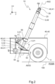
- the landing gear 10 In the retracted position POSR of the wheel 4, the landing gear 10 is positioned partially or totally in a housing 42 of the aircraft 40. On the Figure 2 , the landing gear 10 is shown in an embodiment where it is partially retracted into the housing 42.
- the wheel 4 is in the retracted position POSR during a flight of the aircraft 40 in order in particular to reduce the aerodynamic drag generated by the landing gear 10 during the advancement of the aircraft 40 in flight.
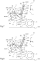
- the wheel 4 of the landing gear 10 can be positioned completely outside the housing 42 as shown in the Figure 1 , the wheel 4 being in contact with the ground 100.
- the wheel 4 is in the deployed position POSD, when the aircraft 40 is on the ground as well as before a landing phase and after a takeoff.
- the lander 10 rests on a horizontal ground 100.
- the landing gear 10 thus allows on the one hand the rolling of the aircraft 40 on the ground 100 and on the other hand the cushioning of a landing of the aircraft 40 on the ground 100, in particular thanks to the shock absorber 2 and the particular kinematics of the landing gear 10 according to the invention.
- the landing gear 10 thus comprises a particular architecture comprising two complementary bracings which together contribute to effectively maintaining the wheel 4 in the deployed position POSD when the landing gear 10 is subjected to various stresses such as vibrations, shocks, accelerations and ground forces, while remaining within predefined limits.
- the landing gear 10 in fact comprises, in the deployed position POSD, a main bracing of the balance 1 formed by the shock absorber 2, the connecting rod 6 and the third mechanical connection 53 and a secondary bracing of the shock absorber 2 formed by the brace 3, and therefore the first connecting rod 31, the second connecting rod 32 and the first mechanical connection 51.
- the installation of the elastic return member 71 associated with the architecture of the landing gear 10 also makes it possible to ensure locking of the strut 3, and therefore of the secondary bracing to resist these different stresses.
- the misalignment of the connecting rod 6 relative to the shock absorber 2 ensures traction of the strut 3, thus guaranteeing effective locking of the deployed position POSD of the wheel 4.
- This implementation of the elastic return member 71 associated with the architecture of the landing gear 10 also makes it possible to minimize the maneuvering forces that the actuator 5 must apply to move the wheel 4 between the deployed POSD and retracted POSR positions. This thus allows the use of an electric motor as actuator 5, or even a small cylinder, for example electric or pneumatic.
- the actuator 5 can be deactivated, i.e. can be controlled so as not to provide any force or torque on the second link 32.
- the locking of the strut 3 advantageously makes it possible, thanks to the use of the main and secondary bracing, to effectively maintain the wheel 4 in the deployed position, without the actuator 5 providing any force or torque.
- first link 31 and the second link 32 may have different lengths.
- a first length of the first link 31 may be greater than a second length of the second link 32 in accordance with the example shown in the figures.
- the axis of rotation AX32 of the second connecting rod 32 relative to the structure 41 is coincident with the axis of rotation AX5 of the electric motor constituting the actuator 5 and these axes of rotation AX31, AX56 form a plane perpendicular to the direction Z.
- the rotation axis AX56 of the sixth mechanical connection 56 and the rotation axis AX32 of the second connecting rod 32 relative to the structure 41 can form a plane perpendicular to a movement axis AX2 of the shock absorber 2 in the deployed position POSD.
- these axes of rotation AX56, AX32 of the first connecting rod 31 relative to the shock absorber 2 and of the second connecting rod 32 relative to the structure 41 may also be substantially coplanar with the axis of rotation AX51 of the first mechanical connection 51 in the deployed position POSD. In this way, when the first connecting rod 31 and the second connecting rod 32 are straight, they are aligned.
- the architecture of the landing gear 10 can be defined so that the axis of rotation of the connecting rod 6 relative to the balance 1, namely the axis of rotation AX53 of the third mechanical connection 53, is aligned with the axis of travel AX2 of the shock absorber 2 when the shock absorber 2 is compressed under the effect of a force substantially equal to a predetermined force and the wheel 4 is in the deployed position POSD.
- the axis of travel AX2 of the shock absorber 2 can be a translation axis of the rod 21 relative to the body 22. In this configuration, when the connecting rod 6 is straight, the connecting rod 6 is aligned with this axis of movement of the shock absorber 2.
- the shock absorber 2 is thus compressed when a significant force, directed partly vertically and upwards, is applied to the wheel 4. Such a significant force can be applied to the wheel 4 during a hard landing of the aircraft 40 in particular.
- the shock absorber 2 may also comprise a deformable end-of-travel stop 23 arranged in the body 22.
- This end-of-travel stop 23 is positioned in the body 22 and configured to deform when the shock absorber 2 compresses under the effect of a force greater than the predetermined force.
- the end-of-travel stop 23 may for example comprise a tube 25 as shown in the Figure 4 , the tube 25 being defined and dimensioned to deform, for example by buckling, from a force greater than the predetermined force exerted on the shock absorber 2.
- the end-of-travel stop 23 can deform directly under a force applied by the rod 21 to the end-of-travel stop 23, the rod 21 then bearing against the end-of-travel stop 23 as shown in the Figure 7 .
- the end-of-travel stop 23 can alternatively deform under a force applied by a fluid present in the body 22 and compressed by the rod 21, the rod 21 then not being in contact with the end-of-travel stop 23.
- the lander 10 may also include a lever 61, as shown in the figures 5 to 8 .
- the lever 61 is for example integral with the connecting rod 6 and configured to be very close, or even in contact with the first connecting rod 31 when the shock absorber 2 is compressed under the effect of a force substantially equal to the predetermined force.
- Other layouts of the lever 61 are possible depending on the kinematics of the landing gear 10.
- the lever 61 can for example example be integral with the rod 21, the rod 21 protruding sufficiently from the body 22 when the shock absorber 2 is fully compressed.
- the wheel 4 is in contact with the ground 100.
- a reaction of the ground is applied to the wheel 4 so that a force less than the predetermined force is exerted on the shock absorber 2.
- the shock absorber 2 is in an intermediate position in which the rod 21 is not bearing against the end-of-travel stop 23.
- the strut 3 is locked thanks to the tensile force of the elastic return member 71 and the stop device 72.
- the wheel 4 is held in the deployed position POSD.
Landscapes
- Engineering & Computer Science (AREA)
- Mechanical Engineering (AREA)
- Aviation & Aerospace Engineering (AREA)
- Transmission Devices (AREA)
- Vibration Dampers (AREA)
Claims (16)
- Einziehbares Landegestell (10) für ein Luftfahrzeug (40), wobei das Landegestell (10) umfasst:- einen Schwenkarm (1), der zur Anlenkung an eine Struktur (41) des Flugzeugs (40) vorgesehen ist und mindestens ein Rad (4) trägt, wobei das mindestens eine Rad (4) zwischen einer ausgefahrenen Position (POSD) und einer eingefahrenen Position (POSR) beweglich ist,- einen Stoßdämpfer (2) mit einer in einem Körper (22) verschiebbaren Stange (21), wobei der Stoßdämpfer (2) zur Anlenkung an die Struktur (41) vorgesehen ist,- einen Aktuator (5) und- eine Koppelstange (6), die einerseits über eine zweite mechanische Verbindung (52) mit einem einzigen Freiheitsgrad in der Drehung an dem Stoßdämpfer (2) und andererseits an dem Schwenkarm (1) angelenkt ist, wobei die Koppelstange (6) gegenüber dem Stoßdämpfer (2) versetzt ist, wenn eine Kraft unterhalb einer vorgegebenen Kraft auf den Stoßdämpfer (2) ausgeübt wird,dadurch gekennzeichnet, dass der Landegestell (10) umfasst:- eine Strebe (3) mit einem ersten Lenker (31) und einem zweiten Lenker (32), die über eine erste mechanische Verbindung (51) miteinander gelenkig verbunden sind, wobei der erste Lenker (31) an dem Stoßdämpfer (2) angelenkt ist, wobei der Aktuator (5) einerseits zur Verbindung mit der Struktur (41) und andererseits mit dem zweiten Lenker (32) vorgesehen ist, um den zweiten Lenker (32) relativ zur Struktur (41) in Drehung zu versetzen, und- eine Verriegelungsvorrichtung (7) mit einem elastischen Rückstellelement (71) und einer Anschlagvorrichtung (72), wobei das elastische Rückstellelement (71) mit zwei Enden jeweils an der Strebe (3) und an einer Gelenkanordnung befestigt ist, die den Schwenkarm (1), die Koppelstange (6) und eine dritte mechanische Verbindung (53) zwischen dem Schwenkarm (1) und der Koppelstange (6) umfasst, wobei das elastische Rückstellelement (71) eine Zugkraft zwischen der Strebe (3) und der Gelenkanordnung ausübt, wobei die Anschlagvorrichtung (72) konfiguriert ist, um eine durch die Zugkraft hervorgerufene Relativbewegung zwischen dem ersten und dem zweiten Lenker (31, 32) um eine Drehachse (AX51) der ersten mechanischen Verbindung (51) zu stoppen, wenn sich das Rad (4) in der ausgefahrenen Position (POSD) befindet.
- Landegestell (10) nach Anspruch 1,
bei dem der Aktuator (5) ein rotierender Elektromotor ist. - Landegestell (10) nach einem der Ansprüche 1 bis 2,
bei dem die Koppelstange (6) an der Stange (21) angelenkt ist, der erste Lenker (31) an dem Körper (22) angelenkt ist, und der Körper (22) an der Struktur (41) angelenkt ist. - Landegestell (10) nach einem der Ansprüche 1 bis 2,
bei dem die Koppelstange (6) an dem Körper (22) angelenkt ist, der erste Lenker (31) an der Stange (21) angelenkt ist, und die Stange (21) an der Struktur (41) angelenkt ist. - Landegestell (10) nach einem der Ansprüche 1 bis 4,
bei dem eine Drehachse des ersten Lenkers (31) relativ zu dem Stoßdämpfer (2) und eine Drehachse des zweiten Lenkers (32) relativ zu der Struktur (41) eine zu einer Schwenkachse (AX2) des Stoßdämpfers (2) senkrechte Ebene bilden, wenn sich das Rad (4) in der ausgefahrenen Position (POSD) befindet. - Landegestell (10) nach einem der Ansprüche 1 bis 5,
bei dem eine Drehachse des ersten Lenkers (31) relativ zu dem Stoßdämpfer (2) und eine Drehachse des zweiten Lenkers (32) relativ zu der Struktur (41) und eine Drehachse des ersten Lenkers (31) relativ zu dem zweiten Lenker (32) parallel zueinander und koplanar sein können, wenn sich das Rad (4) in der ausgefahrenen Position (POSD) befindet. - Landegestell (10) nach einem der Ansprüche 1 bis 6,
bei dem das elastische Rückstellelement (71) mit einem seiner beiden Enden an dem ersten Lenker (31), an dem zweiten Lenker (32) oder an der ersten mechanischen Verbindung (51) befestigt ist, und mit dem anderen seiner beiden Enden an dem Schwenkarm (1), an der Koppelstange (6) oder an dem Gelenk zwischen dem Schwenkarm (1) und der Koppelstange (6) befestigt ist. - Landegestell (10) nach einem der Ansprüche 1 bis 7,
bei dem die Koppelstange (6) gerade ist und mit dem Stoßdämpfer (2) fluchtet, wenn der Stoßdämpfer (2) unter einer der vorgegebenen Kraft entsprechenden Kraft zusammengedrückt wird, wenn sich das Rad (4) in der ausgefahrenen Position (POSD) befindet. - Landegestell (10) nach einem der Ansprüche 1 bis 8,
bei dem der Stoßdämpfer (2) einen verformbaren Endanschlag (23) aufweist, der in dem Körper (22) angeordnet ist, wobei der Endanschlag (23) konfiguriert ist, um sich zu verformen, wenn das Landegestell (10) unter einer Kraft zusammengedrückt wird, die größer ist als die vorgegebene Kraft, wenn sich das Rad (4) in der ausgefahrenen Position (POSD) befindet. - Landegestell (10) nach einem der Ansprüche 1 bis 9,
bei dem das Landegestell (10) einen Hebel (61) aufweist, und der Hebel (61) konfiguriert ist, um mit dem ersten Lenker (31) in Kontakt zu kommen, wenn der Stoßdämpfer (2) unter einer Kraft zusammengedrückt wird, die gleich der vorgegebenen Kraft ist, wenn sich das Rad (4) in der ausgefahrenen Position (POSD) befindet, und der Hebel (61) eingerichtet ist, um eine Verschiebung des ersten Lenkers (31) zu bewirken, wenn der Stoßdämpfer (2) unter einer Kraft zusammengedrückt wird, die größer ist als die vorgegebene Kraft. - Landegestell (10) nach den Ansprüchen 9 und 10,
bei dem der Hebel (61) konfiguriert ist, um mit dem ersten Lenker (31) in Kontakt zu stehen, wenn die Stange (22) gegen den Endanschlag (23) drückt. - Landegestell (10) nach einem der Ansprüche 10 bis 11,
bei dem der Hebel (61) an der Koppelstange (6) oder an der Stange (21) angeordnet ist, wenn die Koppelstange (6) an der Stange (21) angelenkt ist, oder an dem Körper (22) angeordnet ist, wenn die Koppelstange (6) an dem Körper (22) angelenkt ist. - Landegestell (10) nach einem der Ansprüche 9 bis 12,
bei dem der Dämpfer (2) ein Ventil (24) aufweist, das konfiguriert ist, um einen Innenraum (INT) in dem Körper (22) mit einer Außenumgebung (EXT) außerhalb des Körpers (22) zu verbinden, wobei das Ventil (24) sich öffnet, wenn ein Druck in dem Körper (22) größer als ein vorgegebener Druck ist. - Landegestell (10) nach einem der Ansprüche 1 bis 13,
bei dem eine erste Länge des ersten Lenkers (31) größer ist als eine zweite Länge des zweiten Lenkers (32). - Landegestell (10) nach Anspruch 14,
bei dem die zweite Länge zwischen einem Viertel und einem Fünftel der ersten Länge beträgt. - Luftfahrzeug (40) mit mindestens einem Landegestell (10) nach einem der Ansprüche 1 bis 15.
Applications Claiming Priority (1)
| Application Number | Priority Date | Filing Date | Title |
|---|---|---|---|
| FR2212992A FR3143003A1 (fr) | 2022-12-08 | 2022-12-08 | Atterrisseur à balancier rétractable muni d’un moteur électrique et aéronef muni d’au moins un tel atterrisseur |
Publications (2)
| Publication Number | Publication Date |
|---|---|
| EP4382417A1 EP4382417A1 (de) | 2024-06-12 |
| EP4382417B1 true EP4382417B1 (de) | 2025-06-25 |
Family
ID=85685790
Family Applications (1)
| Application Number | Title | Priority Date | Filing Date |
|---|---|---|---|
| EP23199996.2A Active EP4382417B1 (de) | 2022-12-08 | 2023-09-27 | Einziehfahrwerk mit einer geschleppten lenkerachse und einem elektromotor, und ein luftfahrzeug mit mindestens einem solchen fahrwerk |
Country Status (3)
| Country | Link |
|---|---|
| US (1) | US12227287B2 (de) |
| EP (1) | EP4382417B1 (de) |
| FR (1) | FR3143003A1 (de) |
Family Cites Families (11)
| Publication number | Priority date | Publication date | Assignee | Title |
|---|---|---|---|---|
| FR2884801B1 (fr) | 2005-04-22 | 2008-11-14 | Eurocopter France | Atterrisseur auxillaire de nez, structure porteuse et aeronef a voilure tournante |
| US7942366B2 (en) | 2005-06-23 | 2011-05-17 | Karem Aircraft, Inc. | Aircraft landing gear with integrated extension, retraction, and leveling feature |
| FR2946319B1 (fr) * | 2009-06-05 | 2012-11-30 | Messier Dowty Sa | Procede de manoeuvre d'un atterrisseur a contrefiche briseuse |
| FR3001708B1 (fr) * | 2013-02-06 | 2015-02-13 | Eurocopter France | Train d'atterrissage retractable, aeronef muni dudit train d'atterrissage, et procede de manoeuvre dudit train d'atterrissage |
| FR3011816B1 (fr) | 2013-10-15 | 2016-12-09 | Eurocopter France | Train d'atterrissage a balancier et giravion |
| ITUA20162712A1 (it) | 2016-04-19 | 2017-10-19 | Magnaghi Aeronautica S P A | Struttura di Sistema Carrello per Aeromobili provvisto di attuazione elettromeccanica e Aeromobile provvista di tale Struttura |
| EP3248869B1 (de) | 2016-05-25 | 2018-09-12 | AIRBUS HELICOPTERS DEUTSCHLAND GmbH | Einziehen/ausfahren eines fahrwerkes in einem flugzeug |
| FR3073494B1 (fr) * | 2017-11-15 | 2019-12-13 | Safran Landing Systems | Procede de manoeuvre d'un atterrisseur d'aeronef entre une position retractee et une position deployee |
| US11142304B2 (en) * | 2017-11-29 | 2021-10-12 | Sikorsky Aircraft Corporation | Retractable landing gear system for a vertical takeoff and landing (VTOL) aircraft |
| FR3074777B1 (fr) * | 2017-12-11 | 2024-01-05 | Safran Landing Systems | Procede de manœuvre d'un atterrisseur d'aeronef entre une position deployee et une position retractee |
| US11407500B2 (en) * | 2020-09-15 | 2022-08-09 | Safran Landing Systems Canada, Inc. | Landing gear with shortening motion |
-
2022
- 2022-12-08 FR FR2212992A patent/FR3143003A1/fr active Pending
-
2023
- 2023-09-27 EP EP23199996.2A patent/EP4382417B1/de active Active
- 2023-10-16 US US18/380,237 patent/US12227287B2/en active Active
Also Published As
| Publication number | Publication date |
|---|---|
| EP4382417A1 (de) | 2024-06-12 |
| FR3143003A1 (fr) | 2024-06-14 |
| US12227287B2 (en) | 2025-02-18 |
| US20240190559A1 (en) | 2024-06-13 |
Similar Documents
| Publication | Publication Date | Title |
|---|---|---|
| EP3495263B1 (de) | Verfahren zum manövrieren eines luftfahrzeugfahrwerks zwischen einer eingezogenen und einer ausgefahrenen position | |
| EP2454152B1 (de) | Bugfahrwek mit stellvorrichtung, welche sowohl das einfahren des fahrweks als auch dessen lenkung bewerkstelligt | |
| CA2892475C (fr) | Atterrisseur a contrefiche secondaire a realignement | |
| CA2744503A1 (fr) | Dispositif de raccourcissement d'un atterrisseur d'aeronef | |
| FR3056552A1 (fr) | Harpon d'ancrage externe pour aeronef | |
| EP4164947B1 (de) | Fahrwerk eines luftfahrzeugs, das mit mindestens einem motorisierten rad ausgestattet ist | |
| EP3006333B1 (de) | Fahrwerk eines luftfahrzeugs | |
| EP2436598A2 (de) | Fahrwerk, mit diesem Fahrwerk ausgestattetes Flugzeug und Landeverfahren dieses Flugzeugs | |
| CA3195417A1 (fr) | Atterrisseur d'aeronef equipe d'un dispositif de verrouillage a ressort a lame | |
| EP3539867A1 (de) | Manövrierverfahren für ein fahrwerk zwischen ausgefahrene und eingefahrene position | |
| EP2753543A1 (de) | Vorrichtung zur kopplung eines aktuators zur steuerung des fahrwerks eines flugzeugs | |
| EP0072720A1 (de) | Fahrwerk für Flugzeug | |
| EP4382417A1 (de) | Einziehfahrwerk mit einer geschleppten lenkerachse und einem elektromotor, und ein luftfahrzeug mit mindestens einem solchen fahrwerk | |
| FR3001708A1 (fr) | Train d'atterrissage retractable, aeronef muni dudit train d'atterrissage, et procede de manoeuvre dudit train d'atterrissage | |
| CA3036788C (fr) | Procede de manoeuvre d'un atterrisseur d'aeronef entre une position deployee et une position retractee | |
| CA3048083C (fr) | Mecanisme de verrouillage d'actionneur de roue | |
| EP4153480B1 (de) | Einziehfahrwerk mit einer knickstrebe und darin integriertem aktuator | |
| EP4347392B1 (de) | Fahrwerk eines flugzeugs mit mindestens einem angetriebenen rad | |
| EP4126664B1 (de) | Flugzeugfahrwerk mit einer feder, die der rotation zwischen den oberen und unteren elementen des fahrwerkes entgegengerichtet ist | |
| FR3144107A1 (fr) | Atterrisseur à mécanisme de manœuvre simplifié. | |
| WO2025247923A1 (fr) | Atterrisseur a mouvement combine de retraction et aeronef ainsi equipe | |
| WO2023156511A1 (fr) | Atterrisseur a longueur variable et aéronef équipé d'un tel atterrisseur | |
| FR2524860A1 (fr) | Train d'atterrissage pour aeronef tel que par exemple les helicopteres | |
| FR2510511A1 (fr) | Train d'atterrissage |
Legal Events
| Date | Code | Title | Description |
|---|---|---|---|
| PUAI | Public reference made under article 153(3) epc to a published international application that has entered the european phase |
Free format text: ORIGINAL CODE: 0009012 |
|
| STAA | Information on the status of an ep patent application or granted ep patent |
Free format text: STATUS: THE APPLICATION HAS BEEN PUBLISHED |
|
| AK | Designated contracting states |
Kind code of ref document: A1 Designated state(s): AL AT BE BG CH CY CZ DE DK EE ES FI FR GB GR HR HU IE IS IT LI LT LU LV MC ME MK MT NL NO PL PT RO RS SE SI SK SM TR |
|
| STAA | Information on the status of an ep patent application or granted ep patent |
Free format text: STATUS: REQUEST FOR EXAMINATION WAS MADE |
|
| 17P | Request for examination filed |
Effective date: 20240614 |
|
| P01 | Opt-out of the competence of the unified patent court (upc) registered |
Free format text: CASE NUMBER: APP_35863/2024 Effective date: 20240614 |
|
| RBV | Designated contracting states (corrected) |
Designated state(s): AL AT BE BG CH CY CZ DE DK EE ES FI FR GB GR HR HU IE IS IT LI LT LU LV MC ME MK MT NL NO PL PT RO RS SE SI SK SM TR |
|
| GRAP | Despatch of communication of intention to grant a patent |
Free format text: ORIGINAL CODE: EPIDOSNIGR1 |
|
| STAA | Information on the status of an ep patent application or granted ep patent |
Free format text: STATUS: GRANT OF PATENT IS INTENDED |
|
| INTG | Intention to grant announced |
Effective date: 20250321 |
|
| GRAS | Grant fee paid |
Free format text: ORIGINAL CODE: EPIDOSNIGR3 |
|
| GRAA | (expected) grant |
Free format text: ORIGINAL CODE: 0009210 |
|
| STAA | Information on the status of an ep patent application or granted ep patent |
Free format text: STATUS: THE PATENT HAS BEEN GRANTED |
|
| AK | Designated contracting states |
Kind code of ref document: B1 Designated state(s): AL AT BE BG CH CY CZ DE DK EE ES FI FR GB GR HR HU IE IS IT LI LT LU LV MC ME MK MT NL NO PL PT RO RS SE SI SK SM TR |
|
| REG | Reference to a national code |
Ref country code: GB Ref legal event code: FG4D Free format text: NOT ENGLISH |
|
| REG | Reference to a national code |
Ref country code: CH Ref legal event code: EP |
|
| REG | Reference to a national code |
Ref country code: DE Ref legal event code: R096 Ref document number: 602023004281 Country of ref document: DE |
|
| REG | Reference to a national code |
Ref country code: CH Ref legal event code: EP |
|
| REG | Reference to a national code |
Ref country code: IE Ref legal event code: FG4D Free format text: LANGUAGE OF EP DOCUMENT: FRENCH |
|
| PG25 | Lapsed in a contracting state [announced via postgrant information from national office to epo] |
Ref country code: FI Free format text: LAPSE BECAUSE OF FAILURE TO SUBMIT A TRANSLATION OF THE DESCRIPTION OR TO PAY THE FEE WITHIN THE PRESCRIBED TIME-LIMIT Effective date: 20250625 |
|
| REG | Reference to a national code |
Ref country code: LT Ref legal event code: MG9D |
|
| PG25 | Lapsed in a contracting state [announced via postgrant information from national office to epo] |
Ref country code: NO Free format text: LAPSE BECAUSE OF FAILURE TO SUBMIT A TRANSLATION OF THE DESCRIPTION OR TO PAY THE FEE WITHIN THE PRESCRIBED TIME-LIMIT Effective date: 20250925 Ref country code: GR Free format text: LAPSE BECAUSE OF FAILURE TO SUBMIT A TRANSLATION OF THE DESCRIPTION OR TO PAY THE FEE WITHIN THE PRESCRIBED TIME-LIMIT Effective date: 20250926 |
|
| PG25 | Lapsed in a contracting state [announced via postgrant information from national office to epo] |
Ref country code: BG Free format text: LAPSE BECAUSE OF FAILURE TO SUBMIT A TRANSLATION OF THE DESCRIPTION OR TO PAY THE FEE WITHIN THE PRESCRIBED TIME-LIMIT Effective date: 20250625 |
|
| PG25 | Lapsed in a contracting state [announced via postgrant information from national office to epo] |
Ref country code: HR Free format text: LAPSE BECAUSE OF FAILURE TO SUBMIT A TRANSLATION OF THE DESCRIPTION OR TO PAY THE FEE WITHIN THE PRESCRIBED TIME-LIMIT Effective date: 20250625 |
|
| PGFP | Annual fee paid to national office [announced via postgrant information from national office to epo] |
Ref country code: FR Payment date: 20250922 Year of fee payment: 3 Ref country code: AT Payment date: 20251020 Year of fee payment: 3 |
|
| PG25 | Lapsed in a contracting state [announced via postgrant information from national office to epo] |
Ref country code: RS Free format text: LAPSE BECAUSE OF FAILURE TO SUBMIT A TRANSLATION OF THE DESCRIPTION OR TO PAY THE FEE WITHIN THE PRESCRIBED TIME-LIMIT Effective date: 20250925 |
|
| PG25 | Lapsed in a contracting state [announced via postgrant information from national office to epo] |
Ref country code: LV Free format text: LAPSE BECAUSE OF FAILURE TO SUBMIT A TRANSLATION OF THE DESCRIPTION OR TO PAY THE FEE WITHIN THE PRESCRIBED TIME-LIMIT Effective date: 20250625 |
|
| REG | Reference to a national code |
Ref country code: NL Ref legal event code: MP Effective date: 20250625 |
|
| PG25 | Lapsed in a contracting state [announced via postgrant information from national office to epo] |
Ref country code: NL Free format text: LAPSE BECAUSE OF FAILURE TO SUBMIT A TRANSLATION OF THE DESCRIPTION OR TO PAY THE FEE WITHIN THE PRESCRIBED TIME-LIMIT Effective date: 20250625 |
|
| PG25 | Lapsed in a contracting state [announced via postgrant information from national office to epo] |
Ref country code: PT Free format text: LAPSE BECAUSE OF FAILURE TO SUBMIT A TRANSLATION OF THE DESCRIPTION OR TO PAY THE FEE WITHIN THE PRESCRIBED TIME-LIMIT Effective date: 20251027 |
|
| REG | Reference to a national code |
Ref country code: AT Ref legal event code: MK05 Ref document number: 1806238 Country of ref document: AT Kind code of ref document: T Effective date: 20250625 |
|
| PG25 | Lapsed in a contracting state [announced via postgrant information from national office to epo] |
Ref country code: IS Free format text: LAPSE BECAUSE OF FAILURE TO SUBMIT A TRANSLATION OF THE DESCRIPTION OR TO PAY THE FEE WITHIN THE PRESCRIBED TIME-LIMIT Effective date: 20251025 |
|
| PG25 | Lapsed in a contracting state [announced via postgrant information from national office to epo] |
Ref country code: AT Free format text: LAPSE BECAUSE OF FAILURE TO SUBMIT A TRANSLATION OF THE DESCRIPTION OR TO PAY THE FEE WITHIN THE PRESCRIBED TIME-LIMIT Effective date: 20250625 Ref country code: SM Free format text: LAPSE BECAUSE OF FAILURE TO SUBMIT A TRANSLATION OF THE DESCRIPTION OR TO PAY THE FEE WITHIN THE PRESCRIBED TIME-LIMIT Effective date: 20250625 |
|
| PGFP | Annual fee paid to national office [announced via postgrant information from national office to epo] |
Ref country code: IT Payment date: 20250930 Year of fee payment: 3 |
|
| PG25 | Lapsed in a contracting state [announced via postgrant information from national office to epo] |
Ref country code: CZ Free format text: LAPSE BECAUSE OF FAILURE TO SUBMIT A TRANSLATION OF THE DESCRIPTION OR TO PAY THE FEE WITHIN THE PRESCRIBED TIME-LIMIT Effective date: 20250625 |
|
| PG25 | Lapsed in a contracting state [announced via postgrant information from national office to epo] |
Ref country code: PL Free format text: LAPSE BECAUSE OF FAILURE TO SUBMIT A TRANSLATION OF THE DESCRIPTION OR TO PAY THE FEE WITHIN THE PRESCRIBED TIME-LIMIT Effective date: 20250625 |
|
| PG25 | Lapsed in a contracting state [announced via postgrant information from national office to epo] |
Ref country code: EE Free format text: LAPSE BECAUSE OF FAILURE TO SUBMIT A TRANSLATION OF THE DESCRIPTION OR TO PAY THE FEE WITHIN THE PRESCRIBED TIME-LIMIT Effective date: 20250625 |
|
| PG25 | Lapsed in a contracting state [announced via postgrant information from national office to epo] |
Ref country code: SK Free format text: LAPSE BECAUSE OF FAILURE TO SUBMIT A TRANSLATION OF THE DESCRIPTION OR TO PAY THE FEE WITHIN THE PRESCRIBED TIME-LIMIT Effective date: 20250625 |
|
| PG25 | Lapsed in a contracting state [announced via postgrant information from national office to epo] |
Ref country code: ES Free format text: LAPSE BECAUSE OF FAILURE TO SUBMIT A TRANSLATION OF THE DESCRIPTION OR TO PAY THE FEE WITHIN THE PRESCRIBED TIME-LIMIT Effective date: 20250625 |
|
| PG25 | Lapsed in a contracting state [announced via postgrant information from national office to epo] |
Ref country code: RO Free format text: LAPSE BECAUSE OF FAILURE TO SUBMIT A TRANSLATION OF THE DESCRIPTION OR TO PAY THE FEE WITHIN THE PRESCRIBED TIME-LIMIT Effective date: 20250625 |
|
| PG25 | Lapsed in a contracting state [announced via postgrant information from national office to epo] |
Ref country code: DK Free format text: LAPSE BECAUSE OF FAILURE TO SUBMIT A TRANSLATION OF THE DESCRIPTION OR TO PAY THE FEE WITHIN THE PRESCRIBED TIME-LIMIT Effective date: 20250625 |
|
| PLBE | No opposition filed within time limit |
Free format text: ORIGINAL CODE: 0009261 |
|
| STAA | Information on the status of an ep patent application or granted ep patent |
Free format text: STATUS: NO OPPOSITION FILED WITHIN TIME LIMIT |
|
| REG | Reference to a national code |
Ref country code: CH Ref legal event code: L10 Free format text: ST27 STATUS EVENT CODE: U-0-0-L10-L00 (AS PROVIDED BY THE NATIONAL OFFICE) Effective date: 20260507 |