EP4382408A1 - Method of manufacturing a wall made of metal plates welded together and corresponding wall - Google Patents
Method of manufacturing a wall made of metal plates welded together and corresponding wall Download PDFInfo
- Publication number
- EP4382408A1 EP4382408A1 EP22306836.2A EP22306836A EP4382408A1 EP 4382408 A1 EP4382408 A1 EP 4382408A1 EP 22306836 A EP22306836 A EP 22306836A EP 4382408 A1 EP4382408 A1 EP 4382408A1
- Authority
- EP
- European Patent Office
- Prior art keywords
- edge
- stiffened plate
- plate
- wall
- stiffened
- Prior art date
- Legal status (The legal status is an assumption and is not a legal conclusion. Google has not performed a legal analysis and makes no representation as to the accuracy of the status listed.)
- Withdrawn
Links
Images




Classifications
-
- B—PERFORMING OPERATIONS; TRANSPORTING
- B63—SHIPS OR OTHER WATERBORNE VESSELS; RELATED EQUIPMENT
- B63B—SHIPS OR OTHER WATERBORNE VESSELS; EQUIPMENT FOR SHIPPING
- B63B73/00—Building or assembling vessels or marine structures, e.g. hulls or offshore platforms
- B63B73/40—Building or assembling vessels or marine structures, e.g. hulls or offshore platforms characterised by joining methods
- B63B73/43—Welding, e.g. laser welding
-
- B—PERFORMING OPERATIONS; TRANSPORTING
- B63—SHIPS OR OTHER WATERBORNE VESSELS; RELATED EQUIPMENT
- B63B—SHIPS OR OTHER WATERBORNE VESSELS; EQUIPMENT FOR SHIPPING
- B63B3/00—Hulls characterised by their structure or component parts
- B63B3/14—Hull parts
- B63B3/68—Panellings; Linings, e.g. for insulating purposes
-
- B—PERFORMING OPERATIONS; TRANSPORTING
- B63—SHIPS OR OTHER WATERBORNE VESSELS; RELATED EQUIPMENT
- B63B—SHIPS OR OTHER WATERBORNE VESSELS; EQUIPMENT FOR SHIPPING
- B63B73/00—Building or assembling vessels or marine structures, e.g. hulls or offshore platforms
- B63B73/20—Building or assembling prefabricated vessel modules or parts other than hull blocks, e.g. engine rooms, rudders, propellers, superstructures, berths, holds or tanks
-
- B—PERFORMING OPERATIONS; TRANSPORTING
- B63—SHIPS OR OTHER WATERBORNE VESSELS; RELATED EQUIPMENT
- B63B—SHIPS OR OTHER WATERBORNE VESSELS; EQUIPMENT FOR SHIPPING
- B63B2231/00—Material used for some parts or elements, or for particular purposes
- B63B2231/02—Metallic materials
Definitions
- the present invention relates to the field of metallic constructions, and in particular to the construction of a wall made of a metal plates welded together.
- Metallic floating marine structures such as vessels, platforms, buoys, and floaters may comprise hulls having walls made of metal plates welded together and provided with stiffeners welded to the plates.
- the stiffeners are for example provided as metallic stiffening profiles, which are welded onto the plates to be stiffened.
- Each stiffening profile has for example a cross-section having a L shape, a T shape, a U shape or H shape.
- stiffeners allow limiting the thickness of the plates, while preserving the floatability of the structure. Thinner plates result in faster welding and easier shaping, albeit it increases welding works since stiffeners have to be welded onto the plates.
- Welding is traditionally on the critical path for metal constructions since it is usually a lengthy procedure, which requires highly skilled artisans, while risks of defects are significant and may result in final work rebuttal.
- One of the aims of the invention is to propose a method of manufacturing a wall made of metal plates welded together which allows a reduction of the weight whilst being easy and cost-effective.
- the invention proposes method of manufacturing a wall made of metal plates welded together along edges of the plates, the method comprising the steps of:
- the wall is manufactured by welding plates including stiffened plates, each stiffened plate being provided with a stiffener formed by a rim provided along an edge of the stiffened plate.
- Each stiffened plate forms a fraction of the wall and the rim provided on each stiffened plate forms a stiffener.
- a stiffened wall can thus be obtained while limiting the welding operations, as the rim of each stiffened plate is formed integrally in a single piece of material with the stiffened plate and does not need to be welded to the stiffened plate.
- Each stiffened plate provided with a rim integrally formed in a single piece of material with the stiffened plate is obtained easily, for example by forming a blank, in particular by folding a blank to define the stiffened plate and the rim provided along a first edge of the stiffened plate.
- the manufacturing method comprising one or several of the following optional features, taken individually or in any technically feasible combination:
- the invention also relates to a method of manufacturing a marine structure comprising a wall, in particular a vessel, a platform, a buoy or a floater, wherein the wall is manufactured according to the manufacturing method as defined above.
- the invention further relates to a wall of a metal construction, in particular a marine structure, the wall being made of metal plates welded together along edges of the plates, the plates including at least one stiffened plate, each stiffened plate being provided with a rim along a first edge of the stiffened plate opposite a second edge of the stiffened plate, the rim being made in a single piece of metal with the stiffened plate, the first edge of the stiffened plate being welded to an edge of another plate such that the rim of the stiffened plate protrudes on one of the two opposed sides of the wall at the junction between the stiffened plate and said other plate.
- the wall comprises one or several of the following optional features, taken individually or according to any technically feasible combination:
- the invention further relates to a marine structure, e.g. a vessel, a platform, a buoy or a floater, in particular a floater of a floating structure of an off-shore wind turbine, the marine structure including at least one wall as defined above.
- a marine structure e.g. a vessel, a platform, a buoy or a floater, in particular a floater of a floating structure of an off-shore wind turbine, the marine structure including at least one wall as defined above.
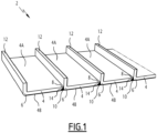
- the wall 2 illustrated on Figure 1 is formed of a plurality of metal plates 4 arranged edge-to-edge and welded together along their adjacent edges welded.
- Each plate 4 forms a fraction of the wall 2.
- Each plate 4 comprises a first edge 6 and second edge 8 opposite to the first edge 6.
- the first edge 6 and the second edge 8 are preferably parallel.
- Each plate 4 has a first side 4A and a second side 4B opposite the first side 4A.
- Each plate 4 has its first edge 6 welded to the second edge 8 of an adjacent plate 4 and/or its second edge 8 welded to the first edge 6 of another adjacent plate 4.
- Welding beads 10 extend along the edges of the plates 4 welded together.
- the plates 4 include at least one stiffened plate 4.
- the plates 4 may all be stiffened plates 4 or may optionally comprise at least one non-stiffened plate 4.
- a plate 4 designates any plate 4 of the wall 2, i.e. a stiffened plate 4 or a non-stiffened plate 4.
- Each stiffened plate 4 is provided with a rim 12 formed integrally in one single piece of metal with the stiffened plate 4.
- the rim 12 extending along the first edge of the plate 4 acts as a stiffener for the stiffened plate 4.
- each stiffened plate 4 protrudes for example from the first side 4A of the stiffened plate 4.
- Each stiffened plate 4 has its first edge 6 welded to the second edge of another plate 4, such that the rim 12 of this stiffened plate 4 protrudes from the wall 6 along the junction between the stiffened plate 4 and the other plate 4.
- each stiffened plate 4 protruding from the wall 2 acts a stiffener for the wall 2 as a whole.
- the wall 2 is formed of a series of stiffened plates 4, the first edge 6 of each stiffened plate 4 being welded to the second edge 8 of the next stiffened plate 4 of the series of stiffened plates 4.
- the rims 12 of all the stiffened plates 4 protrude on a same side of the wall 2.
- this first edge 6 of the last stiffened plate of the series of stiffened plates 4 is free.
- the second edge 8 of each plate 4 welded to the first edge 6 of a stiffened plate 4 is provided with a chamfer 14.
- the chamfer 14 is configured to create a groove between the second edge 8 of the plate 4 and the first edge 6 of the stiffened plate 4 for welding the second edge 8 to the first edge 6 with filler material.
- the chamfer 14 is preferably inclined such as to be orientated opposite the first side 4A of the stiffened plate 4 to which the second edge is welded.
- each stiffened plat 4 is provided with a chamfer 14 orientated opposite the first side 4A of the stiffened plate 4.
- a plurality of flat plates 4 are for example welded to each other such as to be coplanar and to form a flat wall 2, the rim 12 of each stiffened plate 4 protruding from the flat wall 2.
- two flat plates 4 including at least one stiffened plate 4 provided with a rim 12 are welded together with a non-zero angle between the plates 4.
- this allows forming a wall 2 having facets separated by corners, each plate 4 defining a respective facet. Even more in particular, this allows forming a wall 2 extending along a polygonal contour, each plate 4 defining a respective facet of the wall 2.
- two or more flat stiffened plates 4 are welded together with a non-zero angle between the plates 4 of each pair of adjacent plates 4.
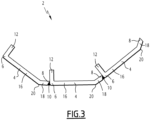
- At least one plate 4 in particular at least one stiffened plate 4, comprises a first flat portion 16 adjacent the first edge 6 and a second flat portion 18 adjacent the second edge 8, the first flat portion 16 and the second flat portion 18 defining a non-zero angle between them.
- the plate 4 comprises for example an intermediate fold 20 located between the first flat portion 16 and the second flat portion 18.
- the intermediate fold 20 is preferably parallel to the first edge 6 and the second edge 8 and located at a distance from the first edge 6 and at a distance from the second edge 8.
- first flat portion 16 extends from the intermediate fold 20 to the first edge 6 and/or the second flat portion 18 extends from the intermediate fold 20 to the second edge 8.
- a wall 2 is for example obtained with welding a plurality of plates 4, including at least one stiffened plate 4, each having a first flat portion 16 and a second flat portion 18, with welding the first edge 6 of a plate 4 to the second edge 6 of another plate 4 such that the first portion 6 of the plate 4 is coplanar with the second potion 18 of the other plate 4.
- Each facet is defined by a first potion 16 of one of the plates 4 and the second portion 18 of an adjacent plate 4.
- At least one or each plate 4, in particular at least one or each stiffened plate 4, is arched between the first edge 6 and the the second edge 8 along a curve, in particular a portion of a circle.
- At least one or each stiffened plate 4 is optionally provided with at least one additional stiffener 22 welded to the stiffened plate 4 and extending transversely between the first edge 6 and the second edge 8 of the stiffened plate 4.
- Each additional stiffener 22 extends for example on the first side 4A of the stiffened plate 4, from the rim 12 to the second edge 8.
- Each additional stiffener 22 is for example a metal profile.
- Each additional stiffener 22 has for example a cross-section exhibiting a L shape, a T shape, a U shape or a H shape.
- each stiffened plate 4 is for example profiled along the first edge 6 of the plate 4.
- each stiffened plate 4 has for example a cross-section that is straight.
- the rim 12 extends for example at an angle comprised between 60 and 120° with respect to the stiffened plate 4 or a flat portion of the stiffened plate 4 adjacent the first edge 6, e.g. a first flat portion 16 of the stiffened plate 4.
- each stiffened plate 4 has a cross-section that is straight and extends at an angle of 90° with respect to the stiffened plate 4 or the first flat portion 16 of the stiffened plate 4.
- the rim 12 of at least one or each stiffened plate 4 has for example a cross-section that is curved.
- At least one or each stiffened plate 4 is curved with a first radius of curvature between the first edge 6 and the second edge 8 and the rim 12 is curved with a second radius of curvature strictly greater than the first radius of curvature.
- the rim 12 of each stiffened plate 4 has a curvature strictly greater than that of the stiffened plate 4.
- the rim 12 of at least one or each stiffened plate 4 has for example a cross-section that has two opposite curvatures separated by a point of inflexion or a straight section.
- the rim 12 of at least one or each stiffened plate 4 has for example a cross-section that has two opposite curvatures separated by a point of inflexion.
- the shape of the cross-section of the rim 12 of each stiffened plate 4 allows tuning the stiffness imparted by the rim 12.
- a stiffened plate 4 that is curved may be provided with a rim 12 having a straight cross-section.
- the rims 12 of the stiffened plates 4 protrude on either sides of the wall 2.
- the rim 12 of at least one stiffened plate 4 protrudes on one side of the wall 2 and the rim 12 of at least one stiffened plate 4 protrudes on the other side of the wall 2.
- the stiffened plates 4 are arranged alternately such that the rim 12 of the preceding stiffened plate 4 protrudes on one side of the wall 2 and the rim of the following stiffened plate 4 protrudes on the other side of the wall 2.
- each one of the stiffened walls of Figures 1 - 6 is made of identical stiffened plates 4.
- a wall 2 incorporates at least two stiffened plates 4 which are of different shape and/or are provided with rims 12 of different shapes. This can be contemplated for tuning the overall weight and/or overall stiffness of the wall 2.
- a wall 2 incorporates for example at least one stiffened plate 4 which is flat between the first edge 6 and the second edge 8 (see e.g. Figure 1 ) and/or at least one stiffened plate 4 which is arched between the first edge 6 and the second edge 8 (see e.g. Figure 4 ), preferably along a portion of circle, and/or at least one stiffened plate 4 which has a first flat portion 16 adjacent the first edge 6 of the stiffened plate 4 and a second flat portion 18 adjacent the second edge 8, the first flat portion 16 and the second flat portion 18 extending at a non-zero angle one relative to the other (see e.g. Figure 3 ).
- a wall 2 incorporates for example at least one stiffened plate 4 provided with a rim 12 of straight profile and/or at least one stiffened plate 4 with a rim 12 of curved profile with a curvature on only one side and/or at least one stiffened plate 4 with a rim 12 of curved profile with two opposed curvatures.
- a wall 2 made of plate 4 welded together including at least one stiffened plate 4 may be incorporated in a metal construction, in particular in a marine structure, such as a vessel, a platform, a buoy or a floater.
- the structure 30 illustrated Figure 7 and 8 comprises a tubular body 32 extending along a central axis A and two end plates 34 closing the axial ends of the body 32, the body 32 comprising at least one section 36 each section 36 being formed of a stiffened wall 2 of circular or polygonal cross-section.
- Such a structure 30 is for example a floater, in particular a floater of a floating structure of an off-shore wind turbine.
- the body 32 comprises for example a plurality of sections 36 along the central axis A.
- annular stiffener 38 two adjacent sections 36 of the body 32 are separated by an annular stiffener 38.
- the body 32 comprises two sections 36 separated by an annular stiffener 38.
- each section 36 extends along a closed contour.
- Each wall 2 is manufactured by welding a series of plates 4 with welding the first edge 6 of each preceding plate 4 to the second edge of following edge 4 and welding the first edge 6 of the last plate 4 to the second edge of the first plate 4.
- Each plate 4 defines a fraction of the circumference of the wall 2.
- Each wall 2 is formed for example of a series of stiffened plates 4.
- the first edge 6 of each preceding stiffened plate 4 is welded to the second edge 8 of the next stiffened plate 4 and the first edge 6 of the last stiffened plate 4 is welded to the second edge 8 of the first stiffened plate 4.
- Each stiffened plate 4 defines a fraction of the circumference of the wall 2.
- each stiffened plate 4 protrudes inside the wall 2, i.e. on an inner side of the wall 2.
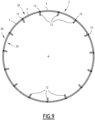
- the wall 2 of at least one or each section 36 is circular.
- Each stiffened plate 4 of the wall is curved along a portion of circle such that the stiffened plate 4 welded together define a circular wall 2.
- Each stiffened plate 4 defines a fraction of the circumference of the wall 2.
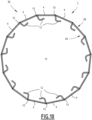
- the wall 2 of at least one or each section 36 is polygonal.
- the stiffened plates 4 are shaped such that the weld beads 10 coincide with the corners of the polygon.
- the stiffened plates 4 are shaped such that the weld beads 10 and the corners of the polygon are circumferentially offset.
- the wall 2 includes for examples stiffened plate 4 and/or non-stiffened plates 4 comprising a first flat potion 16 adjacent the first edge 6 and as second flat portion 18 adjacent the second edge 8, the first flat portion 16 and the second flat portion 18 forming a non-zero angle between them.
- the wall 2 of polygonal shape illustrated on Figure 10 is formed using stiffened plates 4 as illustrated on Figure 5 .
- stiffened plates 4 with other shapes are used, such as stiffened plates as illustrated on Figure 1 - 3 .
- a wall 2 of closed contour in particular a wall 2 of circular contour or polygonal contour, comprises stiffened plates 4 mixed with non-stiffened plates 4.
- a method of manufacturing a wall 2 made of metal plates 4 welded together along edges of the plates 4 comprises the steps of:
- the manufacturing method is in particular operable to manufacture a wall 2 according to the examples described above and illustrated on Figures 1 - 10 .
- the manufacturing method comprises welding the first edge 6 of at least one or each stiffened plate 4 to the second edge 8 of another stiffened plate 4.
- the manufacturing method comprises welding the plates 4 together such that the rims 12 of the stiffened plates 4 protrude on only one of the two sides of the wall 2 (see e.g. Figures 1 - 5 , 9 and 10 ) or protrude on either sides of the wall 2 (see e.g. Figure 6 ).
- the manufacturing method comprises manufacturing a wall extending along a closed contour, for example a circular contour or a polygonal contour (see e.g. Figures 9 and 10 ).
- the method comprises for example welding a series of plates 4 including at least one stiffened plate 4 or consisting of stiffened plates 4, the first edge 6 of each plate 4 being welded to the second edge 8 of the next plate 4, and the first edge 6 of the last plate 4 being welded to the second edge 8 of the first plate 4.
- the plates 4 are welded together such that the rim 12 of each stiffened plate 4 protrudes on the inner side 2A of the wall 2, i.e. the side of the wall 2 oriented towards the inside of the contour.
- the manufacturing method is for example implemented using at least one stiffened plate 4 which is flat between the first edge 6 and the second edge 8 (see e.g. Figure 1 ) and/or at least one stiffened plate 4 which is arched between the first edge 6 and the second edge 8 (see e.g. Figure 4 ), preferably along a portion of circle, and/or at least one stiffened plate 4 which has a first flat portion 16 adjacent the first edge 6 of the stiffened plate 4 and a second flat portion 18 adjacent the second edge 8, the first flat portion 16 and the second flat portion 18 extending at a non-zero angle one relative to the other (see e.g. Figure 3 ).
- At least one each stiffened plate 4 or each stiffened plate 4 comprises a first flat portion 16 adjacent the first edge 6 of the stiffened plate 4 and a second flat portion 18 adjacent the second edge 8, the first flat portion 16 and the second flat portion 18 extending at a non-zero angle one relative to the other.
- the manufacturing method comprises welding the first edge 6 of at least one or each stiffened plate 4 having a first flat portion 16 and a second flat portion 18 to the second edge 8 of another stiffened plate 4 having a first flat portion 16 and a second flat portion 18 such that the first flat portion 16 of the stiffened plate 4 is coplanar with the second flat portion 18 of the other stiffened plate 4 (see e.g. Figure 3 ).
- the manufacturing method comprises forming a wall 2 by welding a series of stiffened plates 4 each provided with a first flat portion 16 and a second flat portion 18, with welding the first edge 6 of each preceding stiffened plate 4 to the second edge 8 of the next stiffened plate 4 such that the first flat portion 16 of the preceding stiffened plate 4 is coplanar with the second flat portion 18 of the next stiffened plate 4 (see e.g. Figure 3 ).
- the manufacturing method comprises welding the first edge 6 of the last stiffened plate 4 to the second edge 8 of the first stiffened plate 4 such that the first flat portion 16 of the last stiffened plate 4 is coplanar with the second flat portion 18 of the first stiffened plate 4
- each stiffened plate 4 is provided with at least one additional stiffener 22, each additional stiffener 22 being welded on a side of the stiffened plate 4 with extending transversely between the first edge 6 and the second edge 8 of the stiffened plate 4, preferably from the rim 12 to the second edge 8 of the stiffened plate 4 (see e.g. Figure 5 ).
- the manufacturing method comprises for example obtaining each stiffened plate 4 provided with a rim 12 by forging metal, by molding metal and/or by forming a metal blank, in particular by shaping, stamping and/or folding the metal blank.
- At least one or each stiffened plate 4 is obtained by forming a blank, in particular a rectangular blank, such as to obtain the stiffened plate 4 provided with the rim 12 extending along a first edge 6 of the stiffened plate 4.
- the forming of the blank comprises for example folding the blank between two parallel opposed edges of the blank such as to form the stiffened plate 4 extending between the fold of the blank and one of the two opposed edges of the blank, and the rim 12 extending between the fold and the other one of the two opposed edges of the blank.
- the step of obtaining each plate 4, in particular each stiffened plate 4, comprises optionally obtaining the blank from a roll, in particular by unrolling the roll.
- the step of obtaining the plates 4 comprises providing a chamfer 14 on the second edge 8 of at least one or each plate 4, in particular at least one or each stiffened plate 4, for example by grinding the second edge 8.
- a stiffened plate 4 is obtained from a roll 40 by unrolling the roll 40 into a blank 42, then forming the blank 42 to define the plate 4 with a rim 12 extending along a first edge 6 of the plate 4, and, optionally, providing a chamfer 14 on a second edge 8 of the plate 4 opposite the first edge 6 of the plate 4.
- the blank 42 is here folded parallel to two opposed edges of the blank 42 such as to form the plate 4 extending between the fold of the blank 42 and one of the edges of the blank, and the rim 12 extending between the fold and the other edge of the blank 42.
- the fold of the blank thus forms the first edge 6 of the plate 4.
- a stiffened plate 4 is obtained from a roll 40 by unrolling the roll 40 into a blank 42, then forming the blank 42 to define the plate 4 with a rim 12 extending along a first edge 6 of the plate 4, here a rim 12 with a double curvature, optionally welding at least one additional stiffener 22 on the plate 4, each additional stiffener 22 extending from the rim 12 to the second edge 8 of the stiffened plate 4, and, optionally, providing a chamfer 14 on a second edge 8 of the plate 4 opposite the first edge 6 of the plate 4.
- each additional fastener 22 adjacent the second edge 8 of the stiffened plate 4 is machined to match the first edge 8 of the stiffened plate 4 to ensure a good positioning when welding the second edge 8 of the stiffened plate 4 to the first edge 6 of another identical stiffened plate 4.
- the metal of the plates 4 is preferably steel. Steel grades used in automotive industry are preferred to the extent they allow lower curvature radius deformations without excessively impairing mechanical properties.
- IF steels ultra-low carbon interstitial free steels
- Suitable IF steels include commercial IF180, IF210, IF220, IF240, IF260, IF280 and IF300 grades.
- the blank 42 or rolls 40 used to obtain the plates 4 have preferably a thickness from 15 to 25 mm, preferably a thickness from 18 to 22 mm, in particular a thickness of 20 mm.
- the blank 42 or rolls has for example a length comprises between 5 and 30 m, typically 10 m and/or a width comprised between 0.5 m and 3.5 m.
- Rolls may be obtained through cold forming or hot forming. Rolling method results in different crystalline forms and therefore different mechanical properties.
- the manufacturing method is suitable for use in any kind of metallic construction and is particularly useful when weight reduction and ease of construction is expected.
- the manufacturing method is suitable for manufacturing of walls of marine structures, in particular floating marine structures, e.g. vessels, platforms, buoys and floaters.
- a wall made of plates welded together including stiffened plates, with stiffeners located on one side of the wall or one either sides of the wall can be obtained with limiting the number of welding operations, as each rim stiffening a stiffened plates are formed integrally in a single piece of metal with the stiffened plate.
- stiffened plates allows using thin plates, which reduces the time that is necessary for welding the plates 4 together edge-to-edge, and reduces the weight of the wall 2.
- the stiffened plate 4 is formed by folding a blank to obtain the stiffened plate 4 with the rim 12 extending along a first edge of the stiffened plate 4, the welding of the first edge of the stiffened plate 4 induces relaxation of internal stress within the crystalline lattice of the metal of the stiffened plate 4 that may have appeared upon folding the blank, hence improving mechanical properties of the stiffened plate 4.
Landscapes
- Engineering & Computer Science (AREA)
- Chemical & Material Sciences (AREA)
- Combustion & Propulsion (AREA)
- Mechanical Engineering (AREA)
- Ocean & Marine Engineering (AREA)
- Architecture (AREA)
- Structural Engineering (AREA)
- Physics & Mathematics (AREA)
- Optics & Photonics (AREA)
- Butt Welding And Welding Of Specific Article (AREA)
Abstract
The method of manufacturing a wall comprises the steps of obtaining the plates (4), the plates (4) including at least one stiffened plate (4) provided with a rim (12) extending along a first edge (6) of the stiffened plate (4) opposite a second edge (8) of the stiffened plate (4), the rim (12) being made integrally in a single piece of metal with the stiffened plate (4), and welding the plates (4) together along edges of the plates (4) such as to form the wall (2), including welding the first edge (6) of each stiffened plate (4) to an edge of another one of the plates (4) such that the rim (12) of the stiffened plate (4) protrudes on one of the two opposed sides of the wall (2) at the junction between the stiffened plate (4) and said other plate (4).
Description
- The present invention relates to the field of metallic constructions, and in particular to the construction of a wall made of a metal plates welded together.
- Metallic floating marine structures such as vessels, platforms, buoys, and floaters may comprise hulls having walls made of metal plates welded together and provided with stiffeners welded to the plates.
- The stiffeners are for example provided as metallic stiffening profiles, which are welded onto the plates to be stiffened. Each stiffening profile has for example a cross-section having a L shape, a T shape, a U shape or H shape.
- The stiffeners allow limiting the thickness of the plates, while preserving the floatability of the structure. Thinner plates result in faster welding and easier shaping, albeit it increases welding works since stiffeners have to be welded onto the plates.
- Welding is traditionally on the critical path for metal constructions since it is usually a lengthy procedure, which requires highly skilled artisans, while risks of defects are significant and may result in final work rebuttal.
- One of the aims of the invention is to propose a method of manufacturing a wall made of metal plates welded together which allows a reduction of the weight whilst being easy and cost-effective.
- To this end, the invention proposes method of manufacturing a wall made of metal plates welded together along edges of the plates, the method comprising the steps of:
- obtaining the plates, the plates including at least one stiffened plate, each stiffened plate being provided with a rim extending along a first edge of the stiffened plate opposite a second edge of the stiffened plate, the rim being made integrally in a single piece of metal with the stiffened plate; and
- welding the plates together along edges of the plates such as to form the wall, including welding the first edge of each stiffened plate to an edge of another one of the plates such that the rim of the stiffened plate protrudes on one of the two opposed sides of the wall at the junction between the stiffened plate and said other plate.
- The wall is manufactured by welding plates including stiffened plates, each stiffened plate being provided with a stiffener formed by a rim provided along an edge of the stiffened plate. Each stiffened plate forms a fraction of the wall and the rim provided on each stiffened plate forms a stiffener.
- A stiffened wall can thus be obtained while limiting the welding operations, as the rim of each stiffened plate is formed integrally in a single piece of material with the stiffened plate and does not need to be welded to the stiffened plate.
- Each stiffened plate provided with a rim integrally formed in a single piece of material with the stiffened plate is obtained easily, for example by forming a blank, in particular by folding a blank to define the stiffened plate and the rim provided along a first edge of the stiffened plate.
- In specific embodiments, the manufacturing method comprising one or several of the following optional features, taken individually or in any technically feasible combination:
- the first edge of at least one or each stiffened plate is welded to the second edge of another stiffened plate;
- the plates are welded together such that the rims of the stiffened plates protrude on only one of the two sides of the wall or protrude on both sides of the wall;
- the wall extends along a closed contour, for example a circular contour or a polygonal contour;
- the plates are assembled together such that the rim of each stiffened plate protrudes on an inner side of the wall;
- at least one or each stiffened plate is flat;
- at least one or each stiffened plate comprises a first flat portion adjacent the first edge and a second flat portion adjacent the second edge, the first flat portion and the second flat portion extending at a non-zero angle one relative to the other.
- at least one or each stiffened plate is arched between the first edge and the second edge, preferably along a portion of circle.
- the rim of at least one stiffened plate has a straight profile and/or the rim of at least one stiffened plate has an arched profile and/or the rim of at least one stiffened plate has a profile with two opposed curvatures;
- at least one or each stiffened plate is provided with at least one additional stiffener, each additional stiffener being welded on a side of the stiffened plate with extending transversely between the first edge and the second edge of the stiffened plate, preferably from the rim to the second edge of the stiffened plate;
- at least one or each stiffened plate is obtained by forming a blank such as to obtain the stiffened plate with the rim protruding form a first edge of the stiffened plate defined by the fold formed into the blank;
- the second edge of at least one or each stiffened plate is chamfered.
- The invention also relates to a method of manufacturing a marine structure comprising a wall, in particular a vessel, a platform, a buoy or a floater, wherein the wall is manufactured according to the manufacturing method as defined above.
- The invention further relates to a wall of a metal construction, in particular a marine structure, the wall being made of metal plates welded together along edges of the plates, the plates including at least one stiffened plate, each stiffened plate being provided with a rim along a first edge of the stiffened plate opposite a second edge of the stiffened plate, the rim being made in a single piece of metal with the stiffened plate, the first edge of the stiffened plate being welded to an edge of another plate such that the rim of the stiffened plate protrudes on one of the two opposed sides of the wall at the junction between the stiffened plate and said other plate.
- In specific embodiments, the wall comprises one or several of the following optional features, taken individually or according to any technically feasible combination:
- the first edge of at least one or each stiffened plate is welded to the second edge of another stiffened plate and/or the second edge of at least one or each stiffened plate is welded to the first edge of another stiffened plate;
- the plates are welded together such that the rims of the stiffened plates protrude only on one of the two sides of the wall or protrude on both sides of the wall;
- the wall extends along a closed contour, for example a circular contour or a polygonal contour;
- at least one or each stiffened plate is flat;
- at least one or each stiffened plate comprises a first flat portion adjacent the first edge and a second flat portion adjacent the second edge, the first flat portion and the second flat portion extending at a non-zero angle one relative to the other;
- at least one or each stiffened plate is arched between the first edg and the second edge, preferably along a portion of circle;
- the rim of at least one stiffened plate has a straight profile and/or the rim of at least one stiffened plate has an arched profile and/or the rim of at least one stiffened plate has a profile with two opposed curvatures separated by a point of inflexion or a straight section;
- at least one or each stiffened plate is provided with at least one additional stiffener, each additional stiffener being welded on a side of the stiffened plate with extending transversely between the first edge and the second edge of the stiffened plate, preferably from the rim to the second edge of the stiffened plate.
- The invention further relates to a marine structure, e.g. a vessel, a platform, a buoy or a floater, in particular a floater of a floating structure of an off-shore wind turbine, the marine structure including at least one wall as defined above.
- The invention and its advantages will be better understood upon reading the following description, which is given solely by way of non-limiting example, and which is made with reference to the appended drawings, in which:
-
Figures 1 - 6 are schematic perspective views and side views of walls manufactured by welding metal plates together; -
Figures 7 and8 are schematic assembled and exploded perspective views of a floater comprising walls manufactured by welding metal plates together; -
Figure 9 is a cross-sectional view of a wall of the floater; -
Figure 10 is a cross-sectional view similar to that ofFigure 9 , illustrating a wall of the floater according to another example; -
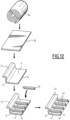
Figure 11 and12 illustrate steps of manufacturing stiffened plates to be used for manufacturing a wall. - The
wall 2 illustrated onFigure 1 is formed of a plurality ofmetal plates 4 arranged edge-to-edge and welded together along their adjacent edges welded. - Each
plate 4 forms a fraction of thewall 2. - Each
plate 4 comprises afirst edge 6 andsecond edge 8 opposite to thefirst edge 6. Thefirst edge 6 and thesecond edge 8 are preferably parallel. - Each
plate 4 has afirst side 4A and asecond side 4B opposite thefirst side 4A. - Each
plate 4 has itsfirst edge 6 welded to thesecond edge 8 of anadjacent plate 4 and/or itssecond edge 8 welded to thefirst edge 6 of anotheradjacent plate 4. -
Welding beads 10 extend along the edges of theplates 4 welded together. - The
plates 4 include at least onestiffened plate 4. Theplates 4 may all be stiffenedplates 4 or may optionally comprise at least one non-stiffenedplate 4. In the following, unless otherwise indicated, aplate 4 designates anyplate 4 of thewall 2, i.e. astiffened plate 4 or anon-stiffened plate 4. - Each
stiffened plate 4 is provided with arim 12 formed integrally in one single piece of metal with thestiffened plate 4. Therim 12 extending along the first edge of theplate 4 acts as a stiffener for thestiffened plate 4. - The
rim 12 of eachstiffened plate 4 protrudes for example from thefirst side 4A of thestiffened plate 4. - Each
stiffened plate 4 has itsfirst edge 6 welded to the second edge of anotherplate 4, such that therim 12 of thisstiffened plate 4 protrudes from thewall 6 along the junction between thestiffened plate 4 and theother plate 4. - The
rim 12 of eachstiffened plate 4 protruding from thewall 2 acts a stiffener for thewall 2 as a whole. - As illustrated on
Figure 1 , thewall 2 is formed of a series of stiffenedplates 4, thefirst edge 6 of eachstiffened plate 4 being welded to thesecond edge 8 of the nextstiffened plate 4 of the series of stiffenedplates 4. - In one embodiment, as illustrated on
Figure 1 , therims 12 of all thestiffened plates 4 protrude on a same side of thewall 2. - In the embodiment illustrated on
Figure 1 , thisfirst edge 6 of the last stiffened plate of the series of stiffenedplates 4 is free. - Advantageously, the
second edge 8 of eachplate 4 welded to thefirst edge 6 of astiffened plate 4 is provided with achamfer 14. - The
chamfer 14 is configured to create a groove between thesecond edge 8 of theplate 4 and thefirst edge 6 of thestiffened plate 4 for welding thesecond edge 8 to thefirst edge 6 with filler material. - The
chamfer 14 is preferably inclined such as to be orientated opposite thefirst side 4A of the stiffenedplate 4 to which the second edge is welded. - In one embodiment, the
second edge 8 of each stiffenedplat 4 is provided with achamfer 14 orientated opposite thefirst side 4A of the stiffenedplate 4. - This allows forming a
wall 2 with fastening a series of stiffenedplates 4 with therim 12 protruding on one side of thewall 2 and thewelding beads 10 being located on the other side of thewall 2, as in the embodiment illustrated onFigure 6 . - A plurality of
flat plates 4 are for example welded to each other such as to be coplanar and to form aflat wall 2, therim 12 of each stiffenedplate 4 protruding from theflat wall 2. - In one embodiment, as illustrated on
Figure 2 , twoflat plates 4 including at least one stiffenedplate 4 provided with arim 12 are welded together with a non-zero angle between theplates 4. - This allows forming a
non-planar wall 2 with at least onerim 12 protruding from thewall 2. In particular, this allows forming awall 2 having facets separated by corners, eachplate 4 defining a respective facet. Even more in particular, this allows forming awall 2 extending along a polygonal contour, eachplate 4 defining a respective facet of thewall 2. - In a particular embodiment, as illustrated on
Figure 2 , two or more flat stiffenedplates 4 are welded together with a non-zero angle between theplates 4 of each pair ofadjacent plates 4. - As illustrated on
Figure 3 , advantageously, at least oneplate 4, in particular at least one stiffenedplate 4, comprises a firstflat portion 16 adjacent thefirst edge 6 and a secondflat portion 18 adjacent thesecond edge 8, the firstflat portion 16 and the secondflat portion 18 defining a non-zero angle between them. - The
plate 4 comprises for example anintermediate fold 20 located between the firstflat portion 16 and the secondflat portion 18. - The
intermediate fold 20 is preferably parallel to thefirst edge 6 and thesecond edge 8 and located at a distance from thefirst edge 6 and at a distance from thesecond edge 8. - In one example, the first
flat portion 16 extends from theintermediate fold 20 to thefirst edge 6 and/or the secondflat portion 18 extends from theintermediate fold 20 to thesecond edge 8. - A
wall 2 is for example obtained with welding a plurality ofplates 4, including at least one stiffenedplate 4, each having a firstflat portion 16 and a secondflat portion 18, with welding thefirst edge 6 of aplate 4 to thesecond edge 6 of anotherplate 4 such that thefirst portion 6 of theplate 4 is coplanar with thesecond potion 18 of theother plate 4. - This allows forming a
wall 2 comprising facets separated by corners in which thewelding beads 10 and the corners are offset along thewall 2. Each facet is defined by afirst potion 16 of one of theplates 4 and thesecond portion 18 of anadjacent plate 4. - In one embodiment, as illustrated on
Figure 4 , at least one or eachplate 4, in particular at least one or each stiffenedplate 4, is arched between thefirst edge 6 and the thesecond edge 8 along a curve, in particular a portion of a circle. - This allows manufacturing a
wall 2 extending along a curve, in particular awall 2 extending along a portion of a circle, in particular acircular wall 2. - As illustrated on
Figure 5 , at least one or each stiffenedplate 4 is optionally provided with at least oneadditional stiffener 22 welded to the stiffenedplate 4 and extending transversely between thefirst edge 6 and thesecond edge 8 of the stiffenedplate 4. - Each
additional stiffener 22 extends for example on thefirst side 4A of the stiffenedplate 4, from therim 12 to thesecond edge 8. - Each
additional stiffener 22 is for example a metal profile. Eachadditional stiffener 22 has for example a cross-section exhibiting a L shape, a T shape, a U shape or a H shape. - As illustrated on
Figure 1 - 5 , therim 12 of each stiffenedplate 4 is for example profiled along thefirst edge 6 of theplate 4. - As illustrated on
Figures 1 - 3 , therim 12 of each stiffenedplate 4 has for example a cross-section that is straight. - The
rim 12 extends for example at an angle comprised between 60 and 120° with respect to the stiffenedplate 4 or a flat portion of the stiffenedplate 4 adjacent thefirst edge 6, e.g. a firstflat portion 16 of the stiffenedplate 4. - As illustrated on
Figures 1 - 3 , therim 12 of each stiffenedplate 4 has a cross-section that is straight and extends at an angle of 90° with respect to the stiffenedplate 4 or the firstflat portion 16 of the stiffenedplate 4. - The
rim 12 of at least one or each stiffenedplate 4 has for example a cross-section that is curved. - In one example, at least one or each stiffened
plate 4 is curved with a first radius of curvature between thefirst edge 6 and thesecond edge 8 and therim 12 is curved with a second radius of curvature strictly greater than the first radius of curvature. - In the example of
Figure 4 , therim 12 of each stiffenedplate 4 has a curvature strictly greater than that of the stiffenedplate 4. - In one example, the
rim 12 of at least one or each stiffenedplate 4 has for example a cross-section that has two opposite curvatures separated by a point of inflexion or a straight section. - As illustrated on
Figure 5 , therim 12 of at least one or each stiffenedplate 4 has for example a cross-section that has two opposite curvatures separated by a point of inflexion. - The shape of the cross-section of the
rim 12 of each stiffenedplate 4 allows tuning the stiffness imparted by therim 12. - Other combinations of the shape of a stiffened
plate 4 and the shape of therim 12 may be contemplated. - For example, a stiffened
plate 4 that is curved may be provided with arim 12 having a straight cross-section. - In the examples of
Figures 1 - 5 , therims 12 of all the stiffenedplates 4 of thewall 2 protrude on a same side of thewall 2. - In a variant, as illustrated on
Figure 6 , therims 12 of the stiffenedplates 4 protrude on either sides of thewall 2. Therim 12 of at least one stiffenedplate 4 protrudes on one side of thewall 2 and therim 12 of at least one stiffenedplate 4 protrudes on the other side of thewall 2. - In the specific embodiment illustrated on
Figure 6 , the stiffenedplates 4 are arranged alternately such that therim 12 of the preceding stiffenedplate 4 protrudes on one side of thewall 2 and the rim of the following stiffenedplate 4 protrudes on the other side of thewall 2. - Other arrangements may be contemplated depending on specific needs for a particular application.
- In each one of the stiffened walls of
Figures 1 - 6 is made of identical stiffenedplates 4. - In one example, a
wall 2 incorporates at least two stiffenedplates 4 which are of different shape and/or are provided withrims 12 of different shapes. This can be contemplated for tuning the overall weight and/or overall stiffness of thewall 2. - A
wall 2 incorporates for example at least one stiffenedplate 4 which is flat between thefirst edge 6 and the second edge 8 (see e.g.Figure 1 ) and/or at least one stiffenedplate 4 which is arched between thefirst edge 6 and the second edge 8 (see e.g.Figure 4 ), preferably along a portion of circle, and/or at least one stiffenedplate 4 which has a firstflat portion 16 adjacent thefirst edge 6 of the stiffenedplate 4 and a secondflat portion 18 adjacent thesecond edge 8, the firstflat portion 16 and the secondflat portion 18 extending at a non-zero angle one relative to the other (see e.g.Figure 3 ). - Similarly, a
wall 2 incorporates for example at least one stiffenedplate 4 provided with arim 12 of straight profile and/or at least one stiffenedplate 4 with arim 12 of curved profile with a curvature on only one side and/or at least one stiffenedplate 4 with arim 12 of curved profile with two opposed curvatures. - A
wall 2 made ofplate 4 welded together including at least one stiffenedplate 4 may be incorporated in a metal construction, in particular in a marine structure, such as a vessel, a platform, a buoy or a floater. - The
structure 30 illustratedFigure 7 and8 comprises atubular body 32 extending along a central axis A and twoend plates 34 closing the axial ends of thebody 32, thebody 32 comprising at least onesection 36 eachsection 36 being formed of a stiffenedwall 2 of circular or polygonal cross-section. - Such a
structure 30 is for example a floater, in particular a floater of a floating structure of an off-shore wind turbine. - The
body 32 comprises for example a plurality ofsections 36 along the central axis A. - Optionally, two
adjacent sections 36 of thebody 32 are separated by anannular stiffener 38. - As illustrated on
Figure 7 and8 , thebody 32 comprises twosections 36 separated by anannular stiffener 38. - The
wall 2 of eachsection 36 extends along a closed contour. - Each
wall 2 is manufactured by welding a series ofplates 4 with welding thefirst edge 6 of eachpreceding plate 4 to the second edge of followingedge 4 and welding thefirst edge 6 of thelast plate 4 to the second edge of thefirst plate 4. Eachplate 4 defines a fraction of the circumference of thewall 2. - Each
wall 2 is formed for example of a series of stiffenedplates 4. Thefirst edge 6 of each preceding stiffenedplate 4 is welded to thesecond edge 8 of the next stiffenedplate 4 and thefirst edge 6 of the last stiffenedplate 4 is welded to thesecond edge 8 of the first stiffenedplate 4. Each stiffenedplate 4 defines a fraction of the circumference of thewall 2. - The
rim 12 of each stiffenedplate 4 protrudes inside thewall 2, i.e. on an inner side of thewall 2. - In one example illustrated on
Figure 9 , thewall 2 of at least one or eachsection 36 is circular. Each stiffenedplate 4 of the wall is curved along a portion of circle such that the stiffenedplate 4 welded together define acircular wall 2. Each stiffenedplate 4 defines a fraction of the circumference of thewall 2. - In a variant illustrated on
Figure 10 , thewall 2 of at least one or eachsection 36 is polygonal. - The stiffened
plates 4 are shaped such that theweld beads 10 coincide with the corners of the polygon. - In a variant, the stiffened
plates 4 are shaped such that theweld beads 10 and the corners of the polygon are circumferentially offset. - In such a variant, the
wall 2 includes for examples stiffenedplate 4 and/ornon-stiffened plates 4 comprising a firstflat potion 16 adjacent thefirst edge 6 and as secondflat portion 18 adjacent thesecond edge 8, the firstflat portion 16 and the secondflat portion 18 forming a non-zero angle between them. - The
wall 2 of polygonal shape illustrated onFigure 10 is formed using stiffenedplates 4 as illustrated onFigure 5 . In other examples, stiffenedplates 4 with other shapes are used, such as stiffened plates as illustrated onFigure 1 - 3 . - The
walls 2 illustrated onFigures 9 and10 consist of stiffenedplates 4. In other examples, awall 2 of closed contour, in particular awall 2 of circular contour or polygonal contour, comprises stiffenedplates 4 mixed withnon-stiffened plates 4. - Different patterns of stiffened
plates 4 andnon-stiffened plates 4 along the circumference of thewall 2 of closed contour can be contemplated as a function of the stiffness that is sought. - A method of manufacturing a
wall 2 made ofmetal plates 4 welded together along edges of theplates 4 comprises the steps of: - obtaining the
plates 4, theplates 4 including at least one stiffenedplate 4; - welding the
plates 4 together along edges thereof such as to form thewall 2, including welding thefirst edge 6 of each stiffenedplate 4 to an edge of anotherplate 4 such that therim 12 of the stiffenedplate 14 protrudes on one of two opposed sides of thewall 2 at the junction between the stiffenedplate 4 and theother plate 4. - The manufacturing method is in particular operable to manufacture a
wall 2 according to the examples described above and illustrated onFigures 1 - 10 . - In one example, the manufacturing method comprises welding the
first edge 6 of at least one or each stiffenedplate 4 to thesecond edge 8 of another stiffenedplate 4. - In one example, the manufacturing method comprises welding the
plates 4 together such that therims 12 of the stiffenedplates 4 protrude on only one of the two sides of the wall 2 (see e.g.Figures 1 - 5 ,9 and10 ) or protrude on either sides of the wall 2 (see e.g.Figure 6 ). - In one example, the manufacturing method comprises manufacturing a wall extending along a closed contour, for example a circular contour or a polygonal contour (see e.g.
Figures 9 and10 ). - The method comprises for example welding a series of
plates 4 including at least one stiffenedplate 4 or consisting of stiffenedplates 4, thefirst edge 6 of eachplate 4 being welded to thesecond edge 8 of thenext plate 4, and thefirst edge 6 of thelast plate 4 being welded to thesecond edge 8 of thefirst plate 4. - In one example, the
plates 4 are welded together such that therim 12 of each stiffenedplate 4 protrudes on theinner side 2A of thewall 2, i.e. the side of thewall 2 oriented towards the inside of the contour. - The manufacturing method is for example implemented using at least one stiffened
plate 4 which is flat between thefirst edge 6 and the second edge 8 (see e.g.Figure 1 ) and/or at least one stiffenedplate 4 which is arched between thefirst edge 6 and the second edge 8 (see e.g.Figure 4 ), preferably along a portion of circle, and/or at least one stiffenedplate 4 which has a firstflat portion 16 adjacent thefirst edge 6 of the stiffenedplate 4 and a secondflat portion 18 adjacent thesecond edge 8, the firstflat portion 16 and the secondflat portion 18 extending at a non-zero angle one relative to the other (see e.g.Figure 3 ). - In one example, at least one each stiffened
plate 4 or each stiffenedplate 4 comprises a firstflat portion 16 adjacent thefirst edge 6 of the stiffenedplate 4 and a secondflat portion 18 adjacent thesecond edge 8, the firstflat portion 16 and the secondflat portion 18 extending at a non-zero angle one relative to the other. - Advantageously, the manufacturing method comprises welding the
first edge 6 of at least one or each stiffenedplate 4 having a firstflat portion 16 and a secondflat portion 18 to thesecond edge 8 of another stiffenedplate 4 having a firstflat portion 16 and a secondflat portion 18 such that the firstflat portion 16 of the stiffenedplate 4 is coplanar with the secondflat portion 18 of the other stiffened plate 4 (see e.g.Figure 3 ). - In particular, the manufacturing method comprises forming a
wall 2 by welding a series of stiffenedplates 4 each provided with a firstflat portion 16 and a secondflat portion 18, with welding thefirst edge 6 of each preceding stiffenedplate 4 to thesecond edge 8 of the next stiffenedplate 4 such that the firstflat portion 16 of the preceding stiffenedplate 4 is coplanar with the secondflat portion 18 of the next stiffened plate 4 (see e.g.Figure 3 ). - Optionally, the manufacturing method comprises welding the
first edge 6 of the last stiffenedplate 4 to thesecond edge 8 of the first stiffenedplate 4 such that the firstflat portion 16 of the last stiffenedplate 4 is coplanar with the secondflat portion 18 of the first stiffenedplate 4 - In one example, at least one or each stiffened
plate 4 is provided with at least oneadditional stiffener 22, eachadditional stiffener 22 being welded on a side of the stiffenedplate 4 with extending transversely between thefirst edge 6 and thesecond edge 8 of the stiffenedplate 4, preferably from therim 12 to thesecond edge 8 of the stiffened plate 4 (see e.g.Figure 5 ). - The manufacturing method comprises for example obtaining each stiffened
plate 4 provided with arim 12 by forging metal, by molding metal and/or by forming a metal blank, in particular by shaping, stamping and/or folding the metal blank. - In one example, at least one or each stiffened
plate 4 is obtained by forming a blank, in particular a rectangular blank, such as to obtain the stiffenedplate 4 provided with therim 12 extending along afirst edge 6 of the stiffenedplate 4. - The forming of the blank comprises for example folding the blank between two parallel opposed edges of the blank such as to form the stiffened
plate 4 extending between the fold of the blank and one of the two opposed edges of the blank, and therim 12 extending between the fold and the other one of the two opposed edges of the blank. - The step of obtaining each
plate 4, in particular each stiffenedplate 4, comprises optionally obtaining the blank from a roll, in particular by unrolling the roll. - Optionally, the step of obtaining the
plates 4 comprises providing achamfer 14 on thesecond edge 8 of at least one or eachplate 4, in particular at least one or each stiffenedplate 4, for example by grinding thesecond edge 8. - As illustrated on
Figure 11 , a stiffenedplate 4 is obtained from aroll 40 by unrolling theroll 40 into a blank 42, then forming the blank 42 to define theplate 4 with arim 12 extending along afirst edge 6 of theplate 4, and, optionally, providing achamfer 14 on asecond edge 8 of theplate 4 opposite thefirst edge 6 of theplate 4. - The blank 42 is here folded parallel to two opposed edges of the blank 42 such as to form the
plate 4 extending between the fold of the blank 42 and one of the edges of the blank, and therim 12 extending between the fold and the other edge of the blank 42. The fold of the blank thus forms thefirst edge 6 of theplate 4. - As illustrated on
Figure 12 , a stiffenedplate 4 is obtained from aroll 40 by unrolling theroll 40 into a blank 42, then forming the blank 42 to define theplate 4 with arim 12 extending along afirst edge 6 of theplate 4, here arim 12 with a double curvature, optionally welding at least oneadditional stiffener 22 on theplate 4, eachadditional stiffener 22 extending from therim 12 to thesecond edge 8 of the stiffenedplate 4, and, optionally, providing achamfer 14 on asecond edge 8 of theplate 4 opposite thefirst edge 6 of theplate 4. - As illustrated on
Figure 12 , the end of eachadditional fastener 22 adjacent thesecond edge 8 of the stiffenedplate 4 is machined to match thefirst edge 8 of the stiffenedplate 4 to ensure a good positioning when welding thesecond edge 8 of the stiffenedplate 4 to thefirst edge 6 of another identical stiffenedplate 4. - The metal of the
plates 4 is preferably steel. Steel grades used in automotive industry are preferred to the extent they allow lower curvature radius deformations without excessively impairing mechanical properties. - Examples of appropriate steel grades include ultra-low carbon interstitial free steels (aka. "IF" steels), which are normally alloyed with manganese, silicon and phosphorous. Suitable IF steels include commercial IF180, IF210, IF220, IF240, IF260, IF280 and IF300 grades.
- The blank 42 or rolls 40 used to obtain the
plates 4 have preferably a thickness from 15 to 25 mm, preferably a thickness from 18 to 22 mm, in particular a thickness of 20 mm. - The blank 42 or rolls has for example a length comprises between 5 and 30 m, typically 10 m and/or a width comprised between 0.5 m and 3.5 m.
- Rolls may be obtained through cold forming or hot forming. Rolling method results in different crystalline forms and therefore different mechanical properties.
- The manufacturing method is suitable for use in any kind of metallic construction and is particularly useful when weight reduction and ease of construction is expected.
- The manufacturing method is suitable for manufacturing of walls of marine structures, in particular floating marine structures, e.g. vessels, platforms, buoys and floaters.
- Owing to the invention, a wall made of plates welded together including stiffened plates, with stiffeners located on one side of the wall or one either sides of the wall, can be obtained with limiting the number of welding operations, as each rim stiffening a stiffened plates are formed integrally in a single piece of metal with the stiffened plate.
- The use of stiffened plates allows using thin plates, which reduces the time that is necessary for welding the
plates 4 together edge-to-edge, and reduces the weight of thewall 2. - When the stiffened
plate 4 is formed by folding a blank to obtain the stiffenedplate 4 with therim 12 extending along a first edge of the stiffenedplate 4, the welding of the first edge of the stiffenedplate 4 induces relaxation of internal stress within the crystalline lattice of the metal of the stiffenedplate 4 that may have appeared upon folding the blank, hence improving mechanical properties of the stiffenedplate 4.
Claims (19)
- Method of manufacturing a wall (2) made of metal plates (4) welded together along edges of the plates (4), the method comprising the steps of :- obtaining the plates (4), the plates (4) including at least one stiffened plate (4), each stiffened plate (4) being provided with a rim (12) extending along a first edge (6) of the stiffened plate (4) opposite a second edge (8) of the stiffened plate (4), the rim (12) being made integrally in a single piece of metal with the stiffened plate (4); and- welding the plates (4) together along edges of the plates (4) such as to form the wall (2), including welding the first edge (6) of each stiffened plate (4) to an edge of another one of the plates (4) such that the rim (12) of the stiffened plate (4) protrudes on one of the two opposed sides of the wall (2) at the junction between the stiffened plate (4) and said other plate (4).
- Method according to claim 1, wherein the first edge (6) of at least one or each stiffened plate (4) is welded to the second edge (8) of another stiffened plate (4).
- Method according to claim 1 or 2, wherein the wall (2) extends along a closed contour, for example a circular contour or a polygonal contour.
- Method according to any one of the preceding claims, wherein the plates are assembled together such that the rim (12) of each stiffened plate (4) protrudes on an inner side of the wall (2).
- Method according to any one of the preceding claims, wherein at least one or each stiffened plate (4) comprises a first flat portion (16) adjacent the first edge (6) and a second flat portion (18) adjacent the second edge (8), the first flat portion (16) and the second flat portion (18) extending at a non-zero angle one relative to the other.
- Method according to any one of the preceding claims, wherein at least one or each stiffened plate (4) is arched between the first edge (6) and the second edge (8), preferably along a portion of circle.
- Method according to any one of the preceding claims, wherein the rim (12) of at least one stiffened plate (4) has a straight profile and/or the rim (12) of at least one stiffened plate (4) has an arched profile and/or the rim (12) of at least one stiffened plate (4) has a profile with two opposed curvatures.
- Method according to any one of the preceding claims, wherein at least one or each stiffened plate (4) is provided with at least one additional stiffener (22), each additional stiffener (22) being welded on a side of the stiffened plate (4) with extending transversely between the first edge (6) and the second edge (8) of the stiffened plate (4), preferably from the rim (12) to the second edge (8) of the stiffened plate (4).
- Method according to any one of the preceding claims, wherein at least one or each stiffened plate (4) is obtained by forming a blank such as to obtain the stiffened plate (4) with the rim (12) protruding form a first edge (6) of the stiffened plate (4) defined by the fold formed into the blank.
- Method according to any one of the preceding claims, wherein the second edge (8) of at least one or each stiffened plate (4) is chamfered.
- Method of manufacturing a marine structure comprising a wall, in particular a vessel, a platform, a buoy or a floater, wherein the wall is manufactured according to the manufacturing method of any one of the preceding claims.
- Wall (2) of a metal construction, in particular a marine structure, the wall (2) being made of metal plates (4) welded together along edges of the plates (4), the plates (4) including at least one stiffened plate (4), each stiffened plate (4) being provided with a rim (12) along a first edge (6) of the stiffened plate (4) opposite a second edge (8) of the stiffened plate (4), the rim (12) being made in a single piece of metal with the stiffened plate (4), the first edge (6) of the stiffened plate (4) being welded to an edge of another plate (4) such that the rim (12) of the stiffened plate (4) protrudes on one of the two opposed sides of the wall at the junction between the stiffened plate (4) and said other plate (4).
- Wall (2) according to claim 12, wherein the first edge (6) of at least one or each stiffened plate (4) is welded to the second edge (8) of another stiffened plate (4) and/or the second edge (8) of at least one or each stiffened plate (4) is welded to the first edge (6) of another stiffened plate (4).
- Wall (2) according to claim 12 or 13, wherein the wall (2) extends along a closed contour, for example a circular contour or a polygonal contour.
- Wall (2) according to any one of claims 12 - 13, wherein at least one or each stiffened plate (4) comprises a first flat portion (16) adjacent the first edge (6) and a second flat portion (18) adjacent the second edge (8), the first flat portion (16) and the second flat portion (18) extending at a non-zero angle one relative to the other.
- Wall (2) according to any one of claims 12 - 16, wherein at least one or each stiffened plate (4) is arched between the first edge (6) and the second edge (8), preferably along a portion of circle.
- Wall (2) according to any one of claims 12-16, wherein the rim (12) of at least one stiffened plate (4) has a straight profile and/or the rim (12) of at least one stiffened plate (4) has an arched profile and/or the rim (12) of at least one stiffened plate (4) has a profile with two opposed curvatures separated by a point of inflexion or a straight section.
- Wall (2) according to any one of claims 12 - 17, wherein at least one or each stiffened plate (4) is provided with at least one additional stiffener (22), each additional stiffener (22) being welded on a side of the stiffened plate (4) with extending transversely between the first edge (6) and the second edge (8) of the stiffened plate (4), preferably from the rim (12) to the second edge (8) of the stiffened plate (4).
- Marine structure, e.g. a vessel, a platform, a buoy or a floater, in particular a floater of a floating structure of an off-shore wind turbine, the marine structure including at least one wall (2) according to any one of claims 12 - 18.
Priority Applications (4)
| Application Number | Priority Date | Filing Date | Title |
|---|---|---|---|
| EP22306836.2A EP4382408A1 (en) | 2022-12-09 | 2022-12-09 | Method of manufacturing a wall made of metal plates welded together and corresponding wall |
| KR1020257022868A KR20250121569A (en) | 2022-12-09 | 2023-12-08 | Method for manufacturing a wall by welding metal plates and a corresponding wall |
| EP23821594.1A EP4630317A1 (en) | 2022-12-09 | 2023-12-08 | Method of manufacturing a wall made of metal plates welded together and corresponding wall |
| PCT/EP2023/084901 WO2024121390A1 (en) | 2022-12-09 | 2023-12-08 | Method of manufacturing a wall made of metal plates welded together and corresponding wall |
Applications Claiming Priority (1)
| Application Number | Priority Date | Filing Date | Title |
|---|---|---|---|
| EP22306836.2A EP4382408A1 (en) | 2022-12-09 | 2022-12-09 | Method of manufacturing a wall made of metal plates welded together and corresponding wall |
Publications (1)
| Publication Number | Publication Date |
|---|---|
| EP4382408A1 true EP4382408A1 (en) | 2024-06-12 |
Family
ID=84602669
Family Applications (2)
| Application Number | Title | Priority Date | Filing Date |
|---|---|---|---|
| EP22306836.2A Withdrawn EP4382408A1 (en) | 2022-12-09 | 2022-12-09 | Method of manufacturing a wall made of metal plates welded together and corresponding wall |
| EP23821594.1A Pending EP4630317A1 (en) | 2022-12-09 | 2023-12-08 | Method of manufacturing a wall made of metal plates welded together and corresponding wall |
Family Applications After (1)
| Application Number | Title | Priority Date | Filing Date |
|---|---|---|---|
| EP23821594.1A Pending EP4630317A1 (en) | 2022-12-09 | 2023-12-08 | Method of manufacturing a wall made of metal plates welded together and corresponding wall |
Country Status (3)
| Country | Link |
|---|---|
| EP (2) | EP4382408A1 (en) |
| KR (1) | KR20250121569A (en) |
| WO (1) | WO2024121390A1 (en) |
Citations (5)
| Publication number | Priority date | Publication date | Assignee | Title |
|---|---|---|---|---|
| GB1473666A (en) * | 1974-05-17 | 1977-05-18 | March R | Curved moulds boats and like structures |
| US6058865A (en) * | 1997-02-18 | 2000-05-09 | Thibeault; Sylvio | Extrusion-sections for boats |
| JP2006160229A (en) * | 2004-12-09 | 2006-06-22 | Masayoshi Hamanaka | Joining method of steel sheet |
| US20100101478A1 (en) * | 2008-10-29 | 2010-04-29 | Samuel Manu-Tech Inc. | Marine Vessel Panel Assembly And Roll-Formed Panel For Same |
| US8136464B1 (en) * | 2008-08-18 | 2012-03-20 | Barbier Brian K | C-fast system |
-
2022
- 2022-12-09 EP EP22306836.2A patent/EP4382408A1/en not_active Withdrawn
-
2023
- 2023-12-08 KR KR1020257022868A patent/KR20250121569A/en active Pending
- 2023-12-08 EP EP23821594.1A patent/EP4630317A1/en active Pending
- 2023-12-08 WO PCT/EP2023/084901 patent/WO2024121390A1/en not_active Ceased
Patent Citations (5)
| Publication number | Priority date | Publication date | Assignee | Title |
|---|---|---|---|---|
| GB1473666A (en) * | 1974-05-17 | 1977-05-18 | March R | Curved moulds boats and like structures |
| US6058865A (en) * | 1997-02-18 | 2000-05-09 | Thibeault; Sylvio | Extrusion-sections for boats |
| JP2006160229A (en) * | 2004-12-09 | 2006-06-22 | Masayoshi Hamanaka | Joining method of steel sheet |
| US8136464B1 (en) * | 2008-08-18 | 2012-03-20 | Barbier Brian K | C-fast system |
| US20100101478A1 (en) * | 2008-10-29 | 2010-04-29 | Samuel Manu-Tech Inc. | Marine Vessel Panel Assembly And Roll-Formed Panel For Same |
Also Published As
| Publication number | Publication date |
|---|---|
| EP4630317A1 (en) | 2025-10-15 |
| KR20250121569A (en) | 2025-08-12 |
| WO2024121390A1 (en) | 2024-06-13 |
Similar Documents
| Publication | Publication Date | Title |
|---|---|---|
| US10315698B2 (en) | Sixteen-cornered strengthening member for vehicles | |
| US9944323B2 (en) | Twenty-four-cornered strengthening member for vehicles | |
| US9828034B2 (en) | Vehicle bodywork structure device | |
| US6227609B1 (en) | Vehicle door reinforcing beam and method of making it | |
| US6632057B1 (en) | Fixing unit with an end imprint in a threaded terminal portion | |
| EP1054811A1 (en) | Expanded cans | |
| CA2684066C (en) | Marine vessel panel assembly and roll-formed panel for same | |
| US20120222284A1 (en) | Seat Track Assembly | |
| US7014274B2 (en) | Sheet-steel wheel rim with optimized profile | |
| US20230117003A1 (en) | Steel rocker energy absorption load path development for rechargeable energy storage system protection | |
| US11634205B2 (en) | Frame component and method for producing a frame component, frame and fuselage structure for an aircraft | |
| US20050210820A1 (en) | Frame and method for fabricating the same | |
| EP4630317A1 (en) | Method of manufacturing a wall made of metal plates welded together and corresponding wall | |
| KR20070085344A (en) | Building panels and building structures | |
| GB2102465A (en) | Rolled metal beam | |
| KR20120065355A (en) | Ball roller bearing | |
| JP7158700B2 (en) | Modular stern duct assembly method, modular stern duct and vessel | |
| EP4183636B1 (en) | Impact absorption member | |
| US20080141532A1 (en) | Manufacturing Process for a Tubeless Wheel Rim for Off Road Vehicles, Rim Obtained Through an Off-Road Vehicle Process | |
| JP2019172024A5 (en) | ||
| US11642712B1 (en) | Method of manufacturing vehicle body structure component to include reinforced regions | |
| EP2836420B1 (en) | Marine hull and marine vessel | |
| JP2002274483A (en) | Cell guide of container ship and method of manufacturing its cell guide | |
| US20040144469A1 (en) | Tire for heavy vehicle | |
| KR20250103709A (en) | Absence of skeleton |
Legal Events
| Date | Code | Title | Description |
|---|---|---|---|
| PUAI | Public reference made under article 153(3) epc to a published international application that has entered the european phase |
Free format text: ORIGINAL CODE: 0009012 |
|
| STAA | Information on the status of an ep patent application or granted ep patent |
Free format text: STATUS: THE APPLICATION HAS BEEN PUBLISHED |
|
| AK | Designated contracting states |
Kind code of ref document: A1 Designated state(s): AL AT BE BG CH CY CZ DE DK EE ES FI FR GB GR HR HU IE IS IT LI LT LU LV MC ME MK MT NL NO PL PT RO RS SE SI SK SM TR |
|
| STAA | Information on the status of an ep patent application or granted ep patent |
Free format text: STATUS: THE APPLICATION IS DEEMED TO BE WITHDRAWN |
|
| 18D | Application deemed to be withdrawn |
Effective date: 20241213 |