EP4382318A1 - Detection of tire radius mismatch - Google Patents
Detection of tire radius mismatch Download PDFInfo
- Publication number
- EP4382318A1 EP4382318A1 EP23213828.9A EP23213828A EP4382318A1 EP 4382318 A1 EP4382318 A1 EP 4382318A1 EP 23213828 A EP23213828 A EP 23213828A EP 4382318 A1 EP4382318 A1 EP 4382318A1
- Authority
- EP
- European Patent Office
- Prior art keywords
- tire
- tires
- temperature values
- radius
- temperature
- Prior art date
- Legal status (The legal status is an assumption and is not a legal conclusion. Google has not performed a legal analysis and makes no representation as to the accuracy of the status listed.)
- Granted
Links
Images




Classifications
-
- B—PERFORMING OPERATIONS; TRANSPORTING
- B60—VEHICLES IN GENERAL
- B60C—VEHICLE TYRES; TYRE INFLATION; TYRE CHANGING; CONNECTING VALVES TO INFLATABLE ELASTIC BODIES IN GENERAL; DEVICES OR ARRANGEMENTS RELATED TO TYRES
- B60C11/00—Tyre tread bands; Tread patterns; Anti-skid inserts
- B60C11/24—Wear-indicating arrangements
- B60C11/246—Tread wear monitoring systems
-
- G—PHYSICS
- G07—CHECKING-DEVICES
- G07C—TIME OR ATTENDANCE REGISTERS; REGISTERING OR INDICATING THE WORKING OF MACHINES; GENERATING RANDOM NUMBERS; VOTING OR LOTTERY APPARATUS; ARRANGEMENTS, SYSTEMS OR APPARATUS FOR CHECKING NOT PROVIDED FOR ELSEWHERE
- G07C5/00—Registering or indicating the working of vehicles
- G07C5/08—Registering or indicating performance data other than driving, working, idle, or waiting time, with or without registering driving, working, idle or waiting time
- G07C5/0808—Diagnosing performance data
-
- B—PERFORMING OPERATIONS; TRANSPORTING
- B60—VEHICLES IN GENERAL
- B60C—VEHICLE TYRES; TYRE INFLATION; TYRE CHANGING; CONNECTING VALVES TO INFLATABLE ELASTIC BODIES IN GENERAL; DEVICES OR ARRANGEMENTS RELATED TO TYRES
- B60C23/00—Devices for measuring, signalling, controlling, or distributing tyre pressure or temperature, specially adapted for mounting on vehicles; Arrangement of tyre inflating devices on vehicles, e.g. of pumps or of tanks; Tyre cooling arrangements
-
- B—PERFORMING OPERATIONS; TRANSPORTING
- B60—VEHICLES IN GENERAL
- B60C—VEHICLE TYRES; TYRE INFLATION; TYRE CHANGING; CONNECTING VALVES TO INFLATABLE ELASTIC BODIES IN GENERAL; DEVICES OR ARRANGEMENTS RELATED TO TYRES
- B60C23/00—Devices for measuring, signalling, controlling, or distributing tyre pressure or temperature, specially adapted for mounting on vehicles; Arrangement of tyre inflating devices on vehicles, e.g. of pumps or of tanks; Tyre cooling arrangements
- B60C23/20—Devices for measuring or signalling tyre temperature only
Definitions
- Tires on vehicles such as tractor/trailers used to haul freight and other items may be subject to significant wear over time. Given the significant amount of weight that tires can bear on a vehicle such as a tractor/trailer and given the speeds at which such vehicles travel, excessive wear of tires is possible, which can be undesirable, such as by being detrimental to the environment.
- the invention relates to a system in accordance with claims 1 or 12 respectively, and to a method in accordance with claims 13 or 14 respectively.
- CAN bus is an abbreviation for controller area network.
- Carcass means the tire structure apart from the belt structure, tread, undertread, and sidewall rubber over the plies, but including the beads.
- “Footprint” means the contact patch or area of contact created by the tire tread with a flat surface, such as the ground, as the tire rotates or rolls.
- Ring and radially mean lines or directions that are perpendicular to the axis of rotation of the tire.
- TPMS means a tire pressure monitoring system, which is an electronic system that measures the internal pressure of a tire and is capable of communicating the pressure to a processor that is mounted on the vehicle and/or is in electronic communication with electronic systems of the vehicle.
- Various embodiments are set forth for determining whether a tire radius mismatch exists between two tires mounted on a dual wheel hub.
- data is obtained from sensors in the tires that indicates the tire temperature, tire pressure, and potentially other parameters.
- Data may also be obtained from other systems in a vehicle from a CAN bus.
- a determination may be made from the data as to whether a tire radius mismatch exists between the tires mounted on the dual wheel hub.
- Such a tire radius mismatch can result in undue wear on the tires. Identification of such a tire radius mismatch allows for corrective action to be taken such as tire replacement or other action.
- first various elements are introduced followed by a discussion of the operation of the same.
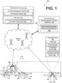
- the networked environment 100 includes a computing environment 103 and a network 106.
- the computing environment 103 is in data communication with computing devices 109 that are mounted, for example, on a vehicle 113 by way of the network 106.
- the networked environment 100 further includes a client device 111 that comprises a computing device as will be described.
- the vehicle includes a plurality of sensors 116, each sensor 116 being positioned on the inside of a respective one of a plurality of tires 119 of the vehicle 113.
- the sensors 116 are employed as part of a tire pressure monitoring system (TPMS) as will be described.
- TPMS tire pressure monitoring system
- Some of the tires 119 are mounted on dual wheel hubs 120 such as in the case where the vehicle 113 comprises an eighteen-wheel tractor-trailer as depicted in FIG. 1 .
- the vehicle 113 also includes, for example, a CAN bus 121 that facilitates data communication between various systems on the vehicle 113.
- the computing device(s) are coupled to the CAN bus 121 and can communicate with systems included on the CAN bus 121.
- the computing environment 103 may comprise, for example, a server computer or any other system providing computing capability.
- the computing environment 103 may employ a plurality of computing devices that may be arranged, for example, in one or more server banks or computer banks or other arrangements. Such computing devices may be located in a single installation or may be distributed among many different geographical locations.
- the computing environment 103 may include a plurality of computing devices that together may comprise a hosted computing resource, a grid computing resource and/or any other distributed computing arrangement.
- the computing environment 103 may correspond to an elastic computing resource where the allotted capacity of processing, network, storage, or other computing-related resources may vary over time.
- Various applications and/or other functionality may be executed in the computing environment 103 according to various embodiments.
- various data is stored in a data store 123 that is accessible to the computing environment 103.
- the data store 123 may be representative of a plurality of data stores 123 as can be appreciated.
- the data stored in the data store 123 is associated with the operation of the various applications and/or functional entities described below.
- the components executed on the computing environment 103 include a tire fleet management system 126, and other applications, services, processes, systems, engines, or functionality not discussed in detail herein.
- the tire fleet management system 126 is employed to track the location and status of fleet of tires 119 mounted on a plurality of vehicles 113. Such a tire fleet management system 126 may track hundreds if not thousands of tires 119 on many vehicles 113.
- the tire fleet management system 126 indicates to operators when tires 119 may need to be serviced, replaced, or the tire fleet management system 126 may provide other information.
- the various components of the tire fleet management system 126 comprise a tire mismatch system 129.
- the tire mismatch system 129 is executed to detect whether a tire diameter mismatch exists between two tires that are mounted adjacent to each other on a dual wheel hub 120 as will be described in further detail below.
- each of the tire sensor data records 133 includes an instance of a given reading of sensor data from a respective one of the tires 119 and potentially information from a CAN bus 121 on the vehicle 113 at a given time as will be described.
- the information from the CAN bus 121 on the vehicle 113 may comprise, for example, times when the brakes of the vehicle 113 have been engaged, torque generated by the engine and applied to wheels/tires, state of the steering wheel or whether the vehicle 113 is turning or is being driven straight, and many other information about the operation of the vehicle 113.
- the information from the CAN bus 121 may be communicated to the tire fleet management system 126 for use in evaluating the status of the tires 119 in the fleet.
- the computing devices 109 may obtain information from the CAN bus 121 and include such information in the tire sensor data records 133.
- the network 106 may comprise, for example, the Internet, intranets, extranets, wide area networks (WANs), local area networks (LANs), wired networks, wireless networks, cellular networks, satellite networks, cable networks, Wifi networks, or other suitable networks, etc., or any combination of two or more such networks.
- WANs wide area networks
- LANs local area networks
- wired networks wireless networks
- wireless networks cellular networks
- satellite networks satellite networks
- cable networks cable networks
- Wifi networks or other suitable networks, etc., or any combination of two or more such networks.
- the computing device 109 comprises a processor circuit that executes, for example, a tire pressure monitoring system (TPMS) 136.
- TPMS tire pressure monitoring system
- the computing device 109 may be integrated with other systems in the vehicle 113.
- the vehicle comprises a tractor-trailer
- the computing device 109 may be located on the back of the trailer so as to be within range of wireless communication with the sensors 116 in the tires 119 of the trailer.
- the computing device 109 also includes a communication system 139 to facilitate communication with the tire fleet management system 126 over the network.
- the computing device 109 may include appropriate communications capabilities to link to a cellular network, Wifi network, or other network communications capabilities.
- the TPMS 136 communicates with the sensors 116 periodically to obtain information from the sensors 116, where such information includes a sensor identifier, pressure values, temperature values, and potentially other information from the sensors 116.
- information is stored, for example, as tire sensor data records 133 in a memory associated with the computing device 109.
- each tire sensor data record 133 includes information obtained from a single readout of a given sensor 116.
- the TPMS 136 includes a timestamp in each tire sensor data record 133 to indicate when the pressure and temperature values were read from a respective sensor 116.
- the sensors 116 may generate a timestamp at the time it provides the sensor data to the TPMS 136.
- tire mismatch system 129 may be implemented locally on the computing device 109 where the detection of whether a tire diameter mismatch exists between two tires that are mounted adjacent to each other on a dual wheel hub 120 is performed local to the vehicle 113.
- the client device 111 may be configured to execute various applications such as a fleet management interface application 143.
- the fleet management interface application 143 may be executed in the client device 111, for example, to access network content served up by the tire fleet management system 126 and/or other servers, thereby rendering a user interface 146 on a display device.
- the tire fleet management system 126 includes a web server, although other server technologies may be employed.
- the fleet management interface application 143 may comprise, for example, a browser or a dedicated application, and the user interface 146 may comprise a network page such as a web page or an application screen.
- the client device 111 may be configured to execute applications beyond the fleet management interface application 143 such as, for example, email applications, word processors, spreadsheets, and/or other applications.
- the fleet management interface application 143 facilitates interaction with the tire fleet management system 126.
- the tire fleet management system 126 encodes the user interface 146 that is sent to the fleet management interface application 143 and is rendered on a display device as can be appreciated.
- the user interface 146 includes an indication 149 that a tire radius mismatch exists between the first and second tires 119 when the tire radius difference of the first and second tires is detected as will be described.
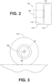
- a dual wheel hub assembly 153 that includes a first and second tire 119 mounted on a dual wheel hub 120. As such, the first and second tires 119 are positioned adjacent to each other. Each tire includes a sensor 116 that can provide measurements of pressure, temperature, and other characteristics of the tire as part of a TPMS system as can be appreciated. Also, the dual wheel hub assembly 153 includes a brake 156 as can be appreciated.
- FIG. 3 shown is side view of a tire 119 as mounted on a dual wheel hub 120.
- the footprint of the tire 119 is the contact patch or area of contact by the tire 119 with a flat surface such as the ground, a portion of the tire 119 is deflected.
- a radius of the tire at the shortest distance from the axis of rotation of the tire 119 and the point of greatest deflection of the footprint is a deflected radius DR of the tire.
- a radius R of the tire 119 is specified as the distance from the axis of rotation to an outer edge of the tire 119 outside of the footprint.
- the radius R can differ from one tire 119 to the next tire 119 due to tread wear. That is to say, a tire 119 that has a greater amount of tread wear will have a smaller radius R than a newer tire 119 with little or no wear.
- Each of the thermal footprints 163a-d show a temperature distribution of the portion of a tire 119 that forms a footprint of a given tire 119.
- the deflected radius DR will be the same for both tires 119 regardless of the radius R of each tire 119 as equilibrium is reached between the load, tires 119, and other elements.
- the load on the pair of tires 119 is 11,350 foot-pounds (5675 foot-pounds x 2) at 100 PSI moving at 50 mph.
- the theoretical thermal footprints 163a and 163b are depicted for tires 119 that are both new, where each of the tires 119 in the pair has the same radius R.
- the deflected radius DR is 474.8 mm for both of the tires 119 that theoretically exist on a given dual wheel hub 120.
- the temperature distribution of each of the thermal footprints 163a and 163b are similar given the fact that the tires 119 have the same radius R.
- the theoretical thermal footprints 163c and 163d are depicted for tires 119 that are mismatched in that the respective radius R of each of the tires 119 is different.
- the thermal footprint 163c is much larger than the thermal footprint 163d due to the fact that the tire 119 corresponding to the thermal footprint 163c has a larger radius R than the tire 119 corresponding to the thermal footprint 163d. Also, as shown, the tire 119 corresponding to the thermal footprint 163c has more areas that reach higher temperatures. This is likely due to the fact that the thermal footprint 163c is larger and that the corresponding tire 119 bears more weight than the tire 119 corresponding to the thermal footprint 163d. This fact likely results in a higher rate of wear of such tire 119, thereby resulting in a shorter useful life of the tire 119 until the tread has worn to maximum recommended limits.
- the wear pattern associated with the thermal footprint 163d is much different, resulting in further wear of the tread of the corresponding tire 119 that may be uneven. Given that the radius R of the respective tires 119 are different for the thermal footprints 163c/d, then the wear of the respective tires 119 differs relative to the tires 119 corresponding to the thermal footprints 163a/b of FIG. 4A .
- FIGS. 5A and 5B shown are finite element analysis renderings 166a, 166b of theoretical thermal footprints 169a-d of two different pairs of tires 119 ( FIG. 1 ) that would be mounted on a dual wheel hub 120 ( FIG. 2 ).
- Each of the thermal footprints 169a-d show a temperature distribution of the portion of a tire 119 that forms a footprint of a given tire 119 as depicted in FIGS. 4A and 4B .
- the deflected radius DR will be the same for both tires 119 regardless of the radius R of each tire 119 as equilibrium is reached between the load, tires 119, and other elements.
- the load on the pair of tires 119 is 11,350 foot-pounds (5675 foot-pounds x 2) at 100 PSI moving at 50 mph.
- the deflected radius DR for the thermal footprints 169a/b is 475.66 mm.
- the deflected radius DR for the thermal footprints 169c/d is 470.63 mm.
- the finite element analysis renderings 160a/b and 166a/b show that in situations where there is a mismatch in the radius R of two tires 119 installed on a dual wheel hub 120, more heat is generated in the tire 119 having the greatest radius R of the two tires 119.
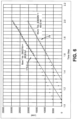
- curves that depict the loads that are born by the individual tires 119 ( FIG. 1 ) on a dual wheel hub 120 ( FIG. 2 ).
- FIG. 7 shown are temperature profiles of two tires 119, denoted herein as tires 119a and 119b, generated using finite element analysis.
- the tire 119a has a radius R that is greater than the radius R of the tire 119b.
- the tire 119a bears approximately 6638 foot-pounds at 100 PSI and the tire 119b bears approximately 4633 foot-pounds at 100 PSI. Given its greater size and the fact that it bears a greater amount of weight, the material of the tire 119a runs at higher temperatures.
- the areas where belts and other such structures are included in the tire 119a are subject to greater frictional forces and experience higher temperatures than do the counterpart structures in the tire 119b.
- the resulting temperature of the cavity of the tire 119a is 72.7 degrees Celsius and the temperature of the cavity of the tire 119b is 53.7 degrees Celsius.
- the sensors 116 generate readings of temperature, pressure, and potentially other parameters associated with a respective one of the tires 119.
- the TPMS 136 executed in a computing device 109 communicates with the sensors 116 to obtain the pressure, temperature, and other readings from the respective sensors 116.
- the sensors 116 generate the full tire sensor data record 133 including sensor identifier information, a timestamp, pressure, temperature, and potentially other parameters.
- the sensors 116 transmit the same to the TPMS 136 executed by the computing device 109.
- the sensors 116 may transmit sensor identifier information, pressure information, temperature information, and potentially other parameters to the TPMS 136 in the computing device 109, and the computing device 109 may package such information in the form of a tire sensor data record 133 with a timestamp.
- the tire sensor data records 133 are temporarily stored in the computing device 109.
- the communication system 139 periodically transmits the tire sensor data records 133 to the tire fleet management system 126 where they are stored in the data store 123.
- the tire sensor data records 133 may remain in a memory of the computing device 109 for purposes of analysis by the tire mismatch system 129. In such a case, a copy of the tire sensor data records 133 may still be transmitted to the tire fleet management system 126.
- the tire fleet management system 126 is executed in the computing environment 103 to track the status of tires 119 on multiple vehicles 113.
- the tire mismatch system 129 is executed as part of the tire fleet management system 126 to detect when there is a tire radius difference between first and second tires 119 positioned adjacent to each other on a dual wheel hub 120. Such a tire radius difference is identified so that corrective action may be taken to prevent accelerated wear of the tread of the tires 119 by tire replacement or other action.
- the status of tires 119 is maintained on the tire fleet management system 126.
- the fleet management interface application 143 may request a user interface 146 to review the status of the tires 119 in the fleet, where the user interface 146 indicates when a tire radius mismatch is detected.
- the tire fleet management system 126 encodes for display an indication that a tire radius mismatch exists between the first and second tires 119 on a given dual wheel hub 120 of a respective vehicle 113 when it has been detected that the tire radius difference exists.
- the indication may be encoded, for example, as part of a network page such as a web page or some other graphical user interface.
- the network page or other interface that embodies the indication is transmitted to the client device 111 and rendered on a display device as the user interface 149.
- the indication may be any interface mechanism that shows that the tire radius mismatch exists between the respective two tires 119 for a given vehicle 113.
- mismatched tires 119 may be represented by user interface components that involve blinking, highlighting with a predefined color, or other indication.
- the tire mismatch system 129 accesses temperature values or other values from the tire sensor data records 133.
- the existence of a tire radius difference is determined based on the temperature values from the tire sensor data records 133 from the respective first and second tires 119 on the dual wheel hub 120.
- the temperature values from the respective tires 119 may be used themselves or, alternatively, an average temperature value may be calculated for each tire 119 on the dual wheel hub 120 from multiple temperature values taken over time, over a given segment of travel, or on some other basis.
- a temperature difference threshold may be specified. This reflects the fact that when a sufficient tire radius difference exists between first and second tires, a temperature differential is created between the two tires 119 given that the tire 119 having the greater radius R is subject to greater frictional forces than the tire 119 having the lesser radius R on the dual wheel hub 120 as described above.
- a tire radius difference is detected when a difference in the temperature values from the respective tires 119 on a dual wheel hub 120 is greater than or equal to the predefined temperature difference threshold.
- Such temperature values may be individual temperature values or averaged temperature values over time.
- a free rotation refers to tires 119 on a dual wheel hub 120 that is located, for example, on a trailer of a tractor/trailer where such tires 119 rotate freely with the movement of the trailer.
- a driven rotation refers to tires 119 on a dual wheel hub 120 that is located on a tractor of a tractor/trailer that are subject to torque from the motor and transmission of the tractor/trailer. As such, the tires 119 that rotate freely are potentially subject to less friction than tires 119 that are driven by the engine of the vehicle 113.
- Factors external to a free rotation or a driven rotation of the tires 119 may be, for example, an application of the brakes of the vehicle 113.
- a brake 156 is typically located adjacent to the dual wheel hub 120.
- heat is generated that may be conducted through the dual wheel hub 120 to the tires 119.
- the brake 156 is typically closer to an interior mounted tire 119, the interior mounted tire 119 on a dual wheel hub 120 may experience higher temperatures than the exterior mounted tire 119.
- an item such as a mud flap may be positioned incorrectly resulting in unwanted friction between the item and one or both of the tires 119 mounted on the dual wheel hub 120, thereby generating heat.
- bearings associated with the dual wheel hub 120 may be faulty resulting in friction and the generation of heat. There may be other factors that would influence the temperatures sensed in the tires 119 of a dual wheel hub 120.
- the tire mismatch system 129 identifies temperature values from the tires in which an amount of heat generated due to factors external to a free rotation or a driven rotation of the first and second tires 119 on a dual wheel hub 120 is minimized. This may be done, for example, by identifying a segment of travel for the tires 119 in which an amount of heat generated by such external factors are eliminated or minimized, where the temperature values were generated while the first and second tires 119 were in transit in the segment of travel.
- a segment of travel may be, for example, a segment of travel of the vehicle 113 in which the brakes were never employed and the vehicle 113 traveled at a relatively constant velocity with little acceleration or deceleration such as might occur on a relatively level and straight portion of highway.
- a tire radius difference between the respective tires 119 on a dual wheel hub 120 may be detected or determined to exist if a difference between the temperature values of the respective tires 119 at a given time on a dual wheel hub 120 are greater than or equal to a predefined temperature difference threshold.
- a first average of temperature value may be calculated from temperature values from a first tire 119 on a dual wheel hub 120 taken during the travel segment
- a second average of temperature values may be calculated from temperature values from a second tire 119 on the dual wheel hub 120 taken during the same travel segment.
- a tire radius difference between the respective tires 119 on a dual wheel hub 120 may be detected or determined to exist if a difference between first and second average of temperature values are greater than or equal to a predefined temperature difference threshold.
- the temperature values from the first and second tires 119 on dual wheel hub 120 may be processed to minimize or remove the effect of factors external to a free rotation or a driven rotation of the first and second tires.
- temperature values that are temporarily elevated due to an application of the brakes or other external factor may be lowered accordingly based on temperature values that are not subject to the influence of the brakes or other short-term source of friction and heat.
- the determination of whether a tire radius difference exists may be made using the processed temperature values from the first and second tires 119 on the dual wheel hub 120.
- a difference in the processed temperature values from the first and second tires 119 may be compared with the predefined temperature difference threshold as described above.
- first and second average temperature values may be calculated from the processed temperature values taken from the respective tires 119.
- a difference between the first and second average temperature values may be compared with the predefined temperature difference threshold as described above.
- the predefined temperature difference threshold is determined relative to baseline temperature values determined for first and second tires 119 on a dual wheel hub 120. That is to say, in determining a difference between the temperature values from first and second tires 119 on a dual wheel hub 120, the baseline temperature values may be taken into account.
- the predefined temperature difference threshold may be determined relative to a baseline temperature differential calculated from the respective baseline temperature values for each of the tires 119. This reflects that there may be process variation from one tire 119 to the next, which may result in variation between respective baseline temperature values. Also, the position of the respective tires on a given vehicle 113 may result in variation of baseline temperature values of tires 119 where some may be more exposed to air movement and other factors.
- the tire mismatch system 129 identifies a time period in which a difference between a first radius of a first tire and a second radius of a second tire is known to be less than a maximum allowable radius difference threshold. That is to say, a time period is identified in which the respective tires 119 on a dual wheel hub 120 are known to be roughly the same size or where a difference between the tire radii R for the respective tires 119 is within the maximum allowable radius difference threshold with respect to each other.
- the maximum allowable radius difference threshold is specified as 6.35 mm or 1 ⁇ 4 inch, although other differences may be specified.
- the client device 111 may employ the client device 111 to input a time when such tires 119 were installed on a given vehicle 113 by way of an appropriate user interface 146.
- the tires 119 on a dual wheel hub 120 may be measured from time to time and the tire radius R for each tire 119 may be input into the tire mismatch system 129 by way of a user interface 149, where a time of the measurement may be provided when such inputs are made.
- the tire mismatch system 129 can determine whether the difference in the tire radii R of the tires 119 on a dual wheel hub 120 is within the maximum allowable radius difference threshold.
- a first baseline temperature value for a first one of the tires 119 is determined based on a plurality of first temperature values taken from the first tire 119 during the segment of travel. Also, a second baseline temperature value for a second one of the tires 119 is determined based on a plurality of second temperature values taken from the second tire 119 during the segment of travel.
- FIG. 8 shown is a flowchart that provides one example of the operation of a portion of the tire mismatch system 129 according to various embodiments. It is understood that the flowchart of FIG. 8 provides merely an example of the many different types of functional arrangements that may be employed to implement the operation of the portion of the tire mismatch system 129 as described herein. As an alternative, the flowchart of FIG. 8 may be viewed as depicting an example of elements of a method implemented in the computing environment 103 ( FIG. 1 ) or the computing device 109 ( FIG. 1 ) according to one or more embodiments.
- the tire mismatch system 129 identifies a time period where a difference between the tire radii R of the two tires 119 ( FIG. 1 ) on a dual wheel hub 120 ( FIG. 1 ) is known to be within the maximum allowable radius difference threshold. This may be determined by identifying times stored in the data store, for example, where it is known that the tire radii R of the two tires is known to be within the maximum allowable radius difference threshold. Such times may be input into the tire mismatch system 129 when such tires 119 are initially installed or measured from time to time by way of appropriate user interfaces 146 ( FIG. 1 ) as was discussed above.
- the time period is a length of time in which it is assumed that the tire radius R of each tire 119 mounted on a dual wheel hub 120 will not significantly change such that it can be assumed that any difference that arises between the tire radii R of the two tires 119 will remain within the maximum allowable radius difference threshold.
- a distance of travel may be specified of the tires 119 after the time where it is known that the radii R of the two tires 119 will remain within the maximum allowable radius difference threshold.
- a segment of travel is identified during the time period or distance of travel identified in box 203 above from the tire sensor data records 133 ( FIG. 1 ) in which heat generated due to factors external to the free rotation or driven rotation of the tires 119 is minimized.
- the external factors may include an application of the brakes of the vehicle, friction due to mud flaps, friction due to faulty bearings, or other external factors.
- the tire sensor data records 133 and/or other data may be consulted to identify segments of travel where such external factors are minimized or do not occur. For example, a given segment of travel might be identified where the brakes of the vehicle were not engaged.
- an average baseline temperature value is calculated for each of the tires 119 mounted on a dual wheel hub 120 from the temperature values in the tire sensor data records 133 taken for the tires 119 while in transit through the segment of travel.
- the average baseline temperature values are stored in the data store 123 ( FIG. 1 ) in association with the respective tires 119 to be consulted to detect when a tire radius difference exists such that corrective action should be taken. Thereafter, this portion of the tire mismatch system 129 ends as shown.
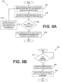
- FIGS. 9A and 9B shown are flowcharts that provide examples of the functionality of various portions of the tire mismatch system 129 according to various embodiments. It is understood that the flowcharts of FIGS. 9A and 9B provide merely examples of the many different types of functional components that may be employed to implement the operation of the tire mismatch system 129 as described herein. As an alternative, the flowcharts of FIGS. 9A and 9B may be viewed as depicting examples of elements of methods implemented in the computing environment 103 ( FIG. 1 ) or the computing device 109 ( FIG. 1 ) according to one or more embodiments.
- the tire mismatch system 129 obtains temperature values for first and second tires 119 ( FIG. 1 ) mounted adjacent to each other on a dual wheel hub 120 ( FIG. 1 ) to screen the respective tires 119 for a tire radius mismatch. To obtain the temperature values for the respective tires 119, the tire sensor data records 133 ( FIG. 1 ) are accessed.
- the tire mismatch system 129 may use one of several approaches. That is to say that in order to determine a tire radius mismatch between the tires 119, the temperature values that reflect heat generated during a free rotation of the tires 119 or a driven rotation of the tires 119 are determined or identified. This is done to avoid temperature values from the tires 119 that may be skewed by heat generated by factors external to a free rotation or driven rotation of the tires 119 as described above.
- a segment of travel is identified in which heat generated by factors external to the free rotation or driven rotation of the tires 119 is minimized.
- a segment of travel may comprise, for example, travel along a level and straight stretch of highway where the velocity of the vehicle 113 ( FIG. 1 ) is relatively constant with minimal use of brakes as determined from data obtained from the CAN bus 121 ( FIG. 1 ).
- Such a segment of travel might be one where cruise control is engaged for a period of time. If there is significant heat generated in one of the tires 119 during such a segment of travel as evidenced by the temperature values of one tire 119 relative to the other tire 119, then it is more likely due to a tire radius mismatch.
- the temperature values from the first and second tires 119 maybe processed or normalized by minimizing or eliminating the effect on temperature in the tires 119 due to factors external to the free rotation or driven rotation of the tires 119.
- the brakes may be engaged thereby generating heat in the dual wheel hub 120 and imparting an increase in temperature to the tires 119, where the tire 119 that is closest to the brake is likely to experience a greater increase in temperature than a tire 119 located farthest from the brake.
- the temperature values taken during such short segment of travel in which the brakes were engaged may be adjusted to eliminate any increase in temperature due to heat generated by the brakes.
- the temperature values from the tires 119 taken over time can be examined to determine the effect of the brakes on the temperature values and the temperature values may be adjusted accordingly.
- the temperature values may be adjusted or otherwise processed to eliminate or minimize the effect on temperature created by factors external to the free rotation or driven rotation of the tires 119 on a dual wheel hub 120.
- the temperature values may be normalized so as to represent the temperature of the tires 119 without undue influence of such external factors so that the temperature values can be used as a reliable indicator of whether a tire radius mismatch exists due to a temperature differential between the tires 119. In such case, the temperature differential would be likely due to a tire radius mismatch and not due to external factors as described herein.
- the process proceeds to box 226 to generate average temperature values for each tire 119 on the dual wheel hub 120.
- the function in box 226 may be optional where select temperature values may also be used directly without averaging.
- a temperature difference that may exist between the respective tires 119 mounted on a dual wheel hub 120 is greater or equal to a predefined temperature difference threshold. If a temperature difference between the temperature values of the respective tires 119 is greater than or equal to the predefined temperature difference threshold, then it can be assumed that such temperature difference is indicative of a tire radius mismatch that should be addressed.
- the temperature difference may be determined from average temperature values or by selected ones of the temperature values from the respective tires 119 as mentioned above.
- the predefined temperature difference threshold itself is specified so as to provide a reliable indication that a tire radius mismatch exists that should be addressed.
- the actual value of the predefined temperature difference threshold may be determined, for example, by taking actual measurements of temperature values from tires 119 in controlled settings in which a known tire mismatch exists and specifying a predefined temperature difference threshold based on the temperature differentials experienced.
- the process proceeds to box 233 in which an indication that a tire radius mismatch exists between the respective tires 119 mounted on the dual wheel hub 120.
- the indication may be stored in association with the respective tires 119 mounted on the dual wheel hub 120 for a given trailer or tractor as can be appreciated.
- the indication of a tire mismatch may be stored relative to identifiers used to maintain data for individual tractors/trailers as can be appreciated. Thereafter, the process ends.
- the process proceeds to box 236 to identify the next pair of tires 119 mounted on a dual wheel hub 120 for consideration.
- the process then reverts back to box 223 to perform the evaluation of the next pair of tires 119 for a tire radius mismatch.
- the process can be applied repeatedly to all pairs of tires 119 mounted on dual wheel hubs 120 in the fleet over time to detect tire radius mismatches in the fleet so that corrective action can be taken as necessary to eliminate the tire radius mismatches.
- the fuel consumption is improved among the vehicles 113 that use the fleet of tires 119 and the tires 119 themselves are not subjected to undue wear.
- the process determines in box 243 whether a user interface 149 ( FIG. 1 ) has been requested from a client device 111 ( FIG. 1 ). If so, then in box 246, a user interface is encoded for display that includes an indication of a tire radius mismatch if such mismatch exists in the fleet of tires 119 depicted. Next, in box 249 the encoded user interface is sent to the client 111 to be rendered on a display. Thereafter, the process ends as shown.
- the computing environment 103 includes one or more computing devices 253.
- Each computing device 253 includes at least one processor circuit, for example, having a processor 256 and a memory 259, both of which are coupled to a local interface 263.
- each computing device 253 may comprise, for example, at least one server computer or like device.
- the local interface 263 may comprise, for example, a data bus with an accompanying address/control bus or other bus structure as can be appreciated.
- Stored in the memory 259 are both data and several components that are executable by the processor 256.
- stored in the memory 259 and executable by the processor 256 may be the tire fleet management system 126 ( FIG. 1 ) that includes the tire mismatch system 129 ( FIG. 1 ), and potentially other applications.
- Also stored in the memory 259 may be a data store 123 and other data.
- an operating system may be stored in the memory 259 and executable by the processor 256.
- any component discussed herein is implemented in the form of software, any one of a number of programming languages may be employed such as, for example, C, C++, C#, Objective C, Java', JavaScript', Perl, PHP, Visual Basic ® , Python ® , Ruby, Flash ® , or other programming languages.
- executable means a program file that is in a form that can ultimately be run by the processor 256.
- Examples of executable programs may be, for example, a compiled program that can be translated into machine code in a format that can be loaded into a random access portion of the memory 259 and run by the processor 256, source code that may be expressed in proper format such as object code that is capable of being loaded into a random access portion of the memory 259 and executed by the processor 256, or source code that may be interpreted by another executable program to generate instructions in a random access portion of the memory 259 to be executed by the processor 256, etc.
- An executable program may be stored in any portion or component of the memory 259 including, for example, random access memory (RAM), read-only memory (ROM), hard drive, solid-state drive, USB flash drive, memory card, optical disc such as compact disc (CD) or digital versatile disc (DVD), floppy disk, magnetic tape, or other memory components.
- RAM random access memory
- ROM read-only memory
- hard drive solid-state drive
- USB flash drive USB flash drive
- memory card such as compact disc (CD) or digital versatile disc (DVD), floppy disk, magnetic tape, or other memory components.
- CD compact disc
- DVD digital versatile disc
- Each of the memories 259 is defined herein as including both volatile and nonvolatile memory and data storage components. Volatile components are those that do not retain data values upon loss of power. Nonvolatile components are those that retain data upon a loss of power.
- each memory 259 may comprise, for example, random access memory (RAM), read-only memory (ROM), hard disk drives, solid-state drives, USB flash drives, memory cards accessed via a memory card reader, floppy disks accessed via an associated floppy disk drive, optical discs accessed via an optical disc drive, magnetic tapes accessed via an appropriate tape drive, and/or other memory components, or a combination of any two or more of these memory components.
- the RAM may comprise, for example, static random access memory (SRAM), dynamic random access memory (DRAM), or magnetic random access memory (MRAM) and other such devices.
- the ROM may comprise, for example, a programmable read-only memory (PROM), an erasable programmable read-only memory (EPROM), an electrically erasable programmable read-only memory (EEPROM), or other like memory device.
- the processor 256 may represent multiple processors 256 and/or multiple processor cores and the memory 259 may represent multiple memories 259 that operate in parallel processing circuits, respectively.
- the local interface 263 may be an appropriate network that facilitates communication between any two of the multiple processors 256, between any processor 256 and any of the memories 259, or between any two of the memories 259, etc.
- the local interface 263 may comprise additional systems designed to coordinate this communication, including, for example, performing load balancing.
- the processor 256 may be of electrical or of some other available construction.
- tire fleet management system 126 that includes the tire mismatch system 129 and other various systems described herein may be embodied in software or code executed by general purpose hardware as discussed above, as an alternative the same may also be embodied in dedicated hardware or a combination of software/general purpose hardware and dedicated hardware. If embodied in dedicated hardware, each can be implemented as a circuit or state machine that employs any one of or a combination of a number of technologies. These technologies may include, but are not limited to, discrete logic circuits having logic gates for implementing various logic functions upon an application of one or more data signals, application specific integrated circuits (ASICs) having appropriate logic gates, field-programmable gate arrays (FPGAs), or other components, etc. Such technologies are generally well known by those skilled in the art and, consequently, are not described in detail herein.
- each block may represent a module, segment, or portion of code that comprises program instructions to implement the specified logical function(s).
- the program instructions may be embodied in the form of source code that comprises human-readable statements written in a programming language or machine code that comprises numerical instructions recognizable by a suitable execution system such as a processor 256 in a computer system or other system.
- the machine code may be converted from the source code, etc.
- each block may represent a circuit or a number of interconnected circuits to implement the specified logical function(s).
- FIGS. 8 , 9A, and 9B show a specific order of execution, it is understood that the order of execution may differ from that which is depicted. For example, the order of execution of two or more blocks may be scrambled relative to the order shown. Also, two or more blocks shown in succession in FIGS. 8 , 9A, and 9B may be executed concurrently or with partial concurrence. Further, in some embodiments, one or more of the blocks shown in FIGS. 8 , 9A, and 9B may be skipped or omitted. In addition, any number of counters, state variables, warning semaphores, or messages might be added to the logical flow described herein, for purposes of enhanced utility, accounting, performance measurement, or providing troubleshooting aids, etc. It is understood that all such variations are within the scope of the present disclosure.
- any logic or application described herein, including the tire fleet management system 126 that includes the tire mismatch system 129, that comprises software or code can be embodied in any non-transitory computer-readable medium for use by or in connection with an instruction execution system such as, for example, a processor 256 in a computer system or other system.
- the logic may comprise, for example, statements including instructions and declarations that can be fetched from the computer-readable medium and executed by the instruction execution system.
- a "computer-readable medium" can be any medium that can contain, store, or maintain the logic or application described herein for use by or in connection with the instruction execution system.
- the computer-readable medium can comprise any one of many physical media such as, for example, magnetic, optical, or semiconductor media. More specific examples of a suitable computer-readable medium would include, but are not limited to, magnetic tapes, magnetic floppy diskettes, magnetic hard drives, memory cards, solid-state drives, USB flash drives, or optical discs. Also, the computer-readable medium may be a random access memory (RAM) including, for example, static random access memory (SRAM) and dynamic random access memory (DRAM), or magnetic random access memory (MRAM).
- RAM random access memory
- SRAM static random access memory
- DRAM dynamic random access memory
- MRAM magnetic random access memory
- the computer-readable medium may be a read-only memory (ROM), a programmable read-only memory (PROM), an erasable programmable read-only memory (EPROM), an electrically erasable programmable read-only memory (EEPROM), or other type of memory device.
- ROM read-only memory
- PROM programmable read-only memory
- EPROM erasable programmable read-only memory
- EEPROM electrically erasable programmable read-only memory
- any logic or application described herein including the tire fleet management system 126 that further includes the tire mismatch system 129, may be implemented and structured in a variety of ways.
- one or more applications described may be implemented as modules or components of a single application.
- one or more applications described herein may be executed in shared or separate computing devices or a combination thereof.
- a plurality of the applications described herein may execute in the same computing device 253, or in multiple computing devices in the same computing environment 103.
- terms such as “application,” “service,” “system,” “engine,” “module,” and so on may be interchangeable and are not intended to be limiting.
- the computing device 109/111 includes at least one processor circuit, for example, having a processor 273 and a memory 276, both of which are coupled to a local interface 279.
- each computing device 109/111 may comprise, for example, a processor-based device or like device.
- the local interface 279 may comprise, for example, a data bus with an accompanying address/control bus or other bus structure as can be appreciated.
- Stored in the memory 276 are both data and several components that are executable by the processor 273.
- stored in the memory 276 and executable by the processor 273 may be the TPMS 136 ( FIG. 1 ), communication system 139 ( FIG. 1 ), the tire mismatch system 129 ( FIG. 1 ), and potentially other applications.
- the tire sensor data records 133 are stored in the memory 276.
- the fleet management interface application 143 (not shown) and potentially other applications may be stored in the memory 276 and executable by the processor 273.
- the aspects of the computing device(s) 253 set forth above also apply to the computing device 109 or 111 to the extent applicable.
Landscapes
- Engineering & Computer Science (AREA)
- Mechanical Engineering (AREA)
- Physics & Mathematics (AREA)
- General Physics & Mathematics (AREA)
- Tires In General (AREA)
- Arrangements For Transmission Of Measured Signals (AREA)
Abstract
Description
- Tires on vehicles such as tractor/trailers used to haul freight and other items may be subject to significant wear over time. Given the significant amount of weight that tires can bear on a vehicle such as a tractor/trailer and given the speeds at which such vehicles travel, excessive wear of tires is possible, which can be undesirable, such as by being detrimental to the environment.
- The invention relates to a system in accordance with claims 1 or 12 respectively, and to a method in accordance with claims 13 or 14 respectively.
- Dependent claims refer to preferred embodiments of the invention.
- Many aspects of the present disclosure can be better understood with reference to the following drawings. The components in the drawings are not necessarily to scale, with emphasis instead being placed upon clearly illustrating the principles of the disclosure. Moreover, in the drawings, like reference numerals designate corresponding parts throughout the several views.
-
FIG. 1 is a drawing of a vehicle with one or more tires that include a tread wear sensor plug according to various embodiments of the present disclosure. -
FIG. 2 is a view of a pair of tires shown inFIG. 1 mounted on a dual wheel hub according to various embodiments of the present disclosure. -
FIG. 3 is a side view of a tire shown inFIG. 1 according to various embodiments of the present disclosure. -
FIGS. 4A and 4B show a result of a finite element analysis of tires on a dual wheel hub as depicted inFIG. 2 according to various embodiments of the present disclosure. -
FIGS. 5A and 5B show a result of a finite element analysis of tires on a dual wheel hub as depicted inFIG. 2 according to various embodiments of the present disclosure. -
FIG. 6 shows a graph that depicts an indication of temperature in the tires ofFIG. 2 relative to time according to various embodiments of the present disclosure. -
FIG. 7 shows a cross-sectional view of a pair of tires as depicted inFIG. 2 that indicates a heat distribution of the tires according to various embodiments of the present disclosure. -
FIG. 8 is a flowchart that depicts a portion of the functionality of a tire mismatch system ofFIG. 1 according to various embodiments of the present disclosure. -
FIGS. 9A and 9B depict flowcharts of further portions of the functionality of the tire mismatch system ofFIG. 1 according to various embodiments of the present disclosure. -
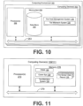
FIG. 10 shows an example of the computing environment ofFIG. 1 according to various embodiments of the present disclosure. -
FIG. 11 shows an example of computing devices depicted inFIG. 1 according to various embodiments of the present disclosure. - "CAN bus" is an abbreviation for controller area network.
- "Carcass" means the tire structure apart from the belt structure, tread, undertread, and sidewall rubber over the plies, but including the beads.
- "Footprint" means the contact patch or area of contact created by the tire tread with a flat surface, such as the ground, as the tire rotates or rolls.
- "Radial" and "radially" mean lines or directions that are perpendicular to the axis of rotation of the tire.
- "TPMS" means a tire pressure monitoring system, which is an electronic system that measures the internal pressure of a tire and is capable of communicating the pressure to a processor that is mounted on the vehicle and/or is in electronic communication with electronic systems of the vehicle.
- Various embodiments are set forth for determining whether a tire radius mismatch exists between two tires mounted on a dual wheel hub. In this respect, data is obtained from sensors in the tires that indicates the tire temperature, tire pressure, and potentially other parameters. Data may also be obtained from other systems in a vehicle from a CAN bus. According to various embodiments, a determination may be made from the data as to whether a tire radius mismatch exists between the tires mounted on the dual wheel hub. Such a tire radius mismatch can result in undue wear on the tires. Identification of such a tire radius mismatch allows for corrective action to be taken such as tire replacement or other action. In the description that follows, first various elements are introduced followed by a discussion of the operation of the same.
- With reference to
FIG. 1 , shown is an example of anetworked environment 100. Thenetworked environment 100 includes acomputing environment 103 and anetwork 106. Thecomputing environment 103 is in data communication withcomputing devices 109 that are mounted, for example, on avehicle 113 by way of thenetwork 106. The networkedenvironment 100 further includes aclient device 111 that comprises a computing device as will be described. - The vehicle includes a plurality of
sensors 116, eachsensor 116 being positioned on the inside of a respective one of a plurality oftires 119 of thevehicle 113. Thesensors 116 are employed as part of a tire pressure monitoring system (TPMS) as will be described. Some of thetires 119 are mounted ondual wheel hubs 120 such as in the case where thevehicle 113 comprises an eighteen-wheel tractor-trailer as depicted inFIG. 1 . Thevehicle 113 also includes, for example, aCAN bus 121 that facilitates data communication between various systems on thevehicle 113. In one embodiment, the computing device(s) are coupled to theCAN bus 121 and can communicate with systems included on theCAN bus 121. - Each of the major components of the
networked environment 100 is described below followed by a discussion of the operation of the same. - The
computing environment 103 may comprise, for example, a server computer or any other system providing computing capability. Alternatively, thecomputing environment 103 may employ a plurality of computing devices that may be arranged, for example, in one or more server banks or computer banks or other arrangements. Such computing devices may be located in a single installation or may be distributed among many different geographical locations. For example, thecomputing environment 103 may include a plurality of computing devices that together may comprise a hosted computing resource, a grid computing resource and/or any other distributed computing arrangement. In some cases, thecomputing environment 103 may correspond to an elastic computing resource where the allotted capacity of processing, network, storage, or other computing-related resources may vary over time. - Various applications and/or other functionality may be executed in the
computing environment 103 according to various embodiments. Also, various data is stored in adata store 123 that is accessible to thecomputing environment 103. Thedata store 123 may be representative of a plurality ofdata stores 123 as can be appreciated. The data stored in thedata store 123, for example, is associated with the operation of the various applications and/or functional entities described below. - The components executed on the
computing environment 103, for example, include a tirefleet management system 126, and other applications, services, processes, systems, engines, or functionality not discussed in detail herein. The tirefleet management system 126 is employed to track the location and status of fleet oftires 119 mounted on a plurality ofvehicles 113. Such a tirefleet management system 126 may track hundreds if not thousands oftires 119 onmany vehicles 113. The tirefleet management system 126 indicates to operators whentires 119 may need to be serviced, replaced, or the tirefleet management system 126 may provide other information. - In one embodiment, the various components of the tire
fleet management system 126 comprise atire mismatch system 129. Thetire mismatch system 129 is executed to detect whether a tire diameter mismatch exists between two tires that are mounted adjacent to each other on adual wheel hub 120 as will be described in further detail below. - In addition, stored in the
data store 123 is data in the form of tiresensor data records 133. The tiresensor data records 133 may also be stored in a memory of thecomputer device 109. Each of the tiresensor data records 133 includes an instance of a given reading of sensor data from a respective one of thetires 119 and potentially information from aCAN bus 121 on thevehicle 113 at a given time as will be described. The information from theCAN bus 121 on thevehicle 113 may comprise, for example, times when the brakes of thevehicle 113 have been engaged, torque generated by the engine and applied to wheels/tires, state of the steering wheel or whether thevehicle 113 is turning or is being driven straight, and many other information about the operation of thevehicle 113. The information from theCAN bus 121 may be communicated to the tirefleet management system 126 for use in evaluating the status of thetires 119 in the fleet. As an additional alternative, thecomputing devices 109 may obtain information from theCAN bus 121 and include such information in the tire sensor data records 133. - The
network 106 may comprise, for example, the Internet, intranets, extranets, wide area networks (WANs), local area networks (LANs), wired networks, wireless networks, cellular networks, satellite networks, cable networks, Wifi networks, or other suitable networks, etc., or any combination of two or more such networks. - The
computing device 109 comprises a processor circuit that executes, for example, a tire pressure monitoring system (TPMS) 136. In one embodiment, thecomputing device 109 may be integrated with other systems in thevehicle 113. In the case that the vehicle comprises a tractor-trailer, thecomputing device 109 may be located on the back of the trailer so as to be within range of wireless communication with thesensors 116 in thetires 119 of the trailer. Thecomputing device 109 also includes acommunication system 139 to facilitate communication with the tirefleet management system 126 over the network. In this respect, thecomputing device 109 may include appropriate communications capabilities to link to a cellular network, Wifi network, or other network communications capabilities. - In one embodiment, the
TPMS 136 communicates with thesensors 116 periodically to obtain information from thesensors 116, where such information includes a sensor identifier, pressure values, temperature values, and potentially other information from thesensors 116. Such information is stored, for example, as tiresensor data records 133 in a memory associated with thecomputing device 109. In one embodiment, each tiresensor data record 133 includes information obtained from a single readout of a givensensor 116. In addition, theTPMS 136 includes a timestamp in each tiresensor data record 133 to indicate when the pressure and temperature values were read from arespective sensor 116. Alternatively, thesensors 116 may generate a timestamp at the time it provides the sensor data to theTPMS 136. - In one embodiment,
tire mismatch system 129 may be implemented locally on thecomputing device 109 where the detection of whether a tire diameter mismatch exists between two tires that are mounted adjacent to each other on adual wheel hub 120 is performed local to thevehicle 113. - The
client device 111 may be configured to execute various applications such as a fleet management interface application 143. The fleet management interface application 143 may be executed in theclient device 111, for example, to access network content served up by the tirefleet management system 126 and/or other servers, thereby rendering auser interface 146 on a display device. In one embodiment, the tirefleet management system 126 includes a web server, although other server technologies may be employed. To this end, the fleet management interface application 143 may comprise, for example, a browser or a dedicated application, and theuser interface 146 may comprise a network page such as a web page or an application screen. Theclient device 111 may be configured to execute applications beyond the fleet management interface application 143 such as, for example, email applications, word processors, spreadsheets, and/or other applications. - The fleet management interface application 143 facilitates interaction with the tire
fleet management system 126. In one embodiment, the tirefleet management system 126 encodes theuser interface 146 that is sent to the fleet management interface application 143 and is rendered on a display device as can be appreciated. In one embodiment, theuser interface 146 includes anindication 149 that a tire radius mismatch exists between the first andsecond tires 119 when the tire radius difference of the first and second tires is detected as will be described. - The operation of the various elements of the
networked environment 100 are described with reference to the figures that follow. - Referring next to
FIG. 2 , shown is an example of a dualwheel hub assembly 153 that includes a first andsecond tire 119 mounted on adual wheel hub 120. As such, the first andsecond tires 119 are positioned adjacent to each other. Each tire includes asensor 116 that can provide measurements of pressure, temperature, and other characteristics of the tire as part of a TPMS system as can be appreciated. Also, the dualwheel hub assembly 153 includes abrake 156 as can be appreciated. - With reference to
FIG. 3 , shown is side view of atire 119 as mounted on adual wheel hub 120. Given that the footprint of thetire 119 is the contact patch or area of contact by thetire 119 with a flat surface such as the ground, a portion of thetire 119 is deflected. A radius of the tire at the shortest distance from the axis of rotation of thetire 119 and the point of greatest deflection of the footprint is a deflected radius DR of the tire. A radius R of thetire 119 is specified as the distance from the axis of rotation to an outer edge of thetire 119 outside of the footprint. The radius R can differ from onetire 119 to thenext tire 119 due to tread wear. That is to say, atire 119 that has a greater amount of tread wear will have a smaller radius R than anewer tire 119 with little or no wear. - Referring next to
FIGS. 4A and 4B , shown are finiteelement analysis renderings thermal footprints 163a-d of two different pairs of tires 119 (FIG. 1 ) that would be mounted on a dual wheel hub 120 (FIG. 2 ). Each of thethermal footprints 163a-d show a temperature distribution of the portion of atire 119 that forms a footprint of a giventire 119. When thetires 119 are placed under a load, the deflected radius DR will be the same for bothtires 119 regardless of the radius R of eachtire 119 as equilibrium is reached between the load,tires 119, and other elements. For both of finiteelement analysis renderings 160a/b, the load on the pair oftires 119 is 11,350 foot-pounds (5675 foot-pounds x 2) at 100 PSI moving at 50 mph. - Referring first to
FIG. 4A , the theoreticalthermal footprints tires 119 that are both new, where each of thetires 119 in the pair has the same radius R. - As shown in the theoretical
thermal footprint 163a, the deflected radius DR is 474.8 mm for both of thetires 119 that theoretically exist on a givendual wheel hub 120. As shown, the temperature distribution of each of thethermal footprints tires 119 have the same radius R. - With reference to
FIG. 4B , the theoreticalthermal footprints tires 119 that are mismatched in that the respective radius R of each of thetires 119 is different. In particular, thetire 119 corresponding to thethermal footprint 163c is new with a maximum radius R and thetire 119 corresponding to thethermal footprint 163d is worn such that the tread depth is 6/32 inches (4.76 mm; 1 inch = 25.4 mm). A new tire would have a tread depth that may be, for example, 18/32 inches (1 inch = 25.4 mm). As shown, thethermal footprint 163c is much larger than thethermal footprint 163d due to the fact that thetire 119 corresponding to thethermal footprint 163c has a larger radius R than thetire 119 corresponding to thethermal footprint 163d. Also, as shown, thetire 119 corresponding to thethermal footprint 163c has more areas that reach higher temperatures. This is likely due to the fact that thethermal footprint 163c is larger and that thecorresponding tire 119 bears more weight than thetire 119 corresponding to thethermal footprint 163d. This fact likely results in a higher rate of wear ofsuch tire 119, thereby resulting in a shorter useful life of thetire 119 until the tread has worn to maximum recommended limits. - In addition, the wear pattern associated with the
thermal footprint 163d is much different, resulting in further wear of the tread of thecorresponding tire 119 that may be uneven. Given that the radius R of therespective tires 119 are different for thethermal footprints 163c/d, then the wear of therespective tires 119 differs relative to thetires 119 corresponding to thethermal footprints 163a/b ofFIG. 4A . - With reference to
FIGS. 5A and 5B , shown are finiteelement analysis renderings thermal footprints 169a-d of two different pairs of tires 119 (FIG. 1 ) that would be mounted on a dual wheel hub 120 (FIG. 2 ). Each of thethermal footprints 169a-d show a temperature distribution of the portion of atire 119 that forms a footprint of a giventire 119 as depicted inFIGS. 4A and 4B . When thetires 119 are placed under a load, the deflected radius DR will be the same for bothtires 119 regardless of the radius R of eachtire 119 as equilibrium is reached between the load,tires 119, and other elements. For both of finiteelement analysis renderings 166a/b, the load on the pair oftires 119 is 11,350 foot-pounds (5675 foot-pounds x 2) at 100 PSI moving at 50 mph. The deflected radius DR for thethermal footprints 169a/b is 475.66 mm. The deflected radius DR for thethermal footprints 169c/d is 470.63 mm. - With reference to
FIGS. 4A, 4B ,5A, and 5B , the finiteelement analysis renderings 160a/b and 166a/b show that in situations where there is a mismatch in the radius R of twotires 119 installed on adual wheel hub 120, more heat is generated in thetire 119 having the greatest radius R of the twotires 119. - Referring next to
FIG. 6 , shown are curves that depict the loads that are born by the individual tires 119 (FIG. 1 ) on a dual wheel hub 120 (FIG. 2 ). - With reference to
FIG. 7 , shown are temperature profiles of twotires 119, denoted herein astires tire 119a has a tread depth of 18/32 inches (1 inch = 25.4 mm) and thetire 119b has a tread depth of 6/32 inches. Thus, thetire 119a has a radius R that is greater than the radius R of thetire 119b. Also, thetire 119a bears approximately 6638 foot-pounds at 100 PSI and thetire 119b bears approximately 4633 foot-pounds at 100 PSI. Given its greater size and the fact that it bears a greater amount of weight, the material of thetire 119a runs at higher temperatures. Specifically, the areas where belts and other such structures are included in thetire 119a are subject to greater frictional forces and experience higher temperatures than do the counterpart structures in thetire 119b. As a consequence, the resulting temperature of the cavity of thetire 119a is 72.7 degrees Celsius and the temperature of the cavity of thetire 119b is 53.7 degrees Celsius. This is a further illustration of the fact that afirst tire 119 mounted on a dual wheel hub 120 (FIG. 2 ) having a greater radius R than asecond tire 119 mounted on the samedual wheel hub 120 will be heated to higher temperatures than thesecond tire 119 having a lesser radius R. - Referring back to
FIG. 1 , the operation of the various elements of thenetworked environment 100 is discussed. As thevehicle 113 is driven, thesensors 116 generate readings of temperature, pressure, and potentially other parameters associated with a respective one of thetires 119. TheTPMS 136 executed in acomputing device 109 communicates with thesensors 116 to obtain the pressure, temperature, and other readings from therespective sensors 116. In one embodiment, thesensors 116 generate the full tiresensor data record 133 including sensor identifier information, a timestamp, pressure, temperature, and potentially other parameters. Thesensors 116 transmit the same to theTPMS 136 executed by thecomputing device 109. Alternatively, thesensors 116 may transmit sensor identifier information, pressure information, temperature information, and potentially other parameters to theTPMS 136 in thecomputing device 109, and thecomputing device 109 may package such information in the form of a tiresensor data record 133 with a timestamp. - In one embodiment, the tire
sensor data records 133 are temporarily stored in thecomputing device 109. Thecommunication system 139 periodically transmits the tiresensor data records 133 to the tirefleet management system 126 where they are stored in thedata store 123. Alternatively, in cases where thetire mismatch system 129 is executed in thecomputing device 109, the tiresensor data records 133 may remain in a memory of thecomputing device 109 for purposes of analysis by thetire mismatch system 129. In such a case, a copy of the tiresensor data records 133 may still be transmitted to the tirefleet management system 126. - The tire
fleet management system 126 is executed in thecomputing environment 103 to track the status oftires 119 onmultiple vehicles 113. In one embodiment, thetire mismatch system 129 is executed as part of the tirefleet management system 126 to detect when there is a tire radius difference between first andsecond tires 119 positioned adjacent to each other on adual wheel hub 120. Such a tire radius difference is identified so that corrective action may be taken to prevent accelerated wear of the tread of thetires 119 by tire replacement or other action. - In one embodiment, the status of
tires 119 is maintained on the tirefleet management system 126. From time to time, the fleet management interface application 143 may request auser interface 146 to review the status of thetires 119 in the fleet, where theuser interface 146 indicates when a tire radius mismatch is detected. To this end, the tirefleet management system 126 encodes for display an indication that a tire radius mismatch exists between the first andsecond tires 119 on a givendual wheel hub 120 of arespective vehicle 113 when it has been detected that the tire radius difference exists. The indication may be encoded, for example, as part of a network page such as a web page or some other graphical user interface. The network page or other interface that embodies the indication is transmitted to theclient device 111 and rendered on a display device as theuser interface 149. - The indication may be any interface mechanism that shows that the tire radius mismatch exists between the respective two
tires 119 for a givenvehicle 113. For example,mismatched tires 119 may be represented by user interface components that involve blinking, highlighting with a predefined color, or other indication. - In order to determine whether a tire radius difference exists between first and
second tires 119 mounted on adual wheel hub 120, thetire mismatch system 129 accesses temperature values or other values from the tire sensor data records 133. In one embodiment, the existence of a tire radius difference is determined based on the temperature values from the tiresensor data records 133 from the respective first andsecond tires 119 on thedual wheel hub 120. The temperature values from therespective tires 119 may be used themselves or, alternatively, an average temperature value may be calculated for eachtire 119 on thedual wheel hub 120 from multiple temperature values taken over time, over a given segment of travel, or on some other basis. - In order to determine whether the tire radius difference exists based on the temperature values from each
tire 119 on adual wheel hub 120, a temperature difference threshold may be specified. This reflects the fact that when a sufficient tire radius difference exists between first and second tires, a temperature differential is created between the twotires 119 given that thetire 119 having the greater radius R is subject to greater frictional forces than thetire 119 having the lesser radius R on thedual wheel hub 120 as described above. - According to one embodiment, a tire radius difference is detected when a difference in the temperature values from the
respective tires 119 on adual wheel hub 120 is greater than or equal to the predefined temperature difference threshold. Such temperature values may be individual temperature values or averaged temperature values over time. - In addition, care is taken to ensure that the temperature values from the tire
sensor data records 133 are not unduly influenced by factors external to a free rotation or a driven rotation of the first andsecond tires 119 on adual wheel hub 120. A free rotation refers totires 119 on adual wheel hub 120 that is located, for example, on a trailer of a tractor/trailer wheresuch tires 119 rotate freely with the movement of the trailer. A driven rotation refers totires 119 on adual wheel hub 120 that is located on a tractor of a tractor/trailer that are subject to torque from the motor and transmission of the tractor/trailer. As such, thetires 119 that rotate freely are potentially subject to less friction thantires 119 that are driven by the engine of thevehicle 113. - Factors external to a free rotation or a driven rotation of the
tires 119 may be, for example, an application of the brakes of thevehicle 113. As shown with reference toFIG. 2 , abrake 156 is typically located adjacent to thedual wheel hub 120. When thebrake 156 is engaged, heat is generated that may be conducted through thedual wheel hub 120 to thetires 119. Given that thebrake 156 is typically closer to an interiormounted tire 119, the interior mountedtire 119 on adual wheel hub 120 may experience higher temperatures than the exterior mountedtire 119. Alternatively, an item such as a mud flap may be positioned incorrectly resulting in unwanted friction between the item and one or both of thetires 119 mounted on thedual wheel hub 120, thereby generating heat. Still further, bearings associated with thedual wheel hub 120 may be faulty resulting in friction and the generation of heat. There may be other factors that would influence the temperatures sensed in thetires 119 of adual wheel hub 120. - According to one embodiment, the
tire mismatch system 129 identifies temperature values from the tires in which an amount of heat generated due to factors external to a free rotation or a driven rotation of the first andsecond tires 119 on adual wheel hub 120 is minimized. This may be done, for example, by identifying a segment of travel for thetires 119 in which an amount of heat generated by such external factors are eliminated or minimized, where the temperature values were generated while the first andsecond tires 119 were in transit in the segment of travel. Such a segment of travel may be, for example, a segment of travel of thevehicle 113 in which the brakes were never employed and thevehicle 113 traveled at a relatively constant velocity with little acceleration or deceleration such as might occur on a relatively level and straight portion of highway. - A tire radius difference between the
respective tires 119 on adual wheel hub 120 may be detected or determined to exist if a difference between the temperature values of therespective tires 119 at a given time on adual wheel hub 120 are greater than or equal to a predefined temperature difference threshold. - Alternatively, a first average of temperature value may be calculated from temperature values from a
first tire 119 on adual wheel hub 120 taken during the travel segment, and a second average of temperature values may be calculated from temperature values from asecond tire 119 on thedual wheel hub 120 taken during the same travel segment. A tire radius difference between therespective tires 119 on adual wheel hub 120 may be detected or determined to exist if a difference between first and second average of temperature values are greater than or equal to a predefined temperature difference threshold. - As an additional alternative, the temperature values from the first and
second tires 119 ondual wheel hub 120 may be processed to minimize or remove the effect of factors external to a free rotation or a driven rotation of the first and second tires. In so processing, for example, temperature values that are temporarily elevated due to an application of the brakes or other external factor may be lowered accordingly based on temperature values that are not subject to the influence of the brakes or other short-term source of friction and heat. The determination of whether a tire radius difference exists may be made using the processed temperature values from the first andsecond tires 119 on thedual wheel hub 120. In particular, a difference in the processed temperature values from the first andsecond tires 119 may be compared with the predefined temperature difference threshold as described above. Alternatively, first and second average temperature values may be calculated from the processed temperature values taken from therespective tires 119. A difference between the first and second average temperature values may be compared with the predefined temperature difference threshold as described above. - In another embodiment the predefined temperature difference threshold is determined relative to baseline temperature values determined for first and
second tires 119 on adual wheel hub 120. That is to say, in determining a difference between the temperature values from first andsecond tires 119 on adual wheel hub 120, the baseline temperature values may be taken into account. For example, the predefined temperature difference threshold may be determined relative to a baseline temperature differential calculated from the respective baseline temperature values for each of thetires 119. This reflects that there may be process variation from onetire 119 to the next, which may result in variation between respective baseline temperature values. Also, the position of the respective tires on a givenvehicle 113 may result in variation of baseline temperature values oftires 119 where some may be more exposed to air movement and other factors. - To generate baseline temperature values, in one embodiment, the
tire mismatch system 129 identifies a time period in which a difference between a first radius of a first tire and a second radius of a second tire is known to be less than a maximum allowable radius difference threshold. That is to say, a time period is identified in which therespective tires 119 on adual wheel hub 120 are known to be roughly the same size or where a difference between the tire radii R for therespective tires 119 is within the maximum allowable radius difference threshold with respect to each other. In one embodiment, the maximum allowable radius difference threshold is specified as 6.35 mm or ¼ inch, although other differences may be specified. - In order to determine a time period where a difference in the tire radii R of the
tires 119 on adual wheel hub 120 is within the maximum allowable radius difference threshold, records may be consulted that indicate when twonew tires 119 having the same tire radius R have been installed on a givendual wheel hub 120. In this respect, one may employ theclient device 111 to input a time whensuch tires 119 were installed on a givenvehicle 113 by way of anappropriate user interface 146. Alternatively, thetires 119 on adual wheel hub 120 may be measured from time to time and the tire radius R for eachtire 119 may be input into thetire mismatch system 129 by way of auser interface 149, where a time of the measurement may be provided when such inputs are made. When the tire radius R of eachtire 119 is input, thetire mismatch system 129 can determine whether the difference in the tire radii R of thetires 119 on adual wheel hub 120 is within the maximum allowable radius difference threshold. - Once a time period is identified where the difference in the tire radii R of the
tires 119 on adual wheel hub 120 is known to be within the maximum allowable radius difference threshold, then a segment of travel of the tires is identified that occurs within the time period, where the amount of heat generated in therespective tires 119 mounted on thedual wheel hub 120 due to a factor external to a free rotation or a driven rotation of the first andsecond tires 119 is substantially minimized. A first baseline temperature value for a first one of thetires 119 is determined based on a plurality of first temperature values taken from thefirst tire 119 during the segment of travel. Also, a second baseline temperature value for a second one of thetires 119 is determined based on a plurality of second temperature values taken from thesecond tire 119 during the segment of travel. - Referring next to
FIG. 8 , shown is a flowchart that provides one example of the operation of a portion of thetire mismatch system 129 according to various embodiments. It is understood that the flowchart ofFIG. 8 provides merely an example of the many different types of functional arrangements that may be employed to implement the operation of the portion of thetire mismatch system 129 as described herein. As an alternative, the flowchart ofFIG. 8 may be viewed as depicting an example of elements of a method implemented in the computing environment 103 (FIG. 1 ) or the computing device 109 (FIG. 1 ) according to one or more embodiments. - Beginning with box 203, the
tire mismatch system 129 identifies a time period where a difference between the tire radii R of the two tires 119 (FIG. 1 ) on a dual wheel hub 120 (FIG. 1 ) is known to be within the maximum allowable radius difference threshold. This may be determined by identifying times stored in the data store, for example, where it is known that the tire radii R of the two tires is known to be within the maximum allowable radius difference threshold. Such times may be input into thetire mismatch system 129 whensuch tires 119 are initially installed or measured from time to time by way of appropriate user interfaces 146 (FIG. 1 ) as was discussed above. - The time period is a length of time in which it is assumed that the tire radius R of each
tire 119 mounted on adual wheel hub 120 will not significantly change such that it can be assumed that any difference that arises between the tire radii R of the twotires 119 will remain within the maximum allowable radius difference threshold. Alternatively, rather than a time period, a distance of travel may be specified of thetires 119 after the time where it is known that the radii R of the twotires 119 will remain within the maximum allowable radius difference threshold. - Thereafter, in
box 206, a segment of travel is identified during the time period or distance of travel identified in box 203 above from the tire sensor data records 133 (FIG. 1 ) in which heat generated due to factors external to the free rotation or driven rotation of thetires 119 is minimized. This ensures that any temperature differential that exists between therespective tires 119 mounted on adual wheel hub 120 is not due to such external factors. The external factors may include an application of the brakes of the vehicle, friction due to mud flaps, friction due to faulty bearings, or other external factors. As such, the tiresensor data records 133 and/or other data may be consulted to identify segments of travel where such external factors are minimized or do not occur. For example, a given segment of travel might be identified where the brakes of the vehicle were not engaged. - Next, in
box 209 an average baseline temperature value is calculated for each of thetires 119 mounted on adual wheel hub 120 from the temperature values in the tiresensor data records 133 taken for thetires 119 while in transit through the segment of travel. - In
box 213, the average baseline temperature values are stored in the data store 123 (FIG. 1 ) in association with therespective tires 119 to be consulted to detect when a tire radius difference exists such that corrective action should be taken. Thereafter, this portion of thetire mismatch system 129 ends as shown. - Referring next to
FIGS. 9A and 9B , shown are flowcharts that provide examples of the functionality of various portions of thetire mismatch system 129 according to various embodiments. It is understood that the flowcharts ofFIGS. 9A and 9B provide merely examples of the many different types of functional components that may be employed to implement the operation of thetire mismatch system 129 as described herein. As an alternative, the flowcharts ofFIGS. 9A and 9B may be viewed as depicting examples of elements of methods implemented in the computing environment 103 (FIG. 1 ) or the computing device 109 (FIG. 1 ) according to one or more embodiments. - Beginning with
box 223, thetire mismatch system 129 obtains temperature values for first and second tires 119 (FIG. 1 ) mounted adjacent to each other on a dual wheel hub 120 (FIG. 1 ) to screen therespective tires 119 for a tire radius mismatch. To obtain the temperature values for therespective tires 119, the tire sensor data records 133 (FIG. 1 ) are accessed. - In order to ensure that the temperature values for the
tires 119 accurately reflect the temperature of therespective tires 119 during a free rotation or a driven rotation of thetires 119, thetire mismatch system 129 may use one of several approaches. That is to say that in order to determine a tire radius mismatch between thetires 119, the temperature values that reflect heat generated during a free rotation of thetires 119 or a driven rotation of thetires 119 are determined or identified. This is done to avoid temperature values from thetires 119 that may be skewed by heat generated by factors external to a free rotation or driven rotation of thetires 119 as described above. - In one approach, a segment of travel is identified in which heat generated by factors external to the free rotation or driven rotation of the
tires 119 is minimized. Such a segment of travel may comprise, for example, travel along a level and straight stretch of highway where the velocity of the vehicle 113 (FIG. 1 ) is relatively constant with minimal use of brakes as determined from data obtained from the CAN bus 121 (FIG. 1 ). Such a segment of travel might be one where cruise control is engaged for a period of time. If there is significant heat generated in one of thetires 119 during such a segment of travel as evidenced by the temperature values of onetire 119 relative to theother tire 119, then it is more likely due to a tire radius mismatch. - Alternatively, the temperature values from the first and
second tires 119 maybe processed or normalized by minimizing or eliminating the effect on temperature in thetires 119 due to factors external to the free rotation or driven rotation of thetires 119. For example, in some short segments of travel, the brakes may be engaged thereby generating heat in thedual wheel hub 120 and imparting an increase in temperature to thetires 119, where thetire 119 that is closest to the brake is likely to experience a greater increase in temperature than atire 119 located farthest from the brake. The temperature values taken during such short segment of travel in which the brakes were engaged may be adjusted to eliminate any increase in temperature due to heat generated by the brakes. To this end, the temperature values from thetires 119 taken over time can be examined to determine the effect of the brakes on the temperature values and the temperature values may be adjusted accordingly. - In this manner, the temperature values may be adjusted or otherwise processed to eliminate or minimize the effect on temperature created by factors external to the free rotation or driven rotation of the
tires 119 on adual wheel hub 120. Stated another way, the temperature values may be normalized so as to represent the temperature of thetires 119 without undue influence of such external factors so that the temperature values can be used as a reliable indicator of whether a tire radius mismatch exists due to a temperature differential between thetires 119. In such case, the temperature differential would be likely due to a tire radius mismatch and not due to external factors as described herein. - Assuming that the
tire mismatch system 129 has obtained temperature values in which the influence from factors external to a free rotation or driven rotation of thetires 119 is minimized or eliminated from a segment of travel or from processing as noted above, the process proceeds tobox 226 to generate average temperature values for eachtire 119 on thedual wheel hub 120. Note that the function inbox 226 may be optional where select temperature values may also be used directly without averaging. - Then, in
box 229 it is determined whether a temperature difference that may exist between therespective tires 119 mounted on adual wheel hub 120 is greater or equal to a predefined temperature difference threshold. If a temperature difference between the temperature values of therespective tires 119 is greater than or equal to the predefined temperature difference threshold, then it can be assumed that such temperature difference is indicative of a tire radius mismatch that should be addressed. The temperature difference may be determined from average temperature values or by selected ones of the temperature values from therespective tires 119 as mentioned above. - It should be noted that the predefined temperature difference threshold itself is specified so as to provide a reliable indication that a tire radius mismatch exists that should be addressed. The actual value of the predefined temperature difference threshold may be determined, for example, by taking actual measurements of temperature values from
tires 119 in controlled settings in which a known tire mismatch exists and specifying a predefined temperature difference threshold based on the temperature differentials experienced. - Assuming that a temperature differential exists between the
respective tires 119 on adual wheel hub 120 that is greater than the predefined temperature difference threshold, then the process proceeds tobox 233 in which an indication that a tire radius mismatch exists between therespective tires 119 mounted on thedual wheel hub 120. Note that the indication may be stored in association with therespective tires 119 mounted on thedual wheel hub 120 for a given trailer or tractor as can be appreciated. To this end, the indication of a tire mismatch may be stored relative to identifiers used to maintain data for individual tractors/trailers as can be appreciated. Thereafter, the process ends. - Assuming, however, that it is determined that a temperature differential from the
respective tires 119 on adual wheel hub 120 is less than the predefined temperature difference threshold inbox 229, then the process proceeds tobox 236 to identify the next pair oftires 119 mounted on adual wheel hub 120 for consideration. The process then reverts back tobox 223 to perform the evaluation of the next pair oftires 119 for a tire radius mismatch. In this manner, the process can be applied repeatedly to all pairs oftires 119 mounted ondual wheel hubs 120 in the fleet over time to detect tire radius mismatches in the fleet so that corrective action can be taken as necessary to eliminate the tire radius mismatches. As such, the fuel consumption is improved among thevehicles 113 that use the fleet oftires 119 and thetires 119 themselves are not subjected to undue wear. - Referring next to the portion of the
tire mismatch system 129 depicted inFIG. 9B , the process determines inbox 243 whether a user interface 149 (FIG. 1 ) has been requested from a client device 111 (FIG. 1 ). If so, then inbox 246, a user interface is encoded for display that includes an indication of a tire radius mismatch if such mismatch exists in the fleet oftires 119 depicted. Next, inbox 249 the encoded user interface is sent to theclient 111 to be rendered on a display. Thereafter, the process ends as shown. - With reference to
FIG. 10 , shown is a schematic block diagram of thecomputing environment 103 according to an embodiment of the present disclosure. Thecomputing environment 103 includes one ormore computing devices 253. Eachcomputing device 253 includes at least one processor circuit, for example, having aprocessor 256 and amemory 259, both of which are coupled to alocal interface 263. To this end, eachcomputing device 253 may comprise, for example, at least one server computer or like device. Thelocal interface 263 may comprise, for example, a data bus with an accompanying address/control bus or other bus structure as can be appreciated. - Stored in the
memory 259 are both data and several components that are executable by theprocessor 256. In particular, stored in thememory 259 and executable by theprocessor 256 may be the tire fleet management system 126 (FIG. 1 ) that includes the tire mismatch system 129 (FIG. 1 ), and potentially other applications. Also stored in thememory 259 may be adata store 123 and other data. In addition, an operating system may be stored in thememory 259 and executable by theprocessor 256. - It is understood that there may be other applications that are stored in the
memory 259 and are executable by theprocessor 256 as can be appreciated. Where any component discussed herein is implemented in the form of software, any one of a number of programming languages may be employed such as, for example, C, C++, C#, Objective C, Java', JavaScript', Perl, PHP, Visual Basic®, Python®, Ruby, Flash®, or other programming languages. - A number of software components are stored in a
memory 259 and are executable by aprocessor 256. In this respect, the term "executable" means a program file that is in a form that can ultimately be run by theprocessor 256. Examples of executable programs may be, for example, a compiled program that can be translated into machine code in a format that can be loaded into a random access portion of thememory 259 and run by theprocessor 256, source code that may be expressed in proper format such as object code that is capable of being loaded into a random access portion of thememory 259 and executed by theprocessor 256, or source code that may be interpreted by another executable program to generate instructions in a random access portion of thememory 259 to be executed by theprocessor 256, etc. An executable program may be stored in any portion or component of thememory 259 including, for example, random access memory (RAM), read-only memory (ROM), hard drive, solid-state drive, USB flash drive, memory card, optical disc such as compact disc (CD) or digital versatile disc (DVD), floppy disk, magnetic tape, or other memory components. - Each of the
memories 259 is defined herein as including both volatile and nonvolatile memory and data storage components. Volatile components are those that do not retain data values upon loss of power. Nonvolatile components are those that retain data upon a loss of power. Thus, eachmemory 259 may comprise, for example, random access memory (RAM), read-only memory (ROM), hard disk drives, solid-state drives, USB flash drives, memory cards accessed via a memory card reader, floppy disks accessed via an associated floppy disk drive, optical discs accessed via an optical disc drive, magnetic tapes accessed via an appropriate tape drive, and/or other memory components, or a combination of any two or more of these memory components. In addition, the RAM may comprise, for example, static random access memory (SRAM), dynamic random access memory (DRAM), or magnetic random access memory (MRAM) and other such devices. The ROM may comprise, for example, a programmable read-only memory (PROM), an erasable programmable read-only memory (EPROM), an electrically erasable programmable read-only memory (EEPROM), or other like memory device. - Also, for each
computing device 253, theprocessor 256 may representmultiple processors 256 and/or multiple processor cores and thememory 259 may representmultiple memories 259 that operate in parallel processing circuits, respectively. In such a case, thelocal interface 263 may be an appropriate network that facilitates communication between any two of themultiple processors 256, between anyprocessor 256 and any of thememories 259, or between any two of thememories 259, etc. Thelocal interface 263 may comprise additional systems designed to coordinate this communication, including, for example, performing load balancing. Theprocessor 256 may be of electrical or of some other available construction. - Although the tire
fleet management system 126 that includes thetire mismatch system 129 and other various systems described herein may be embodied in software or code executed by general purpose hardware as discussed above, as an alternative the same may also be embodied in dedicated hardware or a combination of software/general purpose hardware and dedicated hardware. If embodied in dedicated hardware, each can be implemented as a circuit or state machine that employs any one of or a combination of a number of technologies. These technologies may include, but are not limited to, discrete logic circuits having logic gates for implementing various logic functions upon an application of one or more data signals, application specific integrated circuits (ASICs) having appropriate logic gates, field-programmable gate arrays (FPGAs), or other components, etc. Such technologies are generally well known by those skilled in the art and, consequently, are not described in detail herein. - The flowcharts of
FIGS. 8 ,9A, and 9B show the functionality and operation of an implementation of portions of thetire mismatch system 129. If embodied in software, each block may represent a module, segment, or portion of code that comprises program instructions to implement the specified logical function(s). The program instructions may be embodied in the form of source code that comprises human-readable statements written in a programming language or machine code that comprises numerical instructions recognizable by a suitable execution system such as aprocessor 256 in a computer system or other system. The machine code may be converted from the source code, etc. If embodied in hardware, each block may represent a circuit or a number of interconnected circuits to implement the specified logical function(s). - Although the flowcharts of
FIGS. 8 ,9A, and 9B show a specific order of execution, it is understood that the order of execution may differ from that which is depicted. For example, the order of execution of two or more blocks may be scrambled relative to the order shown. Also, two or more blocks shown in succession inFIGS. 8 ,9A, and 9B may be executed concurrently or with partial concurrence. Further, in some embodiments, one or more of the blocks shown inFIGS. 8 ,9A, and 9B may be skipped or omitted. In addition, any number of counters, state variables, warning semaphores, or messages might be added to the logical flow described herein, for purposes of enhanced utility, accounting, performance measurement, or providing troubleshooting aids, etc. It is understood that all such variations are within the scope of the present disclosure. - Also, any logic or application described herein, including the tire
fleet management system 126 that includes thetire mismatch system 129, that comprises software or code can be embodied in any non-transitory computer-readable medium for use by or in connection with an instruction execution system such as, for example, aprocessor 256 in a computer system or other system. In this sense, the logic may comprise, for example, statements including instructions and declarations that can be fetched from the computer-readable medium and executed by the instruction execution system. In the context of the present disclosure, a "computer-readable medium" can be any medium that can contain, store, or maintain the logic or application described herein for use by or in connection with the instruction execution system. - The computer-readable medium can comprise any one of many physical media such as, for example, magnetic, optical, or semiconductor media. More specific examples of a suitable computer-readable medium would include, but are not limited to, magnetic tapes, magnetic floppy diskettes, magnetic hard drives, memory cards, solid-state drives, USB flash drives, or optical discs. Also, the computer-readable medium may be a random access memory (RAM) including, for example, static random access memory (SRAM) and dynamic random access memory (DRAM), or magnetic random access memory (MRAM). In addition, the computer-readable medium may be a read-only memory (ROM), a programmable read-only memory (PROM), an erasable programmable read-only memory (EPROM), an electrically erasable programmable read-only memory (EEPROM), or other type of memory device.
- Further, any logic or application described herein, including the tire
fleet management system 126 that further includes thetire mismatch system 129, may be implemented and structured in a variety of ways. For example, one or more applications described may be implemented as modules or components of a single application. Further, one or more applications described herein may be executed in shared or separate computing devices or a combination thereof. For example, a plurality of the applications described herein may execute in thesame computing device 253, or in multiple computing devices in thesame computing environment 103. Additionally, it is understood that terms such as "application," "service," "system," "engine," "module," and so on may be interchangeable and are not intended to be limiting. - With reference to
FIG. 11 , shown is a schematic block diagram that provides an illustration of thecomputer devices computing device 109/111 includes at least one processor circuit, for example, having aprocessor 273 and amemory 276, both of which are coupled to alocal interface 279. To this end, eachcomputing device 109/111 may comprise, for example, a processor-based device or like device. Thelocal interface 279 may comprise, for example, a data bus with an accompanying address/control bus or other bus structure as can be appreciated. - Stored in the
memory 276 are both data and several components that are executable by theprocessor 273. In particular, in the case of thecomputing device 109, stored in thememory 276 and executable by theprocessor 273 may be the TPMS 136 (FIG. 1 ), communication system 139 (FIG. 1 ), the tire mismatch system 129 (FIG. 1 ), and potentially other applications. Also, the tiresensor data records 133 are stored in thememory 276. In the case of thecomputing device 111, the fleet management interface application 143 (not shown) and potentially other applications may be stored in thememory 276 and executable by theprocessor 273. Generally, the aspects of the computing device(s) 253 set forth above also apply to thecomputing device
Claims (15)
- A system comprising:
at least one processor circuit with a memory comprising a plurality of instructions, wherein when executed by the processor circuit, the instructions cause the at least one processor circuit to at least:access a plurality of first temperature values of a first tire and a plurality of second temperature values of a second tire, the first tire being positioned adjacent to the second tire on a dual wheel hub;detect whether a tire radius difference exists between a first radius of the first tire and a second radius of the second tire based on the first and second temperature values; andencoding for display an indication that a tire radius mismatch exists between the first and second tires. - The system of claim 1, wherein the detection of whether the tire radius difference exists between a first radius of the first tire and a second radius of the second tire based on the first and second temperature values further comprises:identifying a segment of travel of the first and second tires in which an amount of heat generated due to a factor external to a free rotation of the first and second tires is substantially minimized, and the first and second temperature values are generated while the first and second tires are in transit in the segment of travel; anddetermining whether a difference between one of the first temperature values and one of the second temperature values is at least as great as a predefined temperature difference threshold, the predefined temperature difference threshold being preferably determined relative to a baseline temperature differential.
- The system of claim 1 or 2, wherein the detection of whether the tire radius difference exists between a first radius of the first tire and a second radius of the second tire based on the first and second temperature values further comprises:identifying a segment of travel of the first and second tires in which an amount of heat generated due to a factor external to a free rotation of the first and second tires is substantially minimized, and the first and second temperature values are generated while the first and second tires are in transit in the segment of travel; anddetermining whether a difference between an average of the first temperature values and an average of the second temperature values is at least as great as a predefined temperature difference threshold.
- The system of at least one of the previous claims, wherein the detection of whether the tire radius difference exists between a first radius of the first tire and a second radius of the second tire based on the first and second temperature values further comprises:identifying a segment of travel of the first and second tires in which an amount of heat generated due to a factor external to a driven rotation of the first and second tires is substantially minimized, and the first and second temperature values are generated while the first and second tires are in transit in the segment of travel; anddetermining whether a difference between one of the first temperature values and one of the second temperature values is at least as great as a predefined temperature difference threshold.
- The system of at least one of the previous claims, wherein the detection of whether the tire radius difference exists between a first radius of the first tire and a second radius of the second tire based on the first and second temperature values further comprises:processing the first and second temperature values to minimize an effect of a factor external to a free rotation of the first and second tires on a temperature of the first and second tires; anddetermining whether a difference between a processed one of the first temperature values and a processed one of the second temperature values is at least as great as a predefined temperature difference threshold.
- The system of at least one of the previous claims, wherein the detection of whether the tire radius difference exists between a first radius of the first tire and a second radius of the second tire based on the first and second temperature values further comprises:processing the first and second temperature values to minimize an effect of a factor external to a driven rotation of the first and second tires on a temperature of the first and second tires; anddetermining whether a difference between a processed one of the first temperature values and a processed one of the second temperature values is at least as great as a predefined temperature difference threshold.
- The system of at least one of the previous claims, wherein the first temperature values are generated by a first temperature sensor associated with the first tire, and the second temperature values are generated by a second temperature sensor associated with the second tire.
- The system of at least one of the previous claims, wherein the instructions further cause the at least one processor circuit to render the indication that the tire radius mismatch exists between the first and second tires on a display device.
- The system of at least one of the previous claims, further comprising:
a gateway device associated with the first and second tires, wherein the first and second temperature values are stored in the gateway device and wherein the instructions further cause the at least one processor circuit to communicate with the gateway device through a network to obtain the first and second temperature values. - The system of claim 9, wherein the first temperature values are generated by a first temperature sensor associated with the first tire, and the second temperature values are generated by a second temperature sensor associated with the second tire, and the gateway device is in wireless communication with the first and second temperature sensors and the gateway device obtains the first and second temperature values from the first and second temperature sensors.
- The system of at least one of the previous claims, wherein the first temperature values are generated by a first temperature sensor associated with the first tire, and the second temperature values are generated by a second temperature sensor associated with the second tire, and wherein the at least one processor circuit is included in a gateway device, the gateway device being in wireless communication with the first and second temperature sensors and the gateway device obtaining the first and second temperature values from the first and second temperature sensors.
- A system comprising:
at least one processor circuit with a memory comprising a plurality of instructions, wherein when executed by the processor circuit, the instructions cause the at least one processor circuit to at least:identify a time period in which a difference between a first radius of a first tire and a second radius of a second tire is known to be less than a maximum allowable difference threshold, the first and second tires being mounted on a dual wheel hub, preferably a dual wheel hub of a tractor;identify a segment of travel of the first and second tires occurring within the time period in which an amount of heat generated in the first and second tires due to a factor external to a free rotation of the first and second tires is substantially minimized;determine a first baseline temperature value for the first tire based on a plurality of first temperature values from the first tire, the first temperature values being generated during the segment of travel; anddetermine a second baseline temperature value for the second tire based on a plurality of second temperature values from the second tire, the second temperature values being generated during the segment of travel. - A method of detecting a tire radius mismatch, the method comprising:providing at least one processor circuit with a memory comprising a plurality of instructions;executing the instructions by the processor circuit, the instructions causing the at least one processor circuit to at least:access a plurality of first temperature values of a first tire and a plurality of second temperature values of a second tire, the first tire being positioned adjacent to the second tire on a dual wheel hub;detect whether a tire radius difference exists between a first radius of the first tire and a second radius of the second tire based on the first and second temperature values; andencode for display an indication that a tire radius mismatch exists between the first and second tires.
- A method of detecting a tire radius mismatch, the method comprising:providing at least one processor circuit with a memory comprising a plurality of instructions;executing the instructions by the processor circuit, the instructions causing the at least one processor circuit to at least:identify a time period in which a difference between a first radius of a first tire and a second radius of a second tire is known to be less than a maximum allowable difference threshold, the first and second tires being mounted on a dual wheel hub, preferably a dual wheel hub of a tractor;identify a segment of travel of the first and second tires occurring within the time period in which an amount of heat generated in the first and second tires due to a factor external to a free rotation of the first and second tires is substantially minimized;determine a first baseline temperature value for the first tire based on a plurality of first temperature values from the first tire, the first temperature values being generated during the segment of travel; anddetermine a second baseline temperature value for the second tire based on a plurality of second temperature values from the second tire, the second temperature values being generated during the segment of travel.
- The method of claim 13 or 14 using a system in accordance with at least one of the claims 1 to 11.
Priority Applications (1)
| Application Number | Priority Date | Filing Date | Title |
|---|---|---|---|
| EP25186152.2A EP4628329A3 (en) | 2022-12-07 | 2023-12-01 | TIRE RADIUS MALFIT DETECTION |
Applications Claiming Priority (2)
| Application Number | Priority Date | Filing Date | Title |
|---|---|---|---|
| US202263386323P | 2022-12-07 | 2022-12-07 | |
| US18/507,137 US12417656B2 (en) | 2022-12-07 | 2023-11-13 | Detection of tire radius mismatch |
Related Child Applications (2)
| Application Number | Title | Priority Date | Filing Date |
|---|---|---|---|
| EP25186152.2A Division EP4628329A3 (en) | 2022-12-07 | 2023-12-01 | TIRE RADIUS MALFIT DETECTION |
| EP25186152.2A Division-Into EP4628329A3 (en) | 2022-12-07 | 2023-12-01 | TIRE RADIUS MALFIT DETECTION |
Publications (2)
| Publication Number | Publication Date |
|---|---|
| EP4382318A1 true EP4382318A1 (en) | 2024-06-12 |
| EP4382318B1 EP4382318B1 (en) | 2025-08-20 |
Family
ID=89073241
Family Applications (2)
| Application Number | Title | Priority Date | Filing Date |
|---|---|---|---|
| EP25186152.2A Pending EP4628329A3 (en) | 2022-12-07 | 2023-12-01 | TIRE RADIUS MALFIT DETECTION |
| EP23213828.9A Active EP4382318B1 (en) | 2022-12-07 | 2023-12-01 | Detection of tire radius mismatch |
Family Applications Before (1)
| Application Number | Title | Priority Date | Filing Date |
|---|---|---|---|
| EP25186152.2A Pending EP4628329A3 (en) | 2022-12-07 | 2023-12-01 | TIRE RADIUS MALFIT DETECTION |
Country Status (2)
| Country | Link |
|---|---|
| US (1) | US12417656B2 (en) |
| EP (2) | EP4628329A3 (en) |
Citations (6)
| Publication number | Priority date | Publication date | Assignee | Title |
|---|---|---|---|---|
| US2526056A (en) * | 1945-11-27 | 1950-10-17 | Us Rubber Co | Tire measuring device |
| US2566435A (en) * | 1947-01-17 | 1951-09-04 | George E Trimmer | Dual tire gauge |
| US2566407A (en) * | 1947-03-10 | 1951-09-04 | James S Evans | Foldable tire diameter gauge |
| US2841874A (en) * | 1957-05-06 | 1958-07-08 | Sam H Richardson | Tire gauge |
| US3783523A (en) * | 1971-11-30 | 1974-01-08 | I Smith | Tire caliper |
| US20210181064A1 (en) * | 2019-12-17 | 2021-06-17 | The Goodyear Tire & Rubber Company | Method of estimating tire conditions |
Family Cites Families (11)
| Publication number | Priority date | Publication date | Assignee | Title |
|---|---|---|---|---|
| US4630470A (en) | 1984-11-16 | 1986-12-23 | The United States Of America As Represented By The Secretary Of The Army | Remote sensing of vehicle tire pressure |
| EP2217457B1 (en) | 2007-11-30 | 2018-10-24 | Volvo Lastvagnar AB | Wheel-monitoring module |
| US20110043343A1 (en) | 2009-08-19 | 2011-02-24 | Peter Ross Shepler | Tire monitoring system for a tandem tractor trailer system |
| US9079461B2 (en) | 2013-03-14 | 2015-07-14 | The Goodyear Tire & Rubber Company | Predictive peer-based tire health monitoring |
| US20200130437A1 (en) | 2018-10-25 | 2020-04-30 | Applied Mechatronic Products, Llc | Apparatus and method for automatic tire inflation system |
| US11472235B2 (en) | 2019-01-22 | 2022-10-18 | American Tire Distributors, Inc. | Tire health monitoring systems and methods thereto |
| US11338621B2 (en) | 2019-11-26 | 2022-05-24 | Hunter Engineering Company | Drive-over tire tread measurement system for heavy-duty multi-axle vehicles |
| US11203235B2 (en) | 2020-05-05 | 2021-12-21 | Enervibe Ltd | System for tires pressure and wear detection |
| US20230011981A1 (en) | 2021-07-08 | 2023-01-12 | Volvo Car Corporation | Real-time tire monitoring system |
| DE102021209133A1 (en) | 2021-08-19 | 2023-02-23 | Robert Bosch Gesellschaft mit beschränkter Haftung | Method and device for determining a wear condition of a tire |
| DE102022202095B3 (en) | 2022-03-01 | 2023-05-11 | Volkswagen Aktiengesellschaft | Method and assistance system for the acceleration-based detection of tread damage to a tire and motor vehicle |
-
2023
- 2023-11-13 US US18/507,137 patent/US12417656B2/en active Active
- 2023-12-01 EP EP25186152.2A patent/EP4628329A3/en active Pending
- 2023-12-01 EP EP23213828.9A patent/EP4382318B1/en active Active
Patent Citations (6)
| Publication number | Priority date | Publication date | Assignee | Title |
|---|---|---|---|---|
| US2526056A (en) * | 1945-11-27 | 1950-10-17 | Us Rubber Co | Tire measuring device |
| US2566435A (en) * | 1947-01-17 | 1951-09-04 | George E Trimmer | Dual tire gauge |
| US2566407A (en) * | 1947-03-10 | 1951-09-04 | James S Evans | Foldable tire diameter gauge |
| US2841874A (en) * | 1957-05-06 | 1958-07-08 | Sam H Richardson | Tire gauge |
| US3783523A (en) * | 1971-11-30 | 1974-01-08 | I Smith | Tire caliper |
| US20210181064A1 (en) * | 2019-12-17 | 2021-06-17 | The Goodyear Tire & Rubber Company | Method of estimating tire conditions |
Also Published As
| Publication number | Publication date |
|---|---|
| US12417656B2 (en) | 2025-09-16 |
| EP4628329A3 (en) | 2025-12-31 |
| US20240194006A1 (en) | 2024-06-13 |
| EP4628329A2 (en) | 2025-10-08 |
| EP4382318B1 (en) | 2025-08-20 |
Similar Documents
| Publication | Publication Date | Title |
|---|---|---|
| CN114103560B (en) | Tire wear state estimation system | |
| US12128714B2 (en) | Model for predicting wear and the end of life of a tire | |
| CN112440628B (en) | Tire wear estimation system and method using footprint length | |
| US11827229B2 (en) | Method for estimating tire grip | |
| US11865875B2 (en) | Tire high temperature forecasting system | |
| EP3759457B1 (en) | Device, method, and program for tire failure detection, and computer-readable recording medium recording tire failure detection program | |
| US20230173852A1 (en) | Tire irregular wear detection system and method | |
| US20230196854A1 (en) | Tire replacement system | |
| US20230001752A1 (en) | Tire pressure monitoring system employing axle cross comparison | |
| US20230060281A1 (en) | Load estimation system for a tire | |
| CN105653759A (en) | Apparatus for estimating vehicle mass using tire air pressure and method thereof | |
| CN116766834A (en) | Tire wear detection method, apparatus, electronic device, and storage medium | |
| EP4382318B1 (en) | Detection of tire radius mismatch | |
| CN114636509A (en) | System and method for estimating tire pressure | |
| KR101544885B1 (en) | Tire Pressure Monitoring Apparatus and Method | |
| EP4375094B1 (en) | Loose sensor detection | |
| CN115923409B (en) | Load estimation system for a tire | |
| US20240190189A1 (en) | Auto-location of tire sensor by vehicle wheel position | |
| KR20260022407A (en) | How to estimate the tread depth of tires mounted on a vehicle | |
| WO2020001975A1 (en) | Methods for detecting and locating a thermal anomaly for a mounted assembly of a vehicle | |
| US20230066535A1 (en) | Counter-deflection load estimation system for a tire | |
| CN115782473B (en) | Reverse deflection load estimation system for tire | |
| EP4566905A2 (en) | System and method for detecting a road surface condition | |
| US12330454B2 (en) | System for auto-location of tires employing footprint length | |
| US20240174034A1 (en) | Tire rolling resistance estimation system |
Legal Events
| Date | Code | Title | Description |
|---|---|---|---|
| PUAI | Public reference made under article 153(3) epc to a published international application that has entered the european phase |
Free format text: ORIGINAL CODE: 0009012 |
|
| STAA | Information on the status of an ep patent application or granted ep patent |
Free format text: STATUS: THE APPLICATION HAS BEEN PUBLISHED |
|
| AK | Designated contracting states |
Kind code of ref document: A1 Designated state(s): AL AT BE BG CH CY CZ DE DK EE ES FI FR GB GR HR HU IE IS IT LI LT LU LV MC ME MK MT NL NO PL PT RO RS SE SI SK SM TR |
|
| STAA | Information on the status of an ep patent application or granted ep patent |
Free format text: STATUS: REQUEST FOR EXAMINATION WAS MADE |
|
| 17P | Request for examination filed |
Effective date: 20241119 |
|
| RBV | Designated contracting states (corrected) |
Designated state(s): AL AT BE BG CH CY CZ DE DK EE ES FI FR GB GR HR HU IE IS IT LI LT LU LV MC ME MK MT NL NO PL PT RO RS SE SI SK SM TR |
|
| GRAP | Despatch of communication of intention to grant a patent |
Free format text: ORIGINAL CODE: EPIDOSNIGR1 |
|
| STAA | Information on the status of an ep patent application or granted ep patent |
Free format text: STATUS: GRANT OF PATENT IS INTENDED |
|
| RIC1 | Information provided on ipc code assigned before grant |
Ipc: B60C 23/20 20060101ALI20250318BHEP Ipc: B60C 23/00 20060101ALI20250318BHEP Ipc: G01B 5/10 20060101ALI20250318BHEP Ipc: B60C 11/24 20060101AFI20250318BHEP |
|
| INTG | Intention to grant announced |
Effective date: 20250327 |
|
| GRAS | Grant fee paid |
Free format text: ORIGINAL CODE: EPIDOSNIGR3 |
|
| GRAA | (expected) grant |
Free format text: ORIGINAL CODE: 0009210 |
|
| STAA | Information on the status of an ep patent application or granted ep patent |
Free format text: STATUS: THE PATENT HAS BEEN GRANTED |
|
| AK | Designated contracting states |
Kind code of ref document: B1 Designated state(s): AL AT BE BG CH CY CZ DE DK EE ES FI FR GB GR HR HU IE IS IT LI LT LU LV MC ME MK MT NL NO PL PT RO RS SE SI SK SM TR |
|
| REG | Reference to a national code |
Ref country code: GB Ref legal event code: FG4D |
|
| REG | Reference to a national code |
Ref country code: CH Ref legal event code: EP |
|
| REG | Reference to a national code |
Ref country code: IE Ref legal event code: FG4D |
|
| REG | Reference to a national code |
Ref country code: DE Ref legal event code: R096 Ref document number: 602023005891 Country of ref document: DE |
|
| REG | Reference to a national code |
Ref country code: NL Ref legal event code: MP Effective date: 20250820 |
|
| PG25 | Lapsed in a contracting state [announced via postgrant information from national office to epo] |
Ref country code: IS Free format text: LAPSE BECAUSE OF FAILURE TO SUBMIT A TRANSLATION OF THE DESCRIPTION OR TO PAY THE FEE WITHIN THE PRESCRIBED TIME-LIMIT Effective date: 20251220 |
|
| PGFP | Annual fee paid to national office [announced via postgrant information from national office to epo] |
Ref country code: DE Payment date: 20251126 Year of fee payment: 3 |
|
| PG25 | Lapsed in a contracting state [announced via postgrant information from national office to epo] |
Ref country code: NO Free format text: LAPSE BECAUSE OF FAILURE TO SUBMIT A TRANSLATION OF THE DESCRIPTION OR TO PAY THE FEE WITHIN THE PRESCRIBED TIME-LIMIT Effective date: 20251120 |
|
| REG | Reference to a national code |
Ref country code: LT Ref legal event code: MG9D |
|
| PG25 | Lapsed in a contracting state [announced via postgrant information from national office to epo] |
Ref country code: PT Free format text: LAPSE BECAUSE OF FAILURE TO SUBMIT A TRANSLATION OF THE DESCRIPTION OR TO PAY THE FEE WITHIN THE PRESCRIBED TIME-LIMIT Effective date: 20251222 |
|
| PG25 | Lapsed in a contracting state [announced via postgrant information from national office to epo] |
Ref country code: FI Free format text: LAPSE BECAUSE OF FAILURE TO SUBMIT A TRANSLATION OF THE DESCRIPTION OR TO PAY THE FEE WITHIN THE PRESCRIBED TIME-LIMIT Effective date: 20250820 |
|
| PG25 | Lapsed in a contracting state [announced via postgrant information from national office to epo] |
Ref country code: NL Free format text: LAPSE BECAUSE OF FAILURE TO SUBMIT A TRANSLATION OF THE DESCRIPTION OR TO PAY THE FEE WITHIN THE PRESCRIBED TIME-LIMIT Effective date: 20250820 Ref country code: HR Free format text: LAPSE BECAUSE OF FAILURE TO SUBMIT A TRANSLATION OF THE DESCRIPTION OR TO PAY THE FEE WITHIN THE PRESCRIBED TIME-LIMIT Effective date: 20250820 |
|
| PGFP | Annual fee paid to national office [announced via postgrant information from national office to epo] |
Ref country code: FR Payment date: 20251120 Year of fee payment: 3 |
|
| PG25 | Lapsed in a contracting state [announced via postgrant information from national office to epo] |
Ref country code: GR Free format text: LAPSE BECAUSE OF FAILURE TO SUBMIT A TRANSLATION OF THE DESCRIPTION OR TO PAY THE FEE WITHIN THE PRESCRIBED TIME-LIMIT Effective date: 20251121 |
|
| PG25 | Lapsed in a contracting state [announced via postgrant information from national office to epo] |
Ref country code: SE Free format text: LAPSE BECAUSE OF FAILURE TO SUBMIT A TRANSLATION OF THE DESCRIPTION OR TO PAY THE FEE WITHIN THE PRESCRIBED TIME-LIMIT Effective date: 20250820 |
|
| PG25 | Lapsed in a contracting state [announced via postgrant information from national office to epo] |
Ref country code: LV Free format text: LAPSE BECAUSE OF FAILURE TO SUBMIT A TRANSLATION OF THE DESCRIPTION OR TO PAY THE FEE WITHIN THE PRESCRIBED TIME-LIMIT Effective date: 20250820 |
|
| PG25 | Lapsed in a contracting state [announced via postgrant information from national office to epo] |
Ref country code: PL Free format text: LAPSE BECAUSE OF FAILURE TO SUBMIT A TRANSLATION OF THE DESCRIPTION OR TO PAY THE FEE WITHIN THE PRESCRIBED TIME-LIMIT Effective date: 20250820 Ref country code: BG Free format text: LAPSE BECAUSE OF FAILURE TO SUBMIT A TRANSLATION OF THE DESCRIPTION OR TO PAY THE FEE WITHIN THE PRESCRIBED TIME-LIMIT Effective date: 20250820 |
|
| PG25 | Lapsed in a contracting state [announced via postgrant information from national office to epo] |
Ref country code: RS Free format text: LAPSE BECAUSE OF FAILURE TO SUBMIT A TRANSLATION OF THE DESCRIPTION OR TO PAY THE FEE WITHIN THE PRESCRIBED TIME-LIMIT Effective date: 20251120 |
|
| PG25 | Lapsed in a contracting state [announced via postgrant information from national office to epo] |
Ref country code: ES Free format text: LAPSE BECAUSE OF FAILURE TO SUBMIT A TRANSLATION OF THE DESCRIPTION OR TO PAY THE FEE WITHIN THE PRESCRIBED TIME-LIMIT Effective date: 20250820 |
|
| REG | Reference to a national code |
Ref country code: AT Ref legal event code: MK05 Ref document number: 1826955 Country of ref document: AT Kind code of ref document: T Effective date: 20250820 |
|
| PG25 | Lapsed in a contracting state [announced via postgrant information from national office to epo] |
Ref country code: RO Free format text: LAPSE BECAUSE OF FAILURE TO SUBMIT A TRANSLATION OF THE DESCRIPTION OR TO PAY THE FEE WITHIN THE PRESCRIBED TIME-LIMIT Effective date: 20250820 |
|
| PG25 | Lapsed in a contracting state [announced via postgrant information from national office to epo] |
Ref country code: SM Free format text: LAPSE BECAUSE OF FAILURE TO SUBMIT A TRANSLATION OF THE DESCRIPTION OR TO PAY THE FEE WITHIN THE PRESCRIBED TIME-LIMIT Effective date: 20250820 |
|
| PG25 | Lapsed in a contracting state [announced via postgrant information from national office to epo] |
Ref country code: DK Free format text: LAPSE BECAUSE OF FAILURE TO SUBMIT A TRANSLATION OF THE DESCRIPTION OR TO PAY THE FEE WITHIN THE PRESCRIBED TIME-LIMIT Effective date: 20250820 |
|
| PG25 | Lapsed in a contracting state [announced via postgrant information from national office to epo] |
Ref country code: AT Free format text: LAPSE BECAUSE OF FAILURE TO SUBMIT A TRANSLATION OF THE DESCRIPTION OR TO PAY THE FEE WITHIN THE PRESCRIBED TIME-LIMIT Effective date: 20250820 |
|
| PG25 | Lapsed in a contracting state [announced via postgrant information from national office to epo] |
Ref country code: IT Free format text: LAPSE BECAUSE OF FAILURE TO SUBMIT A TRANSLATION OF THE DESCRIPTION OR TO PAY THE FEE WITHIN THE PRESCRIBED TIME-LIMIT Effective date: 20250820 |
|
| PG25 | Lapsed in a contracting state [announced via postgrant information from national office to epo] |
Ref country code: CZ Free format text: LAPSE BECAUSE OF FAILURE TO SUBMIT A TRANSLATION OF THE DESCRIPTION OR TO PAY THE FEE WITHIN THE PRESCRIBED TIME-LIMIT Effective date: 20250820 |
|
| PG25 | Lapsed in a contracting state [announced via postgrant information from national office to epo] |
Ref country code: SK Free format text: LAPSE BECAUSE OF FAILURE TO SUBMIT A TRANSLATION OF THE DESCRIPTION OR TO PAY THE FEE WITHIN THE PRESCRIBED TIME-LIMIT Effective date: 20250820 Ref country code: EE Free format text: LAPSE BECAUSE OF FAILURE TO SUBMIT A TRANSLATION OF THE DESCRIPTION OR TO PAY THE FEE WITHIN THE PRESCRIBED TIME-LIMIT Effective date: 20250820 |