EP4382280B1 - Pouch manufacturing apparatus - Google Patents
Pouch manufacturing apparatus Download PDFInfo
- Publication number
- EP4382280B1 EP4382280B1 EP22865096.6A EP22865096A EP4382280B1 EP 4382280 B1 EP4382280 B1 EP 4382280B1 EP 22865096 A EP22865096 A EP 22865096A EP 4382280 B1 EP4382280 B1 EP 4382280B1
- Authority
- EP
- European Patent Office
- Prior art keywords
- punch
- upper punch
- disposed
- hole
- elastic member
- Prior art date
- Legal status (The legal status is an assumption and is not a legal conclusion. Google has not performed a legal analysis and makes no representation as to the accuracy of the status listed.)
- Active
Links
Images


Classifications
-
- B—PERFORMING OPERATIONS; TRANSPORTING
- B29—WORKING OF PLASTICS; WORKING OF SUBSTANCES IN A PLASTIC STATE IN GENERAL
- B29C—SHAPING OR JOINING OF PLASTICS; SHAPING OF MATERIAL IN A PLASTIC STATE, NOT OTHERWISE PROVIDED FOR; AFTER-TREATMENT OF THE SHAPED PRODUCTS, e.g. REPAIRING
- B29C43/00—Compression moulding, i.e. applying external pressure to flow the moulding material; Apparatus therefor
- B29C43/32—Component parts, details or accessories; Auxiliary operations
- B29C43/36—Moulds for making articles of definite length, i.e. discrete articles
-
- B—PERFORMING OPERATIONS; TRANSPORTING
- B29—WORKING OF PLASTICS; WORKING OF SUBSTANCES IN A PLASTIC STATE IN GENERAL
- B29C—SHAPING OR JOINING OF PLASTICS; SHAPING OF MATERIAL IN A PLASTIC STATE, NOT OTHERWISE PROVIDED FOR; AFTER-TREATMENT OF THE SHAPED PRODUCTS, e.g. REPAIRING
- B29C43/00—Compression moulding, i.e. applying external pressure to flow the moulding material; Apparatus therefor
- B29C43/02—Compression moulding, i.e. applying external pressure to flow the moulding material; Apparatus therefor of articles of definite length, i.e. discrete articles
- B29C43/04—Compression moulding, i.e. applying external pressure to flow the moulding material; Apparatus therefor of articles of definite length, i.e. discrete articles using movable moulds
-
- B—PERFORMING OPERATIONS; TRANSPORTING
- B29—WORKING OF PLASTICS; WORKING OF SUBSTANCES IN A PLASTIC STATE IN GENERAL
- B29C—SHAPING OR JOINING OF PLASTICS; SHAPING OF MATERIAL IN A PLASTIC STATE, NOT OTHERWISE PROVIDED FOR; AFTER-TREATMENT OF THE SHAPED PRODUCTS, e.g. REPAIRING
- B29C43/00—Compression moulding, i.e. applying external pressure to flow the moulding material; Apparatus therefor
- B29C43/32—Component parts, details or accessories; Auxiliary operations
- B29C43/56—Compression moulding under special conditions, e.g. vacuum
-
- B—PERFORMING OPERATIONS; TRANSPORTING
- B29—WORKING OF PLASTICS; WORKING OF SUBSTANCES IN A PLASTIC STATE IN GENERAL
- B29C—SHAPING OR JOINING OF PLASTICS; SHAPING OF MATERIAL IN A PLASTIC STATE, NOT OTHERWISE PROVIDED FOR; AFTER-TREATMENT OF THE SHAPED PRODUCTS, e.g. REPAIRING
- B29C51/00—Shaping by thermoforming, i.e. shaping sheets or sheet like preforms after heating, e.g. shaping sheets in matched moulds or by deep-drawing; Apparatus therefor
- B29C51/08—Deep drawing or matched-mould forming, i.e. using mechanical means only
- B29C51/082—Deep drawing or matched-mould forming, i.e. using mechanical means only by shaping between complementary mould parts
- B29C51/085—Deep drawing or matched-mould forming, i.e. using mechanical means only by shaping between complementary mould parts with at least one of the shaping surfaces being made of resilien material, e.g. rubber
-
- B—PERFORMING OPERATIONS; TRANSPORTING
- B29—WORKING OF PLASTICS; WORKING OF SUBSTANCES IN A PLASTIC STATE IN GENERAL
- B29C—SHAPING OR JOINING OF PLASTICS; SHAPING OF MATERIAL IN A PLASTIC STATE, NOT OTHERWISE PROVIDED FOR; AFTER-TREATMENT OF THE SHAPED PRODUCTS, e.g. REPAIRING
- B29C51/00—Shaping by thermoforming, i.e. shaping sheets or sheet like preforms after heating, e.g. shaping sheets in matched moulds or by deep-drawing; Apparatus therefor
- B29C51/08—Deep drawing or matched-mould forming, i.e. using mechanical means only
- B29C51/082—Deep drawing or matched-mould forming, i.e. using mechanical means only by shaping between complementary mould parts
- B29C51/087—Deep drawing or matched-mould forming, i.e. using mechanical means only by shaping between complementary mould parts with at least one of the mould parts comprising independently movable sections
-
- B—PERFORMING OPERATIONS; TRANSPORTING
- B29—WORKING OF PLASTICS; WORKING OF SUBSTANCES IN A PLASTIC STATE IN GENERAL
- B29C—SHAPING OR JOINING OF PLASTICS; SHAPING OF MATERIAL IN A PLASTIC STATE, NOT OTHERWISE PROVIDED FOR; AFTER-TREATMENT OF THE SHAPED PRODUCTS, e.g. REPAIRING
- B29C51/00—Shaping by thermoforming, i.e. shaping sheets or sheet like preforms after heating, e.g. shaping sheets in matched moulds or by deep-drawing; Apparatus therefor
- B29C51/26—Component parts, details or accessories; Auxiliary operations
- B29C51/30—Moulds
-
- B—PERFORMING OPERATIONS; TRANSPORTING
- B29—WORKING OF PLASTICS; WORKING OF SUBSTANCES IN A PLASTIC STATE IN GENERAL
- B29C—SHAPING OR JOINING OF PLASTICS; SHAPING OF MATERIAL IN A PLASTIC STATE, NOT OTHERWISE PROVIDED FOR; AFTER-TREATMENT OF THE SHAPED PRODUCTS, e.g. REPAIRING
- B29C43/00—Compression moulding, i.e. applying external pressure to flow the moulding material; Apparatus therefor
- B29C43/32—Component parts, details or accessories; Auxiliary operations
- B29C43/56—Compression moulding under special conditions, e.g. vacuum
- B29C2043/561—Compression moulding under special conditions, e.g. vacuum under vacuum conditions
-
- B—PERFORMING OPERATIONS; TRANSPORTING
- B29—WORKING OF PLASTICS; WORKING OF SUBSTANCES IN A PLASTIC STATE IN GENERAL
- B29C—SHAPING OR JOINING OF PLASTICS; SHAPING OF MATERIAL IN A PLASTIC STATE, NOT OTHERWISE PROVIDED FOR; AFTER-TREATMENT OF THE SHAPED PRODUCTS, e.g. REPAIRING
- B29C2791/00—Shaping characteristics in general
- B29C2791/004—Shaping under special conditions
- B29C2791/006—Using vacuum
-
- B—PERFORMING OPERATIONS; TRANSPORTING
- B29—WORKING OF PLASTICS; WORKING OF SUBSTANCES IN A PLASTIC STATE IN GENERAL
- B29C—SHAPING OR JOINING OF PLASTICS; SHAPING OF MATERIAL IN A PLASTIC STATE, NOT OTHERWISE PROVIDED FOR; AFTER-TREATMENT OF THE SHAPED PRODUCTS, e.g. REPAIRING
- B29C51/00—Shaping by thermoforming, i.e. shaping sheets or sheet like preforms after heating, e.g. shaping sheets in matched moulds or by deep-drawing; Apparatus therefor
- B29C51/10—Forming by pressure difference, e.g. vacuum
-
- B—PERFORMING OPERATIONS; TRANSPORTING
- B29—WORKING OF PLASTICS; WORKING OF SUBSTANCES IN A PLASTIC STATE IN GENERAL
- B29C—SHAPING OR JOINING OF PLASTICS; SHAPING OF MATERIAL IN A PLASTIC STATE, NOT OTHERWISE PROVIDED FOR; AFTER-TREATMENT OF THE SHAPED PRODUCTS, e.g. REPAIRING
- B29C51/00—Shaping by thermoforming, i.e. shaping sheets or sheet like preforms after heating, e.g. shaping sheets in matched moulds or by deep-drawing; Apparatus therefor
- B29C51/26—Component parts, details or accessories; Auxiliary operations
- B29C51/261—Handling means, e.g. transfer means, feeding means
- B29C51/262—Clamping means for the sheets, e.g. clamping frames
-
- B—PERFORMING OPERATIONS; TRANSPORTING
- B29—WORKING OF PLASTICS; WORKING OF SUBSTANCES IN A PLASTIC STATE IN GENERAL
- B29C—SHAPING OR JOINING OF PLASTICS; SHAPING OF MATERIAL IN A PLASTIC STATE, NOT OTHERWISE PROVIDED FOR; AFTER-TREATMENT OF THE SHAPED PRODUCTS, e.g. REPAIRING
- B29C51/00—Shaping by thermoforming, i.e. shaping sheets or sheet like preforms after heating, e.g. shaping sheets in matched moulds or by deep-drawing; Apparatus therefor
- B29C51/26—Component parts, details or accessories; Auxiliary operations
- B29C51/30—Moulds
- B29C51/36—Moulds specially adapted for vacuum forming, Manufacture thereof
-
- B—PERFORMING OPERATIONS; TRANSPORTING
- B29—WORKING OF PLASTICS; WORKING OF SUBSTANCES IN A PLASTIC STATE IN GENERAL
- B29L—INDEXING SCHEME ASSOCIATED WITH SUBCLASS B29C, RELATING TO PARTICULAR ARTICLES
- B29L2031/00—Other particular articles
- B29L2031/34—Electrical apparatus, e.g. sparking plugs or parts thereof
- B29L2031/3468—Batteries, accumulators or fuel cells
-
- B—PERFORMING OPERATIONS; TRANSPORTING
- B29—WORKING OF PLASTICS; WORKING OF SUBSTANCES IN A PLASTIC STATE IN GENERAL
- B29L—INDEXING SCHEME ASSOCIATED WITH SUBCLASS B29C, RELATING TO PARTICULAR ARTICLES
- B29L2031/00—Other particular articles
- B29L2031/712—Containers; Packaging elements or accessories, Packages
- B29L2031/7146—Battery-cases
-
- H—ELECTRICITY
- H01—ELECTRIC ELEMENTS
- H01M—PROCESSES OR MEANS, e.g. BATTERIES, FOR THE DIRECT CONVERSION OF CHEMICAL ENERGY INTO ELECTRICAL ENERGY
- H01M50/00—Constructional details or processes of manufacture of the non-active parts of electrochemical cells other than fuel cells, e.g. hybrid cells
- H01M50/10—Primary casings; Jackets or wrappings
- H01M50/102—Primary casings; Jackets or wrappings characterised by their shape or physical structure
- H01M50/105—Pouches or flexible bags
-
- Y—GENERAL TAGGING OF NEW TECHNOLOGICAL DEVELOPMENTS; GENERAL TAGGING OF CROSS-SECTIONAL TECHNOLOGIES SPANNING OVER SEVERAL SECTIONS OF THE IPC; TECHNICAL SUBJECTS COVERED BY FORMER USPC CROSS-REFERENCE ART COLLECTIONS [XRACs] AND DIGESTS
- Y02—TECHNOLOGIES OR APPLICATIONS FOR MITIGATION OR ADAPTATION AGAINST CLIMATE CHANGE
- Y02E—REDUCTION OF GREENHOUSE GAS [GHG] EMISSIONS, RELATED TO ENERGY GENERATION, TRANSMISSION OR DISTRIBUTION
- Y02E60/00—Enabling technologies; Technologies with a potential or indirect contribution to GHG emissions mitigation
- Y02E60/10—Energy storage using batteries
-
- Y—GENERAL TAGGING OF NEW TECHNOLOGICAL DEVELOPMENTS; GENERAL TAGGING OF CROSS-SECTIONAL TECHNOLOGIES SPANNING OVER SEVERAL SECTIONS OF THE IPC; TECHNICAL SUBJECTS COVERED BY FORMER USPC CROSS-REFERENCE ART COLLECTIONS [XRACs] AND DIGESTS
- Y02—TECHNOLOGIES OR APPLICATIONS FOR MITIGATION OR ADAPTATION AGAINST CLIMATE CHANGE
- Y02P—CLIMATE CHANGE MITIGATION TECHNOLOGIES IN THE PRODUCTION OR PROCESSING OF GOODS
- Y02P70/00—Climate change mitigation technologies in the production process for final industrial or consumer products
- Y02P70/50—Manufacturing or production processes characterised by the final manufactured product
Definitions
- the present invention relates to an apparatus for manufacturing a pouch.
- secondary batteries are chargeable and dischargeable unlike primary batteries that are not chargeable and are widely used in electronic devices such as mobile phones, notebook computers, camcorders, and the like, electric vehicles, or the like.
- a lithium secondary battery has larger capacity than a nickel-cadmium battery or a nickel-hydrogen battery and has a high energy density per unit weight, a degree of its utilization is rapidly increasing.
- a secondary battery is classified according to an electrode assembly having a positive electrode/separator/negative electrode structure.
- the electrode assembly may include a jelly-roll type (winding type) electrode assembly in which long sheet-shaped electrodes are wound with a separator therebetween, a stack-type electrode assembly in which a plurality of electrodes, which are cut into units, each of which has a predetermined size, are sequentially stacked with a separator therebetween, a stack-folding type electrode assembly in which bi-cells or full cells, which are stacked with a separator therebetween, are wound, and the like.
- a jelly-roll type (winding type) electrode assembly in which long sheet-shaped electrodes are wound with a separator therebetween
- a stack-type electrode assembly in which a plurality of electrodes, which are cut into units, each of which has a predetermined size, are sequentially stacked with a separator therebetween
- a stack-folding type electrode assembly in which bi-cells or full cells, which are stacked with a
- such a secondary battery may be classified into a cylindrical battery or a prismatic battery in which an electrode assembly is built in a cylindrical or prismatic metal can and a pouch type battery in which an electrode assembly is built in a pouch type case provided as an aluminum lamination sheet.
- FIG. 1 illustrates an example of a pouch-type secondary battery.
- a pouch-type secondary battery 1 includes an electrode assembly 20, in which electrodes and separators are alternately stacked, and a pouch 10, into which the electrode assembly is inserted.
- the pouch includes a cup part 11 of the pouch, which has a recessed shape so that the electrode assembly is directly accommodated.
- the cup part of the pouch may be provided with a cup part 11L of a left pouch and a cup part 11R of a right pouch to surround the electrode assembly at both sides.
- a peripheral part 14 of the pouch is formed around the periphery of each of the cup parts of the pouch to seal the pouch from the outside.
- Document US 2020/282627 discusses a pouch molding method and apparatus, in which, when a cup part of a pouch is formed, elongation of a pouch film is uniformly maintained to prevent wrinkles from occurring in the cup part.
- Document JP 5 101906 B2 discusses a semiconductor device manufacturing apparatus and manufacturing method including a mold die and a lead frame suitable for improving production efficiency and product quality in 1%.
- Document KR 2020 0052061 A discusses a pouch forming apparatus and method capable of preventing the occurrence of wrinkles or cracks in the cup portion by improving the stretching quality of the pouch film when forming the cup portion of the pouch.
- Document US 2020/406528 A1 discusses a pouch forming apparatus and method, in which a non-sealing part formed when a pouch film, in which two cup parts are formed, is bent is reduced in area.
- Document KR 2014 0019933 A discusses a battery sheet manufacturing apparatus capable of preventing the defective product caused by wrinkles or the like formed on the outer surface of the battery case in the process of manufacturing the battery case of the built-in secondary battery.
- Document CN 109 332 495 A relates to the technical field of presses, in particular to a press with high processing precision.
- An object of the prevent invention is to provide an apparatus for manufacturing a pouch, which is capable of effectively alleviating an impact applied to a punch while pressing a pouch film by the punch or an impact applied to a member that is in direct or indirect contact with the pouch.
- Another object of the present invention is to provide an apparatus for manufacturing a pouch, which is capable of better molding an outer appearance of the pouch.
- Another object of the present invention is to provide an apparatus for manufacturing a pouch, which is capable of more angularly molding a cup part and more uniformly molding a depth of the cup part.
- an apparatus for manufacturing a pouch includes a lower die provided with a forming groove for forming a cup part in a pouch film, an upper die disposed to be spaced upward from the lower die, and a punch supported by the upper die and configured to move toward the forming groove so as to press the pouch film to be disposed on the lower die, wherein the punch includes: an upper punch vertically movably connected to the upper die; a lower punch disposed to be spaced downward from the upper punch and configured to move together with the upper punch to press the pouch film; and an elastic part disposed between the upper punch and the lower punch to elastically support the lower punch.
- the elastic part may be provided to elastically press the lower punch downward.
- the elastic part includes a connection bar fixed to one of the upper punch and the lower punch and connected to the other one of the upper punch and the lower punch so as to be movable in a vertical direction with respect to the other one, and an elastic member provided to surround the connection bar between the upper punch and the lower punch.
- the upper punch may include an upper punch body configured to define an outer appearance of the upper punch, a first through-hole configured to pass through the upper punch body from a top surface of the upper punch body to one point between the top surface and a bottom surface of the upper punch body, and a second through-hole having an inner diameter greater than that of the first through-hole and configured to pass through the upper punch body from the one point to the bottom surface of the upper punch body, wherein the second through-hole communicates with the first through-hole.
- connection bar may include a head disposed outside the top surface of the upper punch body, and a fixed bar extending downward from the head to pass through the first and second through-holes so as to be fixed to the lower punch at a lower end thereof.
- the head may have a diameter greater than that of the first through-hole so as not to be inserted into the first through-hole or have a diameter greater than that of a central hole of a washer disposed between the head and the top surface of the upper punch body.
- the upper punch may include an upper punch body configured to define an outer appearance of the upper punch, and a through-groove configured to pass through the upper punch body from one point between a top surface and a bottom surface of the upper punch body to the bottom surface of the upper punch body, and the connection bar may include a head disposed inside the through-groove, and a fixed bar having a diameter less than that of the head and extending downward from the head so as to be fixed to the lower punch at a lower end thereof, wherein an upper end of the elastic member may be inserted into the through-groove so as to be disposed below the head.
- the elastic part may include a body portion inserted into the through-groove of the upper punch and having an inverted U-shaped cross-section, and an extension portion horizontally extending outward from a lower end of the body portion so as to be in close contact with the bottom surface of the upper punch body, wherein the connection bar and the elastic member may be inserted into an inner space of the body portion inserted into the through-groove.
- the elastic part may include an outer elastic member disposed adjacent to an outer edge of the lower punch, and an inner elastic member disposed closer to a center of the lower punch than the outer elastic member.
- the outer elastic member may have an elastic modulus less than that of the inner elastic member.
- the lower die may include a lower die body which is configured to define an outer appearance of the lower die and in which the forming groove is defined, and a nest disposed to be vertically movable inside the forming groove and provided to support the punch moving into the forming groove.
- the punch may be configured to move downward until the pouch film is in close contact with a top surface of the nest.
- the punch pressing the pouch film includes the upper and lower punches, which are spaced apart from each other, and the elastic part disposed between the upper punch and the lower punch, the impact applied to the punch while being pressed by the punch or the impact applied to the member that is in direct or indirect contact with the punch may be effectively alleviated.
- the outer appearance of the pouch may be more better molded compared to the case in which the elastic member is provided in the nest.
- the vacuum elongation process may be applied to the apparatus for manufacturing the pouch, and when the vacuum elongation process is applied, the cup part of the pouch may be more angularly molded due to the vacuum operation and the pressing of the punch, and the depth of the cup part may be more uniformly molded.
- FIG. 2 is a cross-sectional view illustrating an apparatus for manufacturing a pouch according to Embodiment 1 of the present invention.
- an apparatus 100 for manufacturing a pouch according to Embodiment 1 of the present invention includes a lower die 110, an upper die 120, and a punch 130.
- the lower die 110 may be a die in which a forming groove 111 for forming a cup part 11 (see FIG. 1 ) is defined.
- the forming groove 111 may be a groove or hole defined by be recessed downward from a top surface 112U of a lower die body 112 that defines an outer appearance of the lower die 110.
- a pouch film F (see FIG. 4 ) disposed on the top surface 112U of the lower die body 112 may be pressed to a lower side of the forming groove 111 by the punch 130 to be described later to form the cup part 11.
- the upper die 120 may be a die disposed to be spaced upward from the lower die 110.
- a connection pillar B may be provided between the upper die 120 and the lower die 110 to maintain a separation distance therebetween.
- Cylinders 161 and 166 for vertical movement of the punch 130 or vertical movement of a stripper 150 to be described later may be disposed on the upper die 120.
- the punch 130 may be a block for pressing the pouch film F disposed on the lower die 110.
- the punch 130 may be supported by the upper die 120.
- the punch 130 may be provided to move toward the forming groove 111.
- the punch 130 may be connected to a punch cylinder 161 fixed to the upper die 120 so as to be indirectly fixed to the upper die 120 and may vertically move with respect to the upper die 120 according to the operation of the punch cylinder 161.
- the punch cylinder 161 may include a cylinder body 162 and a cylinder rod 163 that is reciprocated according to a hydraulic pressure supplied to the inside of the cylinder body 162.
- the punch 130 may be connected to the cylinder rod 163.
- the punch 130 may include an upper punch 131.
- the upper punch 131 may be a block vertically movably connected to the upper die 120.
- the cylinder rod 163 of the punch cylinder 161 may be coupled to the upper punch 131.
- the upper punch 131 may include an upper block 132 disposed at an upper side, and a lower block 133 disposed at a lower side and provided wider in a left and right direction than the upper block 132 in FIG. 2 .
- the upper punch 131 may have an inverted T-shaped cross-section.
- the punch 130 may include a lower punch 136.
- the lower punch 136 may be a block disposed to be spaced downward from the upper punch 131.
- the lower punch 136 may move together with the upper punch 131 according to the movement of the upper punch 131. During such movement, the lower punch 136 may be in contact with the pouch film F to press the pouch film F (see FIG. 7 ).
- the lower punch 136 is connected to the upper punch 131 by a predetermined bar and may move together with the upper punch 131 while being spaced apart from the upper punch 131.
- the lower punch 136 may be connected to be spaced apart from the upper punch 131 by a fixed bar 143 (see FIG. 3 ) to be described later.
- the punch 130 may include an elastic part 140 that elastically supports the lower punch 136 with respect to the upper punch 131.
- the elastic part 140 may alleviate an impact applied to the lower punch 136 while pressing the elastic member 146 (see FIG. 3 ) to be described (see FIG. 3 ).
- the elastic part 140 may be provided to elastically press the lower punch 136 downward in a state of being supported by the upper punch 131 so as to buffer the lower punch 136.
- the elastic member 146 of the elastic part 140 may be disposed between the upper punch 131 and the lower punch 136 in the pressed state. An amount of compression of the elastic member 146 may be determined according to a required degree of the buffering.
- the elastic part 140 may be disposed between the upper punch 131 and the lower punch 136.
- the whole or portion of the elastic part 140 may be disposed between the upper punch 131 and the lower punch 136.
- FIG. 2 illustrates a case in which a portion of the elastic part 140 is disposed between the upper punch 131 and the lower punch 136.
- the punch 130 pressing the pouch film F includes the elastic part 140 disposed between the upper punch 131 and the lower punch 136, the impact applied to the punch 130 while being pressed by the punch 130 or the impact applied to member (e.g., the nest 113 to be described) that is in direct or indirect contact with the punch 130 may be effectively alleviated.
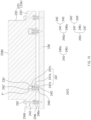
- FIG. 3 is a cross-sectional view illustrating the punch applied to the apparatus for manufacturing the pouch of FIG. 2 .
- the elastic part 140 may include a connection bar 141 and an elastic member 146 as illustrated in FIG. 3 .
- connection bar 141 may be a bar that is fixed to any one of the upper punch 131 and the lower punch 136 and is movably connected to the other one of the upper punch 131 and the lower punch 136 in a vertical direction with respect to the other one.
- FIG. 3 illustrates the connection bar 141 fixed to the lower punch 136 and movably connected to the upper punch 131.
- the lower punch 136 connected to the upper punch 131 by the connection bar 141 may also move in the vertical direction together with the upper punch 131.
- FIG. 3 when the lower punch 136 moves upward by external force, only the connection bar 141 fixed to the lower punch 136 may move upward together with the lower punch 136 without moving the upper punch 131.
- the elastic member 146 may be pressed, and during the pressing, the elastic member 146 may elastically support the lower punch 136.
- the impact applied to the lower punch 136 and the like may be alleviated.
- connection bar 141 may include a head 142 and a fixed bar 143 so as to be vertically movably connected to the upper punch 131 and fixed to the lower punch 136.
- the upper punch 131 may include an upper punch body 134 (including an upper block 132 and a lower block 133) defining an outer shape of the upper punch 131, and the head 142 may be disposed outside a top surface 134U of the upper punch body 134.
- the head 142 may have a diameter greater than that of a through-hole 135 so as not to be inserted into the through-hole 135 (e.g., a first through-hole 135a to be described later).
- a washer W may be disposed between the head 142 and the top surface 134U of the upper punch body 134. In this case, the head 142 may have a diameter greater than that of a central hole of the washer W passing through the fixed bar 143 to be described later.
- the upper punch 131 may include a through-hole 135 (e.g., a first through-hole 135a and a second through-hole 135b to be described later) passing through the upper punch body 134 from the top surface 134U to a bottom surface 134L of the upper punch body 134.
- the fixing bar 143 may extend downward from the head 142 to pass through the through-hole 135.
- a lower end of the fixed bar 143 which is exposed to a lower side of the upper punch body 134, may be fixed to the lower punch 136.
- the lower end of the fixed bar 143 provided to be pointed is exemplified, and a screw thread for screw-coupling with the lower punch 136 may be disposed at the pointed lower end of the fixed bar 143.
- the elastic member 146 is configured to provide elastic force of the elastic part 140 and may be, for example, a spring. The whole or a portion of the elastic member 146 may be disposed between the upper punch 131 and the lower punch 136.
- FIG. 3 illustrates an example in which a portion of the elastic member 146 is inserted into the second through-hole 135b to be described later, and a remaining portion of the elastic member 146 is disposed between the upper punch 131 and the lower punch 136.
- the elastic member 146 may be provided to surround the connection bar 141 as illustrated in FIG. 3 .
- the elastic member 146 When the elastic member 146 is disposed to surround the connection bar 141, the elastic member 146 may more stably support the lower punch 136 during the relative movement of the lower punch 136 with respect to the upper punch 131. However, on the other hand, the elastic member may be disposed separately from the connection bar.
- the elastic member 146 may be disposed to be seated in the second through-hole 135b of the first through-hole 135a and the second through-hole 135b defined in the upper punch body 134.
- the first through-hole 135a may be a hole passing through the upper punch body 134 from the top surface 134U of the upper punch body 134 to one point P between the top surface 134U and the bottom surface 134L of the upper punch body 134.
- the second through-hole 135b may have an inner diameter greater than that of the first through-hole 135a may a hole passing through the upper punch body 134 from the one point P to the bottom surface 134L of the upper punch body 134.
- the first through-hole 135a and the second through-hole 135b may communicate with each other.
- a jaw 135c may be disposed on a boundary between the first through-hole 135a and the second through-hole 135b.
- An upper end of the elastic member 146 may be inserted into the second through-hole 135b and be seated on the jaw 135c between the first and second through-holes 135a and 135b.
- the elastic member 146 may be stably disposed between the upper punch 131 and the lower punch 136.
- the apparatus 100 for manufacturing the pouch may include a stripper 150 for pressing and fixing the pouch film F as illustrated in FIG. 2 .
- the stripper 150 may be connected to a stripper cylinder 166 fixed to the upper die 120 so as to be indirectly fixed to the upper die 120 and may vertically move with respect to the upper die 120 according to an operation of the stripper cylinder 166.
- the stripper cylinder 166 may include a cylinder body 167 and a cylinder rod 168 that is reciprocated according to a hydraulic pressure supplied to the inside of the cylinder body 167.
- the stripper 150 may be connected to the cylinder rod 168.
- the punch 130 may move in the vertical direction by passing through the stripper 150 through a hole H defined in a central portion of the stripper 150.
- the lower die 110 may include the lower die body 112 and the nest 113 as illustrated in FIG. 2 .
- the lower die body 112 may be a block defining an outer appearance of the lower die 110.
- a forming groove 111 may be defined in the lower die body 112 so as to be recessed inward.
- the nest 113 may be provided inside the forming groove 111 to support the punch 130 moving to the forming groove 111.
- the punch 130 may be provided to move in the vertical direction inside the forming groove 111.
- a nest cylinder 170 for vertical movement of the nest 113 may be disposed on the lower die 110.
- FIGS. 4 to 8 are views for explaining a process of molding a pouch film using the apparatus for manufacturing the pouch of FIG. 2 .
- FIG. 4 illustrates a case in which the nest 113 disposed adjacent to an upper opening of a forming groove 111 moves downward.
- the nest 113 may move upward.
- a stripper 150 descends by a stripper cylinder 166.
- the stripper 150 may press a pouch film F disposed on a top surface 112U of a lower die body 112 to fix the pouch film F during molding of the pouch film F.
- the pouch film F disposed on the top surface 112U of the lower die body 112 may be elongated downward.
- the vacuum passage 114 of the lower die body 112 may communicate with a vacuum pump (not shown).
- the apparatus 100 for manufacturing the pouch may be applied to a vacuum elongation process as described above.
- a cup part 11 of the pouch may be more angular, for example, an angle between a bottom surface and a side surface of the cup part 11 may be close to 90 degrees.
- the angled pouch may increase in volume of an electrode assembly accommodated in the same volume to improve energy density of the battery.
- a depth of the cup part 11 may be substantially constant.
- the pouch film F may be fitted between an inner wall of the lower die body 112, which defines the forming groove 111, and the nest 113 due to shaking of the nest 113. This is undesirable because the outer appearance of the pouch is poor.
- the elastic member 146 for buffering since the elastic member 146 for buffering is not disposed on the nest 113, but disposed on the punch 130, the above problem does not occur.
- the punch 130 descends by the punch cylinder 161.
- the pouch film F is pressed, and thus, the cup part 11 of the pouch may be formed to be more angular.
- an impact occurring between the punch 130 and the nest 113 may be alleviated by the elastic part 140 of the punch 130.
- the lower punch 136 may move toward the upper punch 131 in a state of being elastically supported by the elastic part 140, and in this process, the impact occurring between the punch 130 and the nest 113 may be alleviated. This may be beneficial to the good outer appearance of the pouch or the lifetime of the apparatus for manufacturing the pouch.
- the punch 130 may be provided to move downward until the pouch film F is in close contact with a top surface of the nest 113.
- the pouch film F may be pressed in a state in which a gap (except for a gap due to the film) is not formed between the punch 130 and the nest 113, and thus, the outer appearance of the pouch is better molded.
- FIG. 9 is a cross-sectional view illustrating an apparatus for manufacturing a pouch according to Embodiment 2 of the present invention
- FIG. 10 is a cross-sectional view illustrating a punch applied to the apparatus for manufacturing the pouch of FIG. 9
- FIG. 11 is a rear view illustrating a state after a lower punch of the punch of FIG. 10 is removed.
- a manufacturing apparatus according to Embodiment 2 is different from the manufacturing apparatus according to Embodiment 1 in a punch.
- a punch 230 will be mainly described.
- the matters described in Embodiment 1 may be applied to Embodiment 2 in the same or similar manner.
- an apparatus 200 for manufacturing the pouch according to Embodiment 2 of the present invention includes a lower die 110, an upper die 120, and a punch 230.
- the lower die 110 may include a forming groove 111.
- the lower die 110 may include a nest 113 disposed in the forming groove 111.
- the punch 230 may include an upper punch 231 and a lower punch 236.
- the upper punch 231 may include an upper block 232 and a lower block 233.
- the apparatus 200 for manufacturing the pouch according to this embodiment may include a stripper 150 for fixing a pouch film.
- the punch 230 may include an elastic part 240.
- the elastic part 240 may include an outer elastic member 246o and an inner elastic member 246i as illustrated in FIGS. 9 and 11 .
- the outer elastic member 246o may be an elastic member disposed adjacent to an outer edge of the lower punch 236 (e.g., four vertexes of the lower punch with reference to FIG. 11 ), and the inner elastic member 246i may be an elastic member disposed adjacent to a center of the lower punch 236 rather than the outer elastic member 246o.
- FIG. 11 illustrates an example in which four outer elastic members 246o and four inner elastic members 246i are provided.
- FIG. 11 is a rear view illustrating a state after removing the lower punch 236 of the punch 230, but the outer edge and the center of the lower punch 236 may substantially correspond to an outer edge and a center of the upper punch 231.
- the punch 230 may include elastic members 246o and 246i adjacent to the outer edge of the lower punch 236 or the upper punch 231 and adjacent to the center of the lower punch 236 or the upper punch 231, respectively. Therefore, the lower punch 236 may be more stably supported through the elastic members 246o and 246i.
- connection bars 241 and 241' may also be disposed at the centers of the outer elastic member 246o and the inner elastic member 246i as in Embodiment 1.
- an elastic modulus of the outer elastic member 246o may be less than an elastic modulus of the inner elastic member 246i.
- the punch 230 may relatively strongly press a central portion on an area (e.g., an area corresponding to the forming groove) in which a cup part 11 will be formed in the pouch film F, and a peripheral portion may be relatively weakly pressed by the punch 230. This may assist to suppress an occurrence of a problem in the edge (a boundary between a bottom surface and a side surface) of the cup part 11 during molding the cup part 11. For reference, even if materials have the same elastic modulus, the above effect may be achieved by varying a degree of compression (e.g., by disposing the outer elastic member to be less pressed).
- An elastic part 240o (hereinafter, referred to as an outer elastic part) disposed adjacent to an outer edge of the lower punch 236 and an elastic part 240i (hereinafter, referred to an inner elastic part) disposed closer to a center of the lower punch 236 than the outer elastic part may have different structures as illustrated in FIGS. 9 and 10 .
- the outer elastic part 240o may have the same structure as the elastic part 140 according to Embodiment 1 as illustrated in FIG. 10 . That is, the outer elastic part 240o may include a connection bar 241, which is provided with a head 242 and a fixed bar 243, and an elastic member 246o. The outer elastic portion 240o may be disposed on a lower block 233 of the upper punch 231 having an inverted T-shaped cross-section.
- an inner elastic part 240i may be disposed in an area of the lower block 233, which corresponds to an upper block 232.
- the inner elastic part 240i may include a connection bar 241' and an elastic member 246i.
- the connection bar 241' may include a head 242' disposed inside a through-groove 235' formed in the upper punch body 234.
- the through groove 235' may be a groove formed to pass through the upper punch body 234 from one point P' between a top surface 234U and a bottom surface 234L of the upper punch body 234 to the bottom surface 234L of the upper punch body 234.
- connection bar 241' may include a fixed bar 243' that is formed with a diameter less than that of the head 242' and extends downward from the head 242' so as to be fixed to the lower punch 236 at a lower end thereof.
- An upper end of the elastic member 246i may be inserted into the through-groove 235' to be disposed below the head 242'.
- an area on which the upper block 232 and the lower block 233 overlap each other may be thicker than the lower block 233, and a top surface of the upper block 232 may be in contact with a bottom surface of the upper die 120.
- the inner elastic part 240i may preferably have a shape accommodated in the through-groove 235' of the upper punch body 234.
- the inner elastic part 240i may include a fixing member 247 inserted into and fixed to the through-groove 235' of the upper punch body 234.
- the fixing member 247 may include a body portion 247a inserted into the through-groove 235' and having an inverted U-shaped cross-section and an extension portion 247b horizontally extending outward from a lower end of the body portion 247a so as to be in close contact with the bottom surface 234L of the upper punch body 234.
- connection bar 241' and the elastic member 246i may be inserted into an inner space of the body portion 247a inserted into the through-groove 235'.
- a stopper 247c horizontally protruding inward may be formed in the inner space of the body portion 247a.
- the stopper 247c may prevent the head 242' of the connection bar 241' from being separated downward.
- the stopper 247c may be spaced a predetermined distance downward from a ceiling surface of the inner space of the body portion 247a so as to allow vertical movement of the connection bar 241'.
- An upper end of the elastic member 246i may be disposed below the stopper 247c.
- connection bar 241' and the elastic member 246i may be installed on the fixing member 247 in the state of being installed in the through-groove 235' of the upper punch body 234, and thus, the installation of the inner elastic part 240i may be facilitated.
Landscapes
- Engineering & Computer Science (AREA)
- Mechanical Engineering (AREA)
- Making Paper Articles (AREA)
- Blow-Moulding Or Thermoforming Of Plastics Or The Like (AREA)
- Sealing Battery Cases Or Jackets (AREA)
- Manufacturing & Machinery (AREA)
- Perforating, Stamping-Out Or Severing By Means Other Than Cutting (AREA)
Description
- The present application claims the benefit of the priority of
Korean Patent Application 10-2021-0117120, filed on September 02, 2021 - The present invention relates to an apparatus for manufacturing a pouch.
- In general, secondary batteries are chargeable and dischargeable unlike primary batteries that are not chargeable and are widely used in electronic devices such as mobile phones, notebook computers, camcorders, and the like, electric vehicles, or the like. Particularly, since a lithium secondary battery has larger capacity than a nickel-cadmium battery or a nickel-hydrogen battery and has a high energy density per unit weight, a degree of its utilization is rapidly increasing.
- A secondary battery is classified according to an electrode assembly having a positive electrode/separator/negative electrode structure. Representatively, exemplary examples of the electrode assembly may include a jelly-roll type (winding type) electrode assembly in which long sheet-shaped electrodes are wound with a separator therebetween, a stack-type electrode assembly in which a plurality of electrodes, which are cut into units, each of which has a predetermined size, are sequentially stacked with a separator therebetween, a stack-folding type electrode assembly in which bi-cells or full cells, which are stacked with a separator therebetween, are wound, and the like.
- In addition, such a secondary battery may be classified into a cylindrical battery or a prismatic battery in which an electrode assembly is built in a cylindrical or prismatic metal can and a pouch type battery in which an electrode assembly is built in a pouch type case provided as an aluminum lamination sheet.
-
FIG. 1 illustrates an example of a pouch-type secondary battery. A pouch-typesecondary battery 1 includes anelectrode assembly 20, in which electrodes and separators are alternately stacked, and apouch 10, into which the electrode assembly is inserted. In addition, the pouch includes acup part 11 of the pouch, which has a recessed shape so that the electrode assembly is directly accommodated. The cup part of the pouch may be provided with acup part 11L of a left pouch and acup part 11R of a right pouch to surround the electrode assembly at both sides. Aperipheral part 14 of the pouch is formed around the periphery of each of the cup parts of the pouch to seal the pouch from the outside. - The cup part of the pouch is usually molded by pressing a pouch film by using a punch. However, an impact may be applied to the punch or the like during such a pressing process. Such an impact may adversely affect the outer appearance of the pouch or the lifespan of the apparatus for manufacturing the pouch, and thus, it is preferable to effectively buffer the cup part.
- Document
US 2020/083493 A1 related to a pouch-type secondary battery having an increased energy density by reducing a dead space and an apparatus for forming a pouch film that is used for the pouch-type secondary battery. - Document
US 2020/282627 discusses a pouch molding method and apparatus, in which, when a cup part of a pouch is formed, elongation of a pouch film is uniformly maintained to prevent wrinkles from occurring in the cup part. - Document
JP 5 101906 B2 - Document
KR 2020 0052061 A - Document
US 2020/406528 A1 discusses a pouch forming apparatus and method, in which a non-sealing part formed when a pouch film, in which two cup parts are formed, is bent is reduced in area. - Document
KR 2014 0019933 A - Document
US 2014/234469 A1 relates to a device for shaping deep-drawn containers. - Document
CN 109 332 495 A relates to the technical field of presses, in particular to a press with high processing precision. - Document
US 2005/127566 A1 relates to complex sheeting of composite material, more exactly to the production of shaped structures or pieces with relatively thin wall elements, arranged in several planes to make. - An object of the prevent invention is to provide an apparatus for manufacturing a pouch, which is capable of effectively alleviating an impact applied to a punch while pressing a pouch film by the punch or an impact applied to a member that is in direct or indirect contact with the pouch.
- Another object of the present invention is to provide an apparatus for manufacturing a pouch, which is capable of better molding an outer appearance of the pouch.
- Another object of the present invention is to provide an apparatus for manufacturing a pouch, which is capable of more angularly molding a cup part and more uniformly molding a depth of the cup part.
- The present invention is defined by the features of
claim 1. In an embodiment, an apparatus for manufacturing a pouch includes a lower die provided with a forming groove for forming a cup part in a pouch film, an upper die disposed to be spaced upward from the lower die, and a punch supported by the upper die and configured to move toward the forming groove so as to press the pouch film to be disposed on the lower die, wherein the punch includes: an upper punch vertically movably connected to the upper die; a lower punch disposed to be spaced downward from the upper punch and configured to move together with the upper punch to press the pouch film; and an elastic part disposed between the upper punch and the lower punch to elastically support the lower punch. - In another embodiment, the elastic part may be provided to elastically press the lower punch downward.
- The elastic part includes a connection bar fixed to one of the upper punch and the lower punch and connected to the other one of the upper punch and the lower punch so as to be movable in a vertical direction with respect to the other one, and an elastic member provided to surround the connection bar between the upper punch and the lower punch.
- In further another embodiment, the upper punch may include an upper punch body configured to define an outer appearance of the upper punch, a first through-hole configured to pass through the upper punch body from a top surface of the upper punch body to one point between the top surface and a bottom surface of the upper punch body, and a second through-hole having an inner diameter greater than that of the first through-hole and configured to pass through the upper punch body from the one point to the bottom surface of the upper punch body, wherein the second through-hole communicates with the first through-hole.
- In further another embodiment, the connection bar may include a head disposed outside the top surface of the upper punch body, and a fixed bar extending downward from the head to pass through the first and second through-holes so as to be fixed to the lower punch at a lower end thereof.
- In further another embodiment, the head may have a diameter greater than that of the first through-hole so as not to be inserted into the first through-hole or have a diameter greater than that of a central hole of a washer disposed between the head and the top surface of the upper punch body.
- In further another embodiment, an upper end of the elastic member may be inserted into the second through-hole so as to be seated on a jaw provided by a difference in inner diameter between the first through-hole and the second through-hole.
- In further another embodiment, the upper punch may include an upper punch body configured to define an outer appearance of the upper punch, and a through-groove configured to pass through the upper punch body from one point between a top surface and a bottom surface of the upper punch body to the bottom surface of the upper punch body, and the connection bar may include a head disposed inside the through-groove, and a fixed bar having a diameter less than that of the head and extending downward from the head so as to be fixed to the lower punch at a lower end thereof, wherein an upper end of the elastic member may be inserted into the through-groove so as to be disposed below the head.
- In further another embodiment, the elastic part may include a body portion inserted into the through-groove of the upper punch and having an inverted U-shaped cross-section, and an extension portion horizontally extending outward from a lower end of the body portion so as to be in close contact with the bottom surface of the upper punch body, wherein the connection bar and the elastic member may be inserted into an inner space of the body portion inserted into the through-groove.
- In further another embodiment, the elastic part may include an outer elastic member disposed adjacent to an outer edge of the lower punch, and an inner elastic member disposed closer to a center of the lower punch than the outer elastic member.
- In further another embodiment, the outer elastic member may have an elastic modulus less than that of the inner elastic member.
- In further another embodiment, the lower die may include a lower die body which is configured to define an outer appearance of the lower die and in which the forming groove is defined, and a nest disposed to be vertically movable inside the forming groove and provided to support the punch moving into the forming groove.
- In further another embodiment, the punch may be configured to move downward until the pouch film is in close contact with a top surface of the nest.
- According to the present invention, since the punch pressing the pouch film includes the upper and lower punches, which are spaced apart from each other, and the elastic part disposed between the upper punch and the lower punch, the impact applied to the punch while being pressed by the punch or the impact applied to the member that is in direct or indirect contact with the punch may be effectively alleviated.
- In addition, according to the present invention, even though the nest is applied to the apparatus for manufacturing the pouch, the elastic member for the buffering is provided in the punch, but not the nest, the outer appearance of the pouch may be more better molded compared to the case in which the elastic member is provided in the nest.
- Furthermore, according to the present invention, the vacuum elongation process may be applied to the apparatus for manufacturing the pouch, and when the vacuum elongation process is applied, the cup part of the pouch may be more angularly molded due to the vacuum operation and the pressing of the punch, and the depth of the cup part may be more uniformly molded.
-
-
FIG. 1 is an exploded perspective view illustrating a pouch of a secondary battery and an electrode assembly embedded in the pouch. -
FIG. 2 is a cross-sectional view illustrating an apparatus for manufacturing a pouch according to Embodiment 1 of the present invention. -
FIG. 3 is a cross-sectional view illustrating a punch applied to the apparatus for manufacturing the pouch ofFIG. 2 . -
FIGS. 4 to 8 are views for explaining a process of molding a pouch film using the apparatus for manufacturing the pouch ofFIG. 2 . -
FIG. 9 is a cross-sectional view illustrating an apparatus for manufacturing a pouch according to Embodiment 2 of the present invention. -
FIG. 10 is a cross-sectional view illustrating a punch applied to the apparatus for manufacturing the pouch ofFIG. 9 . -
FIG. 11 is a rear view illustrating a state after a lower punch of the punch ofFIG. 10 is removed. - Hereinafter, preferred embodiments of the present invention will be described in detail with reference to the accompanying drawings so that those of ordinary skill in the art can easily carry out the present invention. However, the present invention may be implemented in several different forms and is not limited or restricted by the following examples.
- In order to clearly explain the present invention, detailed descriptions of portions that are irrelevant to the description or related known technologies that may unnecessarily obscure the gist of the present invention have been omitted, and in the present specification, reference symbols are added to components in each drawing. In this case, the same or similar reference numerals are assigned to the same or similar elements throughout the specification.
- Also, terms or words used in this specification and claims should not be restrictively interpreted as ordinary meanings or dictionary-based meanings, but should be interpreted as meanings and concepts conforming to the scope of the present invention on the basis of the principle that an inventor can properly define the concept of a term to describe and explain his or her invention in the best ways.
-
FIG. 2 is a cross-sectional view illustrating an apparatus for manufacturing a pouch according toEmbodiment 1 of the present invention. As illustrated inFIG. 2 , anapparatus 100 for manufacturing a pouch according toEmbodiment 1 of the present invention includes alower die 110, anupper die 120, and apunch 130. - The
lower die 110 may be a die in which a forminggroove 111 for forming a cup part 11 (seeFIG. 1 ) is defined. The forminggroove 111 may be a groove or hole defined by be recessed downward from atop surface 112U of alower die body 112 that defines an outer appearance of thelower die 110. A pouch film F (seeFIG. 4 ) disposed on thetop surface 112U of thelower die body 112 may be pressed to a lower side of the forminggroove 111 by thepunch 130 to be described later to form thecup part 11. - The
upper die 120 may be a die disposed to be spaced upward from thelower die 110. A connection pillar B may be provided between theupper die 120 and thelower die 110 to maintain a separation distance therebetween.Cylinders punch 130 or vertical movement of astripper 150 to be described later may be disposed on theupper die 120. - The
punch 130 may be a block for pressing the pouch film F disposed on thelower die 110. Thepunch 130 may be supported by theupper die 120. Thepunch 130 may be provided to move toward the forminggroove 111. For example, thepunch 130 may be connected to apunch cylinder 161 fixed to theupper die 120 so as to be indirectly fixed to theupper die 120 and may vertically move with respect to theupper die 120 according to the operation of thepunch cylinder 161. Thepunch cylinder 161 may include acylinder body 162 and acylinder rod 163 that is reciprocated according to a hydraulic pressure supplied to the inside of thecylinder body 162. Thepunch 130 may be connected to thecylinder rod 163. - The
punch 130 may include anupper punch 131. Theupper punch 131 may be a block vertically movably connected to theupper die 120. Thecylinder rod 163 of thepunch cylinder 161 may be coupled to theupper punch 131. Theupper punch 131 may include anupper block 132 disposed at an upper side, and alower block 133 disposed at a lower side and provided wider in a left and right direction than theupper block 132 inFIG. 2 . Theupper punch 131 may have an inverted T-shaped cross-section. - The
punch 130 may include alower punch 136. Thelower punch 136 may be a block disposed to be spaced downward from theupper punch 131. Thelower punch 136 may move together with theupper punch 131 according to the movement of theupper punch 131. During such movement, thelower punch 136 may be in contact with the pouch film F to press the pouch film F (seeFIG. 7 ). Thelower punch 136 is connected to theupper punch 131 by a predetermined bar and may move together with theupper punch 131 while being spaced apart from theupper punch 131. For example, thelower punch 136 may be connected to be spaced apart from theupper punch 131 by a fixed bar 143 (seeFIG. 3 ) to be described later. - The
punch 130 may include anelastic part 140 that elastically supports thelower punch 136 with respect to theupper punch 131. For example, when thelower punch 136 is pressed upward by anest 113 or the like to be described later while thelower punch 136 presses the pouch film F, theelastic part 140 may alleviate an impact applied to thelower punch 136 while pressing the elastic member 146 (seeFIG. 3 ) to be described (seeFIG. 3 ). - The
elastic part 140 may be provided to elastically press thelower punch 136 downward in a state of being supported by theupper punch 131 so as to buffer thelower punch 136. For example, theelastic member 146 of theelastic part 140 may be disposed between theupper punch 131 and thelower punch 136 in the pressed state. An amount of compression of theelastic member 146 may be determined according to a required degree of the buffering. - The
elastic part 140 may be disposed between theupper punch 131 and thelower punch 136. For example, the whole or portion of theelastic part 140 may be disposed between theupper punch 131 and thelower punch 136.FIG. 2 illustrates a case in which a portion of theelastic part 140 is disposed between theupper punch 131 and thelower punch 136. - In the
apparatus 100 for manufacturing the pouch according toEmbodiment 1 of the present invention, since thepunch 130 pressing the pouch film F includes theelastic part 140 disposed between theupper punch 131 and thelower punch 136, the impact applied to thepunch 130 while being pressed by thepunch 130 or the impact applied to member (e.g., thenest 113 to be described) that is in direct or indirect contact with thepunch 130 may be effectively alleviated. - The
elastic part 140 of this embodiment will be described in detail with reference toFIG. 3. FIG. 3 is a cross-sectional view illustrating the punch applied to the apparatus for manufacturing the pouch ofFIG. 2 . Theelastic part 140 may include aconnection bar 141 and anelastic member 146 as illustrated inFIG. 3 . - The
connection bar 141 may be a bar that is fixed to any one of theupper punch 131 and thelower punch 136 and is movably connected to the other one of theupper punch 131 and thelower punch 136 in a vertical direction with respect to the other one.FIG. 3 illustrates theconnection bar 141 fixed to thelower punch 136 and movably connected to theupper punch 131. - When the
upper punch 131 moves in the vertical direction inFIG. 3 , thelower punch 136 connected to theupper punch 131 by theconnection bar 141 may also move in the vertical direction together with theupper punch 131.FIG. 3 , when thelower punch 136 moves upward by external force, only theconnection bar 141 fixed to thelower punch 136 may move upward together with thelower punch 136 without moving theupper punch 131. Here, theelastic member 146 may be pressed, and during the pressing, theelastic member 146 may elastically support thelower punch 136. Thus, the impact applied to thelower punch 136 and the like may be alleviated. - The
connection bar 141 may include ahead 142 and a fixedbar 143 so as to be vertically movably connected to theupper punch 131 and fixed to thelower punch 136. - The
upper punch 131 may include an upper punch body 134 (including anupper block 132 and a lower block 133) defining an outer shape of theupper punch 131, and thehead 142 may be disposed outside atop surface 134U of theupper punch body 134. Thehead 142 may have a diameter greater than that of a through-hole 135 so as not to be inserted into the through-hole 135 (e.g., a first through-hole 135a to be described later). A washer W may be disposed between thehead 142 and thetop surface 134U of theupper punch body 134. In this case, thehead 142 may have a diameter greater than that of a central hole of the washer W passing through the fixedbar 143 to be described later. - The
upper punch 131 may include a through-hole 135 (e.g., a first through-hole 135a and a second through-hole 135b to be described later) passing through theupper punch body 134 from thetop surface 134U to abottom surface 134L of theupper punch body 134. Here, the fixingbar 143 may extend downward from thehead 142 to pass through the through-hole 135. A lower end of the fixedbar 143, which is exposed to a lower side of theupper punch body 134, may be fixed to thelower punch 136. InFIG. 3 , the lower end of the fixedbar 143 provided to be pointed is exemplified, and a screw thread for screw-coupling with thelower punch 136 may be disposed at the pointed lower end of the fixedbar 143. - The
elastic member 146 is configured to provide elastic force of theelastic part 140 and may be, for example, a spring. The whole or a portion of theelastic member 146 may be disposed between theupper punch 131 and thelower punch 136.FIG. 3 illustrates an example in which a portion of theelastic member 146 is inserted into the second through-hole 135b to be described later, and a remaining portion of theelastic member 146 is disposed between theupper punch 131 and thelower punch 136. Theelastic member 146 may be provided to surround theconnection bar 141 as illustrated inFIG. 3 . When theelastic member 146 is disposed to surround theconnection bar 141, theelastic member 146 may more stably support thelower punch 136 during the relative movement of thelower punch 136 with respect to theupper punch 131. However, on the other hand, the elastic member may be disposed separately from the connection bar. - The
elastic member 146 may be disposed to be seated in the second through-hole 135b of the first through-hole 135a and the second through-hole 135b defined in theupper punch body 134. The first through-hole 135a may be a hole passing through theupper punch body 134 from thetop surface 134U of theupper punch body 134 to one point P between thetop surface 134U and thebottom surface 134L of theupper punch body 134. The second through-hole 135b may have an inner diameter greater than that of the first through-hole 135a may a hole passing through theupper punch body 134 from the one point P to thebottom surface 134L of theupper punch body 134. The first through-hole 135a and the second through-hole 135b may communicate with each other. Since the first through-hole 135a and the second through-hole 135b have different inner diameters, a jaw 135c may be disposed on a boundary between the first through-hole 135a and the second through-hole 135b. An upper end of theelastic member 146 may be inserted into the second through-hole 135b and be seated on the jaw 135c between the first and second through-holes elastic member 146 may be stably disposed between theupper punch 131 and thelower punch 136. - The
apparatus 100 for manufacturing the pouch according to this embodiment may include astripper 150 for pressing and fixing the pouch film F as illustrated inFIG. 2 . Thestripper 150 may be connected to astripper cylinder 166 fixed to theupper die 120 so as to be indirectly fixed to theupper die 120 and may vertically move with respect to theupper die 120 according to an operation of thestripper cylinder 166. Thestripper cylinder 166 may include acylinder body 167 and acylinder rod 168 that is reciprocated according to a hydraulic pressure supplied to the inside of thecylinder body 167. Thestripper 150 may be connected to thecylinder rod 168. Thepunch 130 may move in the vertical direction by passing through thestripper 150 through a hole H defined in a central portion of thestripper 150. - The
lower die 110 according to this embodiment may include thelower die body 112 and thenest 113 as illustrated inFIG. 2 . Thelower die body 112 may be a block defining an outer appearance of thelower die 110. A forminggroove 111 may be defined in thelower die body 112 so as to be recessed inward. Thenest 113 may be provided inside the forminggroove 111 to support thepunch 130 moving to the forminggroove 111. In order to change the support position according to the degree to which thepunch 130 is inserted into the forminggroove 111, thepunch 130 may be provided to move in the vertical direction inside the forminggroove 111. For this, anest cylinder 170 for vertical movement of thenest 113 may be disposed on thelower die 110. - Hereinafter, a process of molding the pouch film F by the
apparatus 100 for manufacturing the pouch according to the present embodiment will be described with reference toFIGS. 4 to 8. FIGS. 4 to 8 are views for explaining a process of molding a pouch film using the apparatus for manufacturing the pouch ofFIG. 2 . - First, as illustrated in
FIG. 4 , anest 113 moves downward. A moving distance of thenest 113 may be determined based on an insertion depth of apunch 130.FIG. 4 illustrates a case in which thenest 113 disposed adjacent to an upper opening of a forminggroove 111 moves downward. When thenest 113 is disposed adjacent to a lower bottom surface of the forminggroove 111, thenest 113 may move upward. - Next, as illustrated in
FIG. 5 , astripper 150 descends by astripper cylinder 166. Thestripper 150 may press a pouch film F disposed on atop surface 112U of alower die body 112 to fix the pouch film F during molding of the pouch film F. - Next, as illustrated in
FIG. 6 , internal air of the forminggroove 111 is discharged through avacuum passage 114 formed in thelower die body 112. Thus, the pouch film F disposed on thetop surface 112U of thelower die body 112 may be elongated downward. For such vacuum elongation, thevacuum passage 114 of thelower die body 112 may communicate with a vacuum pump (not shown). - The
apparatus 100 for manufacturing the pouch according to this embodiment may be applied to a vacuum elongation process as described above. When the vacuum elongation process is applied, acup part 11 of the pouch may be more angular, for example, an angle between a bottom surface and a side surface of thecup part 11 may be close to 90 degrees. The angled pouch may increase in volume of an electrode assembly accommodated in the same volume to improve energy density of the battery. In addition, when the vacuum elongation process is applied, in the manufactured pouch, a depth of thecup part 11 may be substantially constant. - It may be considered to disposed an elastic member under the
nest 113 for buffering. However, if the elastic member is disposed under thenest 113, during the vacuum elongation or during movement of thenest 113, the pouch film F may be fitted between an inner wall of thelower die body 112, which defines the forminggroove 111, and thenest 113 due to shaking of thenest 113. This is undesirable because the outer appearance of the pouch is poor. However, in theapparatus 100 for manufacturing the pouch according to this embodiment, since theelastic member 146 for buffering is not disposed on thenest 113, but disposed on thepunch 130, the above problem does not occur. - Next, as illustrated in
FIG. 7 , thepunch 130 descends by thepunch cylinder 161. As a result, the pouch film F is pressed, and thus, thecup part 11 of the pouch may be formed to be more angular. Here, an impact occurring between thepunch 130 and thenest 113 may be alleviated by theelastic part 140 of thepunch 130. For example, when an impact is applied to thepunch 130 by thenest 113, as illustrated inFIG. 7 , thelower punch 136 may move toward theupper punch 131 in a state of being elastically supported by theelastic part 140, and in this process, the impact occurring between thepunch 130 and thenest 113 may be alleviated. This may be beneficial to the good outer appearance of the pouch or the lifetime of the apparatus for manufacturing the pouch. - The
punch 130 may be provided to move downward until the pouch film F is in close contact with a top surface of thenest 113. When moving as described above, the pouch film F may be pressed in a state in which a gap (except for a gap due to the film) is not formed between thepunch 130 and thenest 113, and thus, the outer appearance of the pouch is better molded. - Finally, as illustrated in
FIG. 8 , thepunch 130 ascends by thepunch cylinder 161. -
FIG. 9 is a cross-sectional view illustrating an apparatus for manufacturing a pouch according to Embodiment 2 of the present invention,FIG. 10 is a cross-sectional view illustrating a punch applied to the apparatus for manufacturing the pouch ofFIG. 9 , andFIG. 11 is a rear view illustrating a state after a lower punch of the punch ofFIG. 10 is removed. A manufacturing apparatus according to Embodiment 2 is different from the manufacturing apparatus according toEmbodiment 1 in a punch. Hereinafter, apunch 230 will be mainly described. For reference, the matters described inEmbodiment 1 may be applied to Embodiment 2 in the same or similar manner. - As illustrated in
FIG. 9 , anapparatus 200 for manufacturing the pouch according to Embodiment 2 of the present invention includes alower die 110, anupper die 120, and apunch 230. Thelower die 110 may include a forminggroove 111. Thelower die 110 may include anest 113 disposed in the forminggroove 111. Thepunch 230 may include anupper punch 231 and alower punch 236. Theupper punch 231 may include anupper block 232 and alower block 233. - The
apparatus 200 for manufacturing the pouch according to this embodiment may include astripper 150 for fixing a pouch film. - The
punch 230 according to this embodiment may include anelastic part 240. Theelastic part 240 according to this embodiment may include an outer elastic member 246o and an innerelastic member 246i as illustrated inFIGS. 9 and11 . The outer elastic member 246o may be an elastic member disposed adjacent to an outer edge of the lower punch 236 (e.g., four vertexes of the lower punch with reference toFIG. 11 ), and the innerelastic member 246i may be an elastic member disposed adjacent to a center of thelower punch 236 rather than the outer elastic member 246o.FIG. 11 illustrates an example in which four outer elastic members 246o and four innerelastic members 246i are provided. For reference,FIG. 11 is a rear view illustrating a state after removing thelower punch 236 of thepunch 230, but the outer edge and the center of thelower punch 236 may substantially correspond to an outer edge and a center of theupper punch 231. - The
punch 230 according to this embodiment may includeelastic members 246o and 246i adjacent to the outer edge of thelower punch 236 or theupper punch 231 and adjacent to the center of thelower punch 236 or theupper punch 231, respectively. Therefore, thelower punch 236 may be more stably supported through theelastic members 246o and 246i. For reference, connection bars 241 and 241' (seeFIG. 10 ) may also be disposed at the centers of the outer elastic member 246o and the innerelastic member 246i as inEmbodiment 1. - In this embodiment, an elastic modulus of the outer elastic member 246o may be less than an elastic modulus of the inner
elastic member 246i. In this case, thepunch 230 may relatively strongly press a central portion on an area (e.g., an area corresponding to the forming groove) in which acup part 11 will be formed in the pouch film F, and a peripheral portion may be relatively weakly pressed by thepunch 230. This may assist to suppress an occurrence of a problem in the edge (a boundary between a bottom surface and a side surface) of thecup part 11 during molding thecup part 11. For reference, even if materials have the same elastic modulus, the above effect may be achieved by varying a degree of compression (e.g., by disposing the outer elastic member to be less pressed). - An elastic part 240o (hereinafter, referred to as an outer elastic part) disposed adjacent to an outer edge of the
lower punch 236 and anelastic part 240i (hereinafter, referred to an inner elastic part) disposed closer to a center of thelower punch 236 than the outer elastic part may have different structures as illustrated inFIGS. 9 and10 . - The outer elastic part 240o may have the same structure as the
elastic part 140 according toEmbodiment 1 as illustrated inFIG. 10 . That is, the outer elastic part 240o may include aconnection bar 241, which is provided with ahead 242 and a fixedbar 243, and an elastic member 246o. The outer elastic portion 240o may be disposed on alower block 233 of theupper punch 231 having an inverted T-shaped cross-section. - As illustrated in
FIG. 10 , an innerelastic part 240i may be disposed in an area of thelower block 233, which corresponds to anupper block 232. The innerelastic part 240i may include aconnection bar 241' and anelastic member 246i. Theconnection bar 241' may include a head 242' disposed inside a through-groove 235' formed in theupper punch body 234. Here, the through groove 235' may be a groove formed to pass through theupper punch body 234 from one point P' between atop surface 234U and abottom surface 234L of theupper punch body 234 to thebottom surface 234L of theupper punch body 234. Theconnection bar 241' may include a fixed bar 243' that is formed with a diameter less than that of the head 242' and extends downward from the head 242' so as to be fixed to thelower punch 236 at a lower end thereof. An upper end of theelastic member 246i may be inserted into the through-groove 235' to be disposed below the head 242'. - In the
upper punch 231, an area on which theupper block 232 and thelower block 233 overlap each other may be thicker than thelower block 233, and a top surface of theupper block 232 may be in contact with a bottom surface of theupper die 120. Thus, the innerelastic part 240i may preferably have a shape accommodated in the through-groove 235' of theupper punch body 234. - The inner
elastic part 240i may include a fixingmember 247 inserted into and fixed to the through-groove 235' of theupper punch body 234. The fixingmember 247 may include abody portion 247a inserted into the through-groove 235' and having an inverted U-shaped cross-section and anextension portion 247b horizontally extending outward from a lower end of thebody portion 247a so as to be in close contact with thebottom surface 234L of theupper punch body 234. - The
connection bar 241' and theelastic member 246i may be inserted into an inner space of thebody portion 247a inserted into the through-groove 235'. Astopper 247c horizontally protruding inward may be formed in the inner space of thebody portion 247a. Thestopper 247c may prevent the head 242' of theconnection bar 241' from being separated downward. Thestopper 247c may be spaced a predetermined distance downward from a ceiling surface of the inner space of thebody portion 247a so as to allow vertical movement of theconnection bar 241'. An upper end of theelastic member 246i may be disposed below thestopper 247c. - When the fixing
member 247 is provided, theconnection bar 241' and theelastic member 246i may be installed on the fixingmember 247 in the state of being installed in the through-groove 235' of theupper punch body 234, and thus, the installation of the innerelastic part 240i may be facilitated.
Claims (12)
- An apparatus (100; 200) for manufacturing a pouch, the apparatus (100) comprising:a lower die (110) provided with a forming groove (111) for forming a cup part (11) in a pouch film (F);an upper die (120) disposed to be spaced upward from the lower die (110); anda punch (130; 230) supported by the upper die (120) and configured to move toward the forming groove (111) so as to press the pouch film (F) to be disposed on the lower die (110),wherein the punch (130; 230) comprises:an upper punch (131; 231) vertically movably connected to the upper die (120);a lower punch (136; 236) disposed to be spaced downward from the upper punch (131; 231) and configured to move together with the upper punch (131; 231) to press the pouch film (F);an elastic part (140; 240) disposed between the upper punch (131; 231) and the lower punch (136; 236) to elastically support the lower punch (136; 236);characterized in thatthe elastic part (140; 240) comprises:a connection bar (141; 241; 241') fixed to any one of the upper punch (131; 231) and the lower punch (136; 236) and connected to the other one of the upper punch (131; 231) and the lower punch (136; 236) so as to be movable in a vertical direction with respect to the other one; andan elastic member (146; 246o; 246i) provided to surround the connection bar (141; 241; 241') between the upper punch (131; 231) and the lower punch (136; 236).
- The apparatus (100; 200) of claim 1, wherein the elastic part (140; 240) is provided to elastically press the lower punch (136; 236) downward.
- The apparatus (100; 200) of claim 1, wherein the upper punch (131; 231) comprises:an upper punch body (134; 234) configured to define an outer appearance of the upper punch (131);a first through-hole (135a) configured to pass through the upper punch body (134) from a top surface of the upper punch body (134) to one point between the top surface and a bottom surface of the upper punch body (134; 234); anda second through-hole (135b) having an inner diameter greater than that of the first through-hole (135a) and configured to pass through the upper punch body (134) from the one point to the bottom surface of the upper punch body (134; 234), wherein the second through-hole (135b) communicates with the first through-hole (135a).
- The apparatus (100; 200) of claim 3, wherein the connection bar (141; 241) comprises:a head (142; 242) disposed outside the top surface of the upper punch body (134; 234); anda fixed bar (143; 243) extending downward from the head (142; 242) to pass through the first and second through-holes (135a, 135b) so as to be fixed to the lower punch (136; 236) at a lower end thereof.
- The apparatus (100; 200) of claim 4, wherein the head (142; 242) has a diameter greater than that of the first through-hole (135a) so as not to be inserted into the first through-hole (135a) or has a diameter greater than that of a central hole of a washer (W) disposed between the head (142; 242) and the top surface of the upper punch body (134; 234).
- The apparatus (100; 200) of claim 3, wherein an upper end of the elastic member (146; 246o) is inserted into the second through-hole (135b) so as to be seated on a jaw (135c) provided by a difference in inner diameter between the first through-hole (135a) and the second through-hole (135b).
- The apparatus (200) of claim 1, wherein the upper punch (231) comprises:an upper punch body (234) configured to define an outer appearance of the upper punch (231); anda through-groove (235') configured to pass through the upper punch body (234) from one point between a top surface and a bottom surface of the upper punch body (234) to the bottom surface of the upper punch body (234), andthe connection bar (241') comprises:a head (242') disposed inside the through-groove (235'); anda fixed bar (243') having a diameter less than that of the head (242') and extending downward from the head (242')so as to be fixed to the lower punch (236) at a lower end thereof,wherein an upper end of the elastic member (240i) is inserted into the through-groove (235') so as to be disposed below the head (242').
- The apparatus (200) of claim 7, wherein the elastic part (240) comprises:a body portion (247) inserted into the through-groove (235') of the upper punch (231) and having an inverted U-shaped cross-section; andan extension portion (247b) horizontally extending outward from a lower end of the body portion (247a) so as to be in close contact with the bottom surface of the upper punch body (234),wherein the connection bar (241') and the elastic member (240) are inserted into an inner space of the body portion (234) inserted into the through-groove (235').
- The apparatus (200) of claim 1, wherein the elastic part (240) comprises:an outer elastic member (246o) disposed adjacent to an outer edge of the lower punch (236); andan inner elastic member (246i) disposed closer to a center of the lower punch (236) than the outer elastic member (246o).
- The apparatus (200) of claim 9, wherein the outer elastic member (246o) has an elastic modulus less than that of the inner elastic member (246i).
- The apparatus (100; 200) of claim 1, wherein the lower die (136; 236) comprises:a lower die body (112) which is configured to define an outer appearance of the lower die (136) and in which the forming groove (111) is defined; anda nest (113) disposed to be vertically movable inside the forming groove (111) and provided to support the punch (130; 230) moving into the forming groove (111).
- The apparatus (100; 200) of claim 11, wherein the punch (130; 230) is configured to move downward until the pouch film (F) is in close contact with a top surface of the nest (113) .
Applications Claiming Priority (2)
| Application Number | Priority Date | Filing Date | Title |
|---|---|---|---|
| KR1020210117120A KR20230034477A (en) | 2021-09-02 | 2021-09-02 | Manufacturing device for pouch |
| PCT/KR2022/013208 WO2023033594A1 (en) | 2021-09-02 | 2022-09-02 | Pouch manufacturing apparatus |
Publications (3)
| Publication Number | Publication Date |
|---|---|
| EP4382280A1 EP4382280A1 (en) | 2024-06-12 |
| EP4382280A4 EP4382280A4 (en) | 2024-11-06 |
| EP4382280B1 true EP4382280B1 (en) | 2025-05-07 |
Family
ID=85411387
Family Applications (1)
| Application Number | Title | Priority Date | Filing Date |
|---|---|---|---|
| EP22865096.6A Active EP4382280B1 (en) | 2021-09-02 | 2022-09-02 | Pouch manufacturing apparatus |
Country Status (8)
| Country | Link |
|---|---|
| US (1) | US20250018621A1 (en) |
| EP (1) | EP4382280B1 (en) |
| JP (1) | JP7852948B2 (en) |
| KR (1) | KR20230034477A (en) |
| CN (1) | CN117940267A (en) |
| ES (1) | ES3036673T3 (en) |
| HU (1) | HUE072187T2 (en) |
| WO (1) | WO2023033594A1 (en) |
Families Citing this family (1)
| Publication number | Priority date | Publication date | Assignee | Title |
|---|---|---|---|---|
| KR102751459B1 (en) * | 2022-12-26 | 2025-01-08 | 고려대학교 산학협력단 | Cutting apparatus for membrane electrode assembly |
Family Cites Families (16)
| Publication number | Priority date | Publication date | Assignee | Title |
|---|---|---|---|---|
| JPS5140303Y2 (en) * | 1972-01-06 | 1976-10-01 | ||
| JPS5919009B2 (en) * | 1977-11-09 | 1984-05-02 | 積水化成流工業株式会社 | Deep drawing method and device using foam sheet |
| JPS604019A (en) * | 1983-06-23 | 1985-01-10 | Kishimoto Akira | Preparation of container with flange part |
| FR2863543B1 (en) * | 2003-12-16 | 2007-11-02 | Airbus France | METHOD FOR HOT STAMPING FORMING OF COMPLEX TOLERIE COMPONENT PIECES OF COMPOSITE MATERIAL AND TOOLING FOR IMPLEMENTING IT |
| JP5101906B2 (en) * | 2007-03-06 | 2012-12-19 | 昭和電工パッケージング株式会社 | Battery case molding method and molding apparatus |
| PL2574410T3 (en) * | 2011-10-01 | 2014-09-30 | Amcor Flexibles Zutphen B V | Device for forming deep-drawn containers |
| KR101443832B1 (en) * | 2012-08-07 | 2014-09-23 | 주식회사 엘지화학 | A manufacturing Apparatus for Secondary Battery Case and Method for preparation of the same |
| CN204620866U (en) * | 2015-05-11 | 2015-09-09 | 南通柯瑞特机械制造有限公司 | A kind of vacuum packing machine shell Bending Mould |
| CN106140947B (en) * | 2016-08-11 | 2018-07-03 | 佛山市鑫昌富诚汽车消声器制造有限公司 | The manufacturing device of impedance composite muffler |
| KR102075618B1 (en) * | 2017-09-14 | 2020-02-10 | 주식회사 엘지화학 | Pouch type secondary battery and Apparatus for forming Pouch film |
| KR102176631B1 (en) * | 2017-11-28 | 2020-11-09 | 주식회사 엘지화학 | The Method And The Apparatus For Forming Pouch |
| KR102245128B1 (en) * | 2018-01-30 | 2021-04-28 | 주식회사 엘지화학 | The Apparatus And The Method For Forming Pouch |
| CN109176723B (en) * | 2018-08-30 | 2020-11-06 | 中宁县智才技术服务有限公司 | Punching machine for soft package lithium battery outer package aluminum plastic film |
| KR102667401B1 (en) * | 2018-11-06 | 2024-05-21 | 주식회사 엘지에너지솔루션 | The Apparatus And The Method For Forming Pouch |
| EP3806233B1 (en) | 2018-11-09 | 2023-11-22 | LG Energy Solution, Ltd. | Pouch forming device |
| CN109332495A (en) * | 2018-11-15 | 2019-02-15 | 江苏纽克光谱科技有限公司 | A kind of press machine that machining accuracy is high |
-
2021
- 2021-09-02 KR KR1020210117120A patent/KR20230034477A/en active Pending
-
2022
- 2022-09-02 ES ES22865096T patent/ES3036673T3/en active Active
- 2022-09-02 US US18/688,456 patent/US20250018621A1/en active Pending
- 2022-09-02 HU HUE22865096A patent/HUE072187T2/en unknown
- 2022-09-02 WO PCT/KR2022/013208 patent/WO2023033594A1/en not_active Ceased
- 2022-09-02 EP EP22865096.6A patent/EP4382280B1/en active Active
- 2022-09-02 JP JP2024513806A patent/JP7852948B2/en active Active
- 2022-09-02 CN CN202280059205.XA patent/CN117940267A/en active Pending
Also Published As
| Publication number | Publication date |
|---|---|
| EP4382280A1 (en) | 2024-06-12 |
| JP2024531531A (en) | 2024-08-29 |
| WO2023033594A1 (en) | 2023-03-09 |
| KR20230034477A (en) | 2023-03-10 |
| ES3036673T3 (en) | 2025-09-23 |
| CN117940267A (en) | 2024-04-26 |
| US20250018621A1 (en) | 2025-01-16 |
| EP4382280A4 (en) | 2024-11-06 |
| JP7852948B2 (en) | 2026-04-28 |
| HUE072187T2 (en) | 2025-10-28 |
Similar Documents
| Publication | Publication Date | Title |
|---|---|---|
| KR101467859B1 (en) | Battery Case for Secondary Battery | |
| CN104303330B (en) | Battery container for secondary cell | |
| KR102131739B1 (en) | Pouch forming method and pouch forming device | |
| US11876162B2 (en) | Pouch forming method and pouch forming device | |
| US10461356B2 (en) | Jig having variable structure depending on size of receiving portion of case | |
| CN114303278B (en) | Pouch-type battery case, equipment for manufacturing pouch-type battery case, and pouch-type secondary battery | |
| KR100586896B1 (en) | Molding apparatus for secondary battery pouch | |
| EP4234196B1 (en) | Secondary battery pouch manufacturing apparatus | |
| EP4382280B1 (en) | Pouch manufacturing apparatus | |
| CN1622363A (en) | Sealed prismatic battery | |
| EP4155045A1 (en) | Pouch, apparatus for molding pouch, and method for manufacturing secondary battery comprising pouch | |
| US12318991B2 (en) | Pouch case manufacturing device and manufacturing method of pouch case | |
| KR102944481B1 (en) | Forming apparatus for pouche | |
| EP4696484A1 (en) | Pouch forming apparatus | |
| US12337368B2 (en) | Apparatus for manufacturing pouch of secondary battery | |
| EP4663378A1 (en) | Apparatus for molding pouch for secondary battery and method for manufacturing pouch-type secondary battery using same | |
| EP4674596A1 (en) | Molding device | |
| KR20150113582A (en) | Method for Preparation of Battery Case Using Extruding and Deep Drawing | |
| US20260051573A1 (en) | Pouch Type Battery Case and Apparatus for Forming the Same |
Legal Events
| Date | Code | Title | Description |
|---|---|---|---|
| STAA | Information on the status of an ep patent application or granted ep patent |
Free format text: STATUS: THE INTERNATIONAL PUBLICATION HAS BEEN MADE |
|
| PUAI | Public reference made under article 153(3) epc to a published international application that has entered the european phase |
Free format text: ORIGINAL CODE: 0009012 |
|
| STAA | Information on the status of an ep patent application or granted ep patent |
Free format text: STATUS: REQUEST FOR EXAMINATION WAS MADE |
|
| 17P | Request for examination filed |
Effective date: 20240304 |
|
| AK | Designated contracting states |
Kind code of ref document: A1 Designated state(s): AL AT BE BG CH CY CZ DE DK EE ES FI FR GB GR HR HU IE IS IT LI LT LU LV MC MK MT NL NO PL PT RO RS SE SI SK SM TR |
|
| A4 | Supplementary search report drawn up and despatched |
Effective date: 20241007 |
|
| RIC1 | Information provided on ipc code assigned before grant |
Ipc: H01M 50/10 20210101ALN20240930BHEP Ipc: B29C 51/36 20060101ALN20240930BHEP Ipc: B29C 51/26 20060101ALN20240930BHEP Ipc: B29C 43/04 20060101ALN20240930BHEP Ipc: B29C 43/36 20060101ALI20240930BHEP Ipc: B29C 51/10 20060101ALI20240930BHEP Ipc: B29C 51/08 20060101AFI20240930BHEP |
|
| DAV | Request for validation of the european patent (deleted) | ||
| DAX | Request for extension of the european patent (deleted) | ||
| GRAP | Despatch of communication of intention to grant a patent |
Free format text: ORIGINAL CODE: EPIDOSNIGR1 |
|
| STAA | Information on the status of an ep patent application or granted ep patent |
Free format text: STATUS: GRANT OF PATENT IS INTENDED |
|
| GRAS | Grant fee paid |
Free format text: ORIGINAL CODE: EPIDOSNIGR3 |
|
| RIC1 | Information provided on ipc code assigned before grant |
Ipc: H01M 50/10 20210101ALN20250221BHEP Ipc: B29C 51/36 20060101ALN20250221BHEP Ipc: B29C 51/26 20060101ALN20250221BHEP Ipc: B29C 43/04 20060101ALN20250221BHEP Ipc: B29C 43/36 20060101ALI20250221BHEP Ipc: B29C 51/10 20060101ALI20250221BHEP Ipc: B29C 51/08 20060101AFI20250221BHEP |
|
| GRAA | (expected) grant |
Free format text: ORIGINAL CODE: 0009210 |
|
| STAA | Information on the status of an ep patent application or granted ep patent |
Free format text: STATUS: THE PATENT HAS BEEN GRANTED |
|
| INTG | Intention to grant announced |
Effective date: 20250305 |
|
| AK | Designated contracting states |
Kind code of ref document: B1 Designated state(s): AL AT BE BG CH CY CZ DE DK EE ES FI FR GB GR HR HU IE IS IT LI LT LU LV MC MK MT NL NO PL PT RO RS SE SI SK SM TR |
|
| REG | Reference to a national code |
Ref country code: GB Ref legal event code: FG4D |
|
| P01 | Opt-out of the competence of the unified patent court (upc) registered |
Free format text: CASE NUMBER: APP_16880/2025 Effective date: 20250407 |
|
| REG | Reference to a national code |
Ref country code: CH Ref legal event code: EP |
|
| REG | Reference to a national code |
Ref country code: DE Ref legal event code: R096 Ref document number: 602022014477 Country of ref document: DE |
|
| REG | Reference to a national code |
Ref country code: IE Ref legal event code: FG4D |
|
| PGFP | Annual fee paid to national office [announced via postgrant information from national office to epo] |
Ref country code: BE Payment date: 20250520 Year of fee payment: 4 |
|
| REG | Reference to a national code |
Ref country code: NL Ref legal event code: MP Effective date: 20250507 |
|
| REG | Reference to a national code |
Ref country code: ES Ref legal event code: FG2A Ref document number: 3036673 Country of ref document: ES Kind code of ref document: T3 Effective date: 20250923 |
|
| PG25 | Lapsed in a contracting state [announced via postgrant information from national office to epo] |
Ref country code: PT Free format text: LAPSE BECAUSE OF FAILURE TO SUBMIT A TRANSLATION OF THE DESCRIPTION OR TO PAY THE FEE WITHIN THE PRESCRIBED TIME-LIMIT Effective date: 20250908 Ref country code: FI Free format text: LAPSE BECAUSE OF FAILURE TO SUBMIT A TRANSLATION OF THE DESCRIPTION OR TO PAY THE FEE WITHIN THE PRESCRIBED TIME-LIMIT Effective date: 20250507 |
|
| PGFP | Annual fee paid to national office [announced via postgrant information from national office to epo] |
Ref country code: DE Payment date: 20250820 Year of fee payment: 4 |
|
| REG | Reference to a national code |
Ref country code: LT Ref legal event code: MG9D |
|
| PG25 | Lapsed in a contracting state [announced via postgrant information from national office to epo] |
Ref country code: NO Free format text: LAPSE BECAUSE OF FAILURE TO SUBMIT A TRANSLATION OF THE DESCRIPTION OR TO PAY THE FEE WITHIN THE PRESCRIBED TIME-LIMIT Effective date: 20250807 Ref country code: GR Free format text: LAPSE BECAUSE OF FAILURE TO SUBMIT A TRANSLATION OF THE DESCRIPTION OR TO PAY THE FEE WITHIN THE PRESCRIBED TIME-LIMIT Effective date: 20250808 |
|
| PG25 | Lapsed in a contracting state [announced via postgrant information from national office to epo] |
Ref country code: NL Free format text: LAPSE BECAUSE OF FAILURE TO SUBMIT A TRANSLATION OF THE DESCRIPTION OR TO PAY THE FEE WITHIN THE PRESCRIBED TIME-LIMIT Effective date: 20250507 Ref country code: PL Free format text: LAPSE BECAUSE OF FAILURE TO SUBMIT A TRANSLATION OF THE DESCRIPTION OR TO PAY THE FEE WITHIN THE PRESCRIBED TIME-LIMIT Effective date: 20250507 |
|
| REG | Reference to a national code |
Ref country code: AT Ref legal event code: MK05 Ref document number: 1792002 Country of ref document: AT Kind code of ref document: T Effective date: 20250507 |
|
| PG25 | Lapsed in a contracting state [announced via postgrant information from national office to epo] |
Ref country code: BG Free format text: LAPSE BECAUSE OF FAILURE TO SUBMIT A TRANSLATION OF THE DESCRIPTION OR TO PAY THE FEE WITHIN THE PRESCRIBED TIME-LIMIT Effective date: 20250507 |
|
| PGFP | Annual fee paid to national office [announced via postgrant information from national office to epo] |
Ref country code: HU Payment date: 20250929 Year of fee payment: 4 |
|
| PG25 | Lapsed in a contracting state [announced via postgrant information from national office to epo] |
Ref country code: HR Free format text: LAPSE BECAUSE OF FAILURE TO SUBMIT A TRANSLATION OF THE DESCRIPTION OR TO PAY THE FEE WITHIN THE PRESCRIBED TIME-LIMIT Effective date: 20250507 |
|
| PG25 | Lapsed in a contracting state [announced via postgrant information from national office to epo] |
Ref country code: AT Free format text: LAPSE BECAUSE OF FAILURE TO SUBMIT A TRANSLATION OF THE DESCRIPTION OR TO PAY THE FEE WITHIN THE PRESCRIBED TIME-LIMIT Effective date: 20250507 |
|
| PGFP | Annual fee paid to national office [announced via postgrant information from national office to epo] |
Ref country code: FR Payment date: 20250821 Year of fee payment: 4 |
|
| PG25 | Lapsed in a contracting state [announced via postgrant information from national office to epo] |
Ref country code: RS Free format text: LAPSE BECAUSE OF FAILURE TO SUBMIT A TRANSLATION OF THE DESCRIPTION OR TO PAY THE FEE WITHIN THE PRESCRIBED TIME-LIMIT Effective date: 20250807 |
|
| PG25 | Lapsed in a contracting state [announced via postgrant information from national office to epo] |
Ref country code: IS Free format text: LAPSE BECAUSE OF FAILURE TO SUBMIT A TRANSLATION OF THE DESCRIPTION OR TO PAY THE FEE WITHIN THE PRESCRIBED TIME-LIMIT Effective date: 20250907 |
|
| REG | Reference to a national code |
Ref country code: HU Ref legal event code: AG4A Ref document number: E072187 Country of ref document: HU |
|
| PG25 | Lapsed in a contracting state [announced via postgrant information from national office to epo] |
Ref country code: LV Free format text: LAPSE BECAUSE OF FAILURE TO SUBMIT A TRANSLATION OF THE DESCRIPTION OR TO PAY THE FEE WITHIN THE PRESCRIBED TIME-LIMIT Effective date: 20250507 |
|
| PG25 | Lapsed in a contracting state [announced via postgrant information from national office to epo] |
Ref country code: DK Free format text: LAPSE BECAUSE OF FAILURE TO SUBMIT A TRANSLATION OF THE DESCRIPTION OR TO PAY THE FEE WITHIN THE PRESCRIBED TIME-LIMIT Effective date: 20250507 Ref country code: SM Free format text: LAPSE BECAUSE OF FAILURE TO SUBMIT A TRANSLATION OF THE DESCRIPTION OR TO PAY THE FEE WITHIN THE PRESCRIBED TIME-LIMIT Effective date: 20250507 |
|
| PG25 | Lapsed in a contracting state [announced via postgrant information from national office to epo] |
Ref country code: CZ Free format text: LAPSE BECAUSE OF FAILURE TO SUBMIT A TRANSLATION OF THE DESCRIPTION OR TO PAY THE FEE WITHIN THE PRESCRIBED TIME-LIMIT Effective date: 20250507 |
|
| PG25 | Lapsed in a contracting state [announced via postgrant information from national office to epo] |
Ref country code: EE Free format text: LAPSE BECAUSE OF FAILURE TO SUBMIT A TRANSLATION OF THE DESCRIPTION OR TO PAY THE FEE WITHIN THE PRESCRIBED TIME-LIMIT Effective date: 20250507 |
|
| PG25 | Lapsed in a contracting state [announced via postgrant information from national office to epo] |
Ref country code: SK Free format text: LAPSE BECAUSE OF FAILURE TO SUBMIT A TRANSLATION OF THE DESCRIPTION OR TO PAY THE FEE WITHIN THE PRESCRIBED TIME-LIMIT Effective date: 20250507 |
|
| PG25 | Lapsed in a contracting state [announced via postgrant information from national office to epo] |
Ref country code: IT Free format text: LAPSE BECAUSE OF FAILURE TO SUBMIT A TRANSLATION OF THE DESCRIPTION OR TO PAY THE FEE WITHIN THE PRESCRIBED TIME-LIMIT Effective date: 20250507 |
|
| PGFP | Annual fee paid to national office [announced via postgrant information from national office to epo] |
Ref country code: ES Payment date: 20251007 Year of fee payment: 4 |
|
| REG | Reference to a national code |
Ref country code: DE Ref legal event code: R097 Ref document number: 602022014477 Country of ref document: DE |
|
| PG25 | Lapsed in a contracting state [announced via postgrant information from national office to epo] |
Ref country code: RO Free format text: LAPSE BECAUSE OF FAILURE TO SUBMIT A TRANSLATION OF THE DESCRIPTION OR TO PAY THE FEE WITHIN THE PRESCRIBED TIME-LIMIT Effective date: 20250507 |
|
| PLBE | No opposition filed within time limit |
Free format text: ORIGINAL CODE: 0009261 |
|
| STAA | Information on the status of an ep patent application or granted ep patent |
Free format text: STATUS: NO OPPOSITION FILED WITHIN TIME LIMIT |
|
| REG | Reference to a national code |
Ref country code: CH Ref legal event code: L10 Free format text: ST27 STATUS EVENT CODE: U-0-0-L10-L00 (AS PROVIDED BY THE NATIONAL OFFICE) Effective date: 20260318 |
|
| 26N | No opposition filed |
Effective date: 20260210 |