EP4382239A1 - Friction stir welding tool and welding method - Google Patents
Friction stir welding tool and welding method Download PDFInfo
- Publication number
- EP4382239A1 EP4382239A1 EP23199532.5A EP23199532A EP4382239A1 EP 4382239 A1 EP4382239 A1 EP 4382239A1 EP 23199532 A EP23199532 A EP 23199532A EP 4382239 A1 EP4382239 A1 EP 4382239A1
- Authority
- EP
- European Patent Office
- Prior art keywords
- fsw
- housing
- pin
- work pieces
- joint line
- Prior art date
- Legal status (The legal status is an assumption and is not a legal conclusion. Google has not performed a legal analysis and makes no representation as to the accuracy of the status listed.)
- Pending
Links
Images



Classifications
-
- B—PERFORMING OPERATIONS; TRANSPORTING
- B23—MACHINE TOOLS; METAL-WORKING NOT OTHERWISE PROVIDED FOR
- B23K—SOLDERING OR UNSOLDERING; WELDING; CLADDING OR PLATING BY SOLDERING OR WELDING; CUTTING BY APPLYING HEAT LOCALLY, e.g. FLAME CUTTING; WORKING BY LASER BEAM
- B23K20/00—Non-electric welding by applying impact or other pressure, with or without the application of heat, e.g. cladding or plating
- B23K20/12—Non-electric welding by applying impact or other pressure, with or without the application of heat, e.g. cladding or plating the heat being generated by friction; Friction welding
- B23K20/122—Non-electric welding by applying impact or other pressure, with or without the application of heat, e.g. cladding or plating the heat being generated by friction; Friction welding using a non-consumable tool, e.g. friction stir welding
- B23K20/1245—Non-electric welding by applying impact or other pressure, with or without the application of heat, e.g. cladding or plating the heat being generated by friction; Friction welding using a non-consumable tool, e.g. friction stir welding characterised by the apparatus
- B23K20/126—Workpiece support, i.e. backing or clamping
-
- B—PERFORMING OPERATIONS; TRANSPORTING
- B23—MACHINE TOOLS; METAL-WORKING NOT OTHERWISE PROVIDED FOR
- B23K—SOLDERING OR UNSOLDERING; WELDING; CLADDING OR PLATING BY SOLDERING OR WELDING; CUTTING BY APPLYING HEAT LOCALLY, e.g. FLAME CUTTING; WORKING BY LASER BEAM
- B23K20/00—Non-electric welding by applying impact or other pressure, with or without the application of heat, e.g. cladding or plating
- B23K20/12—Non-electric welding by applying impact or other pressure, with or without the application of heat, e.g. cladding or plating the heat being generated by friction; Friction welding
- B23K20/122—Non-electric welding by applying impact or other pressure, with or without the application of heat, e.g. cladding or plating the heat being generated by friction; Friction welding using a non-consumable tool, e.g. friction stir welding
- B23K20/1245—Non-electric welding by applying impact or other pressure, with or without the application of heat, e.g. cladding or plating the heat being generated by friction; Friction welding using a non-consumable tool, e.g. friction stir welding characterised by the apparatus
- B23K20/1255—Tools therefor, e.g. characterised by the shape of the probe
-
- B—PERFORMING OPERATIONS; TRANSPORTING
- B23—MACHINE TOOLS; METAL-WORKING NOT OTHERWISE PROVIDED FOR
- B23K—SOLDERING OR UNSOLDERING; WELDING; CLADDING OR PLATING BY SOLDERING OR WELDING; CUTTING BY APPLYING HEAT LOCALLY, e.g. FLAME CUTTING; WORKING BY LASER BEAM
- B23K20/00—Non-electric welding by applying impact or other pressure, with or without the application of heat, e.g. cladding or plating
- B23K20/12—Non-electric welding by applying impact or other pressure, with or without the application of heat, e.g. cladding or plating the heat being generated by friction; Friction welding
- B23K20/122—Non-electric welding by applying impact or other pressure, with or without the application of heat, e.g. cladding or plating the heat being generated by friction; Friction welding using a non-consumable tool, e.g. friction stir welding
- B23K20/123—Controlling or monitoring the welding process
- B23K20/1235—Controlling or monitoring the welding process with temperature control during joining
-
- B—PERFORMING OPERATIONS; TRANSPORTING
- B23—MACHINE TOOLS; METAL-WORKING NOT OTHERWISE PROVIDED FOR
- B23K—SOLDERING OR UNSOLDERING; WELDING; CLADDING OR PLATING BY SOLDERING OR WELDING; CUTTING BY APPLYING HEAT LOCALLY, e.g. FLAME CUTTING; WORKING BY LASER BEAM
- B23K20/00—Non-electric welding by applying impact or other pressure, with or without the application of heat, e.g. cladding or plating
- B23K20/12—Non-electric welding by applying impact or other pressure, with or without the application of heat, e.g. cladding or plating the heat being generated by friction; Friction welding
- B23K20/129—Non-electric welding by applying impact or other pressure, with or without the application of heat, e.g. cladding or plating the heat being generated by friction; Friction welding specially adapted for particular articles or work
-
- B—PERFORMING OPERATIONS; TRANSPORTING
- B23—MACHINE TOOLS; METAL-WORKING NOT OTHERWISE PROVIDED FOR
- B23K—SOLDERING OR UNSOLDERING; WELDING; CLADDING OR PLATING BY SOLDERING OR WELDING; CUTTING BY APPLYING HEAT LOCALLY, e.g. FLAME CUTTING; WORKING BY LASER BEAM
- B23K31/00—Processes relevant to this subclass, specially adapted for particular articles or purposes, but not covered by any single one of main groups B23K1/00 - B23K28/00
- B23K31/02—Processes relevant to this subclass, specially adapted for particular articles or purposes, but not covered by any single one of main groups B23K1/00 - B23K28/00 relating to soldering or welding
- B23K31/022—Making profiled bars with soldered or welded seams
-
- B—PERFORMING OPERATIONS; TRANSPORTING
- B23—MACHINE TOOLS; METAL-WORKING NOT OTHERWISE PROVIDED FOR
- B23K—SOLDERING OR UNSOLDERING; WELDING; CLADDING OR PLATING BY SOLDERING OR WELDING; CUTTING BY APPLYING HEAT LOCALLY, e.g. FLAME CUTTING; WORKING BY LASER BEAM
- B23K2101/00—Articles made by soldering, welding or cutting
- B23K2101/006—Vehicles
-
- B—PERFORMING OPERATIONS; TRANSPORTING
- B23—MACHINE TOOLS; METAL-WORKING NOT OTHERWISE PROVIDED FOR
- B23K—SOLDERING OR UNSOLDERING; WELDING; CLADDING OR PLATING BY SOLDERING OR WELDING; CUTTING BY APPLYING HEAT LOCALLY, e.g. FLAME CUTTING; WORKING BY LASER BEAM
- B23K2101/00—Articles made by soldering, welding or cutting
- B23K2101/04—Tubular or hollow articles
-
- B—PERFORMING OPERATIONS; TRANSPORTING
- B23—MACHINE TOOLS; METAL-WORKING NOT OTHERWISE PROVIDED FOR
- B23K—SOLDERING OR UNSOLDERING; WELDING; CLADDING OR PLATING BY SOLDERING OR WELDING; CUTTING BY APPLYING HEAT LOCALLY, e.g. FLAME CUTTING; WORKING BY LASER BEAM
- B23K2103/00—Materials to be soldered, welded or cut
- B23K2103/08—Non-ferrous metals or alloys
- B23K2103/10—Aluminium or alloys thereof
Definitions
- Embodiments of the present disclosure generally relate to friction stir welding two work pieces together to form a welded joint.
- elongated metal structures For example, aircraft manufacturers use elongated metal structures for passenger aircraft. These elongated metal structures can be up to or even greater than 40 feet in length. However, it is difficult to fabricate long, thin metal structures that achieve relatively tight dimensional tolerances and that provide desired strength and stiffness characteristics.
- One conventional fabrication process involves extruding metal into a desired shape, but the long, thin extrusions tend to experience distortion, such as twisting or bowing. It is exceedingly difficult to extrude thin, elongated hollow structures that provide desired strength and rigidity, and meet the tight dimensional tolerances.
- some applications may require certain metal compositions for the elongated metal structure that are inherently difficult to extrude.
- Another conventional fabrication process is fusion welding.
- fusion welding is not a realistic option for some material compositions due to undesirable reactions in the microstructure due to the extreme change in temperature which degrades the material properties.
- high strength aluminum alloy elongated structures may not be fabricated by fusion welding due to the aluminum alloy forming post-weld cracks.
- some elongated metal structures may be thicker and heavier than desired, which adds cost and weight to the aircraft or other application.
- the elongated metal structure may be composed of a high-strength aluminum alloy that is difficult to extrude and fusion weld.
- the thin walls may reduce material costs and weight, relative to bulkier elongated structures. The reduced weight may be particularly advantageous for aircraft applications.
- a friction stir welding (FSW) tool that includes a pin, a housing, and a shoulder.
- the pin is configured to extend through a joint line between edges of two work pieces.
- the pin rotates to perform a FSW process that welds the two work pieces together at the joint line.
- the housing is coupled to a distal end of the pin to enable rotation of the pin relative to the housing.
- the pin extends through a support surface of the housing.
- the support surface contacts respective inner surfaces of the work pieces during the FSW process.
- the shoulder surrounds the pin and is configured to be rotated during the FSW process.
- the shoulder contacts respective outer surfaces of the work pieces during the FSW process such that the work pieces are sandwiched between the shoulder and the support surface of the housing.
- Certain embodiments of the present disclosure provide a welding method that includes loading a FSW tool onto two elongated work pieces fixed in position relative to one another such that respective edges of the work pieces define a joint line therebetween.
- the FSW tool includes a pin that extends through the joint line, a housing coupled to a distal end of the pin, and a shoulder that surrounds the pin.
- the FSW tool is loaded such that the housing is disposed along a first side of the j oint line and the shoulder is disposed along a second side of the j oint line opposite the first side.
- the method includes performing a FSW process by at least rotating the pin and moving the FSW tool along a length of the joint line to form a welded joint.
- Certain embodiments of the present disclosure provide a welding assembly that includes a structure and a friction stir welding (FSW) tool.
- the structure is defined by two elongated work pieces fixed in place relative to each other.
- the structure includes a joint line defined between respective edges of the two elongated work pieces.
- the structure includes a cavity that extends a length of the joint line.
- the FSW tool includes a housing disposed within the cavity, a pin extending through the joint line and coupled to the housing, and a shoulder disposed outside of the cavity and surrounding the pin.
- the pin is configured to rotate relative to the housing and the joint line to perform a FSW process that welds the two elongated work pieces together at the joint line.
- the shoulder is configured to rotate relative to the housing and the joint line during the FSW process.
- Examples of the present disclosure provide a method and tool for performing friction stir welding (FSW) to secure two elongated work pieces together along a joint.
- the work pieces may be metal.
- the work pieces may be metal extrusions.
- the tool includes a pin that is coupled to a housing and extends from the housing. The pin is designed to extend through a joint line defined between opposing edges of the two work pieces.
- the tool includes a shoulder that surrounds a portion of the pin such that the joint line is between the shoulder and the housing.
- the pin and shoulder rotate relative to the housing and the work pieces.
- the rotation of the pin and shoulder exerts a frictional force on the work pieces, which heats the edges to a plastic state, below the melting point of the work pieces.
- the edges mix together when in the plastic, malleable state, and form a welded joint upon cooling and solidifying to integrally join the two work pieces.
- the product of the welding process is a weld structure.
- the FSW tool and method described herein may be used to fabricate weld structures that are both strong and lightweight.
- the strength may be attributable to the material composition and/or structural design of the weld structure.
- the FSW tool and method may be used to weld two work pieces composed of a high strength metal alloy. Some high strength metal alloys are not able to be welded by fusion due to the formation of defects, such as cracks.
- the FSW tool and method may be applicable with at least some of these "unweldable" alloys, such as high-strength aluminum alloys.
- the structural design of the weld structures may contribute to the strength based on the arrangement of interconnected walls.
- the work pieces in one or more embodiments described herein may be arranged to define an elongated, hollow box shape that extends the length of the work pieces.
- the hollow box may structurally support the shape of the weld structure, increasing the stiffness and strength of the weld structure relative to a structure that lacks an internal hollow box element.
- One advantage of the strength of the weld structure is that the walls of the weld structure can be relatively thin while still maintaining a designated strength parameter (e.g., stiffness, etc.).
- the walls of the weld structures described herein may be thinner than other known structures in the same or similar applications, which reduces material costs and weight. Providing a reduced weight structure is particularly beneficial for aerial applications, such as commercial aircraft.
- the structure formed using the FSW tool and method described herein may have better quality (e.g., better surface finish, better dimensional accuracy, less deformation, less defects, and/or the like) than other techniques for fabricating elongated structures, such as extruding the structure in its final shape, without welding.
- the weld structure that is formed by friction stir welding two work pieces is a track.
- the weld structure may be a seat track on a vehicle for securing passenger seats in place within the vehicle.
- the vehicle may be a road-based vehicle (e.g., bus, truck, van, etc.), an aerial vehicle (e.g., aircraft, helicopter, spacecraft, etc.), a rail-based vehicle (e.g., train), a marine vessel (e.g., cruise ship, yacht, etc.), or the like.
- multiple passenger seats may be secured to the seat track within a passenger cabin of the vehicle.
- the FSW device and method described herein may be designed to fabricate a seat track for an aircraft.
- the embodiments described herein are not limited to aircraft applications, and are not limited to seat tracks.
- the FSW device and method may be applied to form various different types of elongated structures for different vehicular and/or non-vehicular applications.
- FIG. 1 is a block diagram of a friction stir welding (FSW) machine 100 according to an embodiment.
- the FSW machine 100 includes a FSW tool 102, which is a tool that engages the work pieces to perform a FSW process and combine the work pieces at a welded joint.
- the FSW tool 102 includes a pin 104, a shoulder 106, and a housing 108.
- the pin 104 is mechanically connected (e.g., coupled) to an actuator that rotates the pin 104 during the FSW process.
- the FSW tool 102 may be a self-reacting type of FSW tool.
- the FSW tool 102 may include two opposing components that contain the pin 104 in a single assembly and move together along the length of the work pieces to create the weld.
- the work pieces may be sandwiched between the shoulder 106 and a top surface of the housing 108.
- the pin 104 may extend through the joint during the welding process.
- the actuator includes a first spindle 110 that is powered by one or more power sources 112 to rotate the pin 104.
- the power source(s) 112 may include a motor, a battery, a pneumatic tank that includes compressed gas, a hydraulic pump, and/or the like.
- the power source(s) 112 may be controlled based on control signals generated by a user input device that controls operation of the FSW machine 100.
- the spindle 110 and power source(s) 112 may control the rate at which the pin 104 rotates, and may vary the rate based on received control signals.
- the housing 108 is coupled to the pin 104.
- a distal segment of the pin 104 may extend into the housing 108.
- the pin 104 may rotate relative to the housing 108 (and the work pieces) during the FSW process.
- the housing 108 does not rotate relative to the work pieces during the FSW process.
- the housing 108 does not complete a full 360-degree rotation.
- the shoulder 106 is mechanically connected (e.g., coupled) to a second actuator that rotates the shoulder 106 during the FSW process.
- the second actuator may include a second spindle 114 that is powered by the one or more power sources 112 to rotate the shoulder 106.
- the rotation of the shoulder 106 may be independent of the rotation of the pin 104.
- the pin 104 may rotate at different times, a different direction, and/or a different rate than the shoulder 106.
- the shoulder 106 and the pin 104 may be controlled to concurrently rotate at the same rate (e.g., speed) and direction.
- the shoulder 106 may not be rotated during the FSW process. In that case, the pin 104 rotates relative to the shoulder 106, the housing 108, and the work pieces.
- the housing 108 of the FSW tool 102 may be connected to one or more cooling lines 116 which convey a coolant to and/or from the housing 108 to dissipate heat from the FSW tool 102.
- the heat may be generated from the frictional forces exerted by the FSW tool 102 on the work pieces and/or frictional forces between moving components within the FSW tool 102 itself.
- the coolant may be a fluid, such as a glycol solution.
- the coolant may be pumped through the cooling line(s) 116 via a cooling system 118.
- the FSW machine 100 may include a first cooling line that delivers the coolant to the housing 108 from the cooling system 118, and a second cooling line that returns the coolant from the housing 108 to the cooling system 118.
- the cooling line(s) 116 may be hoses, tubes, or the like.
- the FSW machine 100 lacks the cooling system 118 and coolant, and the cooling line(s) 116 are metal rods that passively conduct heat away from the housing 108.
- the FSW machine 100 may lack both the cooling system 118 and cooling line(s) 116.
- FIG. 2 is a perspective view of a weld structure 200 that is formed by the FSW machine 100 according to an embodiment.
- the weld structure 200 (also referred to herein as structure 200) is elongated and extends from a first end 202 of the structure 200 to a second end 204 of the structure 200, which is opposite the first end 202.
- the structure 200 may be linear along the length between the first and second ends 202, 204.
- the structure 200 may include a box-shaped portion 206 that defines an elongated cavity 208.
- the elongated cavity 208 may extend the entire length of the structure 200.
- the structure 200 may include one or more wing segments 210 that project from the box-shaped portion 206.
- the wing segments 210 may extend the length of the structure 200.
- the structure 200 has four wing segments 210.
- This cross-sectional shape of the structure 200 is enlarged in Figure 7 .
- the structure 200 may not be shown to scale in Figure 2 .
- the length of the structure 200 may be up to, or greater than, 20 feet, 40 feet, or the like.
- the walls of the box-shaped portion 206 and/or the wing segments 210 may be relatively thin. In an example, the thickness may be no greater than 0.25 inches, or even no greater than 0.125 inches.
- the structure 200 may have other cross-sectional shapes in other embodiments.
- the FSW machine 100 may weld two work pieces together to form the structure 200.
- a first work piece 212 and a second work piece 214 may be positioned relative to one another such that edges of the work pieces 212, 214 define one or more seams, referred to herein as j oint lines 216.
- the work pieces 212, 214 may be fixed in place via one or more fixtures.
- the structure 200 has two j oint lines 216 in the illustrated embodiment.
- the joint lines 216 may extend the length of the structure 200.
- the FSW tool 102 may travel along the length of the work pieces 212, 214, forming weld joints at the joint lines to integrally connect the two work pieces 212, 214 together and define the unitary weld structure 200 shown in Figure 2 .
- the FSW machine 100 may include a propulsion source 120 that moves the FSW tool 102 along the length of the work pieces 212, 214 during the FSW process.
- the propulsion source 120 may include a powered actuator, a robotic arm, a tool on a suspended track that pulls the FSW tool 102, a traction motor that powers rotation of wheels on the FSW tool 102 to drive along the work pieces 212, 214, and/or the like.
- the propulsion source 120 may control the movement of the FSW tool 102 during the FSW process at a designated and constant speed.
- the designated speed may be based on welding conditions to ensure that the FSW tool 102 provides sufficient attention to each section of the joint line to result in a successfully welded joint that is relatively uniform along the length.
- the welding conditions may include the rotational speed of the pin 104, the material properties of the work pieces 212, 214, the amount of heat dissipation by the coolant, and/or the like.
- the FSW tool 102 may be manually pushed or pulled along the length of the joint lines 216 by a human operator during the FSW process.
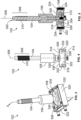
- Figure 3 is a perspective view of the FSW tool 102 according to an embodiment.
- Figure 4 is an elevation view of the FSW tool 102 shown in Figure 3.
- Figure 5 is a cross-sectional view of the FSW tool 102 shown in Figure 3 .
- the cross-section in Figure 5 is taken along line 5-5 in Figure 3 .
- the following description collectively refers to Figures 3 through 5 .
- the pin 104 is linear and extends from a proximal end 302 of the pin 104 to a distal end 304 of the pin 104 that is opposite the proximal end 302.
- the pin 104 rotates about a central axis 306 that extends through the pin 104 and is parallel with a length of the pin 104 between the proximal and distal ends 302, 304.
- a proximal segment 308 of the pin 104 connects to the first spindle 110 (or another type of actuator assembly that rotates the pin 104.
- the proximal segment 308 may include helical threads 310.
- a distal segment 312 of the pin 104 connects to the housing 108.
- the distal segment 312 may extend into the housing 108.
- the distal end 304 optionally may be within the housing 108 or may project beyond a bottom side 314 of the housing 108.
- the distal segment 312 may include helical threads or another feature for securing the pin 104 to the housing 108.
- the pin 104 projects from a top side 316 of the housing 108 such that the proximal segment 308 and the proximal end 302 are outside of the housing 108. In an embodiment, a majority of the length of the pin 302 is outside of the housing 108.
- the pin 104 may be composed of a high-strength metal material.
- the shoulder 106 surrounds the pin 104.
- the shoulder 106 may be shorter than the pin 104 such that the shoulder 106 surrounds only a section of the pin 104.
- the shoulder 106 may be a hollow shell as shown in Figure 5 .
- the shoulder 106 may be coaxial with the pin 104, and may rotate about the pin 104 (e.g., about the central axis 306).
- the shoulder 106 may be cylindrical.
- the shoulder 106 may not be directly connected to the housing 108.
- the shoulder 106 may be spaced apart from the housing 108 and may contact a different surface of the work pieces 212, 214 than the surface contacted by the housing 108, as described with reference to Figure 7 .
- the shoulder 106 may be composed of a metal material.
- the material composition of the shoulder 106 may be the same or different from the composition of the pin 104.
- the housing 108 is box-shaped.
- the housing 108 includes the top side 316, the bottom side 314, a first side wall 318, a second side wall 320, a first end wall 322, and a second end wall 324.
- the housing 108 may be an assembly of multiple components.
- the housing 108 may include a body 326 that defines the end walls 322, 324, or at least portions of the end walls 322, 324.
- a lower plate 328 may define at least a portion of the bottom side 314.
- An upper plate 330 may define at least a portion of the top side 316.
- the first and second side walls 318, 320 may be defined by wear pads 332.
- the body 326, upper plate 330, lower plate 328, and wear pads 332 may be secured together via fasteners 334.
- the housing 108 may have different components in alternative embodiments.
- the housing 108 may include the body 326 and the wear pads 332 without the discrete upper and lower plates 330, 328 because the body 326 may be formed to provide the functions of the plates 330, 328.
- a top surface of the body 326 may provide back side weld containment, and a portion of the body 326 may block the internal bearing from falling out of the housing 108.
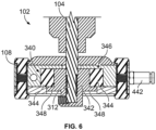
- Figure 6 is an enlarged cross-sectional view of a portion of the FSW tool 102 shown in Figure 5 .
- the distal segment 312 of the pin 104 is connected to a bearing assembly 340 within the housing 108.
- the bearing assembly 340 enables the pin 104 to rotate relative to the housing 108 while remaining mechanically connected to the housing 108.
- the bearing assembly 340 may include a bushing 342 that is fixedly secured to the pin 104.
- the distal segment 312 may screw into the bushing 342 and may be retained in the bushing 342 via a set screw or the like.
- the bearing assembly 340 may include a track or race 344 that is annular and surrounds a portion of the bushing 342.
- the race 344 contacts the bushing 342 and enables the bushing 342 to rotate relative to the race 344 with low friction.
- the race 344 may include ball bearings.
- the bearing assembly 340 is incorporated within an interior 346 of the housing 108.
- the bearing assembly 340 enables the pin 104 to rotate without forcing the housing 108 to rotate.
- the housing 108 does not rotate relative to the work pieces during the FSW process.
- the bearing race 344 may be mounted in place within a depression or cavity of the body 326 that is sized to accommodate the race 344.
- the bushing 342 may have a flange 348 that contacts a bottom side of the race 344 or the body 326 to retain the bushing 342 within the race 344.
- Figure 7 is an elevation view of a welding assembly 400 that includes the FSW tool 102 and the weld structure 200 according to an embodiment.
- Figure 7 shows the FSW tool 102 performing the FSW process on the work pieces 212, 214 that define the weld structure 200 according to an embodiment.
- the FSW tool 102 is positioned to weld a first joint line 216A that is defined by opposing edges 402, 404 of respective first flanges 406, 408 of the work pieces 212, 214.
- the first and second work pieces 212, 214 are replica copies of each other.
- the work pieces 212, 214 may have shapes that resemble the shape of the Greek letter Pi.
- the work pieces 212, 214 may also define a second joint line 216B that is across the elongated cavity 208 from the first joint line 216A.
- the FSW tool 102 is not positioned to weld the second joint line 216B in the illustrated orientation.
- the second joint line 216B is defined between edges of second flanges 410, 412 of the first and second work pieces 212, 214.
- the FSW tool 102 may be flipped relative to the structure 200 to weld the second joint line 216B.
- a second FSW tool 102 may be used in conjunction with the illustrated FSW tool 102 to weld the second joint line 216B, such as by moving the two FSW tools 102 in sequence with one in front of the other along the length of the structure 200.
- At least one of the work pieces 212, 214 may have a different shape in an alternative embodiment.
- the housing 108 of the FSW tool 102 may be sized and shaped to fit within the elongated cavity 208 of the structure 200.
- the housing 108 is disposed within the elongated cavity 208 in Figure 7 .
- the pin 104 is coupled to the housing 108 and extends through the first joint line 216A.
- the shoulder 106 is disposed outside of the elongated cavity 208.
- the pin 104 is rotated during the FSW process and contacts the edges 402, 404 of the first flanges 406, 408 at the first joint line 216A.
- the friction between the pin 104 and the edges 402, 404 heats the edges 402, 404 and welds the two first flanges 406, 408 of the work pieces 212, 214 together at the first joint line 216A.
- the shoulder 106 is rotated during the FSW process, concurrently with the rotation of the pin 104.
- the pin 104 and the shoulder 106 may rotate relative to the housing 108 and the joint line 216A, which are held stationary.
- the housing 108 may not be physically able to rotate within the elongated cavity 208.
- One or both of the side walls 318, 320 of the housing 108 may contact corresponding side surfaces 420, 422 of the elongated cavity 208.
- the side wall 318 may contact the side surface 420 of the first work piece 212
- the side wall 320 may contact the side surface 422 of the second work piece 214.
- the side walls 318, 320 are defined by the wear pads 332.
- the wear pads 332 may be designed to slide along the corresponding side surfaces 420, 422 with limited friction to reduce drag and/or low abrasion to avoid damaging the surface quality of the work pieces 212, 214.
- the wear pads 332 may be composed of nylon, high density plastic, or the like.
- the wear pads 332 may be replaceable.
- the flanges 406, 408 of the work pieces 212, 214 may be sandwiched between the shoulder 106 and the housing 108 during the FSW process.
- the housing 108 may include a support surface 424 that contacts respective inner (or lower) surfaces 426, 428 of the flanges 406, 408.
- the surfaces 426, 428 are inner surfaces because they face inside the elongated cavity 208.
- the support surface 424 of the housing 108 may provide a base that prevents the deformable edges 402, 404 along the joint line 216A from drooping due to gravity and/or other forces.
- the support surface 424 may be smooth.
- the welded joint may conform to the smooth shape of the support surface 424, resulting in a smooth surface finish along the inner surface of the welded j oint.
- the shoulder 106 may contact respective outer (or upper) surfaces 430, 432 of the flanges 406, 408 during the FSW process.
- the shoulder 106 may be able to slide along the length of the pin 104.
- the shoulder 106 may be biased towards the flanges 406, 408 due to gravitational force.
- a biasing member such as a spring, may exert a biasing force on the shoulder 106 towards the flanges 406, 408.
- the compressive forces provided by the shoulder 106 and the housing 108 may provide a desired shape and surface finish at the weld joint.
- a distal end 434 of the shoulder 106 may contact and slide along the outer surfaces 430, 432 as the shoulder 106 rotates during the FSW process.
- the friction provided by the active rotation of the shoulder 106 may enhance the quality of the surface finish.
- the housing 108 includes at least one port 440 that extends into the interior of the housing 108.
- the port 440 may be fluidly connected to one or more cooling channels that extend through the interior of the housing 108.
- the cooling channels may extend proximate to the bearing assembly 340 shown in Figure 6 .
- the cooling channels may be defined through the body 326 of the housing 108.
- the port 440 may receive a coolant that absorbs heat from the housing 108.
- the housing 108 includes a first port 440A and a second port 440B in the illustrated embodiment. Both ports 440A, 440B are disposed along a common end wall 322 of the housing 108 in Figure 7 .
- the ports 440A, 440B are spaced apart along a width of the housing 108.
- the housing 108 may include a different number of ports and/or at least some of the ports may be disposed on different end walls of the housing 108.
- a respective fitting 442 is installed within each port 440.
- the fitting 442 may be a quick connect fitting.
- the fitting 442 is configured to connect to a corresponding cooling line 116 (shown in Figure 1 ).
- Figure 8 is a perspective view of the FSW tool 102 shown without the shoulder 106.
- the segment of the pin 104 that aligns with and contacts the work pieces 212, 214 during the FSW process may have a non-uniform surface 450.
- the non-uniform surface 450 may include undulations, ridges, serrations, and/or the like.
- the non-uniform surface 450 may include smooth portions 452 and undulating portions 454 that alternate around a circumference of the pin 104.
- the housing 108 includes a raised platform 460 that protrudes beyond an upper surface 462 of the top side 316.
- the raised platform 460 defines the support surface 424 that contacts and supports the flanges 406, 408 during the FSW process.
- the raised platform 460 may have an elliptical, anvil shape.
- the raised platform 460 may be centrally located along the top side 316 of the housing 108, and is offset from a surrounding area of the top side 316.
- the pin 104 extends through the raised platform 460.
- the raised platform 460 is a component of the upper plate 330.
- the body 326 of the housing 108 may define the raised platform 460.
- the support surface 424 on the raised platform 460 may be relatively planar.
- the support surface 424 may be planar proximate to the pin 104, and may taper or curve along radial edges of the raised platform 460.
- the housing 108 does not include the raised platform 460.
- the support surface 424 may be defined by a central area of the top side 316 of the housing 108 that is flush with, or recessed below, a surrounding area of the top side 316.
- the body 326 may define a dovetail interface 470 with the lower plate 328 of the housing 108.
- the lower plate 328 may be assembled by sliding into the body 326 at the dovetail interface 470.
- the fasteners 334 may secure the lower plate 328 in place.
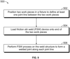
- FIG 9 is a flow chart 500 of a welding method according to an embodiment.
- the welding method may be a friction stir welding process.
- the welding method may be performed using the FSW machine 100 shown in Figure 1 .
- the method may be performed to weld two extruded, elongated work pieces together to form a unitary, one-piece weld structure.
- the weld structure may be relatively strong, stiff, and lightweight.
- the method optionally may include at least one additional step than shown, at least one fewer step than shown, and/or at least one different step than shown in Figure 9 .
- two elongated work pieces 212, 214 are positioned in a fixture 480 to secure the work pieces 212, 214 in fixed positions relative to one another.
- the work pieces 212, 214 may be oriented in the fixture 480 such that edges 402, 404 of first flanges 406, 408 of the work pieces 212, 214 oppose one another and define a joint line 216.
- the joint line 216 may extend a length of the elongated work pieces 212, 214.
- a FSW tool or tool 102 is loaded onto the two elongated work pieces 212, 214 held in the fixture 480.
- the FSW tool 102 may be mounted to a combined end segment of the two work pieces 212, 214 at one of the ends.
- the FSW tool 102 may be loaded onto the work pieces 212, 214 such that a pin 104 of the FSW tool 102 extends through the joint line 216, a housing 108 of the FSW tool 102 is disposed along a first side of the joint line 216, and a shoulder 106 of the FSW tool 106 is disposed along a second side of the joint line 216 opposite the first side.
- the end of the of the work pieces 212, 214 may include a pre-formed slot that aligns with the joint line 216 and accommodates the pin 104.
- the pre-formed slot enables setting up the FSW tool 102 in a designated position prior to rotating the pin 104.
- the two elongated work pieces 212, 214 in the fixture 480 define an elongated cavity 208 that extends a length of the work pieces 212, 214.
- the cavity 208 may be defined by four walls with open ends.
- the joint line 216 extends through one of the four walls.
- a second joint line 216 extends through another wall of the four walls.
- Loading the FSW tool 102 onto the two elongated work pieces at step 504 may include positioning the housing 108 within the elongated cavity 208.
- the housing 108 of the FSW tool 102 may be sized relative to the cavity 208 such that corresponding side surfaces 420, 422 of the work pieces 212, 214 block rotation of the housing 108 within the cavity 208.
- a FSW process is performed using the FSW tool 102.
- the FSW process may be performed at least in part by rotating the pin 104 and moving the FSW tool 102 along a length of the joint line 216 to form a welded joint. at the joint line 216.
- the FSW process may be performed by positioning the housing 108 such that a support surface 424 of the housing 108 contacts respective inner surfaces 426, 428 of the work pieces 212, 214 surrounding the pin 104 and the joint line 216.
- Performing the FSW process may include sandwiching opposing walls or flanges 406, 408 of the work pieces 212, 214 between a distal end 434 of the shoulder 106 and the support surface 424 of the housing 108.
- the FSW process may also include rotating the shoulder 106 relative to the housing 108 such that both the pin 104 and the shoulder 106 are rotated.
- the shoulder 106 may be rotated independently of the pin 104.
- the FSW process may include conveying a coolant to an interior of the housing 108 via a coolant line 116 that is connected to a port 440 of the housing 108. The coolant may absorb and dissipate heat from the FSW tool 102.
- the work pieces 212, 214 optionally may define both first and second joint lines 216A, 216B that extend parallel to one another along the length of the structure 200.
- the second joint line 216B may be located along an opposite side of the cavity 208 from the first joint line 216A.
- performing the FSW process may include forming a first welded joint along the first joint line 216A during a first time period by moving the FSW tool 102 along the length of the structure 200 with the pin 104 extending through the first joint line 216A.
- the method 500 may include reorienting the FSW tool 102 relative to the work pieces 212, 214 (after forming the first welded joint).
- the FSW tool 102 may be reoriented such that the pin 104 extends through the second joint line 216B.
- the FSW tool 102 may be flipped 180 degrees relative to the orientation of the work pieces 212, 214 in the fixture 480.
- the FSW process may include making a second pass of the FSW tool 102 along the length of the structure 200 to form a second welded j oint at the second j oint line 216B.
- the method may include utilizing two different FSW tools 102 to each form one of the two welded joints.
- a second FSW tool 102 may be loaded onto the work pieces 212, 214 next to the first FSW tool 102. This may include loading the two FSW tools 102 end-to-end within the elongated cavity 208 such that the second FSW tool trails the first FSW tool.
- the two FSW tools 102 may be copies or replicas of each other, such that the tools have the same components.
- the FSW machine 100 may be equipped with another set of spindles to simultaneously weld opposite joints.
- the two FSW tools may be flipped 180 degrees relative to one another.
- the pin 104 of the first FSW tool extends through the first joint line 216A
- the pin 104 of the second FSW tool extends through the second joint line 216B.
- the FSW process may be performed by rotating the pin 104 of the first FSW tool, rotating the pin 104 of the second FSW tool, moving the first FSW tool along the length of the first joint line 216A in a first direction to form the welded joint, and moving the second FSW tool along the length of the second joint line in the first direction to form a second welded joint.
- the first and second FSW tools may be concurrently moved with the second FSW tool trailing the first FSW tool.
- a friction stir welding (FSW) tool comprising:
- Clause 2 The FSW tool of Clause 1, wherein the housing includes a top side and a raised platform that protrudes beyond an upper surface of the top side, wherein the support surface is disposed along the raised platform.
- Clause 3 The FSW tool of Clause 1 or Clause 2, wherein the shoulder is coaxial with the pin and configured to be rotated about the pin to perform the FSW process.
- Clause 4 The FSW tool of any of Clauses 1-3, wherein the distal end of the pin is coupled to a bearing assembly within an interior of the housing.
- Clause 5 The FSW tool of any of Clauses 1-4, wherein the housing includes first and second side walls configured to contact corresponding side surfaces of an elongated cavity defined by the two work pieces during the FSW process.
- Clause 6 The FSW tool of Clause 5, wherein the first and second side walls include wear pads that contact the corresponding side surfaces.
- Clause 7 The FSW tool of any of Clauses 1-6, wherein the housing is box-shaped and is sized to fit within an elongated cavity defined by the two work pieces.
- Clause 8 The FSW tool of any of Clauses 1-7, wherein the housing includes at least a first port extending through an end wall of the housing and configured to receive a coolant to dissipate heat.
- Clause 9 The FSW tool of Clause 8, further comprising a quick connect fitting installed within the first port and configured to connect to a cooling line that conveys the coolant.
- Clause 10 The FSW tool of any of Clauses 1-9, further comprising a first spindle connected to the pin and a second spindle connected to the shoulder, wherein the first spindle rotates the pin relative to the housing and the work pieces during the FSW process, and the second spindle rotates the shoulder relative to the housing and the work pieces during the FSW process.
- a welding method comprising:
- Clause 12 The welding method of Clause 11, wherein the edges of the work pieces are defined by opposing flanges of the work pieces, and performing the FSW process includes sandwiching the opposing flanges between a distal end of the shoulder and a support surface of the housing.
- Clause 13 The welding method of Clause 11 or Clause 12, wherein performing the FSW process includes rotating the shoulder relative to the housing.
- Clause 14 The welding method of any of Clauses 11-13, wherein performing the FSW process includes positioning the housing such that a support surface of the housing contacts respective inner surfaces of the work pieces surrounding the pin and the joint line.
- Clause 15 The welding method of any of Clauses 11-14, wherein loading the FSW tool onto the two elongated work pieces comprises positioning the housing within a cavity defined by the work pieces that extends the length of the j oint line.
- Clause 16 The welding method of Clause 15, wherein the housing of the FSW tool is sized relative to the cavity such that corresponding side surfaces of the work pieces block rotation of the housing within the cavity.
- Clause 17 The welding method of any of Clauses 11-16, further comprising conveying a coolant to an interior of the housing while performing the FSW process, the coolant conveyed via a coolant line that is connected to a port of the housing.
- Clause 18 The welding method of any of Clauses 11-17, wherein the joint line is a first joint line, the welded joint is a first welded joint, and the work pieces define a second joint line therebetween that is parallel to and along an opposite side of a cavity from the first joint line, wherein performing the FSW process includes reorienting the FSW tool relative to the work pieces after forming the first welded joint and moving the FSW tool along the length of the second joint line to form a second welded joint.
- Clause 19 The welding method of any of Clauses 11-18, wherein the FSW tool is a first FSW tool, the joint line is a first joint line, the welded joint is a first welded joint, and the work pieces define a second joint line therebetween that is parallel to and along an opposite side of a cavity from the first joint line, the method further comprising:
- a welding assembly comprising:
- a structure, limitation, or element that is "configured to” perform a task or operation is particularly structurally formed, constructed, or adapted in a manner corresponding to the task or operation.
- an object that is merely capable of being modified to perform the task or operation is not “configured to” perform the task or operation as used herein.
Landscapes
- Engineering & Computer Science (AREA)
- Mechanical Engineering (AREA)
- Pressure Welding/Diffusion-Bonding (AREA)
Abstract
Description
- Embodiments of the present disclosure generally relate to friction stir welding two work pieces together to form a welded joint.
- Some industrial applications require elongated metal structures. For example, aircraft manufacturers use elongated metal structures for passenger aircraft. These elongated metal structures can be up to or even greater than 40 feet in length. However, it is difficult to fabricate long, thin metal structures that achieve relatively tight dimensional tolerances and that provide desired strength and stiffness characteristics. One conventional fabrication process involves extruding metal into a desired shape, but the long, thin extrusions tend to experience distortion, such as twisting or bowing. It is exceedingly difficult to extrude thin, elongated hollow structures that provide desired strength and rigidity, and meet the tight dimensional tolerances. Furthermore, some applications may require certain metal compositions for the elongated metal structure that are inherently difficult to extrude. Another conventional fabrication process is fusion welding. However, fusion welding is not a realistic option for some material compositions due to undesirable reactions in the microstructure due to the extreme change in temperature which degrades the material properties. For example, high strength aluminum alloy elongated structures may not be fabricated by fusion welding due to the aluminum alloy forming post-weld cracks. To accommodate these fabrication issues, some elongated metal structures may be thicker and heavier than desired, which adds cost and weight to the aircraft or other application.
- A need exists for a friction stir welding (FSW) tool and method that is able to reliably and repeatably produce a mechanically strong and stiff elongated metal structure that has thin walls. For example, the elongated metal structure may be composed of a high-strength aluminum alloy that is difficult to extrude and fusion weld. The thin walls may reduce material costs and weight, relative to bulkier elongated structures. The reduced weight may be particularly advantageous for aircraft applications.
- With those needs in mind, certain embodiments of the present disclosure provide a friction stir welding (FSW) tool that includes a pin, a housing, and a shoulder. The pin is configured to extend through a joint line between edges of two work pieces. The pin rotates to perform a FSW process that welds the two work pieces together at the joint line. The housing is coupled to a distal end of the pin to enable rotation of the pin relative to the housing. The pin extends through a support surface of the housing. The support surface contacts respective inner surfaces of the work pieces during the FSW process. The shoulder surrounds the pin and is configured to be rotated during the FSW process. The shoulder contacts respective outer surfaces of the work pieces during the FSW process such that the work pieces are sandwiched between the shoulder and the support surface of the housing.
- Certain embodiments of the present disclosure provide a welding method that includes loading a FSW tool onto two elongated work pieces fixed in position relative to one another such that respective edges of the work pieces define a joint line therebetween. The FSW tool includes a pin that extends through the joint line, a housing coupled to a distal end of the pin, and a shoulder that surrounds the pin. The FSW tool is loaded such that the housing is disposed along a first side of the j oint line and the shoulder is disposed along a second side of the j oint line opposite the first side. The method includes performing a FSW process by at least rotating the pin and moving the FSW tool along a length of the joint line to form a welded joint.
- Certain embodiments of the present disclosure provide a welding assembly that includes a structure and a friction stir welding (FSW) tool. The structure is defined by two elongated work pieces fixed in place relative to each other. The structure includes a joint line defined between respective edges of the two elongated work pieces. The structure includes a cavity that extends a length of the joint line. The FSW tool includes a housing disposed within the cavity, a pin extending through the joint line and coupled to the housing, and a shoulder disposed outside of the cavity and surrounding the pin. The pin is configured to rotate relative to the housing and the joint line to perform a FSW process that welds the two elongated work pieces together at the joint line. The shoulder is configured to rotate relative to the housing and the joint line during the FSW process.
- These and other features, aspects, and advantages of the present disclosure will become better understood when the following detailed description is read with reference to the accompanying drawings in which like numerals represent like parts throughout the drawings, wherein:
-
Figure 1 is a block diagram of a friction stir welding (FSW) machine according to an embodiment. -
Figure 2 is a perspective view of a weld structure that is formed by the FSW machine according to an embodiment. -
Figure 3 is a perspective view of the FSW tool 12 according to an embodiment. -
Figure 4 is an elevation view of the FSW device shown inFigure 3 . -
Figure 5 is a cross-sectional view of the FSW tool shown inFigure 3 . -
Figure 6 is an enlarged cross-sectional view of a portion of the FSW tool shown inFigure 5 . -
Figure 7 is an elevation view of a welding assembly that includes the FSW tool and the weld structure according to an embodiment. -
Figure 8 is a perspective view of the FSW tool shown without the shoulder. -
Figure 9 is a flow chart of a welding method according to an embodiment. - The foregoing summary, as well as the following detailed description of certain embodiments will be better understood when read in conjunction with the appended drawings. As used herein, an element or step recited in the singular and preceded by the word "a" or "an" should be understood as not necessarily excluding the plural of the elements or steps. Further, references to "one embodiment" are not intended to be interpreted as excluding the existence of additional embodiments that also incorporate the recited features. Moreover, unless explicitly stated to the contrary, embodiments "comprising" or "having" an element or a plurality of elements having a particular condition can include additional elements not having that condition.
- Examples of the present disclosure provide a method and tool for performing friction stir welding (FSW) to secure two elongated work pieces together along a joint. The work pieces may be metal. For example, the work pieces may be metal extrusions. The tool includes a pin that is coupled to a housing and extends from the housing. The pin is designed to extend through a joint line defined between opposing edges of the two work pieces. The tool includes a shoulder that surrounds a portion of the pin such that the joint line is between the shoulder and the housing. The pin and shoulder rotate relative to the housing and the work pieces. The rotation of the pin and shoulder exerts a frictional force on the work pieces, which heats the edges to a plastic state, below the melting point of the work pieces. The edges mix together when in the plastic, malleable state, and form a welded joint upon cooling and solidifying to integrally join the two work pieces. The product of the welding process is a weld structure.
- The FSW tool and method described herein may be used to fabricate weld structures that are both strong and lightweight. The strength may be attributable to the material composition and/or structural design of the weld structure. For example, the FSW tool and method may be used to weld two work pieces composed of a high strength metal alloy. Some high strength metal alloys are not able to be welded by fusion due to the formation of defects, such as cracks. The FSW tool and method may be applicable with at least some of these "unweldable" alloys, such as high-strength aluminum alloys. The structural design of the weld structures may contribute to the strength based on the arrangement of interconnected walls. For example, the work pieces in one or more embodiments described herein may be arranged to define an elongated, hollow box shape that extends the length of the work pieces. The hollow box may structurally support the shape of the weld structure, increasing the stiffness and strength of the weld structure relative to a structure that lacks an internal hollow box element. One advantage of the strength of the weld structure is that the walls of the weld structure can be relatively thin while still maintaining a designated strength parameter (e.g., stiffness, etc.). The walls of the weld structures described herein may be thinner than other known structures in the same or similar applications, which reduces material costs and weight. Providing a reduced weight structure is particularly beneficial for aerial applications, such as commercial aircraft. The structure formed using the FSW tool and method described herein may have better quality (e.g., better surface finish, better dimensional accuracy, less deformation, less defects, and/or the like) than other techniques for fabricating elongated structures, such as extruding the structure in its final shape, without welding.
- In one example, the weld structure that is formed by friction stir welding two work pieces is a track. For example, the weld structure may be a seat track on a vehicle for securing passenger seats in place within the vehicle. The vehicle may be a road-based vehicle (e.g., bus, truck, van, etc.), an aerial vehicle (e.g., aircraft, helicopter, spacecraft, etc.), a rail-based vehicle (e.g., train), a marine vessel (e.g., cruise ship, yacht, etc.), or the like. For example, multiple passenger seats may be secured to the seat track within a passenger cabin of the vehicle. In a specific example, the FSW device and method described herein may be designed to fabricate a seat track for an aircraft. The embodiments described herein are not limited to aircraft applications, and are not limited to seat tracks. The FSW device and method may be applied to form various different types of elongated structures for different vehicular and/or non-vehicular applications.
-
Figure 1 is a block diagram of a friction stir welding (FSW)machine 100 according to an embodiment. TheFSW machine 100 includes aFSW tool 102, which is a tool that engages the work pieces to perform a FSW process and combine the work pieces at a welded joint. TheFSW tool 102 includes apin 104, ashoulder 106, and ahousing 108. Thepin 104 is mechanically connected (e.g., coupled) to an actuator that rotates thepin 104 during the FSW process. In an example, theFSW tool 102 may be a self-reacting type of FSW tool. TheFSW tool 102 may include two opposing components that contain thepin 104 in a single assembly and move together along the length of the work pieces to create the weld. For example, the work pieces may be sandwiched between theshoulder 106 and a top surface of thehousing 108. Thepin 104 may extend through the joint during the welding process. - In the illustrated embodiment, the actuator includes a
first spindle 110 that is powered by one ormore power sources 112 to rotate thepin 104. The power source(s) 112 may include a motor, a battery, a pneumatic tank that includes compressed gas, a hydraulic pump, and/or the like. For example, the power source(s) 112 may be controlled based on control signals generated by a user input device that controls operation of theFSW machine 100. Thespindle 110 and power source(s) 112 may control the rate at which thepin 104 rotates, and may vary the rate based on received control signals. - The
housing 108 is coupled to thepin 104. For example, a distal segment of thepin 104 may extend into thehousing 108. Thepin 104 may rotate relative to the housing 108 (and the work pieces) during the FSW process. In an embodiment, thehousing 108 does not rotate relative to the work pieces during the FSW process. For example, thehousing 108 does not complete a full 360-degree rotation. In the illustrated embodiment, theshoulder 106 is mechanically connected (e.g., coupled) to a second actuator that rotates theshoulder 106 during the FSW process. For example, the second actuator may include asecond spindle 114 that is powered by the one ormore power sources 112 to rotate theshoulder 106. Optionally, the rotation of theshoulder 106 may be independent of the rotation of thepin 104. In an example, thepin 104 may rotate at different times, a different direction, and/or a different rate than theshoulder 106. In one setting, theshoulder 106 and thepin 104 may be controlled to concurrently rotate at the same rate (e.g., speed) and direction. In an alternative embodiment, theshoulder 106 may not be rotated during the FSW process. In that case, thepin 104 rotates relative to theshoulder 106, thehousing 108, and the work pieces. - Optionally, the
housing 108 of theFSW tool 102 may be connected to one ormore cooling lines 116 which convey a coolant to and/or from thehousing 108 to dissipate heat from theFSW tool 102. The heat may be generated from the frictional forces exerted by theFSW tool 102 on the work pieces and/or frictional forces between moving components within theFSW tool 102 itself. The coolant may be a fluid, such as a glycol solution. The coolant may be pumped through the cooling line(s) 116 via acooling system 118. Optionally, theFSW machine 100 may include a first cooling line that delivers the coolant to thehousing 108 from thecooling system 118, and a second cooling line that returns the coolant from thehousing 108 to thecooling system 118. The cooling line(s) 116 may be hoses, tubes, or the like. In a first alternative embodiment, theFSW machine 100 lacks thecooling system 118 and coolant, and the cooling line(s) 116 are metal rods that passively conduct heat away from thehousing 108. In a second alternative embodiment, theFSW machine 100 may lack both thecooling system 118 and cooling line(s) 116. -
Figure 2 is a perspective view of aweld structure 200 that is formed by theFSW machine 100 according to an embodiment. The weld structure 200 (also referred to herein as structure 200) is elongated and extends from afirst end 202 of thestructure 200 to asecond end 204 of thestructure 200, which is opposite thefirst end 202. Thestructure 200 may be linear along the length between the first and second ends 202, 204. Thestructure 200 may include a box-shapedportion 206 that defines anelongated cavity 208. Theelongated cavity 208 may extend the entire length of thestructure 200. Thestructure 200 may include one ormore wing segments 210 that project from the box-shapedportion 206. Thewing segments 210 may extend the length of thestructure 200. In the illustrated embodiment, thestructure 200 has fourwing segments 210. This cross-sectional shape of thestructure 200 is enlarged inFigure 7 . Thestructure 200 may not be shown to scale inFigure 2 . For example, the length of thestructure 200 may be up to, or greater than, 20 feet, 40 feet, or the like. The walls of the box-shapedportion 206 and/or thewing segments 210 may be relatively thin. In an example, the thickness may be no greater than 0.25 inches, or even no greater than 0.125 inches. Thestructure 200 may have other cross-sectional shapes in other embodiments. - The
FSW machine 100 may weld two work pieces together to form thestructure 200. For example, afirst work piece 212 and asecond work piece 214 may be positioned relative to one another such that edges of thework pieces work pieces structure 200 has twoj oint lines 216 in the illustrated embodiment. Thejoint lines 216 may extend the length of thestructure 200. During the FSW process, theFSW tool 102 may travel along the length of thework pieces work pieces unitary weld structure 200 shown inFigure 2 . - Referring back to
Figure 1 , in an embodiment, theFSW machine 100 may include apropulsion source 120 that moves theFSW tool 102 along the length of thework pieces propulsion source 120 may include a powered actuator, a robotic arm, a tool on a suspended track that pulls theFSW tool 102, a traction motor that powers rotation of wheels on theFSW tool 102 to drive along thework pieces propulsion source 120 may control the movement of theFSW tool 102 during the FSW process at a designated and constant speed. The designated speed may be based on welding conditions to ensure that theFSW tool 102 provides sufficient attention to each section of the joint line to result in a successfully welded joint that is relatively uniform along the length. The welding conditions may include the rotational speed of thepin 104, the material properties of thework pieces FSW tool 102 may be manually pushed or pulled along the length of thejoint lines 216 by a human operator during the FSW process. -
Figure 3 is a perspective view of theFSW tool 102 according to an embodiment.Figure 4 is an elevation view of theFSW tool 102 shown inFigure 3. Figure 5 is a cross-sectional view of theFSW tool 102 shown inFigure 3 . The cross-section inFigure 5 is taken along line 5-5 inFigure 3 . The following description collectively refers toFigures 3 through 5 . - The
pin 104 is linear and extends from aproximal end 302 of thepin 104 to adistal end 304 of thepin 104 that is opposite theproximal end 302. Thepin 104 rotates about acentral axis 306 that extends through thepin 104 and is parallel with a length of thepin 104 between the proximal anddistal ends proximal segment 308 of thepin 104 connects to the first spindle 110 (or another type of actuator assembly that rotates thepin 104. Theproximal segment 308 may includehelical threads 310. Adistal segment 312 of thepin 104 connects to thehousing 108. As shown inFigure 5 , thedistal segment 312 may extend into thehousing 108. Thedistal end 304 optionally may be within thehousing 108 or may project beyond abottom side 314 of thehousing 108. Thedistal segment 312 may include helical threads or another feature for securing thepin 104 to thehousing 108. Thepin 104 projects from atop side 316 of thehousing 108 such that theproximal segment 308 and theproximal end 302 are outside of thehousing 108. In an embodiment, a majority of the length of thepin 302 is outside of thehousing 108. Thepin 104 may be composed of a high-strength metal material. - The
shoulder 106 surrounds thepin 104. Theshoulder 106 may be shorter than thepin 104 such that theshoulder 106 surrounds only a section of thepin 104. Theshoulder 106 may be a hollow shell as shown inFigure 5 . Theshoulder 106 may be coaxial with thepin 104, and may rotate about the pin 104 (e.g., about the central axis 306). Theshoulder 106 may be cylindrical. Theshoulder 106 may not be directly connected to thehousing 108. For example, during the FSW process, theshoulder 106 may be spaced apart from thehousing 108 and may contact a different surface of thework pieces housing 108, as described with reference toFigure 7 . Theshoulder 106 may be composed of a metal material. The material composition of theshoulder 106 may be the same or different from the composition of thepin 104. - In an example, the
housing 108 is box-shaped. Thehousing 108 includes thetop side 316, thebottom side 314, afirst side wall 318, asecond side wall 320, afirst end wall 322, and asecond end wall 324. Thehousing 108 may be an assembly of multiple components. For example, thehousing 108 may include abody 326 that defines theend walls end walls lower plate 328 may define at least a portion of thebottom side 314. Anupper plate 330 may define at least a portion of thetop side 316. The first andsecond side walls wear pads 332. Thebody 326,upper plate 330,lower plate 328, and wearpads 332 may be secured together viafasteners 334. Thehousing 108 may have different components in alternative embodiments. In an alternative embodiment, thehousing 108 may include thebody 326 and thewear pads 332 without the discrete upper andlower plates body 326 may be formed to provide the functions of theplates body 326 may provide back side weld containment, and a portion of thebody 326 may block the internal bearing from falling out of thehousing 108. -
Figure 6 is an enlarged cross-sectional view of a portion of theFSW tool 102 shown inFigure 5 . In an embodiment, thedistal segment 312 of thepin 104 is connected to abearing assembly 340 within thehousing 108. The bearingassembly 340 enables thepin 104 to rotate relative to thehousing 108 while remaining mechanically connected to thehousing 108. The bearingassembly 340 may include abushing 342 that is fixedly secured to thepin 104. For example, thedistal segment 312 may screw into thebushing 342 and may be retained in thebushing 342 via a set screw or the like. The bearingassembly 340 may include a track orrace 344 that is annular and surrounds a portion of thebushing 342. Therace 344 contacts thebushing 342 and enables thebushing 342 to rotate relative to therace 344 with low friction. Therace 344 may include ball bearings. The bearingassembly 340 is incorporated within an interior 346 of thehousing 108. The bearingassembly 340 enables thepin 104 to rotate without forcing thehousing 108 to rotate. In an embodiment, thehousing 108 does not rotate relative to the work pieces during the FSW process. Thebearing race 344 may be mounted in place within a depression or cavity of thebody 326 that is sized to accommodate therace 344. Thebushing 342 may have aflange 348 that contacts a bottom side of therace 344 or thebody 326 to retain thebushing 342 within therace 344. -
Figure 7 is an elevation view of awelding assembly 400 that includes theFSW tool 102 and theweld structure 200 according to an embodiment.Figure 7 shows theFSW tool 102 performing the FSW process on thework pieces weld structure 200 according to an embodiment. For example, theFSW tool 102 is positioned to weld a firstjoint line 216A that is defined by opposingedges first flanges work pieces second work pieces work pieces work pieces joint line 216B that is across theelongated cavity 208 from the firstjoint line 216A. TheFSW tool 102 is not positioned to weld the secondjoint line 216B in the illustrated orientation. The secondjoint line 216B is defined between edges ofsecond flanges second work pieces FSW tool 102 may be flipped relative to thestructure 200 to weld the secondjoint line 216B. Alternatively, asecond FSW tool 102 may be used in conjunction with the illustratedFSW tool 102 to weld the secondjoint line 216B, such as by moving the twoFSW tools 102 in sequence with one in front of the other along the length of thestructure 200. At least one of thework pieces - The
housing 108 of theFSW tool 102 may be sized and shaped to fit within theelongated cavity 208 of thestructure 200. For example, thehousing 108 is disposed within theelongated cavity 208 inFigure 7 . Thepin 104 is coupled to thehousing 108 and extends through the firstjoint line 216A. Theshoulder 106 is disposed outside of theelongated cavity 208. In an embodiment, thepin 104 is rotated during the FSW process and contacts theedges first flanges joint line 216A. The friction between thepin 104 and theedges edges first flanges work pieces joint line 216A. In an embodiment, theshoulder 106 is rotated during the FSW process, concurrently with the rotation of thepin 104. - The
pin 104 and theshoulder 106 may rotate relative to thehousing 108 and thejoint line 216A, which are held stationary. For example, thehousing 108 may not be physically able to rotate within theelongated cavity 208. One or both of theside walls housing 108 may contact corresponding side surfaces 420, 422 of theelongated cavity 208. For example, theside wall 318 may contact theside surface 420 of thefirst work piece 212, and theside wall 320 may contact theside surface 422 of thesecond work piece 214. In an embodiment, theside walls wear pads 332. Thewear pads 332 may be designed to slide along the corresponding side surfaces 420, 422 with limited friction to reduce drag and/or low abrasion to avoid damaging the surface quality of thework pieces wear pads 332 may be composed of nylon, high density plastic, or the like. Thewear pads 332 may be replaceable. - In an embodiment, the
flanges work pieces shoulder 106 and thehousing 108 during the FSW process. Thehousing 108 may include asupport surface 424 that contacts respective inner (or lower) surfaces 426, 428 of theflanges surfaces elongated cavity 208. Thesupport surface 424 of thehousing 108 may provide a base that prevents thedeformable edges joint line 216A from drooping due to gravity and/or other forces. Thesupport surface 424 may be smooth. The welded joint may conform to the smooth shape of thesupport surface 424, resulting in a smooth surface finish along the inner surface of the welded j oint. - The
shoulder 106 may contact respective outer (or upper) surfaces 430, 432 of theflanges shoulder 106 may be able to slide along the length of thepin 104. Theshoulder 106 may be biased towards theflanges shoulder 106 towards theflanges shoulder 106 and thehousing 108 may provide a desired shape and surface finish at the weld joint. A distal end 434 of theshoulder 106 may contact and slide along theouter surfaces shoulder 106 rotates during the FSW process. The friction provided by the active rotation of theshoulder 106 may enhance the quality of the surface finish. - In an embodiment, the
housing 108 includes at least one port 440 that extends into the interior of thehousing 108. The port 440 may be fluidly connected to one or more cooling channels that extend through the interior of thehousing 108. The cooling channels may extend proximate to the bearingassembly 340 shown inFigure 6 . The cooling channels may be defined through thebody 326 of thehousing 108. The port 440 may receive a coolant that absorbs heat from thehousing 108. Thehousing 108 includes a first port 440A and asecond port 440B in the illustrated embodiment. Bothports 440A, 440B are disposed along acommon end wall 322 of thehousing 108 inFigure 7 . Theports 440A, 440B are spaced apart along a width of thehousing 108. In alternative embodiments, thehousing 108 may include a different number of ports and/or at least some of the ports may be disposed on different end walls of thehousing 108. In an embodiment, arespective fitting 442 is installed within each port 440. The fitting 442 may be a quick connect fitting. The fitting 442 is configured to connect to a corresponding cooling line 116 (shown inFigure 1 ). -
Figure 8 is a perspective view of theFSW tool 102 shown without theshoulder 106. The segment of thepin 104 that aligns with and contacts thework pieces non-uniform surface 450. Thenon-uniform surface 450 may include undulations, ridges, serrations, and/or the like. Optionally, thenon-uniform surface 450 may includesmooth portions 452 and undulatingportions 454 that alternate around a circumference of thepin 104. - In an embodiment, the
housing 108 includes a raisedplatform 460 that protrudes beyond anupper surface 462 of thetop side 316. The raisedplatform 460 defines thesupport surface 424 that contacts and supports theflanges platform 460 may have an elliptical, anvil shape. The raisedplatform 460 may be centrally located along thetop side 316 of thehousing 108, and is offset from a surrounding area of thetop side 316. Thepin 104 extends through the raisedplatform 460. In the illustrated embodiment, the raisedplatform 460 is a component of theupper plate 330. In an alternative embodiment, thebody 326 of thehousing 108 may define the raisedplatform 460. Thesupport surface 424 on the raisedplatform 460 may be relatively planar. For example, thesupport surface 424 may be planar proximate to thepin 104, and may taper or curve along radial edges of the raisedplatform 460. In an alternative embodiment, thehousing 108 does not include the raisedplatform 460. For example, thesupport surface 424 may be defined by a central area of thetop side 316 of thehousing 108 that is flush with, or recessed below, a surrounding area of thetop side 316. - Optionally, the
body 326 may define a dovetail interface 470 with thelower plate 328 of thehousing 108. Thelower plate 328 may be assembled by sliding into thebody 326 at the dovetail interface 470. Thefasteners 334 may secure thelower plate 328 in place. -
Figure 9 is aflow chart 500 of a welding method according to an embodiment. The welding method may be a friction stir welding process. The welding method may be performed using theFSW machine 100 shown inFigure 1 . The method may be performed to weld two extruded, elongated work pieces together to form a unitary, one-piece weld structure. The weld structure may be relatively strong, stiff, and lightweight. The method optionally may include at least one additional step than shown, at least one fewer step than shown, and/or at least one different step than shown inFigure 9 . - At
step 502, twoelongated work pieces work pieces work pieces first flanges work pieces joint line 216. Thejoint line 216 may extend a length of theelongated work pieces - At
step 504, a FSW tool ortool 102 is loaded onto the twoelongated work pieces FSW tool 102 may be mounted to a combined end segment of the twowork pieces FSW tool 102 may be loaded onto thework pieces pin 104 of theFSW tool 102 extends through thejoint line 216, ahousing 108 of theFSW tool 102 is disposed along a first side of thejoint line 216, and ashoulder 106 of theFSW tool 106 is disposed along a second side of thejoint line 216 opposite the first side. Optionally, the end of the of thework pieces joint line 216 and accommodates thepin 104. The pre-formed slot enables setting up theFSW tool 102 in a designated position prior to rotating thepin 104. - In an embodiment, the two
elongated work pieces elongated cavity 208 that extends a length of thework pieces cavity 208 may be defined by four walls with open ends. Thejoint line 216 extends through one of the four walls. Optionally, a secondjoint line 216 extends through another wall of the four walls. Loading theFSW tool 102 onto the two elongated work pieces atstep 504 may include positioning thehousing 108 within theelongated cavity 208. Thehousing 108 of theFSW tool 102 may be sized relative to thecavity 208 such that corresponding side surfaces 420, 422 of thework pieces housing 108 within thecavity 208. - At
step 506, a FSW process is performed using theFSW tool 102. The FSW process may be performed at least in part by rotating thepin 104 and moving theFSW tool 102 along a length of thejoint line 216 to form a welded joint. at thejoint line 216. The FSW process may be performed by positioning thehousing 108 such that asupport surface 424 of thehousing 108 contacts respectiveinner surfaces work pieces pin 104 and thejoint line 216. Performing the FSW process may include sandwiching opposing walls orflanges work pieces shoulder 106 and thesupport surface 424 of thehousing 108. The FSW process may also include rotating theshoulder 106 relative to thehousing 108 such that both thepin 104 and theshoulder 106 are rotated. In an embodiment, theshoulder 106 may be rotated independently of thepin 104. Optionally, the FSW process may include conveying a coolant to an interior of thehousing 108 via acoolant line 116 that is connected to a port 440 of thehousing 108. The coolant may absorb and dissipate heat from theFSW tool 102. - The
work pieces joint lines structure 200. For example, the secondjoint line 216B may be located along an opposite side of thecavity 208 from the firstjoint line 216A. In an example, performing the FSW process may include forming a first welded joint along the firstjoint line 216A during a first time period by moving theFSW tool 102 along the length of thestructure 200 with thepin 104 extending through the firstjoint line 216A. Then, themethod 500 may include reorienting theFSW tool 102 relative to thework pieces 212, 214 (after forming the first welded joint). TheFSW tool 102 may be reoriented such that thepin 104 extends through the secondjoint line 216B. For example, theFSW tool 102 may be flipped 180 degrees relative to the orientation of thework pieces FSW tool 102 along the length of thestructure 200 to form a second welded j oint at the secondj oint line 216B. - In another example in which the two
work pieces joint lines different FSW tools 102 to each form one of the two welded joints. For example, asecond FSW tool 102 may be loaded onto thework pieces first FSW tool 102. This may include loading the twoFSW tools 102 end-to-end within theelongated cavity 208 such that the second FSW tool trails the first FSW tool. The twoFSW tools 102 may be copies or replicas of each other, such that the tools have the same components. TheFSW machine 100 may be equipped with another set of spindles to simultaneously weld opposite joints. - In the illustrated embodiment shown in
Figures 7 and9 , the two FSW tools may be flipped 180 degrees relative to one another. Thepin 104 of the first FSW tool extends through the firstjoint line 216A, and thepin 104 of the second FSW tool extends through the secondjoint line 216B. The FSW process may be performed by rotating thepin 104 of the first FSW tool, rotating thepin 104 of the second FSW tool, moving the first FSW tool along the length of the firstjoint line 216A in a first direction to form the welded joint, and moving the second FSW tool along the length of the second joint line in the first direction to form a second welded joint. The first and second FSW tools may be concurrently moved with the second FSW tool trailing the first FSW tool. - Clause 1: A friction stir welding (FSW) tool comprising:
- a pin configured to extend through a j oint line between edges of two work pieces and to rotate to perform a FSW process that welds the two work pieces together at the joint line;
- a housing coupled to a distal end of the pin to enable rotation of the pin relative to the housing, the pin extending through a support surface of the housing, the support surface contacts respective inner surfaces of the work pieces during the FSW process; and
- a shoulder that surrounds the pin and is configured to be rotated during the FSW process, the shoulder contacting respective outer surfaces of the work pieces during the FSW process such that the work pieces are sandwiched between the shoulder and the support surface of the housing.
- Clause 2: The FSW tool of Clause 1, wherein the housing includes a top side and a raised platform that protrudes beyond an upper surface of the top side, wherein the support surface is disposed along the raised platform.
- Clause 3: The FSW tool of Clause 1 or Clause 2, wherein the shoulder is coaxial with the pin and configured to be rotated about the pin to perform the FSW process.
- Clause 4: The FSW tool of any of Clauses 1-3, wherein the distal end of the pin is coupled to a bearing assembly within an interior of the housing.
- Clause 5: The FSW tool of any of Clauses 1-4, wherein the housing includes first and second side walls configured to contact corresponding side surfaces of an elongated cavity defined by the two work pieces during the FSW process.
- Clause 6: The FSW tool of Clause 5, wherein the first and second side walls include wear pads that contact the corresponding side surfaces.
- Clause 7: The FSW tool of any of Clauses 1-6, wherein the housing is box-shaped and is sized to fit within an elongated cavity defined by the two work pieces.
- Clause 8: The FSW tool of any of Clauses 1-7, wherein the housing includes at least a first port extending through an end wall of the housing and configured to receive a coolant to dissipate heat.
- Clause 9: The FSW tool of Clause 8, further comprising a quick connect fitting installed within the first port and configured to connect to a cooling line that conveys the coolant.
- Clause 10: The FSW tool of any of Clauses 1-9, further comprising a first spindle connected to the pin and a second spindle connected to the shoulder, wherein the first spindle rotates the pin relative to the housing and the work pieces during the FSW process, and the second spindle rotates the shoulder relative to the housing and the work pieces during the FSW process.
- Clause 11: A welding method comprising:
- loading a FSW tool onto two elongated work pieces fixed in position relative to one another such that respective edges of the work pieces define a j oint line therebetween, the FSW tool including a pin that extends through the joint line, a housing coupled to a distal end of the pin, and a shoulder that surrounds the pin, wherein the FSW tool is loaded such that the housing is disposed along a first side of the joint line and the shoulder is disposed along a second side of the joint line opposite the first side; and
- performing a FSW process by at least rotating the pin and moving the FSW tool along a length of the j oint line to form a welded j oint.
- Clause 12: The welding method of Clause 11, wherein the edges of the work pieces are defined by opposing flanges of the work pieces, and performing the FSW process includes sandwiching the opposing flanges between a distal end of the shoulder and a support surface of the housing.
- Clause 13: The welding method of Clause 11 or Clause 12, wherein performing the FSW process includes rotating the shoulder relative to the housing.
- Clause 14: The welding method of any of Clauses 11-13, wherein performing the FSW process includes positioning the housing such that a support surface of the housing contacts respective inner surfaces of the work pieces surrounding the pin and the joint line.
- Clause 15: The welding method of any of Clauses 11-14, wherein loading the FSW tool onto the two elongated work pieces comprises positioning the housing within a cavity defined by the work pieces that extends the length of the j oint line.
- Clause 16: The welding method of Clause 15, wherein the housing of the FSW tool is sized relative to the cavity such that corresponding side surfaces of the work pieces block rotation of the housing within the cavity.
- Clause 17: The welding method of any of Clauses 11-16, further comprising conveying a coolant to an interior of the housing while performing the FSW process, the coolant conveyed via a coolant line that is connected to a port of the housing.
- Clause 18: The welding method of any of Clauses 11-17, wherein the joint line is a first joint line, the welded joint is a first welded joint, and the work pieces define a second joint line therebetween that is parallel to and along an opposite side of a cavity from the first joint line, wherein performing the FSW process includes reorienting the FSW tool relative to the work pieces after forming the first welded joint and moving the FSW tool along the length of the second joint line to form a second welded joint.
- Clause 19: The welding method of any of Clauses 11-18, wherein the FSW tool is a first FSW tool, the joint line is a first joint line, the welded joint is a first welded joint, and the work pieces define a second joint line therebetween that is parallel to and along an opposite side of a cavity from the first joint line, the method further comprising:
- loading the second FSW tool onto the work pieces next to the first FSW tool such that a pin of the second FSW tool extends through the second joint line,
- wherein performing the FSW process comprises rotating the pin of the first FSW tool, rotating the pin of the second FSW tool, moving the first FSW tool along the length of the first joint line in a first direction to form the welded joint, and moving the second FSW tool along the length of the second joint line in the first direction to form a second welded joint, wherein the first and second FSW tools are concurrently moved and the second FSW tool trails the first FSW tool.
- Clause 20: A welding assembly comprising:
- a structure defined by two elongated work pieces fixed in place relative to each other, the structure including a joint line defined between respective edges of the two elongated work pieces, the structure including a cavity that extends a length of the joint line; and
- a friction stir welding (FSW) tool comprising:
- a housing disposed within the cavity;
- a pin extending through the joint line and coupled to the housing, the pin configured to rotate relative to the housing and the joint line to perform a FSW process that welds the two elongated work pieces together at the joint line; and
- a shoulder disposed outside of the cavity and surrounding the pin, the shoulder configured to rotate relative to the housing and the joint line during the FSW process.
- While various spatial and direction terms such as top, bottom, lower, mid, lateral, horizontal, vertical, front and the like can be used to describe embodiments of the present disclosure, it is understood that such terms are merely used with respect to the orientations shown in the drawings. The orientations can be inverted, rotated, or otherwise changed, such that an upper portion is a lower portion, and vice versa, horizontal becomes vertical, and the like.
- As used herein, a structure, limitation, or element that is "configured to" perform a task or operation is particularly structurally formed, constructed, or adapted in a manner corresponding to the task or operation. For purposes of clarity and the avoidance of doubt, an object that is merely capable of being modified to perform the task or operation is not "configured to" perform the task or operation as used herein.
- It is to be understood that the above description is intended to be illustrative, and not restrictive. For example, the above-described embodiments (and/or aspects thereof) can be used in combination with each other. In addition, many modifications can be made to adapt a particular situation or material to the teachings of the various embodiments of the disclosure without departing from their scope. While the dimensions and types of materials described herein are intended to define the parameters of the various embodiments of the disclosure, the embodiments are by no means limiting and are exemplary embodiments. Many other embodiments will be apparent to those of skill in the art upon reviewing the above description. The scope of the various embodiments of the disclosure should, therefore, be determined with reference to the appended claims, along with the full scope of equivalents to which such claims are entitled. In the appended claims and the detailed description herein, the terms "including" and "in which" are used as the plain-English equivalents of the respective terms "comprising" and "wherein." Moreover, the terms "first," "second," and "third," etc. are used merely as labels, and are not intended to impose numerical requirements on their objects. Further, the limitations of the following claims are not written in means-plus-function format and are not intended to be interpreted based on 35 U.S.C. § 112(f), unless and until such claim limitations expressly use the phrase "means for" followed by a statement of function void of further structure.
- This written description uses examples to disclose the various embodiments of the disclosure, including the best mode, and also to enable any person skilled in the art to practice the various embodiments of the disclosure, including making and using any devices or systems and performing any incorporated methods. The patentable scope of the various embodiments of the disclosure is defined by the claims, and can include other examples that occur to those skilled in the art. Such other examples are intended to be within the scope of the claims if the examples have structural elements that do not differ from the literal language of the claims, or if the examples include equivalent structural elements with insubstantial differences from the literal language of the claims.
Claims (15)
- A friction stir welding (FSW) tool (102) comprising:a pin (104) configured to extend through a joint line (216) between edges (402, 404) of two work pieces (212, 214) and to rotate to perform a FSW process that welds the two work pieces (212, 214) together at the joint line (216);a housing (108) coupled to a distal end (304) of the pin (104) to enable rotation of the pin (104) relative to the housing (108), the pin (104) extending through a support surface (424) of the housing (108), the support surface (424) contacts respective inner surfaces (426, 428) of the work pieces (212, 214) during the FSW process; anda shoulder (106) that surrounds the pin (104) and is configured to be rotated during the FSW process, the shoulder (106) contacting respective outer surfaces (430, 432) of the work pieces (212, 214) during the FSW process such that the work pieces (212, 214) are sandwiched between the shoulder (106) and the support surface (424) of the housing (108).
- The FSW tool (102) of claim 1, wherein the housing (108) includes a top side (316) and a raised platform (460) that protrudes beyond an upper surface (462) of the top side (316), wherein the support surface (424) is disposed along the raised platform (460).
- The FSW tool (102) of claim 1 or 2, wherein the shoulder (106) is coaxial with the pin (104) and configured to be rotated about the pin (104) to perform the FSW process and/or wherein the distal end (304) of the pin (104) is coupled to a bearing assembly (340) within an interior (346) of the housing (108).
- The FSW tool (102) of any preceding claim, wherein the housing (108) includes first and second side walls (318, 320) configured to contact corresponding side surfaces (420, 422) of an elongated cavity (208) defined by the two work pieces (212, 214) during the FSW process; and optionally wherein the first and second side walls (318, 320) include wear pads (332) that contact the corresponding side surfaces (420, 422).
- The FSW tool (102) of any preceding claim, wherein the housing (108) is box-shaped and is sized to fit within an elongated cavity (208) defined by the two work pieces (212, 214).
- The FSW tool (102) of any preceding claim, wherein the housing (108) includes at least a first port (440) (440A) extending through an end wall of the housing (108) and configured to receive a coolant to dissipate heat; and optionally the FSW tool further comprising a quick connect fitting (442) installed within the first port (440) (440A) and configured to connect to a cooling line that conveys the coolant.
- The FSW tool (102) of any preceding claim, further comprising a first spindle (110) connected to the pin (104) and a second spindle (110) (114) connected to the shoulder (106), wherein the first spindle (110) rotates the pin (104) relative to the housing (108) and the work pieces (212, 214) during the FSW process, and the second spindle (110) (114) rotates the shoulder (106) relative to the housing (108) and the work pieces (212, 214) during the FSW process.
- A welding method (500) comprising:loading a FSW tool (102) onto two elongated work pieces (212, 214) fixed in position relative to one another such that respective edges (402, 404) of the work pieces (212, 214) define a joint line (216) therebetween, the FSW tool (102) including a pin (104) that extends through the joint line (216), a housing (108) coupled to a distal end (304) of the pin (104), and a shoulder (106) that surrounds the pin (104), wherein the FSW tool (102) is loaded such that the housing (108) is disposed along a first side of the joint line (216) and the shoulder (106) is disposed along a second side of the joint line (216) opposite the first side; andperforming a FSW process by at least rotating the pin (104) and moving the FSW tool (102) along a length of the joint line (216) to form a welded joint.
- The welding method (500) of claim 8, wherein the edges (402, 404) of the work pieces (212, 214) are defined by opposing flanges (406, 408) of the work pieces (212, 214), and performing the FSW process includes sandwiching the opposing flanges (406, 408) between a distal end (304) of the shoulder (106) and a support surface (424) of the housing (108).
- The welding method (500) of claim 8 or 9, wherein performing the FSW process includes rotating the shoulder (106) relative to the housing (108).
- The welding method (500) of any of claims 8 to 10, wherein performing the FSW process includes positioning the housing (108) such that a support surface (424) of the housing (108) contacts respective inner surfaces (426, 428) of the work pieces (212, 214) surrounding the pin (104) and the joint line (216).
- The welding method (500) of any of claims 8 to 11, wherein loading the FSW tool (102) onto the two elongated work pieces (212, 214) comprises positioning the housing (108) within a cavity (208) defined by the work pieces (212, 214) that extends the length of the joint line (216); and optionally wherein the housing (108) of the FSW tool (102) is sized relative to the cavity (208) such that corresponding side surfaces (420, 422) of the work pieces (212, 214) block rotation of the housing (108) within the cavity (208).
- The welding method (500) of any of claims 8 to 12, further comprising conveying a coolant to an interior (346) of the housing (108) while performing the FSW process, the coolant conveyed via a coolant line (116) that is connected to a port (440) of the housing (108).
- The welding method (500) of any of claims 8 to 13, wherein the joint line (216) is a first joint line (216A), the welded joint is a first welded j oint, and the work pieces (212, 214) define a second joint line (216B) therebetween that is parallel to and along an opposite side of a cavity (208) from the first joint line (216), wherein performing the FSW process includes reorienting the FSW tool (102) relative to the work pieces (212, 214) after forming the first welded joint and moving the FSW tool (102) along the length of the second joint line (216B) to form a second welded joint.
- The welding method (500) of any of claims 8 to 14, wherein the FSW tool (102) is a first FSW tool (102), the joint line (216) is a first joint line (216A), the welded joint is a first welded j oint, and the work pieces (212, 214) define a second j oint line (216B) therebetween that is parallel to and along an opposite side of a cavity (208) from the first joint line (216A), the method (500) further comprising:loading the second FSW tool (102) onto the work pieces (212, 214) next to the first FSW tool (102) such that a pin (104) of the second FSW tool (102) extends through the second joint line (216B),wherein performing the FSW process comprises rotating the pin (104) of the first FSW tool (102), rotating the pin (104) of the second FSW tool (102), moving the first FSW tool (102) along the length of the first joint line (216A) in a first direction to form the welded joint, and moving the second FSW tool (102) along the length of the second joint line (216B) in the first direction to form a second welded j oint, wherein the first and second FSW tools (102) are concurrently moved and the second FSW tool (102) trails the first FSW tool (102).
Applications Claiming Priority (1)
| Application Number | Priority Date | Filing Date | Title |
|---|---|---|---|
| US18/063,353 US12220761B2 (en) | 2022-12-08 | 2022-12-08 | Friction stir welding tool and welding method |
Publications (1)
| Publication Number | Publication Date |
|---|---|
| EP4382239A1 true EP4382239A1 (en) | 2024-06-12 |
Family
ID=88197348
Family Applications (1)
| Application Number | Title | Priority Date | Filing Date |
|---|---|---|---|
| EP23199532.5A Pending EP4382239A1 (en) | 2022-12-08 | 2023-09-25 | Friction stir welding tool and welding method |
Country Status (3)
| Country | Link |
|---|---|
| US (1) | US12220761B2 (en) |
| EP (1) | EP4382239A1 (en) |
| JP (1) | JP2024084708A (en) |
Families Citing this family (3)
| Publication number | Priority date | Publication date | Assignee | Title |
|---|---|---|---|---|
| US12257656B2 (en) * | 2021-01-27 | 2025-03-25 | Airgas, Inc. | Method for pipe purging |
| CN115582615B (en) * | 2022-09-15 | 2025-11-21 | 东南大学 | Friction stir welding device and method |
| US20250091155A1 (en) * | 2022-12-08 | 2025-03-20 | The Boeing Company | Friction stir welding tool and welding method |
Citations (3)
| Publication number | Priority date | Publication date | Assignee | Title |
|---|---|---|---|---|
| US8893951B2 (en) * | 2011-04-01 | 2014-11-25 | Helmholtz-Zentrum Geesthacht Zentrum fur Material-und Kustenforschung GmbH | Apparatus for friction stir welding |
| US9700958B2 (en) * | 2015-03-18 | 2017-07-11 | Helmholtz-Zentrum Geesthacht Zentrum fuer Material—und Kuestenforschung GmbH | Apparatus for friction stir welding |
| EP3881961A1 (en) * | 2018-11-13 | 2021-09-22 | Kawasaki Jukogyo Kabushiki Kaisha | Friction stir welding tool and friction stir welding method |
Family Cites Families (14)
| Publication number | Priority date | Publication date | Assignee | Title |
|---|---|---|---|---|
| US2190125A (en) * | 1935-11-23 | 1940-02-13 | Sembdner Gustav | Wear-resistant plating |
| US4101067A (en) * | 1976-07-23 | 1978-07-18 | Sloan Purge Products Co., Inc. | Heat sink welding and purging apparatus |
| AUPQ114899A0 (en) * | 1999-06-23 | 1999-07-15 | Kempe Project Engineers Pty. Ltd. | Feed wheel |
| US6601819B2 (en) * | 2001-08-21 | 2003-08-05 | Ryobi Die Casting (Usa), Inc. | Die cooling part |
| US8052030B2 (en) * | 2005-01-24 | 2011-11-08 | The Boeing Company | Apparatus for friction stir welding using spindle-in-spindle |
| GB0609669D0 (en) * | 2006-05-15 | 2006-06-28 | Welding Inst | Friction stir method |
| US7832613B2 (en) * | 2009-01-15 | 2010-11-16 | General Electric Company | Friction stir welding system |
| CN103167927B (en) * | 2010-11-04 | 2015-10-14 | 株式会社Ihi | Friction-stir engagement device |
| US9216472B2 (en) * | 2011-10-14 | 2015-12-22 | Nippon Sharyo, Ltd. | Friction stir welding apparatus comprising slide plates |
| DE102011117961A1 (en) * | 2011-11-08 | 2013-05-08 | Hochschule Für Angewandte Wissenschaften - Fachhochschule Kempten | Reibauftragsvorrichtung |
| JP5788862B2 (en) * | 2012-12-28 | 2015-10-07 | 株式会社エフテック | Friction stir welding equipment |
| EP2995412B1 (en) * | 2014-09-10 | 2017-11-08 | Helmholtz-Zentrum Geesthacht Zentrum für Material- und Küstenforschung GmbH | Friction stir welding tool |
| US10239152B2 (en) * | 2016-04-26 | 2019-03-26 | GM Global Technology Operations LLC | Friction stir welding bobbin tool |
| GB201618422D0 (en) * | 2016-11-01 | 2016-12-14 | Welding Inst The | Method and apparatus for creating channels in workpieces |
-
2022
- 2022-12-08 US US18/063,353 patent/US12220761B2/en active Active
-
2023
- 2023-09-25 EP EP23199532.5A patent/EP4382239A1/en active Pending
- 2023-12-07 JP JP2023206603A patent/JP2024084708A/en active Pending
Patent Citations (3)
| Publication number | Priority date | Publication date | Assignee | Title |
|---|---|---|---|---|
| US8893951B2 (en) * | 2011-04-01 | 2014-11-25 | Helmholtz-Zentrum Geesthacht Zentrum fur Material-und Kustenforschung GmbH | Apparatus for friction stir welding |
| US9700958B2 (en) * | 2015-03-18 | 2017-07-11 | Helmholtz-Zentrum Geesthacht Zentrum fuer Material—und Kuestenforschung GmbH | Apparatus for friction stir welding |
| EP3881961A1 (en) * | 2018-11-13 | 2021-09-22 | Kawasaki Jukogyo Kabushiki Kaisha | Friction stir welding tool and friction stir welding method |
Also Published As
| Publication number | Publication date |
|---|---|
| US20240189936A1 (en) | 2024-06-13 |
| JP2024084708A (en) | 2024-06-25 |
| US12220761B2 (en) | 2025-02-11 |
Similar Documents
| Publication | Publication Date | Title |
|---|---|---|
| US12220761B2 (en) | Friction stir welding tool and welding method | |
| EP3031565B1 (en) | Apparatus for and method of friction stir welding | |
| CN109454331B (en) | Double-side laser welding equipment suitable for manufacturing rocket T-shaped structure wall plate | |
| US6237835B1 (en) | Method and apparatus for backing up a friction stir weld joint | |
| US7398911B2 (en) | Structural assemblies and preforms therefor formed by friction welding | |
| US10384304B2 (en) | Process for friction stir welding including a mobile counter-bearing | |
| US8079507B2 (en) | Gimballing roller device for friction stir welding method | |
| US8141764B1 (en) | Friction stir welding apparatus, system and method | |
| US20170057029A1 (en) | Geodesic structure forming systems and methods | |
| WO2019042504A1 (en) | VEHICLE FOR CARRYING AND POSITIONING AN AIRCRAFT PARTS | |
| EP3617061A1 (en) | Mechanically-distributed propulsion drivetrain and architecture | |
| US20050103824A1 (en) | Method and apparatus for friction stir welding | |
| US9999940B2 (en) | Process and system for friction stir welding of a stiffener on an aircraft panel | |
| US20250091155A1 (en) | Friction stir welding tool and welding method | |
| EP3838739A1 (en) | Compression chord for a fuselage | |
| US20140209734A1 (en) | Slat of aircraft, method for adjusting attachment position of slat, and aircraft | |
| US6101704A (en) | Method for fastening a semi-cylindrical workpiece without refixturing thereof | |
| CN106735845B (en) | Carrier rocket tank circumferential weld friction stir welding method | |
| CN110509258B (en) | A parallel adsorption processing robot | |
| CN220298381U (en) | Cantilever axle subassembly and transport feed car | |
| US9965582B2 (en) | Systems and methods for determining sizes and shapes of geodesic modules | |
| JP4323909B2 (en) | Friction stir welding method and friction stir welding apparatus | |
| CN121339338A (en) | A hybrid machine tool for processing large-size composite material parts | |
| CN108890116A (en) | Two-shipper process unit for the weldering of large-sized structural parts agitating friction | |
| CN117226399B (en) | Railway vehicle head traction sleeper slow deformation-resistant welding tool |
Legal Events
| Date | Code | Title | Description |
|---|---|---|---|
| PUAI | Public reference made under article 153(3) epc to a published international application that has entered the european phase |
Free format text: ORIGINAL CODE: 0009012 |
|
| STAA | Information on the status of an ep patent application or granted ep patent |
Free format text: STATUS: THE APPLICATION HAS BEEN PUBLISHED |
|
| AK | Designated contracting states |
Kind code of ref document: A1 Designated state(s): AL AT BE BG CH CY CZ DE DK EE ES FI FR GB GR HR HU IE IS IT LI LT LU LV MC ME MK MT NL NO PL PT RO RS SE SI SK SM TR |
|
| STAA | Information on the status of an ep patent application or granted ep patent |
Free format text: STATUS: REQUEST FOR EXAMINATION WAS MADE |
|
| 17P | Request for examination filed |
Effective date: 20241129 |
|
| RBV | Designated contracting states (corrected) |
Designated state(s): AL AT BE BG CH CY CZ DE DK EE ES FI FR GB GR HR HU IE IS IT LI LT LU LV MC ME MK MT NL NO PL PT RO RS SE SI SK SM TR |