EP4382237A1 - Tab welding method, welding tool, battery cell, battery, and electric device - Google Patents
Tab welding method, welding tool, battery cell, battery, and electric device Download PDFInfo
- Publication number
- EP4382237A1 EP4382237A1 EP22891807.4A EP22891807A EP4382237A1 EP 4382237 A1 EP4382237 A1 EP 4382237A1 EP 22891807 A EP22891807 A EP 22891807A EP 4382237 A1 EP4382237 A1 EP 4382237A1
- Authority
- EP
- European Patent Office
- Prior art keywords
- welding
- tab
- welding head
- spot region
- toothless
- Prior art date
- Legal status (The legal status is an assumption and is not a legal conclusion. Google has not performed a legal analysis and makes no representation as to the accuracy of the status listed.)
- Pending
Links
- 238000003466 welding Methods 0.000 title claims abstract description 294
- 238000000034 method Methods 0.000 title claims abstract description 38
- 239000007790 solid phase Substances 0.000 abstract description 6
- 239000010410 layer Substances 0.000 description 35
- 239000000243 solution Substances 0.000 description 17
- 239000011229 interlayer Substances 0.000 description 14
- 239000011148 porous material Substances 0.000 description 10
- 239000013543 active substance Substances 0.000 description 8
- 229910052782 aluminium Inorganic materials 0.000 description 8
- XAGFODPZIPBFFR-UHFFFAOYSA-N aluminium Chemical compound [Al] XAGFODPZIPBFFR-UHFFFAOYSA-N 0.000 description 8
- RYGMFSIKBFXOCR-UHFFFAOYSA-N Copper Chemical compound [Cu] RYGMFSIKBFXOCR-UHFFFAOYSA-N 0.000 description 7
- 230000008901 benefit Effects 0.000 description 5
- 239000011888 foil Substances 0.000 description 5
- 239000000463 material Substances 0.000 description 5
- XEEYBQQBJWHFJM-UHFFFAOYSA-N Iron Chemical compound [Fe] XEEYBQQBJWHFJM-UHFFFAOYSA-N 0.000 description 4
- HBBGRARXTFLTSG-UHFFFAOYSA-N Lithium ion Chemical compound [Li+] HBBGRARXTFLTSG-UHFFFAOYSA-N 0.000 description 4
- 239000011889 copper foil Substances 0.000 description 4
- 230000000694 effects Effects 0.000 description 4
- 230000004927 fusion Effects 0.000 description 4
- 229910001416 lithium ion Inorganic materials 0.000 description 4
- 238000007789 sealing Methods 0.000 description 4
- 229910000838 Al alloy Inorganic materials 0.000 description 3
- 230000004308 accommodation Effects 0.000 description 3
- 229910052802 copper Inorganic materials 0.000 description 3
- 239000010949 copper Substances 0.000 description 3
- 239000003792 electrolyte Substances 0.000 description 3
- 239000012212 insulator Substances 0.000 description 3
- 239000007788 liquid Substances 0.000 description 3
- 239000004033 plastic Substances 0.000 description 3
- 239000000126 substance Substances 0.000 description 3
- 239000011248 coating agent Substances 0.000 description 2
- 238000000576 coating method Methods 0.000 description 2
- 230000002596 correlated effect Effects 0.000 description 2
- 238000005520 cutting process Methods 0.000 description 2
- 238000002474 experimental method Methods 0.000 description 2
- 229910052742 iron Inorganic materials 0.000 description 2
- 229910001338 liquidmetal Inorganic materials 0.000 description 2
- 230000007246 mechanism Effects 0.000 description 2
- VNWKTOKETHGBQD-UHFFFAOYSA-N methane Chemical compound C VNWKTOKETHGBQD-UHFFFAOYSA-N 0.000 description 2
- 238000012986 modification Methods 0.000 description 2
- 230000004048 modification Effects 0.000 description 2
- 230000000704 physical effect Effects 0.000 description 2
- 238000004080 punching Methods 0.000 description 2
- 239000002002 slurry Substances 0.000 description 2
- 239000002904 solvent Substances 0.000 description 2
- 239000010935 stainless steel Substances 0.000 description 2
- 229910001220 stainless steel Inorganic materials 0.000 description 2
- JLVVSXFLKOJNIY-UHFFFAOYSA-N Magnesium ion Chemical compound [Mg+2] JLVVSXFLKOJNIY-UHFFFAOYSA-N 0.000 description 1
- FKNQFGJONOIPTF-UHFFFAOYSA-N Sodium cation Chemical compound [Na+] FKNQFGJONOIPTF-UHFFFAOYSA-N 0.000 description 1
- JDZCKJOXGCMJGS-UHFFFAOYSA-N [Li].[S] Chemical compound [Li].[S] JDZCKJOXGCMJGS-UHFFFAOYSA-N 0.000 description 1
- 238000004026 adhesive bonding Methods 0.000 description 1
- 238000004458 analytical method Methods 0.000 description 1
- 238000000429 assembly Methods 0.000 description 1
- 230000000712 assembly Effects 0.000 description 1
- 239000011230 binding agent Substances 0.000 description 1
- 238000004891 communication Methods 0.000 description 1
- 230000006835 compression Effects 0.000 description 1
- 238000007906 compression Methods 0.000 description 1
- 230000000875 corresponding effect Effects 0.000 description 1
- 238000005336 cracking Methods 0.000 description 1
- 238000011161 development Methods 0.000 description 1
- 238000007599 discharging Methods 0.000 description 1
- 238000003487 electrochemical reaction Methods 0.000 description 1
- 239000011267 electrode slurry Substances 0.000 description 1
- 238000005516 engineering process Methods 0.000 description 1
- 238000003912 environmental pollution Methods 0.000 description 1
- 239000000295 fuel oil Substances 0.000 description 1
- 239000007789 gas Substances 0.000 description 1
- 238000002347 injection Methods 0.000 description 1
- 239000007924 injection Substances 0.000 description 1
- 230000003993 interaction Effects 0.000 description 1
- 229910001425 magnesium ion Inorganic materials 0.000 description 1
- 238000004519 manufacturing process Methods 0.000 description 1
- 238000002844 melting Methods 0.000 description 1
- 230000008018 melting Effects 0.000 description 1
- 229910052751 metal Inorganic materials 0.000 description 1
- 239000002184 metal Substances 0.000 description 1
- 238000002156 mixing Methods 0.000 description 1
- 239000003345 natural gas Substances 0.000 description 1
- 230000008569 process Effects 0.000 description 1
- 229910001415 sodium ion Inorganic materials 0.000 description 1
- 238000007711 solidification Methods 0.000 description 1
- 230000008023 solidification Effects 0.000 description 1
- 238000003756 stirring Methods 0.000 description 1
- 238000012795 verification Methods 0.000 description 1
- 238000004804 winding Methods 0.000 description 1
Images



Classifications
-
- H—ELECTRICITY
- H01—ELECTRIC ELEMENTS
- H01M—PROCESSES OR MEANS, e.g. BATTERIES, FOR THE DIRECT CONVERSION OF CHEMICAL ENERGY INTO ELECTRICAL ENERGY
- H01M4/00—Electrodes
- H01M4/02—Electrodes composed of, or comprising, active material
- H01M4/13—Electrodes for accumulators with non-aqueous electrolyte, e.g. for lithium-accumulators; Processes of manufacture thereof
- H01M4/139—Processes of manufacture
-
- H—ELECTRICITY
- H01—ELECTRIC ELEMENTS
- H01M—PROCESSES OR MEANS, e.g. BATTERIES, FOR THE DIRECT CONVERSION OF CHEMICAL ENERGY INTO ELECTRICAL ENERGY
- H01M50/00—Constructional details or processes of manufacture of the non-active parts of electrochemical cells other than fuel cells, e.g. hybrid cells
- H01M50/50—Current conducting connections for cells or batteries
- H01M50/531—Electrode connections inside a battery casing
- H01M50/536—Electrode connections inside a battery casing characterised by the method of fixing the leads to the electrodes, e.g. by welding
-
- B—PERFORMING OPERATIONS; TRANSPORTING
- B23—MACHINE TOOLS; METAL-WORKING NOT OTHERWISE PROVIDED FOR
- B23K—SOLDERING OR UNSOLDERING; WELDING; CLADDING OR PLATING BY SOLDERING OR WELDING; CUTTING BY APPLYING HEAT LOCALLY, e.g. FLAME CUTTING; WORKING BY LASER BEAM
- B23K20/00—Non-electric welding by applying impact or other pressure, with or without the application of heat, e.g. cladding or plating
- B23K20/10—Non-electric welding by applying impact or other pressure, with or without the application of heat, e.g. cladding or plating making use of vibrations, e.g. ultrasonic welding
-
- B—PERFORMING OPERATIONS; TRANSPORTING
- B23—MACHINE TOOLS; METAL-WORKING NOT OTHERWISE PROVIDED FOR
- B23K—SOLDERING OR UNSOLDERING; WELDING; CLADDING OR PLATING BY SOLDERING OR WELDING; CUTTING BY APPLYING HEAT LOCALLY, e.g. FLAME CUTTING; WORKING BY LASER BEAM
- B23K26/00—Working by laser beam, e.g. welding, cutting or boring
- B23K26/20—Bonding
- B23K26/21—Bonding by welding
- B23K26/24—Seam welding
- B23K26/244—Overlap seam welding
-
- B—PERFORMING OPERATIONS; TRANSPORTING
- B23—MACHINE TOOLS; METAL-WORKING NOT OTHERWISE PROVIDED FOR
- B23K—SOLDERING OR UNSOLDERING; WELDING; CLADDING OR PLATING BY SOLDERING OR WELDING; CUTTING BY APPLYING HEAT LOCALLY, e.g. FLAME CUTTING; WORKING BY LASER BEAM
- B23K26/00—Working by laser beam, e.g. welding, cutting or boring
- B23K26/60—Preliminary treatment
-
- H—ELECTRICITY
- H01—ELECTRIC ELEMENTS
- H01M—PROCESSES OR MEANS, e.g. BATTERIES, FOR THE DIRECT CONVERSION OF CHEMICAL ENERGY INTO ELECTRICAL ENERGY
- H01M10/00—Secondary cells; Manufacture thereof
- H01M10/04—Construction or manufacture in general
- H01M10/0413—Large-sized flat cells or batteries for motive or stationary systems with plate-like electrodes
-
- H—ELECTRICITY
- H01—ELECTRIC ELEMENTS
- H01M—PROCESSES OR MEANS, e.g. BATTERIES, FOR THE DIRECT CONVERSION OF CHEMICAL ENERGY INTO ELECTRICAL ENERGY
- H01M10/00—Secondary cells; Manufacture thereof
- H01M10/05—Accumulators with non-aqueous electrolyte
- H01M10/058—Construction or manufacture
-
- H—ELECTRICITY
- H01—ELECTRIC ELEMENTS
- H01M—PROCESSES OR MEANS, e.g. BATTERIES, FOR THE DIRECT CONVERSION OF CHEMICAL ENERGY INTO ELECTRICAL ENERGY
- H01M50/00—Constructional details or processes of manufacture of the non-active parts of electrochemical cells other than fuel cells, e.g. hybrid cells
- H01M50/50—Current conducting connections for cells or batteries
- H01M50/502—Interconnectors for connecting terminals of adjacent batteries; Interconnectors for connecting cells outside a battery casing
- H01M50/514—Methods for interconnecting adjacent batteries or cells
- H01M50/516—Methods for interconnecting adjacent batteries or cells by welding, soldering or brazing
-
- H—ELECTRICITY
- H01—ELECTRIC ELEMENTS
- H01M—PROCESSES OR MEANS, e.g. BATTERIES, FOR THE DIRECT CONVERSION OF CHEMICAL ENERGY INTO ELECTRICAL ENERGY
- H01M50/00—Constructional details or processes of manufacture of the non-active parts of electrochemical cells other than fuel cells, e.g. hybrid cells
- H01M50/50—Current conducting connections for cells or batteries
- H01M50/531—Electrode connections inside a battery casing
- H01M50/534—Electrode connections inside a battery casing characterised by the material of the leads or tabs
-
- H—ELECTRICITY
- H01—ELECTRIC ELEMENTS
- H01M—PROCESSES OR MEANS, e.g. BATTERIES, FOR THE DIRECT CONVERSION OF CHEMICAL ENERGY INTO ELECTRICAL ENERGY
- H01M50/00—Constructional details or processes of manufacture of the non-active parts of electrochemical cells other than fuel cells, e.g. hybrid cells
- H01M50/50—Current conducting connections for cells or batteries
- H01M50/531—Electrode connections inside a battery casing
- H01M50/538—Connection of several leads or tabs of wound or folded electrode stacks
-
- H—ELECTRICITY
- H01—ELECTRIC ELEMENTS
- H01M—PROCESSES OR MEANS, e.g. BATTERIES, FOR THE DIRECT CONVERSION OF CHEMICAL ENERGY INTO ELECTRICAL ENERGY
- H01M50/00—Constructional details or processes of manufacture of the non-active parts of electrochemical cells other than fuel cells, e.g. hybrid cells
- H01M50/50—Current conducting connections for cells or batteries
- H01M50/531—Electrode connections inside a battery casing
- H01M50/54—Connection of several leads or tabs of plate-like electrode stacks, e.g. electrode pole straps or bridges
-
- B—PERFORMING OPERATIONS; TRANSPORTING
- B23—MACHINE TOOLS; METAL-WORKING NOT OTHERWISE PROVIDED FOR
- B23K—SOLDERING OR UNSOLDERING; WELDING; CLADDING OR PLATING BY SOLDERING OR WELDING; CUTTING BY APPLYING HEAT LOCALLY, e.g. FLAME CUTTING; WORKING BY LASER BEAM
- B23K2101/00—Articles made by soldering, welding or cutting
- B23K2101/36—Electric or electronic devices
-
- B—PERFORMING OPERATIONS; TRANSPORTING
- B23—MACHINE TOOLS; METAL-WORKING NOT OTHERWISE PROVIDED FOR
- B23K—SOLDERING OR UNSOLDERING; WELDING; CLADDING OR PLATING BY SOLDERING OR WELDING; CUTTING BY APPLYING HEAT LOCALLY, e.g. FLAME CUTTING; WORKING BY LASER BEAM
- B23K2101/00—Articles made by soldering, welding or cutting
- B23K2101/36—Electric or electronic devices
- B23K2101/38—Conductors
-
- H—ELECTRICITY
- H01—ELECTRIC ELEMENTS
- H01M—PROCESSES OR MEANS, e.g. BATTERIES, FOR THE DIRECT CONVERSION OF CHEMICAL ENERGY INTO ELECTRICAL ENERGY
- H01M2220/00—Batteries for particular applications
- H01M2220/20—Batteries in motive systems, e.g. vehicle, ship, plane
-
- Y—GENERAL TAGGING OF NEW TECHNOLOGICAL DEVELOPMENTS; GENERAL TAGGING OF CROSS-SECTIONAL TECHNOLOGIES SPANNING OVER SEVERAL SECTIONS OF THE IPC; TECHNICAL SUBJECTS COVERED BY FORMER USPC CROSS-REFERENCE ART COLLECTIONS [XRACs] AND DIGESTS
- Y02—TECHNOLOGIES OR APPLICATIONS FOR MITIGATION OR ADAPTATION AGAINST CLIMATE CHANGE
- Y02E—REDUCTION OF GREENHOUSE GAS [GHG] EMISSIONS, RELATED TO ENERGY GENERATION, TRANSMISSION OR DISTRIBUTION
- Y02E60/00—Enabling technologies; Technologies with a potential or indirect contribution to GHG emissions mitigation
- Y02E60/10—Energy storage using batteries
Definitions
- the present disclosure relates to the field of battery technologies, and more particularly, to a tab welding method, a welding tool, a battery cell, a battery, and an electric device.
- a battery cell is the smallest unit that makes up a battery, and includes an end cover, a housing, and an electrode assembly.
- the end cover and the housing are used together to form an internal space for accommodating the electrode assembly.
- the electrode assembly typically includes a positive electrode sheet, a negative electrode sheet, and a separator located therebetween. Active substances on the positive electrode sheet and the negative electrode sheet form poles, while inactive substances on the positive electrode sheet and the negative electrode sheet form tabs.
- the present disclosure provides a tab welding method.
- the tab welding method includes: step S10 of forming tabs, comprising forming a plurality of stacked layers of positive tabs and negative tabs by sequentially stacking a plurality of layers of positive electrode sheets and a plurality of layers of negative electrode sheets; step S20 of performing a first welding, comprising performing welding on the plurality of stacked layers of positive tabs and negative tabs using a toothed welding head, to form a tab body having a first weld spot region; and S30, step of S30 of performing a second welding, comprising performing the second welding on the tab body using a toothless welding head, to form a second weld spot region.
- the uneven first weld spot region formed after the welding of the toothed welding head is shaped and flattened by the toothless welding head, which avoids a slip during ultrasonic vibrations, and eliminates gaps of the plurality of stacked layers of tabs of the tab body.
- the toothed welding head has a size of 5 mm ⁇ 30 mm.
- the toothed welding head has a weld tooth height of 0.45 mm.
- the toothed welding head in step S20, has a weld tooth radius of 0.8 mm and a weld tooth pitch of 0.32 mm.
- the toothless welding head has a welding surface formed as a smooth surface.
- an uneven region formed after the first welding is shaped and flattened by the toothless welding head, which avoids the slip during ultrasonic vibrations, and eliminates the gaps of the plurality of stacked layers of the tabs of the tab body.
- the toothless welding head has a size of 4 mm ⁇ 20 mm.
- the first weld spot region welded by the toothed welding head has an area of 5 mm ⁇ 30 mm
- the second weld spot region welded by the toothless welding head has an area of 4 mm ⁇ 20 mm, in such a manner that the second weld spot region is located within the first weld spot region.
- the toothed welding head Since a structure of stacked tabs is welded by using the high toothed welding head during the first welding, a solid-phase connection is realized between the tabs. Compared with a flat-tooth welding head, the toothed welding head has higher strength, and thus a welding part is less likely to be broken apart by the ultrasonic vibrations during the second welding.
- the toothless welding head has an arc chamfer with a radius of 1 mm.
- the welding head can be in close contact with a weld spot region during welding, which improves welding performance.
- the second weld spot region is smaller than the first weld spot region, the first weld spot region has a center point coinciding with a center point of the second weld spot region.
- the second weld spot region is smaller than the first weld spot region and located above the first weld spot region, a slip caused when the toothless welding head performs welding on the smooth surface can be avoided, and thus an uneven part can be shaped and flattened, eliminating the interlayer gaps.
- each of the first welding and the second welding is ultrasonic welding.
- the present disclosure provides a tab welding tool, for performing the above-mentioned tab welding method.
- the tab welding tool includes the toothless welding head.
- the toothless welding head has a welding surface formed as a smooth surface.
- the uneven region formed after the first welding is shaped and flattened by the toothless welding head, which avoids the slip during the ultrasonic vibrations, and eliminates the gaps of the plurality of stacked layers of the tabs of the tab body.
- the toothless welding head has a size of 4 mm ⁇ 20 mm.
- the toothless welding head has an arc chamfer with a radius of 1 mm.
- the welding head can be in close contact with the weld spot region during welding, which improves the welding performance.
- the tab welding tool includes the toothed welding head.
- the toothed welding head has a welding region formed as the first weld spot region
- the toothless welding head has a welding region formed as the second weld spot region.
- the second weld spot region is smaller than the first weld spot region.
- the first weld spot region has a center point coinciding with a center point of the second weld spot region.
- the toothed welding head has a size of 5 mm ⁇ 30 mm.
- the toothed welding head has a weld tooth height of 0.45 mm.
- the toothed welding head has a weld tooth radius of 0.8 mm and a weld tooth pitch of 0.32 mm.
- the present disclosure provides a battery cell.
- the battery cell is prepared by the above-mentioned tab welding method.
- the present disclosure provides a battery.
- the battery includes a housing and the above-mentioned battery cell.
- the battery cell is disposed in the housing.
- the present disclosure provides an electric device.
- the electric device includes an electrical body and the above-mentioned battery.
- the first welding is performed, using the toothed welding head, on the plurality of stacked layers of the positive tabs and the negative tabs, in such a manner that the solid-phase connection of the plurality of stacked layers of the positive tabs and the negative tabs is formed.
- the flat welding is performed using the toothless welding head to shape and flatten an uneven region formed after the first welding, to eliminate gaps of the plurality of stacked layers of the positive tabs and the negative tabs.
- the term "and/or” only represents a relationship between correlated objects, including three relationships.
- “A and/or B” may mean three situations: A only, B only, or both A and B.
- the character "/" in the present disclosure generally represents an “or” relationship between the correlated objects preceding and succeeding the symbol.
- plural refers to more than two (including two).
- plural of groups refers to more than two groups (including two groups)
- plural of pieces refers to more than two pieces (including two pieces).
- orientation or the position indicated by technical terms such as “center”, “longitudinal”, “lateral”, “length”, “width”, “thickness”, “over”, “below”, “front”, “rear”, “left”, “right”, “vertical”, “horizontal”, “top”, “bottom”, “inner”, “outer”, “clockwise”, “anti-clockwise”, “axial”, “radial”, and “circumferential” should be construed to refer to the orientation and the position as shown in the drawings, and is only for the convenience of describing the embodiments of the present disclosure and simplifying the description, rather than indicating or implying that the pointed device or element must have a specific orientation, or be constructed and operated in a specific orientation, and therefore cannot be understood as a limitation of the embodiments of the present disclosure.
- lithium-ion batteries are widely applied in electric vehicles and consumer electronic products due to their advantages such as high energy density, high output power, long cycle life, and low environmental pollution.
- advantages such as high energy density, high output power, long cycle life, and low environmental pollution.
- a market demand for the lithium-ion batteries is also increasing.
- a manufacturing process of the lithium-ion batteries usually includes: step 1 of preparing electrode slurry, mainly including mixing an electrode active substance, a binder, a solvent, etc., with each other, and then fully stirring and dispersing them to form a slurry; step 2 of coating, comprising uniformly coating the slurry prepared in step 1 onto a current collector (aluminum foil, copper foil, or the like) with a specified thickness, and the solvent is dried; step 3 of punching and cutting of electrode sheets, including punching each of the electrode sheets made in the previous step and cutting into a specified size and a specified shape; step 4 of stacking, including assembling and gluing positive electrode sheets, negative electrode sheets, and separators together, to form a pole core; and step 5 of assembling a hard-shell battery cell, including loading the pole core manufactured in the previous step into the punched shell and completing top sealing, side sealing, etc.
- step 6 of injecting liquid including injecting a specified amount of electrolyte into the hard-shell battery cell
- step 7 of sealing a battery including extracting a gas in the battery cell in a vacuum environment, and sealing the battery cell.
- active substances on the positive electrode sheets form positive poles and inactive substances on the positive electrode sheets form positive tabs.
- active substances on the negative electrode sheets form negative poles and inactive substances on the negative electrode sheets form negative tabs.
- the positive tabs and the negative tabs need to be stacked to each other and then welded together, and subsequently fixed to the poles through welding again.
- ultrasonic pre-welding is performed on the plurality of stacked layers of the positive and negative tabs, and then a plurality of layers of pre-welded tabs is fixed to poles through laser welding.
- the ultrasonic pre-welding is performed, using a toothed welding head, on the plurality of stacked layers of the positive and negative tabs.
- the interlayer gaps exist in the finished tab that has been subjected to pre-welding of the toothed welding head.
- the interlayer gaps will generate a large number of pores during the laser welding, and a large amount of heat buildup leads to cracks in the fusion region.
- the large number of pores will reduce an effective connection region, affecting the current flow capacity.
- ultrasonic pre-welding is performed on the positive tabs and the negative tabs, which, along with a welding technique that the finished tab is fixed to the poles through the laser welding, results in cracks on both sides of laser weld seams between the finished tab and the poles, affecting the current flow capacity and the structural strength. Further, pores and gaps are generated in the finished tab during the laser welding, which reduce the effective connection region, affecting the current flow capacity.
- the battery cell is made of aluminum foil. Some physical properties of the aluminum foil are compared with those of the copper foil. Results of the comparison are as illustrated in Table 1, which shows the comparison between some physical properties of the aluminum foil and those of the copper foil.
- Table 1 Material Melting point Coefficient of thermal conductivity Expansion coefficient Copper foil Pure copper 1,083 °C 397 W/m*k 1.75 ⁇ 10 -5 /k
- Table 1 reveals that a high shrinkage ratio of the metal aluminum during solidification leads to necking of a liquid metal in a welding pool interface for tabs. Pores are generated in the interlayer gaps when the tabs are welded. However, the interlayer gaps cause the liquid metal, when subjected to the necking, to fail to fill in when welded to the pole, resulting in cracks in the weld seams.
- the interlayer gaps in the positive and negative tabs that have been subjected to the pre-welding need to be eliminated to improve welding performance between the finished tab and the poles.
- a scheme of ultrasonic pre-welding needs to be optimized and improved.
- a tab welding method is designed after an in-depth study.
- a special pre-welding scheme combining a toothed welding head and a toothless welding head is adopted to allow the plurality of stacked layers of the positive and negative tabs to form a compact overall structure after two times of ultrasonic welding, which eliminates the interlayer gaps, solving problems of welding pores and cracks in the fusion region that arise during the laser welding performed on the finished tab and the poles.
- the battery cell disclosed in the embodiments of the present disclosure may be, but is not limited to being, applied in an electric device such as a vehicle, a ship, or an aircraft.
- an electric device according to an embodiment of the present disclosure is described as a vehicle 1000 for convenience of description.
- FIG. 3 is a schematic structural view of a vehicle 1000 according to an embodiment of the present disclosure.
- a battery 100 is disposed in the vehicle 1000.
- the battery 100 may be disposed at a bottom or a head or a tail of the vehicle 1000, and can be configured to supply power to the vehicle 1000.
- the battery 100 may be used as a power source for operation of the vehicle 1000.
- the vehicle 1000 may further include a controller 200 and a motor 300.
- the controller 200 is configured to control the battery 100 to supply power to the motor 300, e.g., for operational power needs in starting, navigation, and traveling of the vehicle 1000.
- the battery 100 may not only serve as the power source for operation of the vehicle 1000, but also serve as a drive power source for the vehicle 1000 in lieu of, or in part in lieu of a fuel oil or a natural gas to provide drive power for the vehicle 1000.
- FIG. 4 is an exploded view of the battery 100 according to some embodiments of the present disclosure.
- the battery 100 includes a case 10 and a battery cell 20.
- the battery cell 20 is accommodated in the case 10.
- the case 10 is configured to provide an accommodation space for the battery cell 20 and may be of various structures.
- the case 10 may include a first portion 11 and a second portion 12 that are capped on each other.
- the accommodation space for accommodating the battery cell 20 is defined by the first portion 11 and the second portion 12 together.
- the second portion 12 may have a hollow structure with an open end while the first portion 11 may have a plate-like structure.
- the first portion 11 is capped at an open side of the second portion 12 to define the accommodation space by the first portion 11 and the second portion 12 together.
- Each of the first portion 11 and the second portion 12 may also have a hollow structure with an open side.
- the open side of the first portion 11 is capped at the open side of the second portion 12.
- the case 10 formed by the first portion 11 and the second portion 12 may be of various shapes, such as a cylinder and a cuboid.
- a plurality of battery cells 20 may be provided.
- the plurality of battery cells 20 may be connected in series or in parallel or in series and parallel.
- the expression "in series and parallel” means that the plurality of battery cells 20 is connected both in series and in parallel.
- the plurality of battery cells 20 may be directly connected in series or in parallel or in series and parallel, and then accommodated in the case 10 as a whole.
- the plurality of battery cells 20 may also be connected in series or in parallel or in series and parallel to form a battery module, and then a plurality of battery modules may be connected in series or in parallel or in series and parallel and accommodated in the case 10 as a whole.
- the battery 100 may further have other structures.
- the battery 100 may further include a busbar configured to implement an electrical connection between the plurality of battery cells 20.
- Each battery cell 20 may be a rechargeable battery or a primary battery.
- the battery cell may further be a lithium-sulfur battery, a sodium-ion battery, or a magnesium-ion battery. The present disclosure is not limited to any of these examples.
- FIG. 5 is a schematic exploded view of a structure of the battery cell 20 according to some embodiments of the present disclosure.
- the battery cell 20 is the smallest unit that makes up a battery.
- the battery cell 20 includes an end cover 21, a housing 22, a battery cell assembly 23, and other functional members.
- the end cover 21 is a member that covers an opening of the housing 22 to isolate an internal environment of the battery cell 20 from an external environment.
- a shape of the end cover 21 may be adapted to a shape of the housing 22 to cooperate with the housing 22.
- the end cover 21 may be made of a material having a predetermined degree of hardness and strength (e.g., an aluminum alloy). In this way, the end cover 21 is less likely to deform when subjected to a compression and a collision, enabling the battery cell 20 to have higher structural strength and improved safety performance.
- Functional members such as an electrode terminal 21a may be disposed at the end cover 21.
- the electrode terminal 21a can be configured to be electrically connected to the battery cell assembly 23 to output or input electric energy of the battery cell 20.
- a pressure relief mechanism may further be disposed at the end cover 21.
- the pressure relief mechanism is configured to release an internal pressure of the battery cell 20 when the internal pressure or a temperature of the battery cell 20 reaches a threshold.
- the end cover 21 may be made of a variety of materials, such as copper, iron, aluminum, stainless steel, aluminum alloy, and plastic. The embodiments of the present disclosure are not specifically limited to any of these examples.
- an insulator may also be disposed at an inner side of the end cover 21. The insulator can be configured to isolate an electrical connector in the housing 22 from the end cover 21, to reduce a short-circuit risk.
- the insulator may be made of plastic, rubber, or the like.
- the housing 22 is an assembly configured to cooperate with the end cover 21 to form the internal environment of the battery cell 20.
- the formed internal environment can be configured to accommodate the battery cell assembly 23, the electrolyte, and other members.
- the housing 22 and the end cover 21 may be independent members.
- An opening may be formed at the housing 22.
- the internal environment of the battery cell 20 may be formed by covering the opening with the end cover 21.
- the end cover 21 and the housing 22 may also be integrally formed. Specifically, a common connection surface may be formed by the end cover 21 and the housing 22 before other members are put into the housing.
- the end cover 21 is made to cover the housing 22 when it is necessary to package an interior of the housing 22.
- the housing 22 may have various shapes and various dimensions, such as a cuboid shape, a cylinder shape, and a hexagonal prism shape. Specifically, the shape of the housing 22 may be determined based on a specific shape and a specific dimension size of the electrode assembly 23.
- the housing 22 may be made of various materials, such as copper, iron, aluminum, stainless steel, aluminum alloy, and plastic. The embodiments of the present disclosure are not specially limited to any of these examples.
- the electrode assembly 23 is a member, in the battery cell 20, where an electrochemical reaction occurs.
- One or more electrode assemblies 23 may be included in the housing 22.
- the electrode assembly 23 is formed primarily by winding or stacking a positive electrode sheet and a negative electrode sheet. Typically, a separator is located between the positive electrode sheet and the negative electrode sheet.
- Parts of the positive electrode sheet and the negative electrode sheet that contain active substances form a main body portion of the electrode assembly 23.
- Parts of the positive electrode sheet and the negative electrode sheet that contain no active substances each form a tab.
- a positive tab and a negative tab may be both located at one end of the main body portion, or may be located at two ends of the main body portion 100, respectively.
- the tab is connected to the electrode terminal 21a to form a current circuit.
- the tab welding method includes the steps S10, S20, S30, and S40.
- step S10 of forming tabs including forming a plurality of stacked layers of positive tabs and negative tabs by sequentially stacking a plurality of layers of positive electrode sheets and a plurality of layers of negative electrode sheets.
- step S20 of performing a first welding including performing welding on the plurality of stacked layers of positive tabs and negative tabs using a toothed welding head (not illustrated in the figures), to form a tab body 30 having a first weld spot region 31.
- the toothed welding head used for the first welding has a size of 5 millimeters (mm) ⁇ 30 millimeters (mm), and thus the first weld spot region 31 formed through welding by the toothed welding head has an area of 5 mm ⁇ 30 mm. Further, the toothed welding head has a weld tooth height of 0.45 mm. In addition, the toothed welding head is a spherical-tooth welding head having a weld tooth radius of 0.8 mm and a weld tooth pitch of 0.32 mm. After welding of the toothed welding head, the uneven first weld spot region 31 is formed, enabling a solid-phase connection for the tab body 30.
- step S30 of performing a second welding including performing the second welding on the tab body 30 using a toothless welding head 40, to form a second weld spot region 32.
- the toothless welding head 40 has a welding surface formed as a smooth surface.
- the uneven first weld spot region 31 is shaped and flattened by the toothless welding head 40, which avoids a slip during ultrasonic vibrations, and eliminates gaps of the plurality of stacked layers of the positive tabs and the negative tabs of the tab body 30.
- the toothless welding head 40 has a size of 4 mm ⁇ 20 mm.
- the second weld spot region 32 formed through welding by the toothless welding head 40 has an area of 4 mm ⁇ 20 mm, in such a manner that the second weld spot region 32 is located in the first weld spot region 31.
- the second weld spot region 32 is smaller than the first weld spot region 31.
- the first weld spot region 31 has a center point coinciding with a center point of the second weld spot region 32.
- each of the first welding and the second welding is ultrasonic welding.
- the toothed welding head 40 is used for the ultrasonic vibrations.
- the second weld spot region 32 is smaller than the first weld spot region 31 and located above the first weld spot region 31, a slip caused when the toothless welding head 40 performs welding on a smooth surface can be avoided, and thus the uneven part can be shaped and flattened, eliminating the interlayer gaps.
- the toothless welding head 40 has an arc chamfer with a radius of 1 mm. With the arc chamfer, the welding head can be in close contact with a weld spot region during welding, which improves welding performance.
- Step S40 the tab body 30 subjected to two times of welding is fixedly connected to a pole through laser welding.
- Table 2 shows parameter values for the two times of ultrasonic pre-welding.
- Table 3 shows parameter results for the laser welding.
- Table 2 Ultrasonic pre-welding window for tabs Ultrasonic welding Energy J Atmospheric pressure/Psi Amplitude um Welding head specification mm Tooth height mm Tooth profile first time 500 40 30 5 ⁇ 30 0.45 Spherical second time 200 25 30 4 ⁇ 20 0 Toothless Table 3 Laser welding window Power/w Linear velocity/(mm/s) Defocusing amount/mm Weld seam length/mm 2,500 50 -4 15
- the present disclosure further provides a tab welding tool for performing the above-mentioned tab welding method.
- the tab welding tool includes the toothless welding head 40 and the toothed welding head (not illustrated in the figures).
- the toothed welding head has the weld tooth height of 0.45 mm.
- the toothed welding head is the spherical-tooth welding head having the weld tooth radius of 0.8 mm and the weld tooth pitch of 0.32 mm.
- the toothless welding head 40 has a welding surface formed as a smooth surface.
- the toothed welding head having a welding region formed as the first weld spot region 31, and the toothless welding head 40 having a welding region formed as the second weld spot region 32.
- the second weld spot region 32 is smaller than the first weld spot region 31.
- the first weld spot region 31 has a center point coinciding with a center point of the second weld spot region 32.
- the toothless welding head 40 has the size of 4 mm ⁇ 20 mm, while the toothed welding head has the size of 5 mm ⁇ 30 mm.
- the first weld spot region 31 formed through welding by the toothed welding head has an area of 5 mm ⁇ 30 mm
- the second weld spot region 32 formed through welding by the toothless welding head 40 has an area of 4 mm ⁇ 20 mm, in such a manner that the second weld spot region 32 is located within the first weld spot region 31.
- the toothed welding head Since the welding is performed, by the high toothed welding head, on the plurality of stacked layers of the positive tabs and the negative tabs during the first welding, a solid-phase connection is realized between the plurality of stacked layers of the positive tabs and the negative tabs.
- the toothed welding head Compared with the flat-tooth welding head, the toothed welding head has higher strength, and thus the welding part is less likely to be broken apart by the ultrasonic vibrations during the second welding.
- the toothless welding head 40 is used for the ultrasonic vibrations.
- the second weld spot region 32 is smaller than the first weld spot region 31 and located above the first weld spot region 31, a slip caused when the toothless welding head 40 performs welding on the smooth surface can be avoided, and thus the uneven part can be shaped and flattened, eliminating the interlayer gaps.
- the toothless welding head 40 has the arc chamfer with the radius of 1 mm. With the arc chamfer, the welding head can be in close contact with the weld spot region during welding, which improves the welding performance.
- the present disclosure further provides a battery cell prepared by the above-mentioned tab welding method.
- the present disclosure further provides a battery.
- the battery includes a housing and the above-mentioned battery cell.
- the battery cell is disposed in the housing.
- the present disclosure further provides an electric device.
- the electric device includes an electrical body and the above-mentioned battery.
- the plurality of layers of positive electrode sheets and the plurality of layers of negative electrode sheets are stacked to each other separately, to form the plurality of stacked layers of positive tabs and negative tabs.
- the ultrasonic welding is performed, using the toothed welding head, on the plurality of stacked layers of positive tabs and negative tabs, to form the tab body 30 having the first weld spot region 31.
- the ultrasonic welding is performed on the tab body 30 using the smooth toothless welding head 40 to form the second weld spot region 32.
- the second weld spot region 32 is made to be located within the first weld spot region 31, in such a manner that the center point of the first weld spot region 31 coincides with the center point of the second weld spot region 32.
- the pre-welded tab body 30 is fixedly connected to the poles through laser welding. Thus, the entire welding process is completed.
- the tab welding method, the welding tool, the battery cell, the battery, and the electric device in the above embodiments can provide at least the following advantages.
- the uneven welding surface formed through the welding by the toothed welding head can be shaped and flattened by the toothless welding head 40, which can avoid a slip of the toothless welding head 40 during performing welding on a smooth surface, eliminating interlayer gaps to solve a cracking problem.
- the arc chamfer having the radius of 1 mm disposed at the toothless welding head 40 can enable the welding head to be in close contact with the weld spot region during welding, which improves the welding performance.
- the toothless welding head 40 has a simple structure and is easy to operate, which is conducive to promotion of the toothless welding head 40.
Landscapes
- Chemical & Material Sciences (AREA)
- Chemical Kinetics & Catalysis (AREA)
- Electrochemistry (AREA)
- General Chemical & Material Sciences (AREA)
- Engineering & Computer Science (AREA)
- Mechanical Engineering (AREA)
- Manufacturing & Machinery (AREA)
- Physics & Mathematics (AREA)
- Optics & Photonics (AREA)
- Plasma & Fusion (AREA)
- Materials Engineering (AREA)
- Connection Of Batteries Or Terminals (AREA)
Abstract
Description
- This application cites
Chinese Patent Application No. 202111318931.2, titled "TAB WELDING METHOD, WELDING TOOL, BATTERY CELL, BATTERY, AND ELECTRIC DEVICE", and filed on November 9, 2021 - The present disclosure relates to the field of battery technologies, and more particularly, to a tab welding method, a welding tool, a battery cell, a battery, and an electric device.
- A battery cell is the smallest unit that makes up a battery, and includes an end cover, a housing, and an electrode assembly. The end cover and the housing are used together to form an internal space for accommodating the electrode assembly. The electrode assembly typically includes a positive electrode sheet, a negative electrode sheet, and a separator located therebetween. Active substances on the positive electrode sheet and the negative electrode sheet form poles, while inactive substances on the positive electrode sheet and the negative electrode sheet form tabs.
- However, when welding is performed on the plurality of stacked layers of positive tabs and negative tabs, interlayer gaps exist in the positive tab and the negative tab that have been subject to the welding. As a result, when the welded tabs are again fixed to the poles through welding, a large number of pores are easily generated. In addition, a large amount of heat buildup during the welding leads to cracks in a fusion region, which affects a current flow capacity and structural strength.
- Based on this, it is necessary to provide a tab welding method, a welding tool, a battery cell, a battery, and an electric device regarding problems that pores and cracks are easily generated when a tab and a pole are welded and fixed to each other.
- In a first aspect, the present disclosure provides a tab welding method. The tab welding method includes: step S10 of forming tabs, comprising forming a plurality of stacked layers of positive tabs and negative tabs by sequentially stacking a plurality of layers of positive electrode sheets and a plurality of layers of negative electrode sheets; step S20 of performing a first welding, comprising performing welding on the plurality of stacked layers of positive tabs and negative tabs using a toothed welding head, to form a tab body having a first weld spot region; and S30, step of S30 of performing a second welding, comprising performing the second welding on the tab body using a toothless welding head, to form a second weld spot region.
- In technical solutions according to embodiments of the present disclosure, the uneven first weld spot region formed after the welding of the toothed welding head is shaped and flattened by the toothless welding head, which avoids a slip during ultrasonic vibrations, and eliminates gaps of the plurality of stacked layers of tabs of the tab body.
- In some embodiments, in step S20, the toothed welding head has a size of 5 mm×30 mm.
- In some embodiments, in step S20, the toothed welding head has a weld tooth height of 0.45 mm.
- In some embodiments, in step S20, the toothed welding head has a weld tooth radius of 0.8 mm and a weld tooth pitch of 0.32 mm.
- In some embodiments, in step S30, the toothless welding head has a welding surface formed as a smooth surface.
- In the technical solutions according to the embodiments of the present disclosure, an uneven region formed after the first welding is shaped and flattened by the toothless welding head, which avoids the slip during ultrasonic vibrations, and eliminates the gaps of the plurality of stacked layers of the tabs of the tab body.
- In some embodiments, in step S30, the toothless welding head has a size of 4 mm×20 mm.
- In the technical solutions according to the embodiments of the present disclosure, with structures of the toothed welding head and the toothless welding head described above, the first weld spot region welded by the toothed welding head has an area of 5 mm×30 mm, while the second weld spot region welded by the toothless welding head has an area of 4 mm×20 mm, in such a manner that the second weld spot region is located within the first weld spot region.
- Since a structure of stacked tabs is welded by using the high toothed welding head during the first welding, a solid-phase connection is realized between the tabs. Compared with a flat-tooth welding head, the toothed welding head has higher strength, and thus a welding part is less likely to be broken apart by the ultrasonic vibrations during the second welding.
- In some embodiments, the toothless welding head has an arc chamfer with a radius of 1 mm.
- In the technical solutions according to the embodiments of the present disclosure, with the arc chamfer, the welding head can be in close contact with a weld spot region during welding, which improves welding performance.
- In some embodiments, the second weld spot region is smaller than the first weld spot region, the first weld spot region has a center point coinciding with a center point of the second weld spot region.
- In the technical solutions according to the embodiments of the present disclosure, since the second weld spot region is smaller than the first weld spot region and located above the first weld spot region, a slip caused when the toothless welding head performs welding on the smooth surface can be avoided, and thus an uneven part can be shaped and flattened, eliminating the interlayer gaps.
- In some embodiments, each of the first welding and the second welding is ultrasonic welding.
- In a second aspect, the present disclosure provides a tab welding tool, for performing the above-mentioned tab welding method. The tab welding tool includes the toothless welding head. The toothless welding head has a welding surface formed as a smooth surface.
- In the technical solutions according to the embodiments of the present disclosure, the uneven region formed after the first welding is shaped and flattened by the toothless welding head, which avoids the slip during the ultrasonic vibrations, and eliminates the gaps of the plurality of stacked layers of the tabs of the tab body.
- In some embodiments, the toothless welding head has a size of 4 mm×20 mm.
- In some embodiments, the toothless welding head has an arc chamfer with a radius of 1 mm.
- In the technical solutions according to the embodiments of the present disclosure, with the arc chamfer, the welding head can be in close contact with the weld spot region during welding, which improves the welding performance.
- In some embodiments, the tab welding tool includes the toothed welding head. The toothed welding head has a welding region formed as the first weld spot region, and the toothless welding head has a welding region formed as the second weld spot region. The second weld spot region is smaller than the first weld spot region. The first weld spot region has a center point coinciding with a center point of the second weld spot region.
- In some embodiments, the toothed welding head has a size of 5 mm×30 mm.
- In some embodiments, the toothed welding head has a weld tooth height of 0.45 mm.
- In some embodiments, the toothed welding head has a weld tooth radius of 0.8 mm and a weld tooth pitch of 0.32 mm.
- In a third aspect, the present disclosure provides a battery cell. The battery cell is prepared by the above-mentioned tab welding method.
- In a fourth aspect, the present disclosure provides a battery. The battery includes a housing and the above-mentioned battery cell. The battery cell is disposed in the housing.
- In a fifth aspect, the present disclosure provides an electric device. The electric device includes an electrical body and the above-mentioned battery.
- With the tab welding method, the welding tool, the battery cell, the battery, and the electric device that are described above, the first welding is performed, using the toothed welding head, on the plurality of stacked layers of the positive tabs and the negative tabs, in such a manner that the solid-phase connection of the plurality of stacked layers of the positive tabs and the negative tabs is formed. Then, the flat welding is performed using the toothless welding head to shape and flatten an uneven region formed after the first welding, to eliminate gaps of the plurality of stacked layers of the positive tabs and the negative tabs.
- The above description is merely an overview of the technical solutions of the present disclosure. To facilitate a clear understanding of technical means of the present disclosure and the implementations of the technical solutions in accordance with the contents of the specification, and to clarify and explain the above and other objects, features, and advantages of the present disclosure, specific embodiments of the present disclosure will be described below.
- Various other advantages and benefits will become apparent to those skilled in the art after reading the detailed description of embodiments given below. The accompanying drawings are used for a purpose of illustrating the embodiments only, rather than limiting the present disclosure. In addition, same elements are denoted by same reference numerals throughout the accompanying drawings. In the accompanying drawings:
-
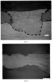
FIG. 1 is a view of an effect obtained after ultrasonic pre-welding in some scenarios. -
FIG. 2 is a view of an effect obtained after ultrasonic pre-welding in some scenarios. -
FIG. 3 is a schematic structural view of a vehicle according to an embodiment of the present disclosure. -
FIG. 4 is a schematic exploded view of a structure of a battery according to an embodiment of the present disclosure. -
FIG. 5 is a schematic exploded view of a structure of a battery cell according to an embodiment of the present disclosure. -
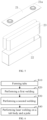
FIG. 6 is a flowchart illustrating a tab welding method according to an embodiment of the present disclosure. -
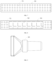
FIG. 7 is a schematic view obtained after first welding according to an embodiment of the present disclosure. -
FIG. 8 is a schematic view of a structure obtained after second welding according to an embodiment of the present disclosure. -
FIG. 9 is a schematic structural view of a toothless welding head according to an embodiment of the present disclosure. -
FIG. 10 is a schematic view of an effect obtained after ultrasonic pre-welding according to an embodiment of the present disclosure. -
FIG. 11 is a partially enlarged view forFIG. 10 . -
FIG. 12 is a schematic view of an effect obtained after laser welding according to an embodiment of the present disclosure. - 1000, vehicle; 100, battery; 200, controller; 300, motor; 10, case; 20, battery cell; 30, tab body; 40, toothless welding head; 11, first portion; 12, second portion; 21, end cover; 22, housing; 23, electrode assembly; 31, first weld spot region; 32, second weld spot region; 21a, electrode terminal.
- Embodiments of technical solutions of the present disclosure will be described in detail below with reference to the accompanying drawings. The following embodiments are only used to explain the technical solutions of the present disclosure more clearly, and therefore should be construed as examples only, rather than limitations of the protection scope of the present disclosure.
- Unless otherwise defined, all technical and scientific terms used herein have the same meaning as commonly understood by those skilled in the art of the present disclosure. Terms in the present disclosure herein are only used for the purpose of describing specific embodiments, and are not intended to limit the present disclosure. Terms "including", "having", and any variations thereof in the specification, claims, and accompanying drawings of the present disclosure are intended to cover non-exclusive inclusions.
- In the description of the embodiments of the present disclosure, the technical terms "first", "second", etc. are used to distinguish different objects, and cannot be understood as indicating or implying relative importance or implicitly specifying a number, a particular order, or a primary or secondary relationship of the indicated technical features. In the description of the embodiments of the present disclosure, "plurality" means at least two, unless otherwise specifically defined.
- In the present disclosure, reference to "embodiment" means that a particular feature, structure, or characteristic described in conjunction with the embodiment or implementation may be included in at least one embodiment of the present disclosure. The presence of the term at each place in the specification does not necessarily refer to the same embodiment, nor does it refer to a separate or alternative embodiment that is mutually exclusive of other embodiments. It should be understood by those skilled in the art, both explicitly and implicitly, that the embodiments described herein may be combined with other embodiments.
- In the description of the embodiments of the present disclosure, the term "and/or" only represents a relationship between correlated objects, including three relationships. For example, "A and/or B" may mean three situations: A only, B only, or both A and B. In addition, the character "/" in the present disclosure generally represents an "or" relationship between the correlated objects preceding and succeeding the symbol.
- In the description of the embodiments of the present disclosure, the term "plurality" refers to more than two (including two). Similarly, "plurality of groups" refers to more than two groups (including two groups), and "plurality of pieces" refers to more than two pieces (including two pieces).
- In the description of the embodiments of the present disclosure, the orientation or the position indicated by technical terms such as "center", "longitudinal", "lateral", "length", "width", "thickness", "over", "below", "front", "rear", "left", "right", "vertical", "horizontal", "top", "bottom", "inner", "outer", "clockwise", "anti-clockwise", "axial", "radial", and "circumferential" should be construed to refer to the orientation and the position as shown in the drawings, and is only for the convenience of describing the embodiments of the present disclosure and simplifying the description, rather than indicating or implying that the pointed device or element must have a specific orientation, or be constructed and operated in a specific orientation, and therefore cannot be understood as a limitation of the embodiments of the present disclosure.
- In the description of the embodiments of the present disclosure, unless otherwise clearly specified and limited, technical terms such as "install", "connect", "connect to", "fix" and the like should be understood in a broad sense. For example, it may be a fixed connection or a detachable connection or connection as one piece; mechanical connection or electrical connection; direct connection or indirect connection through an intermediate; internal communication of two components or the interaction relationship between two components. For those skilled in the art, the specific meaning of the above-mentioned terms in the embodiments of the present disclosure can be understood according to specific circumstances.
- At present, from the perspective of the development of the market, lithium-ion batteries are widely applied in electric vehicles and consumer electronic products due to their advantages such as high energy density, high output power, long cycle life, and low environmental pollution. With a continuous expansion of the application field of the lithium-ion batteries, a market demand for the lithium-ion batteries is also increasing.
- A manufacturing process of the lithium-ion batteries usually includes: step 1 of preparing electrode slurry, mainly including mixing an electrode active substance, a binder, a solvent, etc., with each other, and then fully stirring and dispersing them to form a slurry; step 2 of coating, comprising uniformly coating the slurry prepared in step 1 onto a current collector (aluminum foil, copper foil, or the like) with a specified thickness, and the solvent is dried; step 3 of punching and cutting of electrode sheets, including punching each of the electrode sheets made in the previous step and cutting into a specified size and a specified shape; step 4 of stacking, including assembling and gluing positive electrode sheets, negative electrode sheets, and separators together, to form a pole core; and step 5 of assembling a hard-shell battery cell, including loading the pole core manufactured in the previous step into the punched shell and completing top sealing, side sealing, etc. (with a liquid injection opening reserved) to form the hard-shell battery cell injected with no liquid; step 6 of injecting liquid, including injecting a specified amount of electrolyte into the hard-shell battery cell; and step 7 of sealing a battery, including extracting a gas in the battery cell in a vacuum environment, and sealing the battery cell.
- During the stacking described above, after a plurality of layers of positive electrode sheets is stacked to each other, active substances on the positive electrode sheets form positive poles and inactive substances on the positive electrode sheets form positive tabs. Similarly, after a plurality of layers of negative electrode sheets is stacked to each other, active substances on the negative electrode sheets form negative poles and inactive substances on the negative electrode sheets form negative tabs. The positive tabs and the negative tabs need to be stacked to each other and then welded together, and subsequently fixed to the poles through welding again.
- At present, typically, ultrasonic pre-welding is performed on the plurality of stacked layers of the positive and negative tabs, and then a plurality of layers of pre-welded tabs is fixed to poles through laser welding. The ultrasonic pre-welding is performed, using a toothed welding head, on the plurality of stacked layers of the positive and negative tabs. After a long period of observation, it was noticed that, if pre-welding is performed with the above-mentioned method, a fusion region will easily crack during subsequent laser welding of a finished tab on which welding is completed (i.e., an entirety formed by the positive and negative tabs subjected to two times of ultrasonic welding, which will be collectively referred to as the finished tab for simplicity) to the poles, affecting a current flow capacity and structural strength.
- After the above problems were discovered, a large number of experiments and analyses were conducted, and the following reasons that may lead to the above problems are identified.
- The interlayer gaps exist in the finished tab that has been subjected to pre-welding of the toothed welding head. When laser welding is performed on the finished tab and the poles subsequently, the interlayer gaps will generate a large number of pores during the laser welding, and a large amount of heat buildup leads to cracks in the fusion region. The large number of pores will reduce an effective connection region, affecting the current flow capacity.
- As illustrated in
FIG. 1 and FIG. 2 , specifically, in some cases, for the battery cell, ultrasonic pre-welding is performed on the positive tabs and the negative tabs, which, along with a welding technique that the finished tab is fixed to the poles through the laser welding, results in cracks on both sides of laser weld seams between the finished tab and the poles, affecting the current flow capacity and the structural strength. Further, pores and gaps are generated in the finished tab during the laser welding, which reduce the effective connection region, affecting the current flow capacity. - In addition, further experiments and verifications were conducted on a material of the battery cell. The battery cell is made of aluminum foil. Some physical properties of the aluminum foil are compared with those of the copper foil. Results of the comparison are as illustrated in Table 1, which shows the comparison between some physical properties of the aluminum foil and those of the copper foil.
Table 1 / Material Melting point Coefficient of thermal conductivity Expansion coefficient Copper foil Pure copper 1,083 °C 397 W/m*k 1.75×10⁻⁵/k Aluminum foil Al 1060 667 °C 217 W/m*k 2.23×10⁻⁵/k - Table 1 reveals that a high shrinkage ratio of the metal aluminum during solidification leads to necking of a liquid metal in a welding pool interface for tabs. Pores are generated in the interlayer gaps when the tabs are welded. However, the interlayer gaps cause the liquid metal, when subjected to the necking, to fail to fill in when welded to the pole, resulting in cracks in the weld seams.
- Therefore, it was found that, the interlayer gaps in the positive and negative tabs that have been subjected to the pre-welding need to be eliminated to improve welding performance between the finished tab and the poles. To eliminate the interlayer gaps, a scheme of ultrasonic pre-welding needs to be optimized and improved.
- Based on the above considerations, to reduce cracks generated when the finished tab is welded to the poles, and to solve the problem that the interlayer gaps are easily generated during the per-welding on the plurality of layers of tabs, a tab welding method is designed after an in-depth study. In the tab welding method, a special pre-welding scheme combining a toothed welding head and a toothless welding head is adopted to allow the plurality of stacked layers of the positive and negative tabs to form a compact overall structure after two times of ultrasonic welding, which eliminates the interlayer gaps, solving problems of welding pores and cracks in the fusion region that arise during the laser welding performed on the finished tab and the poles.
- The battery cell disclosed in the embodiments of the present disclosure may be, but is not limited to being, applied in an electric device such as a vehicle, a ship, or an aircraft.
- In the following embodiments, as an example, an electric device according to an embodiment of the present disclosure is described as a
vehicle 1000 for convenience of description. -
FIG. 3 is a schematic structural view of avehicle 1000 according to an embodiment of the present disclosure. Referring toFIG. 3 , abattery 100 is disposed in thevehicle 1000. Thebattery 100 may be disposed at a bottom or a head or a tail of thevehicle 1000, and can be configured to supply power to thevehicle 1000. For example, thebattery 100 may be used as a power source for operation of thevehicle 1000. Thevehicle 1000 may further include acontroller 200 and amotor 300. Thecontroller 200 is configured to control thebattery 100 to supply power to themotor 300, e.g., for operational power needs in starting, navigation, and traveling of thevehicle 1000. - In some embodiments of the present disclosure, the
battery 100 may not only serve as the power source for operation of thevehicle 1000, but also serve as a drive power source for thevehicle 1000 in lieu of, or in part in lieu of a fuel oil or a natural gas to provide drive power for thevehicle 1000. -
FIG. 4 is an exploded view of thebattery 100 according to some embodiments of the present disclosure. Referring toFIG. 4 , thebattery 100 includes acase 10 and abattery cell 20. Thebattery cell 20 is accommodated in thecase 10. Thecase 10 is configured to provide an accommodation space for thebattery cell 20 and may be of various structures. In some embodiments, thecase 10 may include afirst portion 11 and asecond portion 12 that are capped on each other. The accommodation space for accommodating thebattery cell 20 is defined by thefirst portion 11 and thesecond portion 12 together. Thesecond portion 12 may have a hollow structure with an open end while thefirst portion 11 may have a plate-like structure. Thefirst portion 11 is capped at an open side of thesecond portion 12 to define the accommodation space by thefirst portion 11 and thesecond portion 12 together. Each of thefirst portion 11 and thesecond portion 12 may also have a hollow structure with an open side. The open side of thefirst portion 11 is capped at the open side of thesecond portion 12. Of course, thecase 10 formed by thefirst portion 11 and thesecond portion 12 may be of various shapes, such as a cylinder and a cuboid. - In the
battery 100, a plurality ofbattery cells 20 may be provided. The plurality ofbattery cells 20 may be connected in series or in parallel or in series and parallel. The expression "in series and parallel" means that the plurality ofbattery cells 20 is connected both in series and in parallel. The plurality ofbattery cells 20 may be directly connected in series or in parallel or in series and parallel, and then accommodated in thecase 10 as a whole. Of course, for thebattery 100, the plurality ofbattery cells 20 may also be connected in series or in parallel or in series and parallel to form a battery module, and then a plurality of battery modules may be connected in series or in parallel or in series and parallel and accommodated in thecase 10 as a whole. Thebattery 100 may further have other structures. For example, thebattery 100 may further include a busbar configured to implement an electrical connection between the plurality ofbattery cells 20. - Each
battery cell 20 may be a rechargeable battery or a primary battery. The battery cell may further be a lithium-sulfur battery, a sodium-ion battery, or a magnesium-ion battery. The present disclosure is not limited to any of these examples. -
FIG. 5 is a schematic exploded view of a structure of thebattery cell 20 according to some embodiments of the present disclosure. Thebattery cell 20 is the smallest unit that makes up a battery. Referring toFIG. 5 , thebattery cell 20 includes anend cover 21, ahousing 22, abattery cell assembly 23, and other functional members. - The
end cover 21 is a member that covers an opening of thehousing 22 to isolate an internal environment of thebattery cell 20 from an external environment. Without limitation, a shape of theend cover 21 may be adapted to a shape of thehousing 22 to cooperate with thehousing 22. Optionally, theend cover 21 may be made of a material having a predetermined degree of hardness and strength (e.g., an aluminum alloy). In this way, theend cover 21 is less likely to deform when subjected to a compression and a collision, enabling thebattery cell 20 to have higher structural strength and improved safety performance. Functional members such as anelectrode terminal 21a may be disposed at theend cover 21. Theelectrode terminal 21a can be configured to be electrically connected to thebattery cell assembly 23 to output or input electric energy of thebattery cell 20. In some embodiments, a pressure relief mechanism may further be disposed at theend cover 21. The pressure relief mechanism is configured to release an internal pressure of thebattery cell 20 when the internal pressure or a temperature of thebattery cell 20 reaches a threshold. Theend cover 21 may be made of a variety of materials, such as copper, iron, aluminum, stainless steel, aluminum alloy, and plastic. The embodiments of the present disclosure are not specifically limited to any of these examples. In some embodiments, an insulator may also be disposed at an inner side of theend cover 21. The insulator can be configured to isolate an electrical connector in thehousing 22 from theend cover 21, to reduce a short-circuit risk. For example, the insulator may be made of plastic, rubber, or the like. - The
housing 22 is an assembly configured to cooperate with theend cover 21 to form the internal environment of thebattery cell 20. The formed internal environment can be configured to accommodate thebattery cell assembly 23, the electrolyte, and other members. Thehousing 22 and theend cover 21 may be independent members. An opening may be formed at thehousing 22. The internal environment of thebattery cell 20 may be formed by covering the opening with theend cover 21. Without limitation, theend cover 21 and thehousing 22 may also be integrally formed. Specifically, a common connection surface may be formed by theend cover 21 and thehousing 22 before other members are put into the housing. Theend cover 21 is made to cover thehousing 22 when it is necessary to package an interior of thehousing 22. Thehousing 22 may have various shapes and various dimensions, such as a cuboid shape, a cylinder shape, and a hexagonal prism shape. Specifically, the shape of thehousing 22 may be determined based on a specific shape and a specific dimension size of theelectrode assembly 23. Thehousing 22 may be made of various materials, such as copper, iron, aluminum, stainless steel, aluminum alloy, and plastic. The embodiments of the present disclosure are not specially limited to any of these examples. - The
electrode assembly 23 is a member, in thebattery cell 20, where an electrochemical reaction occurs. One ormore electrode assemblies 23 may be included in thehousing 22. Theelectrode assembly 23 is formed primarily by winding or stacking a positive electrode sheet and a negative electrode sheet. Typically, a separator is located between the positive electrode sheet and the negative electrode sheet. Parts of the positive electrode sheet and the negative electrode sheet that contain active substances form a main body portion of theelectrode assembly 23. Parts of the positive electrode sheet and the negative electrode sheet that contain no active substances each form a tab. A positive tab and a negative tab may be both located at one end of the main body portion, or may be located at two ends of themain body portion 100, respectively. During charging and discharging of the battery, positive active substances and negative active substances are reacted with the electrolyte. The tab is connected to theelectrode terminal 21a to form a current circuit. - Referring to
FIG. 6 ,FIG. 7, and FIG. 8 , a tab welding method is provided according to an embodiment of the present disclosure. The tab welding method includes the steps S10, S20, S30, and S40. - In step S10 of forming tabs, including forming a plurality of stacked layers of positive tabs and negative tabs by sequentially stacking a plurality of layers of positive electrode sheets and a plurality of layers of negative electrode sheets.
- In step S20 of performing a first welding, including performing welding on the plurality of stacked layers of positive tabs and negative tabs using a toothed welding head (not illustrated in the figures), to form a
tab body 30 having a first weld spot region 31. - The toothed welding head used for the first welding has a size of 5 millimeters (mm)×30 millimeters (mm), and thus the first weld spot region 31 formed through welding by the toothed welding head has an area of 5 mm×30 mm. Further, the toothed welding head has a weld tooth height of 0.45 mm. In addition, the toothed welding head is a spherical-tooth welding head having a weld tooth radius of 0.8 mm and a weld tooth pitch of 0.32 mm. After welding of the toothed welding head, the uneven first weld spot region 31 is formed, enabling a solid-phase connection for the
tab body 30. - In step S30 of performing a second welding, including performing the second welding on the
tab body 30 using atoothless welding head 40, to form a second weld spot region 32. - As illustrated in
FIG. 9 , it should be noted that thetoothless welding head 40 has a welding surface formed as a smooth surface. Thus, the uneven first weld spot region 31 is shaped and flattened by thetoothless welding head 40, which avoids a slip during ultrasonic vibrations, and eliminates gaps of the plurality of stacked layers of the positive tabs and the negative tabs of thetab body 30. - In some embodiments, the
toothless welding head 40 has a size of 4 mm×20 mm. Thus, the second weld spot region 32 formed through welding by thetoothless welding head 40 has an area of 4 mm×20 mm, in such a manner that the second weld spot region 32 is located in the first weld spot region 31. Further, the second weld spot region 32 is smaller than the first weld spot region 31. In addition, the first weld spot region 31 has a center point coinciding with a center point of the second weld spot region 32. - In some embodiments, each of the first welding and the second welding is ultrasonic welding.
- Specifically, since the ultrasonic pre-welding is performed, by the high toothed welding head, on the plurality of stacked layers of the positive tabs and the negative tabs during the first welding, the solid-phase connection is realized between the plurality of stacked layers of the positive tabs and the negative tabs. Compared with a flat-tooth welding head, the toothed welding head has higher strength, and thus a welding part is less likely to be broken apart by ultrasonic vibrations during the second welding. Regarding the second welding, the
toothless welding head 40 is used for the ultrasonic vibrations. In addition, since the second weld spot region 32 is smaller than the first weld spot region 31 and located above the first weld spot region 31, a slip caused when thetoothless welding head 40 performs welding on a smooth surface can be avoided, and thus the uneven part can be shaped and flattened, eliminating the interlayer gaps. - In some embodiments, the
toothless welding head 40 has an arc chamfer with a radius of 1 mm. With the arc chamfer, the welding head can be in close contact with a weld spot region during welding, which improves welding performance. - Step S40, the
tab body 30 subjected to two times of welding is fixedly connected to a pole through laser welding. - After two times of ultrasonic pre-welding were performed based on data shown in Table 2 below, laser welding was performed and results shown in Table 3 below were obtained. Table 2 shows parameter values for the two times of ultrasonic pre-welding. Table 3 shows parameter results for the laser welding.
Table 2 Ultrasonic pre-welding window for tabs Ultrasonic welding Energy J Atmospheric pressure/Psi Amplitude um Welding head specification mm Tooth height mm Tooth profile first time 500 40 30 5×30 0.45 Spherical second time 200 25 30 4×20 0 Toothless Table 3 Laser welding window Power/w Linear velocity/(mm/s) Defocusing amount/mm Weld seam length/mm 2,500 50 -4 15 - From Table 2 and Table 3, it can be concluded that after welding is performed, using the above-mentioned tab welding method, on the plurality of stacked layers of the positive tabs and the negative tabs, no pores or cracks present between the plurality of stacked layers of the positive tabs and negative tabs, as illustrated in
FIG. 10 and FIG. 11 . In addition, for thetab body 30 subjected to the two times of ultrasonic pre-welding and the pole subjected to the laser welding, similarly, no pores or cracks present, as illustrated inFIG. 12 . Thus, with the above-mentioned tab welding method, the interlayer gap and pores can be effectively eliminated, solving a problem that cracks are likely to occur when welding the tabs to the poles. - Based on the same concept as the above-mentioned tab welding method, the present disclosure further provides a tab welding tool for performing the above-mentioned tab welding method. The tab welding tool includes the
toothless welding head 40 and the toothed welding head (not illustrated in the figures). The toothed welding head has the weld tooth height of 0.45 mm. In addition, the toothed welding head is the spherical-tooth welding head having the weld tooth radius of 0.8 mm and the weld tooth pitch of 0.32 mm. Thetoothless welding head 40 has a welding surface formed as a smooth surface. Thus, the uneven region obtained after the first welding is shaped and flattened by thetoothless welding head 40, which avoids a slip during ultrasonic vibrations, and eliminates gaps of the plurality of stacked layers of the tabs of thetab body 30. - In some embodiments, the toothed welding head having a welding region formed as the first weld spot region 31, and the
toothless welding head 40 having a welding region formed as the second weld spot region 32. The second weld spot region 32 is smaller than the first weld spot region 31. The first weld spot region 31 has a center point coinciding with a center point of the second weld spot region 32. - In some embodiments, the
toothless welding head 40 has the size of 4 mm×20 mm, while the toothed welding head has the size of 5 mm×30 mm. Thus, the first weld spot region 31 formed through welding by the toothed welding head has an area of 5 mm×30 mm, and the second weld spot region 32 formed through welding by thetoothless welding head 40 has an area of 4 mm×20 mm, in such a manner that the second weld spot region 32 is located within the first weld spot region 31. - Since the welding is performed, by the high toothed welding head, on the plurality of stacked layers of the positive tabs and the negative tabs during the first welding, a solid-phase connection is realized between the plurality of stacked layers of the positive tabs and the negative tabs. Compared with the flat-tooth welding head, the toothed welding head has higher strength, and thus the welding part is less likely to be broken apart by the ultrasonic vibrations during the second welding. Regarding the second welding, the
toothless welding head 40 is used for the ultrasonic vibrations. In addition, since the second weld spot region 32 is smaller than the first weld spot region 31 and located above the first weld spot region 31, a slip caused when thetoothless welding head 40 performs welding on the smooth surface can be avoided, and thus the uneven part can be shaped and flattened, eliminating the interlayer gaps. - In some embodiments, the
toothless welding head 40 has the arc chamfer with the radius of 1 mm. With the arc chamfer, the welding head can be in close contact with the weld spot region during welding, which improves the welding performance. - Based on the same concept as the above-mentioned tab welding method, the present disclosure further provides a battery cell prepared by the above-mentioned tab welding method.
- Based on the same concept as the above-mentioned battery cell, the present disclosure further provides a battery. The battery includes a housing and the above-mentioned battery cell. The battery cell is disposed in the housing.
- Based on the same concept as the above-mentioned battery, the present disclosure further provides an electric device. The electric device includes an electrical body and the above-mentioned battery.
- In the practice of the present disclosure, the plurality of layers of positive electrode sheets and the plurality of layers of negative electrode sheets are stacked to each other separately, to form the plurality of stacked layers of positive tabs and negative tabs. Subsequently, the ultrasonic welding is performed, using the toothed welding head, on the plurality of stacked layers of positive tabs and negative tabs, to form the
tab body 30 having the first weld spot region 31. Further, the ultrasonic welding is performed on thetab body 30 using the smoothtoothless welding head 40 to form the second weld spot region 32. In addition, the second weld spot region 32 is made to be located within the first weld spot region 31, in such a manner that the center point of the first weld spot region 31 coincides with the center point of the second weld spot region 32. - After the two times of ultrasonic welding are performed on the plurality of stacked layers of the positive tabs and the negative tabs, the
pre-welded tab body 30 is fixedly connected to the poles through laser welding. Thus, the entire welding process is completed. - The tab welding method, the welding tool, the battery cell, the battery, and the electric device in the above embodiments can provide at least the following advantages.
- First, the uneven welding surface formed through the welding by the toothed welding head can be shaped and flattened by the
toothless welding head 40, which can avoid a slip of thetoothless welding head 40 during performing welding on a smooth surface, eliminating interlayer gaps to solve a cracking problem. - Second, the arc chamfer having the radius of 1 mm disposed at the
toothless welding head 40 can enable the welding head to be in close contact with the weld spot region during welding, which improves the welding performance. - Third, the
toothless welding head 40 has a simple structure and is easy to operate, which is conducive to promotion of thetoothless welding head 40. - Finally, it should be noted that each of the above embodiments is used only to illustrate, rather than to limit, the technical solutions of the present disclosure. Although the present disclosure has been described in detail with reference to the foregoing embodiments, it is conceivable for those skilled in the art that modifications can be made to the technical solutions described in the foregoing embodiments, or equivalent replacements can be made to some or all of the technical features in the technical solutions described in the foregoing embodiments. These modifications or equivalent replacements, which do not depart the essence of corresponding technical solutions from the scope of the technical solutions of the embodiments of the present disclosure, shall fall within the scope of the claims and the specification of the present disclosure. In particular, the technical features mentioned in individual embodiments can be combined arbitrarily without any structural conflict. The present disclosure is not limited to the particular embodiments disclosed herein, and includes all technical solutions falling within the scope of the claims.
Claims (19)
- A tab welding method, comprising:step S10 of forming tabs, comprising forming a plurality of stacked layers of positive tabs and negative tabs by sequentially stacking a plurality of layers of positive electrode sheets and a plurality of layers of negative electrode sheets;step S20 of performing a first welding, comprising performing welding on the plurality of stacked layers of positive tabs and negative tabs using a toothed welding head, to form a tab body having a first weld spot region; andstep of S30 of performing a second welding, comprising performing the second welding on the tab body using a toothless welding head, to form a second weld spot region.
- The tab welding method according to claim 1, wherein in step S20, the toothed welding head has a size of 5 mm×30 mm.
- The tab welding method according to claim 1 or 2, wherein in step S20, the toothed welding head has a weld tooth height of 0.45 mm.
- The tab welding method according to any one of claims 1 to 3, wherein in step S20, the toothed welding head has a weld tooth radius of 0.8 mm and a weld tooth pitch of 0.32 mm.
- The tab welding method according to any one of claims 1 to 4, wherein in step S30, the toothless welding head has a welding surface formed as a smooth surface.
- The tab welding method according to any one of claims 1 to 5, wherein in step S30, the toothless welding head has a size of 4 mm×20 mm.
- The tab welding method according to claim 5 or 6, wherein the toothless welding head has an arc chamfer with a radius of 1 mm.
- The tab welding method according to any one of claims 1 to 7, wherein:the second weld spot region is smaller than the first weld spot region; andthe first weld spot region has a center point coinciding with a center point of the second weld spot region.
- The tab welding method according to any one of claims 1 to 8, wherein each of the first welding and the second welding is ultrasonic welding.
- A tab welding tool for performing the tab welding method according to any one of claims 1 to 9, the tab welding tool comprising the toothless welding head, the toothless welding head having a welding surface formed as a smooth surface.
- The tab welding tool according to claim 10, wherein the toothless welding head has a size of 4 mm×20 mm.
- The tab welding tool according to claim 10 or 11, wherein the toothless welding head has an arc chamfer with a radius of 1 mm.
- The tab welding tool according to any one of claims 10 to 12, comprising the toothed welding head, the toothed welding head having a welding region formed as the first weld spot region, and the toothless welding head having a welding region formed as the second weld spot region, wherein:the second weld spot region is smaller than the first weld spot region; andthe first weld spot region has a center point coinciding with a center point of the second weld spot region.
- The tab welding tool according to claim 13, wherein the toothed welding head has a size of 5 mm×30 mm.
- The tab welding tool according to claim 13 or 14, wherein the toothed welding head has a weld tooth height of 0.45 mm.
- The tab welding tool according to any one of claims 13 to 15, wherein the toothed welding head has a weld tooth radius of 0.8 mm and a weld tooth pitch of 0.32 mm.
- A battery cell, the battery cell being prepared by the tab welding method according to any one of claims 1 to 9.
- A battery, comprising:a housing; andthe battery cell according to claim 17, the battery cell being disposed in the housing.
- An electric device, comprising:an electrical body; andthe battery according to claim 18.
Applications Claiming Priority (2)
| Application Number | Priority Date | Filing Date | Title |
|---|---|---|---|
| CN202111318931.2A CN115837510B (en) | 2021-11-09 | 2021-11-09 | Lug welding method, welding tool, battery cell, battery and electricity utilization device |
| PCT/CN2022/127902 WO2023083011A1 (en) | 2021-11-09 | 2022-10-27 | Tab welding method, welding tool, battery cell, battery, and electric device |
Publications (2)
| Publication Number | Publication Date |
|---|---|
| EP4382237A1 true EP4382237A1 (en) | 2024-06-12 |
| EP4382237A4 EP4382237A4 (en) | 2025-05-07 |
Family
ID=85574605
Family Applications (1)
| Application Number | Title | Priority Date | Filing Date |
|---|---|---|---|
| EP22891807.4A Pending EP4382237A4 (en) | 2021-11-09 | 2022-10-27 | TAB WELDING METHOD, WELDING TOOL, BATTERY CELL, BATTERY AND ELECTRICAL DEVICE |
Country Status (4)
| Country | Link |
|---|---|
| US (1) | US20240170809A1 (en) |
| EP (1) | EP4382237A4 (en) |
| CN (1) | CN115837510B (en) |
| WO (1) | WO2023083011A1 (en) |
Families Citing this family (3)
| Publication number | Priority date | Publication date | Assignee | Title |
|---|---|---|---|---|
| CN116598561B (en) * | 2023-05-09 | 2024-04-16 | 深圳欣界能源科技有限公司 | A packaging method for laminated battery core and laminated battery |
| CN116586851B (en) * | 2023-07-17 | 2023-11-21 | 宁德时代新能源科技股份有限公司 | Structural member, manufacturing method thereof, battery monomer, battery and electric equipment |
| CN118589159B (en) * | 2024-08-06 | 2024-12-20 | 宁德时代新能源科技股份有限公司 | Battery cell, battery, power utilization device, welding device and welding method |
Family Cites Families (17)
| Publication number | Priority date | Publication date | Assignee | Title |
|---|---|---|---|---|
| CN102513686A (en) * | 2011-12-02 | 2012-06-27 | 苏州冠硕新能源有限公司 | Ultrasonic welding head, ultrasonic welding equipment provided with same and method for welding battery poles by utilizing ultrasonic welding equipment |
| WO2013105361A1 (en) * | 2012-01-12 | 2013-07-18 | 日立マクセル株式会社 | Ultrasonic welding tip, ultrasonic welding machine, and method for producing battery |
| DE112012006588T5 (en) * | 2012-06-28 | 2015-04-02 | Toyota Jidosha Kabushiki Kaisha | Method for producing a battery and a battery |
| DE102012018912A1 (en) * | 2012-09-26 | 2013-03-21 | Daimler Ag | Preparing film stack, by forming film stack form a number of firmly bonded metal foils connected to each other, where the foils are arranged one above the other in a process step and compacted and prefixed by a high frequency ultrasound |
| JP2015199095A (en) * | 2014-04-08 | 2015-11-12 | 株式会社デンソー | Ultrasonic welding apparatus and method of manufacturing battery |
| KR102211524B1 (en) * | 2014-08-11 | 2021-02-02 | 삼성에스디아이 주식회사 | Ultrasonic welding device, rechargeable battery manufacturing method using the same, and rechargeable battery thereof |
| JP2016219274A (en) * | 2015-05-21 | 2016-12-22 | 株式会社豊田自動織機 | Method for manufacturing electrode assembly and electrode laminate |
| DE102018221843A1 (en) * | 2018-12-14 | 2020-06-18 | Volkswagen Aktiengesellschaft | Ultrasonic welding device and method for producing a metal foil stack |
| KR102323041B1 (en) * | 2019-02-01 | 2021-11-08 | 주식회사 엘지에너지솔루션 | Electrode Assembly Comprising Different Pressure Welded Part on Weld Surface of Electrode Tab and Ultrasonic Welding Device for Manufacturing the Same |
| JP7305367B2 (en) * | 2019-02-08 | 2023-07-10 | 三洋電機株式会社 | Electric storage element manufacturing method, electric storage element, joining method, and joined body |
| CN209786103U (en) * | 2019-06-11 | 2019-12-13 | 宁德时代新能源科技股份有限公司 | Secondary battery |
| CN110936010B (en) * | 2019-10-25 | 2021-12-14 | 合肥国轩高科动力能源有限公司 | A kind of lithium battery composite current collector tab welding method |
| CN211072230U (en) * | 2019-11-06 | 2020-07-24 | 恒大新能源技术(深圳)有限公司 | Utmost point ear subassembly and ultrasonic welding device thereof |
| CN111785903A (en) * | 2020-07-15 | 2020-10-16 | 中航锂电(洛阳)有限公司 | Battery and battery manufacturing method |
| CN112453735A (en) * | 2020-10-09 | 2021-03-09 | 湖北亿纬动力有限公司 | Tab welding method, battery manufacturing method and battery |
| CN112421188A (en) * | 2020-10-30 | 2021-02-26 | 蜂巢能源科技有限公司 | Welding method of tab and cover plate, battery module, battery pack and vehicle |
| CN113042874A (en) * | 2021-03-10 | 2021-06-29 | 昆山聚创新能源科技有限公司 | Ultrasonic welding head |
-
2021
- 2021-11-09 CN CN202111318931.2A patent/CN115837510B/en active Active
-
2022
- 2022-10-27 EP EP22891807.4A patent/EP4382237A4/en active Pending
- 2022-10-27 WO PCT/CN2022/127902 patent/WO2023083011A1/en not_active Ceased
-
2024
- 2024-01-31 US US18/428,727 patent/US20240170809A1/en active Pending
Also Published As
| Publication number | Publication date |
|---|---|
| CN115837510A (en) | 2023-03-24 |
| US20240170809A1 (en) | 2024-05-23 |
| EP4382237A4 (en) | 2025-05-07 |
| WO2023083011A1 (en) | 2023-05-19 |
| CN115837510B (en) | 2024-01-16 |
Similar Documents
| Publication | Publication Date | Title |
|---|---|---|
| EP4382237A1 (en) | Tab welding method, welding tool, battery cell, battery, and electric device | |
| JP4433650B2 (en) | Lithium secondary cell and connection structure of lithium secondary cell | |
| CN102918680B (en) | Battery and battery pack | |
| CN101779310B (en) | Battery | |
| CN102412380B (en) | Battery and ultrasonic bonding method for battery | |
| EP4293769A1 (en) | Battery cell, battery, and electric device | |
| JP4210961B1 (en) | Battery with battery case and sealing plate | |
| CN102460771B (en) | Sealed battery | |
| CN102005598A (en) | Rechargeable secondary battery having improved safety against puncture and collapse | |
| KR20190104685A (en) | Cylindrical Battery Having Structure Shielding Laser Beam for Welding and Battery Pack Comprising the Same | |
| JP7738589B2 (en) | Energy storage devices | |
| US10873068B2 (en) | Secondary battery and method for manufacturing the same | |
| JP5206242B2 (en) | Power storage device and method for manufacturing power storage device | |
| JP4713393B2 (en) | Secondary battery and method for manufacturing secondary battery | |
| US20240055737A1 (en) | Battery | |
| KR20240174489A (en) | Secondary battery and method of manufacturing same | |
| KR102722652B1 (en) | Battery and battery case included in battery, and battery case member for building battery case | |
| KR102108208B1 (en) | Cylindrical Secondary Battery Having Circular Electrode | |
| KR102898369B1 (en) | Lithium ion secondary battery and method of manufacturing the same | |
| WO2024148474A1 (en) | Electrode sheet of battery, electrode assembly, battery cell, battery, and electric device | |
| JP2024011384A (en) | battery | |
| CN221538609U (en) | Welding device, battery cell, battery and electricity utilization device | |
| KR20150005362A (en) | Welded Construction For Easy Gas Emission And Battery Module Comprising the Same | |
| KR101867650B1 (en) | Battery Cell Employed with Battery Case Having Depressed Groove | |
| CN220382281U (en) | An electrode assembly, battery cell, battery and electrical device |
Legal Events
| Date | Code | Title | Description |
|---|---|---|---|
| STAA | Information on the status of an ep patent application or granted ep patent |
Free format text: STATUS: THE INTERNATIONAL PUBLICATION HAS BEEN MADE |
|
| PUAI | Public reference made under article 153(3) epc to a published international application that has entered the european phase |
Free format text: ORIGINAL CODE: 0009012 |
|
| STAA | Information on the status of an ep patent application or granted ep patent |
Free format text: STATUS: REQUEST FOR EXAMINATION WAS MADE |
|
| 17P | Request for examination filed |
Effective date: 20240306 |
|
| AK | Designated contracting states |
Kind code of ref document: A1 Designated state(s): AL AT BE BG CH CY CZ DE DK EE ES FI FR GB GR HR HU IE IS IT LI LT LU LV MC ME MK MT NL NO PL PT RO RS SE SI SK SM TR |
|
| RAP1 | Party data changed (applicant data changed or rights of an application transferred) |
Owner name: CONTEMPORARY AMPEREX TECHNOLOGY(HONG KONG) LIMITED |
|
| DAV | Request for validation of the european patent (deleted) | ||
| DAX | Request for extension of the european patent (deleted) | ||
| A4 | Supplementary search report drawn up and despatched |
Effective date: 20250407 |
|
| RIC1 | Information provided on ipc code assigned before grant |
Ipc: H01M 4/139 20100101ALI20250401BHEP Ipc: H01M 50/538 20210101ALI20250401BHEP Ipc: H01M 50/536 20210101ALI20250401BHEP Ipc: H01M 10/058 20100101ALI20250401BHEP Ipc: B23K 28/02 20140101ALI20250401BHEP Ipc: B23K 20/10 20060101AFI20250401BHEP |