EP4382225A1 - Fastener delivery system - Google Patents
Fastener delivery system Download PDFInfo
- Publication number
- EP4382225A1 EP4382225A1 EP23214128.3A EP23214128A EP4382225A1 EP 4382225 A1 EP4382225 A1 EP 4382225A1 EP 23214128 A EP23214128 A EP 23214128A EP 4382225 A1 EP4382225 A1 EP 4382225A1
- Authority
- EP
- European Patent Office
- Prior art keywords
- fastener
- delivery system
- chamber assembly
- storage cassette
- selection chamber
- Prior art date
- Legal status (The legal status is an assumption and is not a legal conclusion. Google has not performed a legal analysis and makes no representation as to the accuracy of the status listed.)
- Pending
Links
- 238000007689 inspection Methods 0.000 claims abstract description 13
- 239000012636 effector Substances 0.000 claims abstract description 12
- 238000000034 method Methods 0.000 description 9
- 230000000903 blocking effect Effects 0.000 description 6
- 238000013500 data storage Methods 0.000 description 3
- 230000005484 gravity Effects 0.000 description 2
- 238000007726 management method Methods 0.000 description 2
- 230000003287 optical effect Effects 0.000 description 2
- 230000006978 adaptation Effects 0.000 description 1
- 230000006870 function Effects 0.000 description 1
- 238000012986 modification Methods 0.000 description 1
- 230000004048 modification Effects 0.000 description 1
- 239000004065 semiconductor Substances 0.000 description 1
- 238000006467 substitution reaction Methods 0.000 description 1
Images



Classifications
-
- B—PERFORMING OPERATIONS; TRANSPORTING
- B21—MECHANICAL METAL-WORKING WITHOUT ESSENTIALLY REMOVING MATERIAL; PUNCHING METAL
- B21J—FORGING; HAMMERING; PRESSING METAL; RIVETING; FORGE FURNACES
- B21J15/00—Riveting
- B21J15/10—Riveting machines
- B21J15/30—Particular elements, e.g. supports; Suspension equipment specially adapted for portable riveters
- B21J15/32—Devices for inserting or holding rivets in position with or without feeding arrangements
-
- B—PERFORMING OPERATIONS; TRANSPORTING
- B65—CONVEYING; PACKING; STORING; HANDLING THIN OR FILAMENTARY MATERIAL
- B65G—TRANSPORT OR STORAGE DEVICES, e.g. CONVEYORS FOR LOADING OR TIPPING, SHOP CONVEYOR SYSTEMS OR PNEUMATIC TUBE CONVEYORS
- B65G47/00—Article or material-handling devices associated with conveyors; Methods employing such devices
- B65G47/02—Devices for feeding articles or materials to conveyors
- B65G47/04—Devices for feeding articles or materials to conveyors for feeding articles
- B65G47/12—Devices for feeding articles or materials to conveyors for feeding articles from disorderly-arranged article piles or from loose assemblages of articles
- B65G47/14—Devices for feeding articles or materials to conveyors for feeding articles from disorderly-arranged article piles or from loose assemblages of articles arranging or orientating the articles by mechanical or pneumatic means during feeding
- B65G47/1407—Devices for feeding articles or materials to conveyors for feeding articles from disorderly-arranged article piles or from loose assemblages of articles arranging or orientating the articles by mechanical or pneumatic means during feeding the articles being fed from a container, e.g. a bowl
-
- B—PERFORMING OPERATIONS; TRANSPORTING
- B23—MACHINE TOOLS; METAL-WORKING NOT OTHERWISE PROVIDED FOR
- B23P—METAL-WORKING NOT OTHERWISE PROVIDED FOR; COMBINED OPERATIONS; UNIVERSAL MACHINE TOOLS
- B23P19/00—Machines for simply fitting together or separating metal parts or objects, or metal and non-metal parts, whether or not involving some deformation; Tools or devices therefor so far as not provided for in other classes
- B23P19/001—Article feeders for assembling machines
-
- B—PERFORMING OPERATIONS; TRANSPORTING
- B25—HAND TOOLS; PORTABLE POWER-DRIVEN TOOLS; MANIPULATORS
- B25J—MANIPULATORS; CHAMBERS PROVIDED WITH MANIPULATION DEVICES
- B25J15/00—Gripping heads and other end effectors
- B25J15/0019—End effectors other than grippers
-
- B—PERFORMING OPERATIONS; TRANSPORTING
- B65—CONVEYING; PACKING; STORING; HANDLING THIN OR FILAMENTARY MATERIAL
- B65G—TRANSPORT OR STORAGE DEVICES, e.g. CONVEYORS FOR LOADING OR TIPPING, SHOP CONVEYOR SYSTEMS OR PNEUMATIC TUBE CONVEYORS
- B65G47/00—Article or material-handling devices associated with conveyors; Methods employing such devices
- B65G47/74—Feeding, transfer, or discharging devices of particular kinds or types
- B65G47/88—Separating or stopping elements, e.g. fingers
- B65G47/8807—Separating or stopping elements, e.g. fingers with one stop
- B65G47/8815—Reciprocating stop, moving up or down in the path of the article
-
- B—PERFORMING OPERATIONS; TRANSPORTING
- B65—CONVEYING; PACKING; STORING; HANDLING THIN OR FILAMENTARY MATERIAL
- B65G—TRANSPORT OR STORAGE DEVICES, e.g. CONVEYORS FOR LOADING OR TIPPING, SHOP CONVEYOR SYSTEMS OR PNEUMATIC TUBE CONVEYORS
- B65G51/00—Conveying articles through pipes or tubes by fluid flow or pressure; Conveying articles over a flat surface, e.g. the base of a trough, by jets located in the surface
- B65G51/02—Directly conveying the articles, e.g. slips, sheets, stockings, containers or workpieces, by flowing gases
-
- B—PERFORMING OPERATIONS; TRANSPORTING
- B21—MECHANICAL METAL-WORKING WITHOUT ESSENTIALLY REMOVING MATERIAL; PUNCHING METAL
- B21J—FORGING; HAMMERING; PRESSING METAL; RIVETING; FORGE FURNACES
- B21J15/00—Riveting
- B21J15/10—Riveting machines
- B21J15/14—Riveting machines specially adapted for riveting specific articles, e.g. brake lining machines
- B21J15/142—Aerospace structures
-
- B—PERFORMING OPERATIONS; TRANSPORTING
- B23—MACHINE TOOLS; METAL-WORKING NOT OTHERWISE PROVIDED FOR
- B23P—METAL-WORKING NOT OTHERWISE PROVIDED FOR; COMBINED OPERATIONS; UNIVERSAL MACHINE TOOLS
- B23P19/00—Machines for simply fitting together or separating metal parts or objects, or metal and non-metal parts, whether or not involving some deformation; Tools or devices therefor so far as not provided for in other classes
- B23P19/001—Article feeders for assembling machines
- B23P19/004—Feeding the articles from hoppers to machines or dispensers
Definitions
- the present invention relates to fastening systems, and more particularly to an automated fastener delivery system.
- Automated fastener delivery systems are known for use with robotic assembly systems in which individual fasteners are delivered or made available to an end effector of an assembly robot.
- Drawbacks or limitations of existing delivery systems consisting of a fastener carrier positioned at the side of the robotic assembly system, in comparison with the robotics fastener delivery system embodying the principles of the present invention, are shown in the following chart: Conventional System of the invention Size (dimensions) Large Small Works in any orientation (Gravity) No Yes Portable No Yes Can be located by the end effector No Yes Limited fastener types per system Yes No Easy cable management No Yes
- the present invention seeks to overcome one or more of the limitations of the prior systems.
- fastener delivery system for a robotic assembly system include one or more of the following: a fastener storage cassette, a cassette holding module, a selection chamber assembly, a delivery conduit, and an inspection sensor.
- the fastener storage cassette may include a plurality of individual fastener chambers configured to loosely receive fasteners to be selected and delivered, with each fastener chamber communicating with a separate air blast port.
- the cassette holding module may be configured to hold a plurality of fastener storage cassettes.
- the cassette holding module and the selection chamber assembly may be movable relative to one another so as to allow the selection chamber assembly to be aligned with a particular fastener chamber of a particular fastener storage cassette.
- the selection chamber assembly may include a receiving space configured to receive a selected fastener and an air blast nozzle configured to be aligned with the air blast port associated with an individual fastener chamber holding a selected fastener.
- the selection chamber assembly may include a retaining arrangement configured to capture and retain a selected fastener within the receiving space of the selection chamber assembly.
- the selection chamber assembly may include an air delivery system configured to eject the selected fastener out of the receiving space and into the delivery conduit.
- the inspection sensor may be located in the delivery conduit and may be configured to inspect one or more of a diameter, a length, and a shape of the selected fastener in the delivery conduit, and to provide inspection data to a controller so that a comparison of the sensed diameter, length and/or shape to a predetermined diameter, length and/or shape of the desired fastener cane be made. If the comparison of the sensed and predetermined diameter, length and/or shape shows a difference greater than a set tolerance, then a rejection of the selected fastener is made. If no difference is detected, the fastener is delivered to an end effector of the robotic assembly system.
- the selection chamber assembly may be carried on the vertical selector, with the vertical selector being movable in a vertical direction to move the selection chamber vertically relative to the fastener storage cassettes.
- the selection chamber assembly may be radially movable to cause opposed retaining fingers on the cassette holding module to be moved away from one another to expose the open distal end of the appropriate fastener chamber to allow a fastener in the fastener chamber to be moved into the receiving space of the selection chamber assembly.
- the delivery conduit may be positioned below the fastener storage cassettes, and the selection chamber assembly may be vertically movable such that after the selected fastener is received in the receiving space of the selection chamber assembly, the selection chamber assembly may be moved vertically to align with the delivery conduit.
- the present invention may be broadly characterized as providing, a fastener delivery system having a fastener storage cassette, a cassette holding module, and a selection chamber assembly.
- the fastener storage cassette includes a plurality of individual fastener chambers each configured to loosely receive a fastener to be selected and delivered, each fastener chamber communicating with a separate air blast port.
- the cassette holding module is configured to hold at least one fastener storage cassette.
- the cassette holding module and the selection chamber assembly may be configured to be movable relative to one another to allow the selection chamber assembly to be aligned with a particular fastener chamber of the fastener storage cassette.
- the selection chamber assembly may include a receiving space configured to receive a selected fastener and an air blast nozzle configured to be aligned with the air blast port associated with an individual fastener chamber holding a selected fastener.
- the selection chamber assembly may include a retaining arrangement configured to capture and retain a selected fastener within the receiving space of the selection chamber assembly.
- the fastener delivery system may further include a delivery conduit.
- the selection chamber assembly may include an air delivery system configured to selectively push the selected fastener out of the receiving space and into the delivery conduit.
- the fastener delivery system may further include an inspection sensor configured to inspect one or more of a diameter, a length, and a shape of the selected fastener.
- the inspection sensor may be located in the delivery conduit and is configured to provide inspection data to a controller configured to compare of the sensed diameter, length and/or shape to a predetermined diameter, length and/or shape of the desired fastener.
- a rejection of the selected fastener may be made by the controller, but when no difference is detected, the air delivery system may deliver the fastener to an end effector of the robotic assembly system.
- the present invention may also be generally characterized as providing a fastener storage cassette for a fastener delivery system comprising: a plurality of individual fastener chambers, each configured to loosely receive a fastener to be selected and delivered, and a separate air blast port communicating with each associated fastener chamber, wherein, a blast of air through one of the air blast ports will flow into the associated fastener chamber in a manner which will cause the fastener loosely received in such fastener chamber to be pushed out of the fastener chamber.
- the present invention is useful in a robotic assembly system to deliver fasteners from a storage cassette to an end effector of an assembly robot, with allowing for a wide range of fasteners to be stored and delivered as required during the assembly process.
- the fastener delivery system 12 includes one or more of the following: a fastener storage cassette 14; a cassette holding module 16; a selection chamber assembly 18 (see FIG. 6 ); a delivery conduit 20 (see FIG. 11 ); and an inspection sensor 22 (see FIG. 11 ).
- the fastener storage cassette 14 has a plurality of cavities or chambers 24 for holding a fastener. Each fastener storage cassette 14 may hold around 500 fasteners.
- the 500 fasteners may be the same type of fastener or 500 different types of fasteners, or some desired combination of numbers of different fasteners.
- the fastener delivery system 12 of the present invention is not limited in the types of fasteners that can be accommodated in the fastener storage cassette 14 and handled by the fastener delivery system 12.
- the fastener storage cassette 14 may be provided with a data storage device 26, such as an RFID chip, or other electronic, magnetic, or printed data storage devices, including bar codes and QR codes, and similar storage devices, such that identification of the types of fasteners held in the fastener storage cassette 14 can be held in the date storage devices 26.
- a data reader 28 ( FIG. 3 ) can be provided which is configured to read the data contained on the data storage device and to provide such data to a controller of the fastener delivery system.
- the data reader may be located on the cassette holding module 16.
- the cassette holding module 16 may be easily transportable, and may also be located close to an end effector 30 (see FIG. 11 ) of the robotic assembly system 10.
- the cassette holding module 16 may have the plurality of fastener storage cassettes 14 carried on a cylindrical outer surface thereof, with the proximal end of the fastener chambers 24 arranged radially inward and the distal end of the fastener chambers 24 arranged radially outward.
- the fastener storage cassette 14 rotate (as shown by arrow 32) into position via an appropriate electronic controller and motor (not shown) to present the desired fastener storage cassette 14 in a desired delivery position.
- a vertical selector 34 is moved along arrow 36 to a location corresponding to the desired or appropriate fastener chamber 24 (containing the desired or appropriate fastener) to deliver the appropriate fastener to the end effector 30.
- the fastener can be held loosely and preferably are stored with the head end of the fastener proximate the proximal end of the fastener chamber 24.
- a pair of retaining fingers 38 are moved out of the way by the selection chamber assembly 18, which is movably positioned on the inside of the cassette holding module 16.
- the pair of retaining fingers 38 are passively moved out of the way when selection chamber assembly 18 moves forward (radially outward) towards the fastener storage cassette 14.
- a separate air blast port 42 is provided which connects with each separate fastener chamber 24.
- the air blast nozzle 40 is carried on the selection chamber assembly 18 adjacent to the receiving space 44 in the selection chamber assembly 18.
- the air blast from the air blast nozzle 40 into the air blast port 42 flows into a distal end of the fastener chamber 24 and pushes the loose fastener 46 out of the fastener storage cassette 14 at an open proximal end of the fastener chamber 24 and into the aligned receiving space 44 in the selection chamber assembly 18.
- a blocking finger assembly 48 When the fastener 46 moves from the fastener storage cassette 14 into the selection chamber assembly 18, a blocking finger assembly 48 is in an open position (e.g., raised), allowing the fastener 46 to enter the receiving space 44. When the fastener 46 passes the blocking finger assembly 48, the blocking finger assembly 48 move to a closed position (e.g., lowered) and capture the fastener 46 in the receiving space 44.
- a sensor 50 may be used to determine when the fastener 46 moves past the blocking finger assembly 48.
- An air connection 52 may provide compressed air to actuate the blocking finger assembly 48 and change its position (e.g., up or down).
- a second air connection 54 may be provided to provide air to move the fastener 46 at the appropriate time.
- the selection chamber assembly 18 is lowered to a receiver 56. Once the selection chamber assembly 18 is aligned with the receiver 56, the blocking finger assembly 48 may be moved to the open position and an air blast is used to eject the fastener 46 from the selection chamber assembly 18.
- the fastener 46 will be inspected for diameter, length, and shape in the inspection sensor 22 before being delivered to the end effector 30 in the delivery conduit 20. If the fastener 46 is determined to be incorrect, the fastener 46 may be discarded instead of being delivered to the end effector 30.
- Appropriate motors and actuators may be operated and controlled by an electronic controller, and all of these items may be arranged within the cassette holding module in a compact form, with a minimum amount of cabling required between the components, and a single power line and a single data line leading out of the cassette holding module, thereby allowing for easy cable management in comparison to presently available systems.
- the fastener delivery system can be placed in any orientation (vertical or horizontal) since gravity is not utilized for moving or holding the fasteners during the selection or delivery process.
- orientation or position such as “above” or “below”, or “horizontal” or “vertical” is provided only to describe the system in the orientation shown in the drawings. It should be understood that the system could be rotated about any horizontal or vertical axis from the orientation shown in the drawings, and it will still work in the same manner as shown and described.
- the systems and devices described herein may include a controller or a computing device comprising a processing unit and a memory which has stored therein computer-executable instructions for implementing the processes described herein.
- the processing unit may comprise any suitable devices configured to cause a series of steps to be performed so as to implement the method such that instructions, when executed by the computing device or other programmable apparatus, may cause the functions/acts/steps specified in the methods described herein to be executed.
- the processing unit may comprise, for example, any type of general-purpose microprocessor or microcontroller, a digital signal processing (DSP) processor, a central processing unit (CPU), an integrated circuit, a field programmable gate array (FPGA), a reconfigurable processor, other suitably programmed or programmable logic circuits, or any combination thereof.
- DSP digital signal processing
- CPU central processing unit
- FPGA field programmable gate array
- reconfigurable processor other suitably programmed or programmable logic circuits, or any combination thereof.
- the memory may be any suitable known or other machine-readable storage medium.
- the memory may comprise non-transitory computer readable storage medium such as, for example, but not limited to, an electronic, magnetic, optical, electromagnetic, infrared, or semiconductor system, apparatus, or device, or any suitable combination of the foregoing.
- the memory may include a suitable combination of any type of computer memory that is located either internally or externally to the device such as, for example, random-access memory (RAM), read-only memory (ROM), compact disc read-only memory (CDROM), electro-optical memory, magneto-optical memory, erasable programmable read-only memory (EPROM), and electrically-erasable programmable read-only memory (EEPROM), Ferroelectric RAM (FRAM) or the like.
- the memory may comprise any storage means (e.g., devices) suitable for retrievably storing the computer-executable instructions executable by processing unit.
- the methods and systems described herein may be implemented in a high-level procedural or object-oriented programming or scripting language, or a combination thereof, to communicate with or assist in the operation of the controller or computing device.
- the methods and systems described herein may be implemented in assembly or machine language.
- the language may be a compiled or interpreted language.
- Program code for implementing the methods and systems for detecting skew in a wing slat of an aircraft described herein may be stored on the storage media or the device, for example a ROM, a magnetic disk, an optical disc, a flash drive, or any other suitable storage media or device.
- the program code may be readable by a general or special-purpose programmable computer for configuring and operating the computer when the storage media or device is read by the computer to perform the procedures described herein.
- Computer-executable instructions may be in many forms, including program modules, executed by one or more computers or other devices.
- program modules include routines, programs, objects, components, data structures, etc., that perform particular tasks or implement particular abstract data types.
- functionality of the program modules may be combined or distributed as desired in various embodiments.
Landscapes
- Engineering & Computer Science (AREA)
- Mechanical Engineering (AREA)
- Robotics (AREA)
- Physics & Mathematics (AREA)
- Fluid Mechanics (AREA)
- Manipulator (AREA)
- Surgical Instruments (AREA)
Abstract
Description
- The present invention relates to fastening systems, and more particularly to an automated fastener delivery system.
- Automated fastener delivery systems are known for use with robotic assembly systems in which individual fasteners are delivered or made available to an end effector of an assembly robot. Drawbacks or limitations of existing delivery systems, consisting of a fastener carrier positioned at the side of the robotic assembly system, in comparison with the robotics fastener delivery system embodying the principles of the present invention, are shown in the following chart:
Conventional System of the invention Size (dimensions) Large Small Works in any orientation (Gravity) No Yes Portable No Yes Can be located by the end effector No Yes Limited fastener types per system Yes No Easy cable management No Yes - The present invention seeks to overcome one or more of the limitations of the prior systems.
- Features of the fastener delivery system for a robotic assembly system include one or more of the following: a fastener storage cassette, a cassette holding module, a selection chamber assembly, a delivery conduit, and an inspection sensor.
- The fastener storage cassette may include a plurality of individual fastener chambers configured to loosely receive fasteners to be selected and delivered, with each fastener chamber communicating with a separate air blast port.
- The cassette holding module may be configured to hold a plurality of fastener storage cassettes.
- The cassette holding module and the selection chamber assembly may be movable relative to one another so as to allow the selection chamber assembly to be aligned with a particular fastener chamber of a particular fastener storage cassette.
- The selection chamber assembly may include a receiving space configured to receive a selected fastener and an air blast nozzle configured to be aligned with the air blast port associated with an individual fastener chamber holding a selected fastener.
- The selection chamber assembly may include a retaining arrangement configured to capture and retain a selected fastener within the receiving space of the selection chamber assembly.
- The selection chamber assembly may include an air delivery system configured to eject the selected fastener out of the receiving space and into the delivery conduit.
- The inspection sensor may be located in the delivery conduit and may be configured to inspect one or more of a diameter, a length, and a shape of the selected fastener in the delivery conduit, and to provide inspection data to a controller so that a comparison of the sensed diameter, length and/or shape to a predetermined diameter, length and/or shape of the desired fastener cane be made. If the comparison of the sensed and predetermined diameter, length and/or shape shows a difference greater than a set tolerance, then a rejection of the selected fastener is made. If no difference is detected, the fastener is delivered to an end effector of the robotic assembly system.
- The selection chamber assembly may be carried on the vertical selector, with the vertical selector being movable in a vertical direction to move the selection chamber vertically relative to the fastener storage cassettes.
- The selection chamber assembly may be radially movable to cause opposed retaining fingers on the cassette holding module to be moved away from one another to expose the open distal end of the appropriate fastener chamber to allow a fastener in the fastener chamber to be moved into the receiving space of the selection chamber assembly.
- The delivery conduit may be positioned below the fastener storage cassettes, and the selection chamber assembly may be vertically movable such that after the selected fastener is received in the receiving space of the selection chamber assembly, the selection chamber assembly may be moved vertically to align with the delivery conduit.
- Accordingly, the present invention may be broadly characterized as providing, a fastener delivery system having a fastener storage cassette, a cassette holding module, and a selection chamber assembly. The fastener storage cassette includes a plurality of individual fastener chambers each configured to loosely receive a fastener to be selected and delivered, each fastener chamber communicating with a separate air blast port. The cassette holding module is configured to hold at least one fastener storage cassette.
- The cassette holding module and the selection chamber assembly may be configured to be movable relative to one another to allow the selection chamber assembly to be aligned with a particular fastener chamber of the fastener storage cassette.
- The selection chamber assembly may include a receiving space configured to receive a selected fastener and an air blast nozzle configured to be aligned with the air blast port associated with an individual fastener chamber holding a selected fastener.
- The selection chamber assembly may include a retaining arrangement configured to capture and retain a selected fastener within the receiving space of the selection chamber assembly.
- The fastener delivery system may further include a delivery conduit.
- The selection chamber assembly may include an air delivery system configured to selectively push the selected fastener out of the receiving space and into the delivery conduit.
- The fastener delivery system may further include an inspection sensor configured to inspect one or more of a diameter, a length, and a shape of the selected fastener.
- The inspection sensor may be located in the delivery conduit and is configured to provide inspection data to a controller configured to compare of the sensed diameter, length and/or shape to a predetermined diameter, length and/or shape of the desired fastener.
- When a comparison of the sensed and predetermined diameter, length and/or shape shows a difference greater than a set tolerance, then a rejection of the selected fastener may be made by the controller, but when no difference is detected, the air delivery system may deliver the fastener to an end effector of the robotic assembly system.
- The present invention may also be generally characterized as providing a fastener storage cassette for a fastener delivery system comprising: a plurality of individual fastener chambers, each configured to loosely receive a fastener to be selected and delivered, and a separate air blast port communicating with each associated fastener chamber, wherein, a blast of air through one of the air blast ports will flow into the associated fastener chamber in a manner which will cause the fastener loosely received in such fastener chamber to be pushed out of the fastener chamber.
- Embodiments of the invention are described in more detail with reference to the accompanying schematic drawings that are listed below in which:
-
FIG. 1 is a schematic view of a robotic assembly system with a delivery system according to one or more aspects of the present invention; -
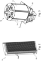
FIG. 2 is a see-through view of a fastener storage cassette according to one or more aspects of the present invention; -
FIG. 3 is a schematic view of a cassette holding module according to one or more aspects of the present invention; -
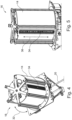
FIG. 4 is another schematic view of the cassette holding module show inFIG. 3 ; -
FIG. 5 is a side schematic view of the cassette holding module show inFIG. 3 ; -
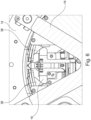
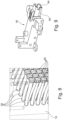
FIG. 6 is a closeup schematic view of a selection chamber assembly according to one or more aspects of the present invention; -
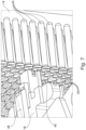
FIG. 7 is a closeup schematic view of the selection chamber assembly ofFIG. 6 proximate the fastener storage cassette ofFIG. 2 ; -
FIG. 8 is a closeup schematic view of a portion of the fastener storage cassette ofFIG. 2 ; -
FIG. 9 is a side perspective view of a selection chamber assembly according to one or more aspects of the present invention; -
FIG. 10 is a schematic view of a removal of a fastener from fastener storage cassette according to one or more aspects of the present invention; and, -
FIG. 11 is a schematic side of a device according to one or more aspects of the present invention configured for delivery of a removed fastener to an end effector. - The present invention is useful in a robotic assembly system to deliver fasteners from a storage cassette to an end effector of an assembly robot, with allowing for a wide range of fasteners to be stored and delivered as required during the assembly process.
- Turning to
FIG.1 , arobotic assembly system 10 having afastener delivery system 12 is shown. As will be described in more detail below, thefastener delivery system 12 includes one or more of the following: afastener storage cassette 14; acassette holding module 16; a selection chamber assembly 18 (seeFIG. 6 ); a delivery conduit 20 (seeFIG. 11 ); and an inspection sensor 22 (seeFIG. 11 ). - As shown in
FIG. 2 , thefastener storage cassette 14 has a plurality of cavities orchambers 24 for holding a fastener. Eachfastener storage cassette 14 may hold around 500 fasteners. The 500 fasteners may be the same type of fastener or 500 different types of fasteners, or some desired combination of numbers of different fasteners. In this manner, thefastener delivery system 12 of the present invention is not limited in the types of fasteners that can be accommodated in thefastener storage cassette 14 and handled by thefastener delivery system 12. - The
fastener storage cassette 14 may be provided with adata storage device 26, such as an RFID chip, or other electronic, magnetic, or printed data storage devices, including bar codes and QR codes, and similar storage devices, such that identification of the types of fasteners held in thefastener storage cassette 14 can be held in thedate storage devices 26. A data reader 28 (FIG. 3 ) can be provided which is configured to read the data contained on the data storage device and to provide such data to a controller of the fastener delivery system. The data reader may be located on thecassette holding module 16. - In the depicted embodiment shown in
FIG. 3 , six suchfastener storage cassette 14 can be carried on thecassette holding module 16 of thefastener delivery system 12 to provide a compact fastener delivery system in comparison with recently available systems. With such a compactfastener delivery system 12, thecassette holding module 16 may be easily transportable, and may also be located close to an end effector 30 (seeFIG. 11 ) of therobotic assembly system 10. Thecassette holding module 16 may have the plurality offastener storage cassettes 14 carried on a cylindrical outer surface thereof, with the proximal end of thefastener chambers 24 arranged radially inward and the distal end of thefastener chambers 24 arranged radially outward. - Turning to
FIGS. 4 and 5 , thefastener storage cassette 14 rotate (as shown by arrow 32) into position via an appropriate electronic controller and motor (not shown) to present the desiredfastener storage cassette 14 in a desired delivery position. Avertical selector 34 is moved alongarrow 36 to a location corresponding to the desired or appropriate fastener chamber 24 (containing the desired or appropriate fastener) to deliver the appropriate fastener to theend effector 30. In thefastener chambers 24, the fastener can be held loosely and preferably are stored with the head end of the fastener proximate the proximal end of thefastener chamber 24. - A pair of
retaining fingers 38 are moved out of the way by theselection chamber assembly 18, which is movably positioned on the inside of thecassette holding module 16. The pair of retainingfingers 38 are passively moved out of the way whenselection chamber assembly 18 moves forward (radially outward) towards thefastener storage cassette 14. - With reference to
FIGS. 7 to 10 , movement of afastener 46 from thefastener storage cassette 14 will be described. When theselection chamber assembly 18 is aligned with the correct fastener/cavity 24, an air blast from a nozzle 40 (seeFIGS 7 and9 ) carried on theselection chamber assembly 18 is sent through an air blast port 42 (seeFIGS. 7 and8 ) in thefastener storage cassette 14 associated with a particular fastener chamber carrying the desiredfastener 46. The air blast moves thefastener 46 from thefastener storage cassette 14 to a receivingspace 44 in theselection chamber assembly 18. - Thus, a separate
air blast port 42 is provided which connects with eachseparate fastener chamber 24. Theair blast nozzle 40 is carried on theselection chamber assembly 18 adjacent to the receivingspace 44 in theselection chamber assembly 18. The air blast from theair blast nozzle 40 into theair blast port 42 flows into a distal end of thefastener chamber 24 and pushes theloose fastener 46 out of thefastener storage cassette 14 at an open proximal end of thefastener chamber 24 and into the aligned receivingspace 44 in theselection chamber assembly 18. - When the
fastener 46 moves from thefastener storage cassette 14 into theselection chamber assembly 18, a blockingfinger assembly 48 is in an open position (e.g., raised), allowing thefastener 46 to enter the receivingspace 44. When thefastener 46 passes the blockingfinger assembly 48, the blockingfinger assembly 48 move to a closed position (e.g., lowered) and capture thefastener 46 in the receivingspace 44. Asensor 50 may be used to determine when thefastener 46 moves past the blockingfinger assembly 48. - An
air connection 52 may provide compressed air to actuate the blockingfinger assembly 48 and change its position (e.g., up or down). Asecond air connection 54 may be provided to provide air to move thefastener 46 at the appropriate time. - Turning to
FIG. 11 , with thefastener 46 in the receivingspace 44, theselection chamber assembly 18 is lowered to areceiver 56. Once theselection chamber assembly 18 is aligned with thereceiver 56, the blockingfinger assembly 48 may be moved to the open position and an air blast is used to eject thefastener 46 from theselection chamber assembly 18. - The
fastener 46 will be inspected for diameter, length, and shape in theinspection sensor 22 before being delivered to theend effector 30 in thedelivery conduit 20. If thefastener 46 is determined to be incorrect, thefastener 46 may be discarded instead of being delivered to theend effector 30. - Appropriate motors and actuators may be operated and controlled by an electronic controller, and all of these items may be arranged within the cassette holding module in a compact form, with a minimum amount of cabling required between the components, and a single power line and a single data line leading out of the cassette holding module, thereby allowing for easy cable management in comparison to presently available systems.
- By effecting movement of the selected fasteners with air blasts, the fastener delivery system can be placed in any orientation (vertical or horizontal) since gravity is not utilized for moving or holding the fasteners during the selection or delivery process. Any mention of orientation or position, such as "above" or "below", or "horizontal" or "vertical" is provided only to describe the system in the orientation shown in the drawings. It should be understood that the system could be rotated about any horizontal or vertical axis from the orientation shown in the drawings, and it will still work in the same manner as shown and described.
- The systems and devices described herein may include a controller or a computing device comprising a processing unit and a memory which has stored therein computer-executable instructions for implementing the processes described herein. The processing unit may comprise any suitable devices configured to cause a series of steps to be performed so as to implement the method such that instructions, when executed by the computing device or other programmable apparatus, may cause the functions/acts/steps specified in the methods described herein to be executed. The processing unit may comprise, for example, any type of general-purpose microprocessor or microcontroller, a digital signal processing (DSP) processor, a central processing unit (CPU), an integrated circuit, a field programmable gate array (FPGA), a reconfigurable processor, other suitably programmed or programmable logic circuits, or any combination thereof.
- The memory may be any suitable known or other machine-readable storage medium. The memory may comprise non-transitory computer readable storage medium such as, for example, but not limited to, an electronic, magnetic, optical, electromagnetic, infrared, or semiconductor system, apparatus, or device, or any suitable combination of the foregoing. The memory may include a suitable combination of any type of computer memory that is located either internally or externally to the device such as, for example, random-access memory (RAM), read-only memory (ROM), compact disc read-only memory (CDROM), electro-optical memory, magneto-optical memory, erasable programmable read-only memory (EPROM), and electrically-erasable programmable read-only memory (EEPROM), Ferroelectric RAM (FRAM) or the like. The memory may comprise any storage means (e.g., devices) suitable for retrievably storing the computer-executable instructions executable by processing unit.
- The methods and systems described herein may be implemented in a high-level procedural or object-oriented programming or scripting language, or a combination thereof, to communicate with or assist in the operation of the controller or computing device. Alternatively, the methods and systems described herein may be implemented in assembly or machine language. The language may be a compiled or interpreted language. Program code for implementing the methods and systems for detecting skew in a wing slat of an aircraft described herein may be stored on the storage media or the device, for example a ROM, a magnetic disk, an optical disc, a flash drive, or any other suitable storage media or device. The program code may be readable by a general or special-purpose programmable computer for configuring and operating the computer when the storage media or device is read by the computer to perform the procedures described herein.
- Computer-executable instructions may be in many forms, including program modules, executed by one or more computers or other devices. Generally, program modules include routines, programs, objects, components, data structures, etc., that perform particular tasks or implement particular abstract data types. Typically, the functionality of the program modules may be combined or distributed as desired in various embodiments.
- While at least one exemplary embodiment of the present invention(s) is disclosed herein, it should be understood that modifications, substitutions and alternatives may be apparent to one of ordinary skill in the art and can be made without departing from the scope of this disclosure. This disclosure is intended to cover any adaptations or variations of the exemplary embodiment(s). In addition, in this disclosure, the terms "comprise" or "comprising" do not exclude other elements or steps, the terms "a" or "one" do not exclude a plural number, and the term "or" means either or both. Furthermore, characteristics or steps which have been described may also be used in combination with other characteristics or steps and in any order unless the disclosure or context suggests otherwise.
Claims (10)
- Fastener delivery system (12), comprising:a fastener storage cassette (14),a cassette holding module (16), and,a selection chamber assembly (18),wherein the fastener storage cassette (14) includes a plurality of individual fastener chambers (24) each configured to loosely receive a fastener (46) to be selected and delivered, each fastener chamber (24) communicating with a separate air blast port (42), and,wherein the cassette holding module (16) is configured to hold a at least one fastener storage cassette (14).
- Fastener delivery system (12) according to claim 1, wherein the cassette holding module (16) and the selection chamber assembly (18) are movable relative to one another to allow the selection chamber assembly (18) to be aligned with a particular fastener chamber (24) of the fastener storage cassette (14).
- Fastener delivery system (12) according to any one of claims 1 or 2, wherein the selection chamber assembly (18) comprises a receiving space (44) configured to receive a selected fastener (46) and an air blast nozzle (40) configured to be aligned with the air blast port (42) associated with an individual fastener chamber (24) holding the selected fastener (46).
- Fastener delivery system (12) according to any one of the preceding claims, wherein the selection chamber assembly (18) comprises a retaining arrangement configured to capture and retain a selected fastener (46) within a receiving space (44) of the selection chamber assembly (18).
- Fastener delivery system (12) according to any one of the preceding claims, further comprising a delivery conduit (20).
- Fastener delivery system (12) according to claim 5, wherein the selection chamber assembly (18) comprises an air delivery system configured to selectively push a selected fastener (46) out of a receiving space (44) and into the delivery conduit (20).
- Fastener delivery system (12) according to claim 6, further comprising:
an inspection sensor (22) configured to inspect one or more of a diameter, a length, and a shape of the selected fastener (46). - Fastener delivery system (12) according to claim 7, wherein the inspection sensor (22) is located in the delivery conduit (20) and is configured to provide inspection data to a controller configured to compare a sensed diameter, length, shape or a combination thereof to a predetermined diameter, length, shape, or a combination thereof of the selected fastener (46).
- Fastener delivery system (12) according to claim 8, wherein when a comparison of the sensed and predetermined diameter, length and/or shape shows a difference greater than a set tolerance, then a rejection of the selected fastener (46) is made by the controller, but when no difference is detected, the air delivery system delivers the fastener (46) to an end effector of a robotic assembly system.
- Fastener storage cassette (14) for a fastener delivery system (12), comprising:a plurality of individual fastener chambers (24), each configured to loosely receive a fastener (46) to be selected and delivered, anda separate air blast port (42) communicating with each associated fastener chamber (24),wherein, a blast of air through one of the air blast ports (42) will flow into the associated fastener chamber (24) in a manner which will cause the fastener (46) loosely received in such fastener chamber (24) to be pushed out of the fastener chamber (24).
Applications Claiming Priority (1)
| Application Number | Priority Date | Filing Date | Title |
|---|---|---|---|
| US202263430308P | 2022-12-05 | 2022-12-05 |
Publications (1)
| Publication Number | Publication Date |
|---|---|
| EP4382225A1 true EP4382225A1 (en) | 2024-06-12 |
Family
ID=89119418
Family Applications (1)
| Application Number | Title | Priority Date | Filing Date |
|---|---|---|---|
| EP23214128.3A Pending EP4382225A1 (en) | 2022-12-05 | 2023-12-04 | Fastener delivery system |
Country Status (3)
| Country | Link |
|---|---|
| US (1) | US20240181579A1 (en) |
| EP (1) | EP4382225A1 (en) |
| CN (1) | CN118145281A (en) |
Families Citing this family (1)
| Publication number | Priority date | Publication date | Assignee | Title |
|---|---|---|---|---|
| US20250375895A1 (en) * | 2024-06-10 | 2025-12-11 | The Boeing Company | Fastener Installation Assembly, an End-Effector Tool, and a Method |
Citations (6)
| Publication number | Priority date | Publication date | Assignee | Title |
|---|---|---|---|---|
| DE3917310A1 (en) * | 1989-05-27 | 1990-11-29 | Kumeth Siegmund | Testing or measuring appts. for machined components - has two sensors at ends of conveyor section or conveyor serving as gauge and rejecting parts not satisfying measure |
| US5465868A (en) * | 1993-03-22 | 1995-11-14 | Bears S.R.L. | Automatic system for selecting and feeding preoriented rivets to riveting machines |
| WO2004007142A1 (en) * | 2002-07-12 | 2004-01-22 | F2 C2 System | Device for storing and dispensing parts in particular rivets |
| EP1916044A1 (en) * | 2006-10-26 | 2008-04-30 | Serra Soldadura, Sa | Device and method for storing and dispensing components, and storage and transport case used |
| WO2008124353A1 (en) * | 2007-04-06 | 2008-10-16 | The Boeing Company | Method and apparatus for installing fasteners |
| EP2460602A1 (en) * | 2010-12-03 | 2012-06-06 | Brötje-Automation GmbH | Rivet supply device |
Family Cites Families (5)
| Publication number | Priority date | Publication date | Assignee | Title |
|---|---|---|---|---|
| JPS5521332A (en) * | 1978-07-27 | 1980-02-15 | Matsushita Electric Ind Co Ltd | Device for separating and feeding tap-headed bar |
| US4830547A (en) * | 1984-12-07 | 1989-05-16 | The Boeing Company | Rivet manifold feed device |
| GB9816796D0 (en) * | 1998-08-03 | 1998-09-30 | Henrob Ltd | Improvements in or relating to fastening machines |
| DE102016118106A1 (en) * | 2016-09-26 | 2018-03-29 | Newfrey Llc | Magazine arrangement for joining elements and method for conveying joining elements within a magazine arrangement |
| CN109896297B (en) * | 2017-12-08 | 2021-03-16 | 泰科电子(上海)有限公司 | Automatic feeding system |
-
2023
- 2023-12-04 US US18/527,886 patent/US20240181579A1/en active Pending
- 2023-12-04 EP EP23214128.3A patent/EP4382225A1/en active Pending
- 2023-12-05 CN CN202311652595.4A patent/CN118145281A/en active Pending
Patent Citations (6)
| Publication number | Priority date | Publication date | Assignee | Title |
|---|---|---|---|---|
| DE3917310A1 (en) * | 1989-05-27 | 1990-11-29 | Kumeth Siegmund | Testing or measuring appts. for machined components - has two sensors at ends of conveyor section or conveyor serving as gauge and rejecting parts not satisfying measure |
| US5465868A (en) * | 1993-03-22 | 1995-11-14 | Bears S.R.L. | Automatic system for selecting and feeding preoriented rivets to riveting machines |
| WO2004007142A1 (en) * | 2002-07-12 | 2004-01-22 | F2 C2 System | Device for storing and dispensing parts in particular rivets |
| EP1916044A1 (en) * | 2006-10-26 | 2008-04-30 | Serra Soldadura, Sa | Device and method for storing and dispensing components, and storage and transport case used |
| WO2008124353A1 (en) * | 2007-04-06 | 2008-10-16 | The Boeing Company | Method and apparatus for installing fasteners |
| EP2460602A1 (en) * | 2010-12-03 | 2012-06-06 | Brötje-Automation GmbH | Rivet supply device |
Also Published As
| Publication number | Publication date |
|---|---|
| US20240181579A1 (en) | 2024-06-06 |
| CN118145281A (en) | 2024-06-07 |
Similar Documents
| Publication | Publication Date | Title |
|---|---|---|
| US7527764B2 (en) | Automatic system for conserving samples at a controlled temperature | |
| US12519004B2 (en) | Wafer aligner | |
| CN102112887B (en) | Handle storage devices | |
| EP3768081B1 (en) | Cryogenic storage system and method of transporting a sample in a cryogenic storage system | |
| US20240181579A1 (en) | Fastener delivery system | |
| EP1251549A2 (en) | Automatic guided vehicle, automatic guided vehicle system and wafer carrying method | |
| EP0674791B1 (en) | Integrated circuit card programming device | |
| US4775281A (en) | Apparatus and method for loading and unloading wafers | |
| EP3020658A1 (en) | Inventory management system using automated guided vehicle | |
| CN101689526A (en) | Apparatus for object processing | |
| US20040158348A1 (en) | Reticle storage system | |
| CN103042529A (en) | Workpiece takeout system, robot apparatus, and method for producing a to-be-processed material | |
| CN110770152A (en) | Production system with AGV for automatically outputting containers to extraction racks | |
| WO2001083171A1 (en) | Self teaching robotic wafer handling system | |
| KR19980080191A (en) | Cassette Carry-In / Out Device and Semiconductor Manufacturing Equipment | |
| EP2839935A1 (en) | Robot system | |
| US6168002B1 (en) | Control system for use with semiconductor device transporting and handling apparatus | |
| KR20180101149A (en) | Transfer unit and processing apparatus for processing using the same | |
| WO2023105544A1 (en) | Apparatus for archiving biological samples | |
| CN115649716A (en) | Warehousing system, stocking method and goods taking method | |
| WO2022249698A1 (en) | Take-out device, take-out system, and transport shelf | |
| US20240217042A1 (en) | Tool transport device | |
| EP4295996A1 (en) | Tool transport device | |
| KR20230156402A (en) | Component pick-up device, component placement device | |
| US6381516B1 (en) | Modular off-line micro device processing system |
Legal Events
| Date | Code | Title | Description |
|---|---|---|---|
| PUAI | Public reference made under article 153(3) epc to a published international application that has entered the european phase |
Free format text: ORIGINAL CODE: 0009012 |
|
| STAA | Information on the status of an ep patent application or granted ep patent |
Free format text: STATUS: THE APPLICATION HAS BEEN PUBLISHED |
|
| AK | Designated contracting states |
Kind code of ref document: A1 Designated state(s): AL AT BE BG CH CY CZ DE DK EE ES FI FR GB GR HR HU IE IS IT LI LT LU LV MC ME MK MT NL NO PL PT RO RS SE SI SK SM TR |
|
| STAA | Information on the status of an ep patent application or granted ep patent |
Free format text: STATUS: REQUEST FOR EXAMINATION WAS MADE |
|
| 17P | Request for examination filed |
Effective date: 20241121 |
|
| RBV | Designated contracting states (corrected) |
Designated state(s): AL AT BE BG CH CY CZ DE DK EE ES FI FR GB GR HR HU IE IS IT LI LT LU LV MC ME MK MT NL NO PL PT RO RS SE SI SK SM TR |