EP4382068A1 - Dentalwerkzeugsystem - Google Patents
Dentalwerkzeugsystem Download PDFInfo
- Publication number
- EP4382068A1 EP4382068A1 EP24164043.2A EP24164043A EP4382068A1 EP 4382068 A1 EP4382068 A1 EP 4382068A1 EP 24164043 A EP24164043 A EP 24164043A EP 4382068 A1 EP4382068 A1 EP 4382068A1
- Authority
- EP
- European Patent Office
- Prior art keywords
- tooth
- tool
- dental
- situation
- detection system
- Prior art date
- Legal status (The legal status is an assumption and is not a legal conclusion. Google has not performed a legal analysis and makes no representation as to the accuracy of the status listed.)
- Pending
Links
- 238000001514 detection method Methods 0.000 claims abstract description 45
- 230000001276 controlling effect Effects 0.000 claims abstract description 11
- 230000001105 regulatory effect Effects 0.000 claims abstract description 6
- 238000000034 method Methods 0.000 claims description 28
- 239000011521 glass Substances 0.000 claims description 25
- 230000003287 optical effect Effects 0.000 claims description 10
- 238000006116 polymerization reaction Methods 0.000 claims description 7
- 238000005259 measurement Methods 0.000 claims description 4
- 238000004364 calculation method Methods 0.000 description 7
- 230000033228 biological regulation Effects 0.000 description 4
- 230000006870 function Effects 0.000 description 4
- 208000002925 dental caries Diseases 0.000 description 3
- 239000000463 material Substances 0.000 description 3
- 238000004422 calculation algorithm Methods 0.000 description 2
- 230000006378 damage Effects 0.000 description 2
- 238000010586 diagram Methods 0.000 description 2
- 230000000694 effects Effects 0.000 description 2
- 210000003128 head Anatomy 0.000 description 2
- 210000000214 mouth Anatomy 0.000 description 2
- 210000001525 retina Anatomy 0.000 description 2
- 206010061217 Infestation Diseases 0.000 description 1
- 238000013528 artificial neural network Methods 0.000 description 1
- 230000003190 augmentative effect Effects 0.000 description 1
- 238000002591 computed tomography Methods 0.000 description 1
- 230000001419 dependent effect Effects 0.000 description 1
- 230000004438 eyesight Effects 0.000 description 1
- 239000007943 implant Substances 0.000 description 1
- 238000001646 magnetic resonance method Methods 0.000 description 1
- 238000012067 mathematical method Methods 0.000 description 1
- 230000010287 polarization Effects 0.000 description 1
- 238000001454 recorded image Methods 0.000 description 1
- 239000004984 smart glass Substances 0.000 description 1
- 230000002123 temporal effect Effects 0.000 description 1
- 230000016776 visual perception Effects 0.000 description 1
Images


Classifications
-
- A—HUMAN NECESSITIES
- A61—MEDICAL OR VETERINARY SCIENCE; HYGIENE
- A61C—DENTISTRY; APPARATUS OR METHODS FOR ORAL OR DENTAL HYGIENE
- A61C5/00—Filling or capping teeth
- A61C5/40—Implements for surgical treatment of the roots or nerves of the teeth; Nerve needles; Methods or instruments for medication of the roots
- A61C5/44—Means for controlling working depth, e.g. supports or boxes with depth-gauging means, stop positioners or files with adjustably-mounted handles
-
- A—HUMAN NECESSITIES
- A61—MEDICAL OR VETERINARY SCIENCE; HYGIENE
- A61B—DIAGNOSIS; SURGERY; IDENTIFICATION
- A61B34/00—Computer-aided surgery; Manipulators or robots specially adapted for use in surgery
- A61B34/20—Surgical navigation systems; Devices for tracking or guiding surgical instruments, e.g. for frameless stereotaxis
-
- A—HUMAN NECESSITIES
- A61—MEDICAL OR VETERINARY SCIENCE; HYGIENE
- A61B—DIAGNOSIS; SURGERY; IDENTIFICATION
- A61B1/00—Instruments for performing medical examinations of the interior of cavities or tubes of the body by visual or photographical inspection, e.g. endoscopes; Illuminating arrangements therefor
- A61B1/00002—Operational features of endoscopes
- A61B1/00043—Operational features of endoscopes provided with output arrangements
- A61B1/00045—Display arrangement
- A61B1/00048—Constructional features of the display
-
- A—HUMAN NECESSITIES
- A61—MEDICAL OR VETERINARY SCIENCE; HYGIENE
- A61B—DIAGNOSIS; SURGERY; IDENTIFICATION
- A61B1/00—Instruments for performing medical examinations of the interior of cavities or tubes of the body by visual or photographical inspection, e.g. endoscopes; Illuminating arrangements therefor
- A61B1/00163—Optical arrangements
- A61B1/00193—Optical arrangements adapted for stereoscopic vision
-
- A—HUMAN NECESSITIES
- A61—MEDICAL OR VETERINARY SCIENCE; HYGIENE
- A61B—DIAGNOSIS; SURGERY; IDENTIFICATION
- A61B1/00—Instruments for performing medical examinations of the interior of cavities or tubes of the body by visual or photographical inspection, e.g. endoscopes; Illuminating arrangements therefor
- A61B1/24—Instruments for performing medical examinations of the interior of cavities or tubes of the body by visual or photographical inspection, e.g. endoscopes; Illuminating arrangements therefor for the mouth, i.e. stomatoscopes, e.g. with tongue depressors; Instruments for opening or keeping open the mouth
-
- A—HUMAN NECESSITIES
- A61—MEDICAL OR VETERINARY SCIENCE; HYGIENE
- A61B—DIAGNOSIS; SURGERY; IDENTIFICATION
- A61B90/00—Instruments, implements or accessories specially adapted for surgery or diagnosis and not covered by any of the groups A61B1/00 - A61B50/00, e.g. for luxation treatment or for protecting wound edges
- A61B90/36—Image-producing devices or illumination devices not otherwise provided for
- A61B90/37—Surgical systems with images on a monitor during operation
-
- A—HUMAN NECESSITIES
- A61—MEDICAL OR VETERINARY SCIENCE; HYGIENE
- A61C—DENTISTRY; APPARATUS OR METHODS FOR ORAL OR DENTAL HYGIENE
- A61C5/00—Filling or capping teeth
- A61C5/30—Securing inlays, onlays or crowns
-
- G—PHYSICS
- G02—OPTICS
- G02B—OPTICAL ELEMENTS, SYSTEMS OR APPARATUS
- G02B27/00—Optical systems or apparatus not provided for by any of the groups G02B1/00 - G02B26/00, G02B30/00
- G02B27/01—Head-up displays
- G02B27/017—Head mounted
-
- G—PHYSICS
- G02—OPTICS
- G02B—OPTICAL ELEMENTS, SYSTEMS OR APPARATUS
- G02B27/00—Optical systems or apparatus not provided for by any of the groups G02B1/00 - G02B26/00, G02B30/00
- G02B27/01—Head-up displays
- G02B27/017—Head mounted
- G02B27/0172—Head mounted characterised by optical features
-
- G—PHYSICS
- G06—COMPUTING; CALCULATING OR COUNTING
- G06T—IMAGE DATA PROCESSING OR GENERATION, IN GENERAL
- G06T7/00—Image analysis
- G06T7/0002—Inspection of images, e.g. flaw detection
- G06T7/0012—Biomedical image inspection
-
- G—PHYSICS
- G06—COMPUTING; CALCULATING OR COUNTING
- G06T—IMAGE DATA PROCESSING OR GENERATION, IN GENERAL
- G06T7/00—Image analysis
- G06T7/70—Determining position or orientation of objects or cameras
-
- G—PHYSICS
- G06—COMPUTING; CALCULATING OR COUNTING
- G06V—IMAGE OR VIDEO RECOGNITION OR UNDERSTANDING
- G06V20/00—Scenes; Scene-specific elements
- G06V20/10—Terrestrial scenes
-
- G—PHYSICS
- G16—INFORMATION AND COMMUNICATION TECHNOLOGY [ICT] SPECIALLY ADAPTED FOR SPECIFIC APPLICATION FIELDS
- G16H—HEALTHCARE INFORMATICS, i.e. INFORMATION AND COMMUNICATION TECHNOLOGY [ICT] SPECIALLY ADAPTED FOR THE HANDLING OR PROCESSING OF MEDICAL OR HEALTHCARE DATA
- G16H30/00—ICT specially adapted for the handling or processing of medical images
- G16H30/40—ICT specially adapted for the handling or processing of medical images for processing medical images, e.g. editing
-
- H—ELECTRICITY
- H04—ELECTRIC COMMUNICATION TECHNIQUE
- H04N—PICTORIAL COMMUNICATION, e.g. TELEVISION
- H04N13/00—Stereoscopic video systems; Multi-view video systems; Details thereof
- H04N13/20—Image signal generators
- H04N13/204—Image signal generators using stereoscopic image cameras
- H04N13/239—Image signal generators using stereoscopic image cameras using two 2D image sensors having a relative position equal to or related to the interocular distance
-
- H—ELECTRICITY
- H04—ELECTRIC COMMUNICATION TECHNIQUE
- H04N—PICTORIAL COMMUNICATION, e.g. TELEVISION
- H04N23/00—Cameras or camera modules comprising electronic image sensors; Control thereof
- H04N23/57—Mechanical or electrical details of cameras or camera modules specially adapted for being embedded in other devices
-
- A—HUMAN NECESSITIES
- A61—MEDICAL OR VETERINARY SCIENCE; HYGIENE
- A61B—DIAGNOSIS; SURGERY; IDENTIFICATION
- A61B17/00—Surgical instruments, devices or methods, e.g. tourniquets
- A61B2017/00017—Electrical control of surgical instruments
- A61B2017/00216—Electrical control of surgical instruments with eye tracking or head position tracking control
-
- A—HUMAN NECESSITIES
- A61—MEDICAL OR VETERINARY SCIENCE; HYGIENE
- A61B—DIAGNOSIS; SURGERY; IDENTIFICATION
- A61B34/00—Computer-aided surgery; Manipulators or robots specially adapted for use in surgery
- A61B34/20—Surgical navigation systems; Devices for tracking or guiding surgical instruments, e.g. for frameless stereotaxis
- A61B2034/2046—Tracking techniques
- A61B2034/2048—Tracking techniques using an accelerometer or inertia sensor
-
- A—HUMAN NECESSITIES
- A61—MEDICAL OR VETERINARY SCIENCE; HYGIENE
- A61B—DIAGNOSIS; SURGERY; IDENTIFICATION
- A61B34/00—Computer-aided surgery; Manipulators or robots specially adapted for use in surgery
- A61B34/20—Surgical navigation systems; Devices for tracking or guiding surgical instruments, e.g. for frameless stereotaxis
- A61B2034/2046—Tracking techniques
- A61B2034/2055—Optical tracking systems
-
- A—HUMAN NECESSITIES
- A61—MEDICAL OR VETERINARY SCIENCE; HYGIENE
- A61B—DIAGNOSIS; SURGERY; IDENTIFICATION
- A61B34/00—Computer-aided surgery; Manipulators or robots specially adapted for use in surgery
- A61B34/20—Surgical navigation systems; Devices for tracking or guiding surgical instruments, e.g. for frameless stereotaxis
- A61B2034/2046—Tracking techniques
- A61B2034/2065—Tracking using image or pattern recognition
-
- A—HUMAN NECESSITIES
- A61—MEDICAL OR VETERINARY SCIENCE; HYGIENE
- A61B—DIAGNOSIS; SURGERY; IDENTIFICATION
- A61B90/00—Instruments, implements or accessories specially adapted for surgery or diagnosis and not covered by any of the groups A61B1/00 - A61B50/00, e.g. for luxation treatment or for protecting wound edges
- A61B90/36—Image-producing devices or illumination devices not otherwise provided for
- A61B2090/364—Correlation of different images or relation of image positions in respect to the body
- A61B2090/365—Correlation of different images or relation of image positions in respect to the body augmented reality, i.e. correlating a live optical image with another image
-
- A—HUMAN NECESSITIES
- A61—MEDICAL OR VETERINARY SCIENCE; HYGIENE
- A61B—DIAGNOSIS; SURGERY; IDENTIFICATION
- A61B90/00—Instruments, implements or accessories specially adapted for surgery or diagnosis and not covered by any of the groups A61B1/00 - A61B50/00, e.g. for luxation treatment or for protecting wound edges
- A61B90/36—Image-producing devices or illumination devices not otherwise provided for
- A61B90/37—Surgical systems with images on a monitor during operation
- A61B2090/371—Surgical systems with images on a monitor during operation with simultaneous use of two cameras
-
- A—HUMAN NECESSITIES
- A61—MEDICAL OR VETERINARY SCIENCE; HYGIENE
- A61B—DIAGNOSIS; SURGERY; IDENTIFICATION
- A61B90/00—Instruments, implements or accessories specially adapted for surgery or diagnosis and not covered by any of the groups A61B1/00 - A61B50/00, e.g. for luxation treatment or for protecting wound edges
- A61B90/36—Image-producing devices or illumination devices not otherwise provided for
- A61B90/37—Surgical systems with images on a monitor during operation
- A61B2090/372—Details of monitor hardware
-
- A—HUMAN NECESSITIES
- A61—MEDICAL OR VETERINARY SCIENCE; HYGIENE
- A61B—DIAGNOSIS; SURGERY; IDENTIFICATION
- A61B90/00—Instruments, implements or accessories specially adapted for surgery or diagnosis and not covered by any of the groups A61B1/00 - A61B50/00, e.g. for luxation treatment or for protecting wound edges
- A61B90/50—Supports for surgical instruments, e.g. articulated arms
- A61B2090/502—Headgear, e.g. helmet, spectacles
-
- A—HUMAN NECESSITIES
- A61—MEDICAL OR VETERINARY SCIENCE; HYGIENE
- A61B—DIAGNOSIS; SURGERY; IDENTIFICATION
- A61B5/00—Measuring for diagnostic purposes; Identification of persons
- A61B5/0059—Measuring for diagnostic purposes; Identification of persons using light, e.g. diagnosis by transillumination, diascopy, fluorescence
- A61B5/0082—Measuring for diagnostic purposes; Identification of persons using light, e.g. diagnosis by transillumination, diascopy, fluorescence adapted for particular medical purposes
- A61B5/0088—Measuring for diagnostic purposes; Identification of persons using light, e.g. diagnosis by transillumination, diascopy, fluorescence adapted for particular medical purposes for oral or dental tissue
-
- A—HUMAN NECESSITIES
- A61—MEDICAL OR VETERINARY SCIENCE; HYGIENE
- A61B—DIAGNOSIS; SURGERY; IDENTIFICATION
- A61B6/00—Apparatus or devices for radiation diagnosis; Apparatus or devices for radiation diagnosis combined with radiation therapy equipment
- A61B6/50—Apparatus or devices for radiation diagnosis; Apparatus or devices for radiation diagnosis combined with radiation therapy equipment specially adapted for specific body parts; specially adapted for specific clinical applications
- A61B6/51—Apparatus or devices for radiation diagnosis; Apparatus or devices for radiation diagnosis combined with radiation therapy equipment specially adapted for specific body parts; specially adapted for specific clinical applications for dentistry
-
- A—HUMAN NECESSITIES
- A61—MEDICAL OR VETERINARY SCIENCE; HYGIENE
- A61B—DIAGNOSIS; SURGERY; IDENTIFICATION
- A61B90/00—Instruments, implements or accessories specially adapted for surgery or diagnosis and not covered by any of the groups A61B1/00 - A61B50/00, e.g. for luxation treatment or for protecting wound edges
- A61B90/90—Identification means for patients or instruments, e.g. tags
- A61B90/94—Identification means for patients or instruments, e.g. tags coded with symbols, e.g. text
- A61B90/96—Identification means for patients or instruments, e.g. tags coded with symbols, e.g. text using barcodes
-
- A—HUMAN NECESSITIES
- A61—MEDICAL OR VETERINARY SCIENCE; HYGIENE
- A61B—DIAGNOSIS; SURGERY; IDENTIFICATION
- A61B90/00—Instruments, implements or accessories specially adapted for surgery or diagnosis and not covered by any of the groups A61B1/00 - A61B50/00, e.g. for luxation treatment or for protecting wound edges
- A61B90/90—Identification means for patients or instruments, e.g. tags
- A61B90/98—Identification means for patients or instruments, e.g. tags using electromagnetic means, e.g. transponders
-
- G—PHYSICS
- G02—OPTICS
- G02B—OPTICAL ELEMENTS, SYSTEMS OR APPARATUS
- G02B27/00—Optical systems or apparatus not provided for by any of the groups G02B1/00 - G02B26/00, G02B30/00
- G02B27/01—Head-up displays
- G02B27/0101—Head-up displays characterised by optical features
- G02B2027/0127—Head-up displays characterised by optical features comprising devices increasing the depth of field
-
- G—PHYSICS
- G02—OPTICS
- G02B—OPTICAL ELEMENTS, SYSTEMS OR APPARATUS
- G02B27/00—Optical systems or apparatus not provided for by any of the groups G02B1/00 - G02B26/00, G02B30/00
- G02B27/01—Head-up displays
- G02B27/0101—Head-up displays characterised by optical features
- G02B2027/0138—Head-up displays characterised by optical features comprising image capture systems, e.g. camera
-
- G—PHYSICS
- G02—OPTICS
- G02B—OPTICAL ELEMENTS, SYSTEMS OR APPARATUS
- G02B27/00—Optical systems or apparatus not provided for by any of the groups G02B1/00 - G02B26/00, G02B30/00
- G02B27/01—Head-up displays
- G02B27/0101—Head-up displays characterised by optical features
- G02B2027/014—Head-up displays characterised by optical features comprising information/image processing systems
-
- G—PHYSICS
- G02—OPTICS
- G02B—OPTICAL ELEMENTS, SYSTEMS OR APPARATUS
- G02B27/00—Optical systems or apparatus not provided for by any of the groups G02B1/00 - G02B26/00, G02B30/00
- G02B27/01—Head-up displays
- G02B27/0101—Head-up displays characterised by optical features
- G02B2027/0141—Head-up displays characterised by optical features characterised by the informative content of the display
-
- G—PHYSICS
- G02—OPTICS
- G02B—OPTICAL ELEMENTS, SYSTEMS OR APPARATUS
- G02B27/00—Optical systems or apparatus not provided for by any of the groups G02B1/00 - G02B26/00, G02B30/00
- G02B27/01—Head-up displays
- G02B27/017—Head mounted
- G02B2027/0178—Eyeglass type
-
- G—PHYSICS
- G06—COMPUTING; CALCULATING OR COUNTING
- G06T—IMAGE DATA PROCESSING OR GENERATION, IN GENERAL
- G06T2207/00—Indexing scheme for image analysis or image enhancement
- G06T2207/10—Image acquisition modality
- G06T2207/10016—Video; Image sequence
-
- G—PHYSICS
- G06—COMPUTING; CALCULATING OR COUNTING
- G06T—IMAGE DATA PROCESSING OR GENERATION, IN GENERAL
- G06T2207/00—Indexing scheme for image analysis or image enhancement
- G06T2207/30—Subject of image; Context of image processing
- G06T2207/30004—Biomedical image processing
- G06T2207/30036—Dental; Teeth
-
- G—PHYSICS
- G06—COMPUTING; CALCULATING OR COUNTING
- G06V—IMAGE OR VIDEO RECOGNITION OR UNDERSTANDING
- G06V2201/00—Indexing scheme relating to image or video recognition or understanding
- G06V2201/03—Recognition of patterns in medical or anatomical images
- G06V2201/034—Recognition of patterns in medical or anatomical images of medical instruments
Definitions
- the present invention relates to a dental tool system and a method for controlling a dental tool.
- Dental tools used for dental treatment can be used incorrectly. This can lead to irreparable damage to a patient during dental treatment.
- the present object is achieved by a dental tool system, with a detection system for detecting a spatial position of a tooth or a tooth situation and a spatial tool position of a tool; and a device for controlling or regulating the tool on the basis of the detected tool position in relation to the position of the tooth or the detected tooth situation.
- the detection of the position of the tooth or the tooth situation can be carried out by means of an optical method or an X-ray method.
- the electronic detection system can be any detection system, with which the position of the tooth or the tooth situation can be maintained.
- the control or regulation can be carried out by calculating a spatial distance between the tool position and the position of the tooth or the tooth situation.
- the control or regulation based on the detected tool position in relation to the position of the tooth or the tooth situation can be carried out, for example, if the tool position is outside a predetermined spatial area from the position of the tooth or the tooth situation or if the distance of the tool position to the position of the tooth or the tooth situation exceeds or falls below a predetermined distance.
- the tooth for detecting the position of the tooth or the tooth situation can be selected via a user interface. The detection of the position of the tooth or the tooth situation and the tool position can take place continuously in real time.
- the dental tool system for example, achieves the technical advantage of ensuring correct use of the dental tool in relation to the tooth or the area to be treated and position-based control of the tool can be carried out.
- the tooth situation is, for example, a situation of the tooth or the tooth root, which is determined by the shape, the interior or a caries infestation.
- the tooth situation can be determined by any spatial area of the tooth that requires processing with the tool.
- a drill can be used as a tool based on the position of the tooth situation as long as it is working on a carious area of the tooth.
- the information about the tooth situation can be for example, using an X-ray procedure.
- the depth information or X-ray images can indicate the position of the caries in the tooth.
- an optical recording device of the electronic detection system is integrated into data glasses.
- the data glasses are an electronic device worn as glasses, with which additional information can be optically displayed to a user in addition to natural visual perception.
- the data glasses can use a display device to superimpose additional information on an image that is perceived by the wearer's eye.
- the display device includes, for example, a screen close to the eye or a projector for direct projection onto the retina.
- the dental tool system is designed to visually display an error on a display device of the data glasses.
- the error is, for example, an error based on the detected tool position in relation to the position of the tooth or the tooth situation.
- the error occurs, for example, when the tool falls below or exceeds a certain distance from the tooth. This achieves the technical advantage, for example, that the user can immediately recognize an incorrect position of the tool.
- the detection system comprises a stereoscopic detection system with a first and a second camera. This achieves the technical advantage that the positions can be recorded with little technical effort and the detection system can be easily integrated into data glasses.
- the detection system comprises a camera for detecting the position of the tooth or the tooth situation and the tool position based on a time-of-flight measurement of light.
- the detection system comprises a projection device for projecting a light pattern.
- the detection system can detect the projected light pattern. Based on the detected light pattern, the spatial position of the tooth or the tooth situation can be calculated. This achieves the technical advantage, for example, of achieving precise position detection.
- the detection system is designed to determine the position of the tooth or the tooth situation and the tool position based on a temporal sequence of images. This achieves the technical advantage, for example, that the positions of the tooth or the tooth situation and the tool position can be determined in a simple and precise manner. Each additional image in the sequence increases the accuracy of the determined position of the tooth or the tooth situation and the tool position. Special computer algorithms can be used for this.
- the electronic detection system is designed to determine a period of time in which the tool position lies within a predetermined spatial area in relation to the position of the tooth or the tooth situation.
- the electronic detection system is designed to optically or electronically recognize the type of tool used.
- the optical recognition of the tool takes place, for example, by comparing a recorded image of the tool with a previously stored image of the tool.
- the electronic recognition of the tool takes place, for example, wirelessly using electromagnetic waves.
- the tool can comprise a transmitter-receiver system for the automatic and contactless identification of the tool using radio waves.
- an RFID chip is arranged in the tool, which identifies the tool and is read by a receiver. This achieves the technical advantage, for example, that a suitable control can be automatically selected based on the recognized tool.
- the tool comprises a polymerization lamp, a dental drill, an endoscope, a camera, a scanner, a mirror, a light curing device, a Treatment chair, a light source for diagnostics or a light source for color determination.
- the detection system comprises an autofocus or zoom function for detecting the position of the tooth or the tooth situation and/or tool position.
- the autofocus function allows automatic focusing by adjusting a camera setting to the distance between the camera and the tooth or tool and the tooth or tool is shown in sharp focus.
- the zoom function allows continuous adjustment of the image section to the tooth or tool. This achieves the technical advantage, for example, of simplifying the operation and handling of the dental tool system.
- the detection system is designed to determine the spatial position of the tooth or the tooth situation based on a sequence of tooth images of the tooth that have been obtained from different viewing angles. This achieves the technical advantage, for example, of achieving simple and rapid position detection.
- the object is achieved by a method for controlling a dental tool, comprising the steps of detecting a spatial position of a tooth or a tooth situation and a spatial tool position of a tool; and controlling or regulating the tool on the basis of the detected tool position in relation to the position of the tooth or the Tooth situation.
- Control or regulation based on the recorded tool position in relation to the position of the tooth or the tooth situation can be carried out, for example, if the tool position is outside a predetermined spatial area for the position of the tooth or the tooth situation.
- the method achieves the same technical advantages as the dental tool system according to the first aspect.
- an error is displayed optically on a display device of data glasses. This also achieves the technical advantage, for example, of simplifying the structure of the dental tool system.
- the position of the tooth or the tooth situation and the tool position are recorded by a stereoscopic detection system or by a detection system based on a time-of-flight measurement. This also achieves the technical advantage that the positions can be determined quickly and with a high degree of accuracy.
- the position of the tooth or the tooth situation and the tool position are determined on the basis of a sequence of images. This also achieves the technical advantage that the position of the tooth or the tooth situation and the tool position can be determined in a simple and precise manner.
- a period of time is determined in which the
- the tool position is within the specified spatial area for the position of the tooth or the tooth situation. This also provides the technical advantage that the tool can be time-controlled.
- the type of tool used is optically recognized by the detection system. This also achieves the technical advantage that a suitable control can be automatically selected based on the recognized tool.
- Fig.1 shows a schematic view of a dental tool system 100.
- the dental tool system 100 serves to control or regulate a tool 107 that is used for a dental treatment.
- the tool 107 can be, for example, a polymerization lamp, a dental drill, an endoscope, a camera, a scanner, a mirror, a light source for diagnostics or a light source for color determination.
- the tool 107 can be any controllable tool that is used as part of a dental treatment.
- the control of the tool 107 is based on a recorded tool position 103-W and a position 103-Z of a tooth 115 or a tooth situation.
- the position 103-Z of the tooth 115 can not only be the position of a natural tooth, but also the position of an artificial tooth, such as a bridge, a partial denture, or even an implant or an abutment.
- the tooth situation is, for example, the area of caries or the spatial inner area of the tooth 115.
- the tool position 103-W and the position 103-Z of the tooth 115 or the tooth situation can be detected by an optical detection system 101, an X-ray method, a magnetic resonance method or a computed tomography method.
- the tool position 103-W or the position 103-Z can also be detected by radio tags (RFID chips) that are integrated in the tool 107 or the tooth 115.
- RFID chips radio tags
- the tool position 103-W or the position 103-Z of the tooth 115 or the tooth situation can also be determined using a Kalman filter, which helps to get closer to calculating the actual position of the tool 107.
- the Kalman filter as a mathematical method bridges missing measured values or combines different data, such as optical data and data from an integrated, inertial measuring unit (IMU). In general, however, all methods that can be used to determine the tool position 103-W or the position 103-Z of the tooth 115 or the tooth situation are suitable.
- the electronic recording system 101 generates, for example, a data set that includes or describes the position of the tooth 115 as well as the tool 107.
- the tool position 103-W and the position 103-Z of the tooth 115 or the tooth situation can be specified by three-dimensional coordinates in any reference coordinate system.
- the position 103-Z of the tooth 115 is, for example, the center of the tooth 115 and the tool position 103-W is the center of a drill head. In general, however, the respective position can also be given by other reference points, since the coordinate systems defined in this way can be easily converted.
- the electronic recording system 101 comprises, for example, a stereoscopic camera system with two cameras 113-1, 113-2.
- the tool position 103-W and the position 103-Z of the tooth 115 or the tooth situation can be determined and reconstructed in a simple manner by the stereoscopic recording with the two cameras 113-1, 113-2.
- the tool position 103-W and the position 103-Z of the tooth 115 or the tooth situation can be calculated using a computer algorithm from the respective images of the cameras 113-1, 113-2 at different parallax angles or by comparing the images.
- the detection system 101 can also include a camera that determines individual distances using a time-of-flight camera (TOF camera).
- TOF camera time-of-flight camera
- the oral cavity with the tooth 115 and the tool 107 is illuminated using a light pulse and the time it takes for the light to reach the object and back again is measured for each pixel. This time is directly proportional to the distance.
- the camera provides a spatial model and, for each pixel, the distance of the tooth depicted on it. 115 and the tool, so that the respective positions of the tooth 115 and the tool 107 can be calculated.
- the detection system 101 can also determine the tool position 103-W and the position 103-Z of the tooth 115 or the tooth situation based on a sequence of tooth images of the tooth 115 that have been obtained from different viewing angles. For this purpose, a calculation method can be used that reconstructs the tool position 103-W and the position 103-Z of the tooth 115 or the tooth situation from the individual images. For this purpose, in addition to the tool position 103-W and position 103-Z of the tooth 115 or the tooth situation, information about the spatial position of the detection system 101 can be used.
- the determined tool position 103-W and the position 103-Z of the tooth 115 or the tooth situation are fed to an electronic calculation device 117 as a data set.
- the calculation device 117 can, for example, determine whether the tool position 103-W is outside or within a predetermined spatial area 119 for the position 103-Z of the tooth 115 or the tooth situation.
- the spatial area 119 can be set automatically based on the tool 107 used.
- the spatial area 119 can, for example, be spherical around the position 103-Z of the tooth 115 or the tooth situation.
- the spatial area 119 can also have any other spatial shape.
- the spatial area 119 can have different dimensions when a polymerization lamp is used as the tool 107 than when a drill is used as the tool 107.
- An electronic control device 105 controls the tool 107 based on the detected tool position 103-W in relation to the position 103-Z of the tooth 115 or the tooth situation.
- a control scheme tailored to the tool 107 can be used for this purpose.
- a message can be issued to a user of the dental tool system 100 if the tool 107 is outside or inside the predetermined spatial area 119.
- the user can be given haptic, acoustic or optical feedback about the tool 107.
- the dental tool system 100 can be designed to generate an electronic file that documents a treatment process, such as a video file or CAD file.
- a treatment process such as a video file or CAD file.
- the recorded tool positions 103-W and the positions 103-Z of the tooth 115 or the tooth situation can be stored in this file.
- information about the treatment can be permanently stored electronically so that the processing of the tooth 115 can be tracked and assessed retrospectively on the basis of the electronic file.
- the electronic calculation device 117 and the control device 105 are each formed, for example, by a software module that is executed on a computer device with a processor and an electronic memory for storing the software module and the data sets.
- the calculation device 117 or the control device 105 can be designed to calculate a tooth shape based on captured optical images.
- the tooth shape is, for example, the actual spatial shape of a natural tooth, a bridge or a crown.
- the tool 107 is, for example, a polymerization lamp for hardening a filling material, it can be automatically switched on or off as soon as it is in the specified spatial area 119 around the tooth 115. This can ensure that the polymerization lamp illuminates the correct tooth 115. In addition, the safety of the treatment can be improved and an increased temperature of the pulp caused by the polymerization lamp can be avoided.
- the tool position 103-W can be used to determine how long the tool 107 is within the spatial area 119, i.e. a period of time.
- the tool 107 is a dental drill, it can only be activated once it is in the predetermined spatial area 119 around the tooth 115. If the dental drill leaves the predetermined spatial area 119 around the tooth 115, it can be automatically switched off or the rotation speed can be reduced. This can prevent injuries caused by the dental drill in the area of the oral cavity.
- a light curing device is used as tool 107, it can be detected whether it is held in a suitable position to cure the material to be cured.
- the control or regulation of the light curing device on the basis of the detected tool position in relation to position 103-Z of tooth 115 can be carried out, for example, by automatically switching the light curing device on as soon as it falls below a predetermined distance from position 103-Z or automatically switching it off as soon as it falls below a predetermined distance from position 103-Z.
- a time period or light intensity of the Lighting can be controlled.
- the light curing device can also control the light intensity, the wavelength or a degree of polarization of the emitted light depending on the detected tool position 103-W in relation to the position 103-Z.
- the properties can be determined by measuring the wavelength and its effect on its surroundings.
- a treatment chair as a dental tool 107, it can be moved or adjusted depending on the tool position in relation to position 103-Z if it is too far away or lighting conditions are not appropriate.
- other tools 107 can also be controlled according to their properties on the basis of the detected tool position 103-W in relation to position 103-Z.
- the detection system 101 or the calculation device 117 can be designed to optically recognize the type of tool used.
- the type indicates, for example, which specific type and model of the tool 107 used is.
- the type of tool 107 can be determined based on an image comparison with previously stored digital images, for example using neural networks. Otherwise, the tools 107 could also be provided with a miniaturized bar or QR code, by which the type of tool 107 can be recognized.
- the spatial area 119 for the tool 107 can in turn be automatically selected.
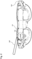
- Fig.2 shows a data glasses 111 for viewing the dental tool system 100.
- One or more optical Recording devices of the electronic detection system 101 can be integrated into these data glasses 111. This increases the manageability of the dental tool control system 100.
- the detection system 101 can also be provided as a separate device with which the tool position 103-W and the position 103-Z of the tooth 115 or the tooth situation are determined.
- the data glasses 111 are a portable device that is able to virtually project information in front of the eyes of the wearer, while the wearer can still visually perceive the environment. This allows information to be displayed and added in the wearer's field of vision.
- the data glasses 111 comprise a display device 121, which can be formed from a screen close to the eye or a projector for direct projection onto the retina.
- the data glasses 111 can additionally include sensors for detecting the movement of the head or for detecting the spatial position of the data glasses 111, such as a gyro sensor.
- the spatial position of the data glasses 111 can also be determined on the basis of predetermined optical reference points that are arranged in the environment of the data glasses 111, for example by means of trilateration or triangulation.
- the spatial position of the data glasses 111 can be taken into account when determining and calculating the tool position 103-W and the position 103-Z of the tooth 115 or the tooth situation, so that the accuracy of the determined tool position 103-W and position 103-Z of the tooth 115 or the tooth situation is increased.
- the data glasses 111 can also display the spatial area 119 for the tool 107.
- This spatial area 119 can be optically superimposed on the visually perceived image, for example by means of a color highlight or a dashed line.
- errors or warnings can be optically displayed on the data glasses 111 when using the tool 107.
- Fig.3 shows a block diagram of a method for controlling the dental tool.
- the method comprises step S101 of optically detecting the spatial position 103-Z of the tooth 115 or the tooth situation and a spatial tool position 103-W of the tool 107.
- the detection of the spatial position 103-Z of the tooth 115 or the tooth situation and the spatial tool position 103-W can take place continuously and in real time.
- the tool 107 is controlled on the basis of the detected tool position 103-W in relation to the position 103-Z of the tooth 115 or the tooth situation. Treatment errors can thereby be avoided and the handling of tools 107 can be increased.
- All method steps can be implemented by devices suitable for carrying out the respective method step. All functions performed by material features can be a method step of a method.
Landscapes
- Health & Medical Sciences (AREA)
- Engineering & Computer Science (AREA)
- Life Sciences & Earth Sciences (AREA)
- Surgery (AREA)
- General Health & Medical Sciences (AREA)
- Nuclear Medicine, Radiotherapy & Molecular Imaging (AREA)
- Physics & Mathematics (AREA)
- Public Health (AREA)
- Veterinary Medicine (AREA)
- Animal Behavior & Ethology (AREA)
- Medical Informatics (AREA)
- Biomedical Technology (AREA)
- Radiology & Medical Imaging (AREA)
- Heart & Thoracic Surgery (AREA)
- Molecular Biology (AREA)
- Optics & Photonics (AREA)
- General Physics & Mathematics (AREA)
- Oral & Maxillofacial Surgery (AREA)
- Pathology (AREA)
- Epidemiology (AREA)
- Dentistry (AREA)
- Biophysics (AREA)
- Theoretical Computer Science (AREA)
- Multimedia (AREA)
- Computer Vision & Pattern Recognition (AREA)
- Robotics (AREA)
- Signal Processing (AREA)
- Neurology (AREA)
- Neurosurgery (AREA)
- Primary Health Care (AREA)
- Quality & Reliability (AREA)
- Gynecology & Obstetrics (AREA)
- Dental Tools And Instruments Or Auxiliary Dental Instruments (AREA)
Abstract
Die vorliegende Erfindung betrifft ein Dentalwerkzeugsystem, mit einem Erfassungssystem (101) zum Erfassen einer räumlichen Position (103-Z) eines Zahnes (115) oder einer Zahnsituation und einer räumlichen Werkzeugposition (103-W) eines Werkzeuges (107); und einer Einrichtung (105) zum Steuern oder Regeln des Werkzeuges (107) auf Basis der erfassten Werkzeugposition (103-W) in Bezug zur Position (103-Z) des Zahnes (115) oder der Zahnsituation.
Description
- Die vorliegende Erfindung betrifft ein Dentalwerkzeugsystem und ein Verfahren zum Steuern eines Dentalwerkzeugs.
- Dentalwerkzeuge zur zahnmedizinischen Behandlung, wie beispielsweise Bohrer oder Polymerisationslampen, können falsch bedient werden. Dies kann zu irreparablen Schäden während einer Zahnbehandlung bei einem Patienten führen.
- Es ist daher die technische Aufgabe der vorliegenden Erfindung, eine Handhabung von steuerbaren Dentalwerkzeugen technisch zu vereinfachen.
- Diese Aufgabe wird durch Gegenstände nach den unabhängigen Ansprüchen gelöst. Vorteilhafte Ausführungsformen sind Gegenstand der abhängigen Ansprüche, der Beschreibung und der Figuren.
- Gemäß einem ersten Aspekt wird die vorliegende Aufgabe durch ein Dentalwerkzeugsystem gelöst, mit einem Erfassungssystem zum Erfassen einer räumlichen Position eines Zahnes oder einer Zahnsituation und einer räumlichen Werkzeugposition eines Werkzeuges; und einer Einrichtung zum Steuern oder Regeln des Werkzeuges auf Basis der erfassten Werkzeugposition in Bezug zur Position des Zahnes oder der erfassten Zahnsituation. Das Erfassen der Position des Zahnes oder der Zahnsituation kann mittels eines optischen Verfahrens oder eines Röntgenverfahrens durchgeführt werden. Im Allgemeinen kann das elektronische Erfassungssystem jedes Erfassungssystem sein, mit dem sich eine Position des Zahnes oder der Zahnsituation erhalten lässt.
- Das Steuern oder Regeln kann erfolgen, indem ein räumlicher Abstand zwischen der Werkzeugposition und der Position des Zahnes oder der Zahnsituation berechnet wird. Das Steuern oder Regeln auf Basis der erfassten Werkzeugposition in Bezug zur Position des Zahnes oder der Zahnsituation kann beispielsweise erfolgen, falls die Werkezugposition außerhalb eines vorgegeben räumlichen Bereiches zur Position des Zahnes oder der Zahnsituation liegt oder falls der Abstand der Werkzeugposition zur Position des Zahnes oder der Zahnsituation einen vorgegebenen Abstand über- oder unterschreitet. Der Zahn zur Erfassung der Position des Zahnes oder der Zahnsituation kann über eine Benutzerschnittstelle ausgewählt werden. Das Erfassen der Position des Zahnes oder der Zahnsituation und der Werkzeugposition kann kontinuierlich in Echtzeit erfolgen. Durch das Dentalwerkzeugsystem wird beispielsweise der technische Vorteil erreicht, dass eine korrekte Verwendung des Dentalwerkzeugs in Bezug auf den zu behandelnden Zahn oder die zu behandelnde Stelle sichergestellt und eine positionsbasierte Steuerung des Werkzeuges durchgeführt werden kann.
- Die Zahnsituation ist beispielsweise eine Situation des Zahnes oder der Zahnwurzel, die durch die Form, das Innere oder einen Kariesbefall gegeben ist. Im Allgemeinen kann die Zahnsituation durch jeden räumlichen Bereich des Zahnes gegeben sein, der der Bearbeitung durch das Werkzeug bedarf.
- Beispielsweise kann ein Bohrer als Werkzeug auf Basis der Position der Zahnsituation eingeschaltet werden, solange dieser einen kariösen Bereich des Zahnes bearbeitet. Die Informationen über die Zahnsituation lassen sich beispielsweise mit einem Röntgenverfahren gewinnen. Die Tiefeninformation oder Röntgenbilder können die Position des Kariesbefalls im Zahn angeben.
- In einer technisch vorteilhaften Ausführungsform des Dentalwerkzeugsystems ist eine optische Aufnahmeeinrichtung des elektronischen Erfassungssystems in eine Datenbrille integriert. Die Datenbrille ist ein als Brille getragenes elektronisches Gerät, mit dem einem Benutzer zusätzlich zur natürlichen visuellen Wahrnehmung weitere Informationen optisch angezeigt werden können. Die Datenbrille kann durch eine Anzeigeeinrichtung zusätzliche Informationen auf einem Bild überlagern, das von dem Auge des Trägers wahrgenommen wird. Die Anzeigeeinrichtung umfasst beispielsweise einen augennahen Bildschirm oder einen Projektor zur direkten Projektion auf der Netzhaut. Durch eine Integration des Erfassungssystems in die Datenbrille wird beispielsweise der technische Vorteil erreicht, dass sich der Aufbau des dentalen Führungssystems vereinfacht.
- In einer weiteren technisch vorteilhaften Ausführungsform des Dentalwerkzeugsystems ist das Dentalwerkzeugsystem ausgebildet, einen Fehler optisch auf einer Anzeigeeinrichtung der Datenbrille anzuzeigen. Der Fehler ist beispielsweise ein Fehler auf Basis der erfassten Werkzeugposition in Bezug zur Position des Zahnes oder der Zahnsituation. Der Fehler entsteht beispielsweise, wenn das Werkzeug einen bestimmten Abstand zum Zahn unter- oder überschreitet. Dadurch wird beispielsweise der technische Vorteil erreicht, dass der Benutzer eine falsche Position des Werkzeuges unmittelbar erkennen kann.
- In einer weiteren technisch vorteilhaften Ausführungsform des Dentalwerkzeugsystems umfasst das Erfassungssystem ein stereoskopisches Erfassungssystem mit einer ersten und einer zweiten Kamera. Dadurch wird beispielsweise der technische Vorteil erreicht, dass die Positionen mit geringem technischen Aufwand erfasst werden können und sich das Erfassungssystem auf einfache Weise in eine Datenbrille integrieren lässt.
- In einer weiteren technisch vorteilhaften Ausführungsform des Dentalwerkzeugsystems umfasst das Erfassungssystem eine Kamera zum Erfassen der Position des Zahnes oder der Zahnsituation und der Werkzeugposition basierend auf einer Laufzeitmessung von Licht. Dadurch wird beispielsweise der technische Vorteil erreicht, dass sich die Positionen schnell und mit einer hohen Genauigkeit ermitteln lassen.
- In einer weiteren technisch vorteilhaften Ausführungsform des Dentalwerkzeugsystems umfasst das Erfassungssystem eine Projektionseinrichtung zum Projizieren eines Lichtmusters. Das Erfassungssystem kann das projizierte Lichtmuster erfassen. Basierend auf dem erfassten Lichtmuster kann die räumliche Position des Zahnes oder der Zahnsituation berechnet werden. Dadurch wird beispielsweise der technische Vorteil erreicht, dass eine genaue Positionserfassung zu erreicht wird.
- In einer weiteren technisch vorteilhaften Ausführungsform des Dentalwerkzeugsystems ist das Erfassungssystem ausgebildet, die Position des Zahnes oder der Zahnsituation und die Werkzeugposition auf Basis einer zeitlichen Abfolge von Bildern zu ermitteln. Dadurch wird beispielsweise der technische Vorteil erreicht, dass sich die Positionen des Zahnes oder der Zahnsituation und die Werkzeugposition auf einfache und genaue Weise ermitteln lassen. Jedes weitere Bild der Abfolge erhöht die Genauigkeit der ermittelten Position des Zahnes oder der Zahnsituation und Werkzeugposition. Hierzu können spezielle Computeralgorithmen verwendet werden.
- In einer weiteren technisch vorteilhaften Ausführungsform des Dentalwerkzeugsystems ist das elektronische Erfassungssystem ausgebildet, eine Zeitdauer zu bestimmen, in der die Werkezugposition innerhalb eines vorgegeben räumlichen Bereiches zur Position des Zahnes oder der Zahnsituation liegt. Dadurch wird beispielsweise der technische Vorteil erreicht, dass eine Zeitsteuerung des Werkzeugs durchgeführt werden kann, beispielsweise kann das Werkzeug nach Ablauf einer vorgegebenen Zeitdauer innerhalb eines vorgegebenen räumlichen Bereiches abschaltet werden.
- In einer weiteren technisch vorteilhaften Ausführungsform des Dentalwerkzeugsystems ist das elektronische Erfassungssystem ausgebildet, die Art des eingesetzten Werkzeugs optisch oder elektronisch zu erkennen. Die optische Erkennung des Werkzeugs erfolgt beispielsweise durch einen Vergleich eines aufgenommenen Bildes des Werkzeugs mit einem zuvor gespeicherten Bild des Werkzeugs. Die elektronische Erkennung des Werkzeugs erfolgt beispielsweise drahtlos mittels elektromagnetischer Wellen. Zu diesem Zweck kann das Werkzeug ein Sender-Empfänger-System zum automatischen und berührungslosen Identifizieren des Werkzeugs mit Radiowellen umfassen. Beispielsweise ist in dem Werkzeug ein RFID-Chip angeordnet, der das Werkzeug identifiziert und von einem Empfänger ausgelesen wird. Dadurch wird beispielsweise der technische Vorteil erreicht, dass auf Basis des erkannten Werkzeuges automatisch eine geeignete Steuerung ausgewählt werden kann.
- In einer weiteren technisch vorteilhaften Ausführungsform des Dentalwerkzeugsystems umfasst das Werkzeug eine Polymerisationslampe, einen Zahnbohrer, ein Endoskop, eine Kamera, einen Scanner, ein Spiegel, ein Lichthärtegerät, ein Behandlungsstuhl, eine Lichtquelle zur Diagnostik oder eine Lichtquelle zur Farbebestimmung. Dadurch wird beispielsweise der technische Vorteil erreicht, dass zur Steuerung besonders geeignete Werkzeuge verwendet werden.
- In einer weiteren technisch vorteilhaften Ausführungsform des Dentalwerkzeugsystems umfasst das Erfassungssystem eine Autofocus- oder Zoomfunktion zum Erfassen der Position des Zahnes oder der Zahnsituation und/oder Werkzeugposition. Die Autofocus-Funktion erlaubt eine automatische Scharfstellung, indem eine Kameraeinstellung an die Entfernung zwischen Kamera und Zahn oder Werkzeug angepasst wird und der Zahn oder das Werkzeug scharf abgebildet wird. Die Zoom-Funktion erlaubt eine stufenlose Anpassung des Bildausschnitts an den Zahn oder das Werkzeug. Dadurch wird beispielsweise der technische Vorteil erreicht, dass sich die Bedienung und Handhabung des Dentalwerkzeugsystems vereinfacht.
- In einer weiteren technisch vorteilhaften Ausführungsform des Dentalwerkzeugsystems ist das Erfassungssystem ausgebildet, die räumliche Position des Zahnes oder der Zahnsituation basierend auf einer Abfolge von Zahnbildern des Zahnes ermitteln, die aus unterschiedlichen Blickwinkeln gewonnen worden sind. Dadurch wird beispielsweise der technische Vorteil erreicht, dass eine einfache und schnelle Positionserfassung zu erreicht wird.
- Gemäß einem zweiten Aspekt wird die Aufgabe durch ein Verfahren zum Steuern eines Dentalwerkzeugs gelöst, mit den Schritten eines Erfassens einer räumlichen Position eines Zahnes oder einer Zahnsituation und einer räumlichen Werkzeugposition eines Werkzeuges; und eines Steuerns oder Regelns des Werkzeuges auf Basis der erfassten Werkzeugposition in Bezug zur Position des Zahnes oder der Zahnsituation. Das Steuern oder Regeln auf Basis der erfassten Werkzeugposition in Bezug zur Position des Zahnes oder der Zahnsituation kann beispielsweise erfolgen, falls die Werkezugposition außerhalb eines vorgegeben räumlichen Bereiches zur Position des Zahnes oder der Zahnsituation liegt. Durch das Verfahren werden die gleichen technischen Vorteile wie durch das Dentalwerkzeugsystem nach dem ersten Aspekt erreicht.
- In einer technisch vorteilhaften Ausführungsform des Verfahrens wird ein Fehler optisch auf einer Anzeigeeinrichtung einer Datenbrille angezeigt. Dadurch wird beispielsweise ebenfalls der technische Vorteil erreicht, dass sich der Aufbau des Dentalwerkzeugsystems vereinfacht.
- In einer weiteren technisch vorteilhaften Ausführungsform des Verfahrens werden die Position des Zahnes oder der Zahnsituation und die Werkzeugposition durch ein stereoskopisches Erfassungssystem oder durch ein Erfassungssystem basierend auf einer Laufzeitmessung von Licht erfasst. Dadurch wird beispielsweise ebenfalls der technische Vorteil erreicht, dass sich die Positionen schnell und mit einer hohen Genauigkeit ermitteln lassen.
- In einer weiteren technisch vorteilhaften Ausführungsform des Verfahrens werden die Position des Zahnes oder der Zahnsituation und die Werkzeugposition auf Basis einer Abfolge von Bildern ermittelt. Dadurch wird beispielsweise ebenfalls der technische Vorteil erreicht, dass sich die Position des Zahnes oder der Zahnsituation und die Werkzeugposition auf einfache und genaue Weise ermitteln lassen.
- In einer weiteren technisch vorteilhaften Ausführungsform des Verfahrens wird eine Zeitdauer bestimmt, in der die
- Werkzeugposition innerhalb des vorgegeben räumlichen Bereiches zur Position des Zahnes oder der Zahnsituation liegt. Dadurch wird beispielsweise ebenfalls der technische Vorteil erreicht, eine Zeitsteuerung des Werkzeugs durchgeführt werden kann.
- In einer weiteren technisch vorteilhaften Ausführungsform des Verfahrens wird die Art des eingesetzten Werkzeugs optisch durch das Erfassungssystem erkannt. Dadurch wird beispielsweise ebenfalls der technische Vorteil erreicht, dass auf Basis des erkannten Werkzeuges automatisch eine geeignete Steuerung ausgewählt werden kann.
- Ausführungsbeispiele der Erfindung sind in den Zeichnungen dargestellt und werden im Folgenden näher beschrieben.
- Es zeigen:
- Fig. 1
- eine schematische Ansicht eines Dentalwerkzeugsystems;
- Fig. 2
- eine Datenbrille zur Betrachtung für das Dentalwerkzeugsystem; und
- Fig. 3
- ein Blockdiagram eines Verfahrens zum Steuern eines Dentalwerkzeugs.
-
Fig. 1 zeigt eine schematische Ansicht eines Dentalwerkzeugsystems 100. Das Dentalwerkzeugsystem 100 dient zum Steuern oder Regeln eines Werkzeuges 107, das für eine zahnmedizinische Behandlung verwendet wird. Bei dem Werkzeug 107 kann es sich beispielsweise um eine Polymerisationslampe, einen Zahnbohrer, ein Endoskop, eine Kamera, einen Scanner, ein Spiegel, eine Lichtquelle zur Diagnostik oder eine Lichtquelle zur Farbbestimmung handeln. Im Allgemeinen kann das Werkzeug 107 jedoch jedes steuerbare Werkzeug sein, das im Rahmen einer zahnmedizinischen Behandlung eingesetzt wird. Die Steuerung des Werkzeugs 107 erfolgt auf Basis einer erfassten Werkzeugposition 103-W und einer Position 103-Z eines Zahnes 115 oder einer Zahnsituation. Die Position 103-Z des Zahnes 115 kann nicht nur die Position eines natürlichen Zahns sein, sondern ebenfalls die Position eines künstlichen Zahns, wie beispielsweise eine Brücke, eine Teilprothese, oder auch ein Implantat oder ein Abutment. Die Zahnsituation ist beispielsweise der Bereich eines Kariesbefalls oder der räumliche innere Bereich des Zahnes 115. - Die Werkzeugposition 103-W und die Position 103-Z des Zahnes 115 oder der Zahnsituation können durch ein optisches Erfassungssystem 101, ein Röntgenverfahren, ein Magnetresonanzverfahren oder ein Computertomographieverfahren erfasst werden.
- Die Werkzeugposition 103-W oder die Position 103-Z können auch durch Funketiketten (RFID-Chips) erfasst werden, die im Werkzeug 107 oder dem Zahn 115 integriert sind. Die Werkzeugposition 103-W oder die Position 103-Z des Zahnes 115 oder der Zahnsituation können auch unter Verwendung eines Kalman-Filters bestimmt werden, der dazu beiträgt, der Berechnung der tatsächlichen Ist-Position des Werkzeugs 107 näher zu kommen. Das Kalman-Filter als mathematisches Verfahren überbrückt fehlende Messwerte oder kombiniert unterschiedliche Daten, wie optische Daten und Daten einer integrierten, inertialen Messeinheit (IMU). Im Allgemeinen kommen aber alle Verfahren in Frage, mit denen sich die Werkzeugposition 103-W oder die Position 103-Z des Zahnes 115 oder der Zahnsituation ermitteln lässt.
- Das elektronische Erfassungssystem 101 erzeugt beispielsweise einen Datensatz, der die Position des Zahnes 115 als auch des Werkzeuges 107 umfasst oder beschreibt. Die Werkzeugposition 103-W und die Position 103-Z des Zahnes 115 oder der Zahnsituation können durch dreidimensionale Koordinaten in einem beliebigen Referenzkoordinatensystem angegeben sein. Die Position 103-Z des Zahnes 115 ist beispielsweise die Mitte des Zahnes 115 und die Werkzeugposition 103-W die Mitte eines Bohrkopfes. Im Allgemeinen kann die jeweilige Position jedoch auch durch andere Referenzpunkte gegeben sein, da sich zwischen den so definierten Koordinatensystemen auf einfache Weise umrechnen lässt.
- Das elektronische Erfassungssystem 101 umfasst beispielsweise ein stereoskopisches Kamerasystem mit zwei Kameras 113-1, 113-2. Durch die stereoskopische Aufnahme mit den beiden Kameras 113-1, 113-2 lassen sich die Werkzeugposition 103-W und die Position 103-Z des Zahnes 115 oder der Zahnsituation auf einfache Weise ermitteln und rekonstruieren. Aus den jeweiligen Bildern der Kameras 113-1, 113-2 unter unterschiedlichen Parallaxenwinkeln oder durch einen Bildvergleich, lässt sich die Werkzeugposition 103-W und die Position 103-Z des Zahnes 115 oder der Zahnsituation mittels eines Computeralgorithmus berechnen.
- Das Erfassungssystem 101 kann auch eine Kamera umfassen, die mit einem Laufzeitverfahren von Licht einzelne Distanzen ermittelt (TOF-Kamera - Time of Flight Kamera). Zu diesem Zweck wird die Mundhöhle mit dem Zahn 115 und dem Werkzeug 107 mittels eines Lichtpulses ausgeleuchtet und für jeden Bildpunkt die Zeit gemessen, die das Licht bis zum Objekt und wieder zurück braucht. Diese Zeit ist direkt proportional zur Distanz. Die Kamera liefert ein räumliches Modell und für jeden Bildpunkt die Entfernung des darauf abgebildeten Zahnes 115 und des Werkzeugs, so dass sich die jeweiligen Positionen des Zahnes 115 und des Werkzeuges 107 berechnen lassen.
- Das Erfassungssystem 101 kann die Werkzeugposition 103-W und die Position 103-Z des Zahnes 115 oder der Zahnsituation auch basierend auf einer Abfolge von Zahnbildern des Zahnes 115 ermitteln, die aus unterschiedlichen Blickwinkeln gewonnen worden sind. Zu diesem Zweck kann ein Berechnungsverfahren verwendet werden, dass aus den einzelnen Bildern die Werkzeugposition 103-W als auch die Position 103-Z des Zahnes 115 oder der Zahnsituation rekonstruiert. Hierzu kann zusätzlich zur Werkzeugposition 103-W und Position 103-Z des Zahnes 115 oder der Zahnsituation eine Information über die räumliche Position des Erfassungssystems 101 verwendet werden.
- Die ermittelte Werkzeugposition 103-W und die Position 103-Z des Zahnes 115 oder der Zahnsituation wird einer elektronischen Berechnungseinrichtung 117 als Datensatz zugeführt. Die Berechnungseinrichtung 117 kann beispielsweise ermitteln, ob die Werkzugposition 103-W außerhalb oder innerhalb eines vorgegeben räumlichen Bereiches 119 zur Position 103-Z des Zahnes 115 oder der Zahnsituation liegt. Der räumliche Bereich 119 kann automatisch auf Basis des verwendeten Werkzeuges 107 eingestellt werden. Der räumliche Bereich 119 kann beispielsweise kugelförmig um die Position 103-Z des Zahnes 115 oder der Zahnsituation herum vorgegeben sein. Im Allgemeinen kann der räumliche Bereich 119 auch beliebige andere räumliche Formen aufweisen. Beispielsweise kann der räumliche Bereich 119 bei der Verwendung einer Polymerisationslampe als Werkzeug 107 andere Abmessungen aufweisen, als bei der Verwendung eines Bohrers als Werkzeug 107.
- Eine elektronische Steuerungseinrichtung 105 steuert das Werkzeug 107 auf Basis der erfassten Werkzeugposition 103-W in Bezug zur Position 103-Z des Zahnes 115 oder der Zahnsituation. Hierzu kann ein auf das Werkzeug 107 abgestimmtes Steuerungsschema verwendet werden. Zusätzlich kann eine Mitteilung an einen Benutzer des Dentalwerkzeugsystems 100 ausgegeben werden, wenn sich das Werkzeug 107 außerhalb oder innerhalb des vorgebeben räumlichen Bereiches 119 befindet. Zudem kann dem Benutzer eine haptische, akustische oder optische Rückmeldung über das Werkzeug 107 gegeben werden.
- Das Dentalwerkzeugsystem 100 kann ausgebildet sein, eine elektronische Datei zu erzeugen, die einen Ablauf einer Behandlung dokumentiert, wie beispielsweise eine Videodatei oder CAD-Datei. In dieser Datei können die erfassten Werkzeugpositionen 103-W und die Positionen 103-Z des Zahnes 115 oder der Zahnsituation abgelegt sein. Dadurch können Informationen über die Behandlung dauerhaft elektronisch gespeichert werden, so dass im Nachhinein die Bearbeitung des Zahnes 115 auf Basis der elektronischen Datei verfolgt und begutachtet werden kann.
- Die elektronische Berechnungseinrichtung 117 und die Steuerungseinrichtung 105 sind beispielsweise jeweils durch ein Software-Modul gebildet, das auf einer Computereinrichtung mit einem Prozessor und einem elektronischen Speicher zum Speichern des Softwaremoduls und der Datensätze ausgeführt wird. Zusätzlich können die Berechnungseinrichtung 117 oder die Steuerungseinrichtung 105 ausgebildet sein, eine Zahnform auf Basis von erfassten optischen Bildern zu berechnen. Die Zahnform ist beispielsweise die tatsächliche räumliche Form eines natürlichen Zahnes, einer Brücke oder einer Krone.
- Handelt es sich bei dem Werkzeug 107 beispielsweise um eine Polymerisationslampe zum Aushärten einer Füllmasse, so kann diese automatisch ein oder ausgeschaltet werden, sobald sich diese im vorgegebenen räumlichen Bereich 119 um den Zahn 115 herum befindet. Dadurch kann sichergestellt werden, dass die Polymerisationslampe den korrekten Zahn 115 belichtet. Zudem kann eine Sicherheit der Behandlung verbessert werden und eine erhöhte Temperatur der Pulpa durch Polymerisationslampe vermieden werden. Zu diesem Zweck kann anhand der Werkzeugposition 103-W bestimmt werden, wie lange sich das Werkzeug 107 innerhalb des räumlichen Bereichs 119 befindet, d.h. eine Zeitdauer.
- Handelt es sich bei dem Werkzeug 107 demgegenüber um einen Zahnbohrer, so kann dieser erst aktivierbar geschaltet sein, sobald sich dieser im vorgegebenen räumlichen Bereich 119 um den Zahn 115 herum befindet. Verlässt der Zahnbohrer den vorgegebenen räumlichen Bereich 119 um den Zahn 115 herum, so kann dieser automatisch abgeschaltet werden oder eine Drehgeschwindigkeit reduziert werden. Dadurch lassen sich Verletzungen durch den Zahnbohrer im Bereich der Mundhöhle verhindern.
- Bei einem Lichthärtegerät als Werkzeug 107 kann erfasst werden, ob dieses an einer geeigneten Position gehalten wird, um das auszuhärtende Material auszuhärten. Das Steuern oder Regeln des Lichthärtegeräts auf Basis der erfassten Werkzeugposition in Bezug zur Position 103-Z des Zahnes 115 kann beispielsweise erfolgen, indem das Lichthärtegerät automatisch eingeschaltet wird, sobald dieses einen vorgegebenen Abstand zur Position 103-Z unterschreitet oder automatisch ausgeschaltet wird, sobald dieses einen vorgegebenen Abstand zur Position 103-Z unterschreitet. In gleicher Weise kann eine Zeitdauer oder Lichtintensität der Beleuchtung gesteuert werden. Bei dem Lichthärtegerät kann jedoch auch die Lichtintensität, die Wellenlänge oder ein Polarisationsgrad des ausgesandten Lichtes in Abhängigkeit der erfassten Werkzeugposition 103-W in Bezug zur Position 103-Z gesteuert werden. Verglichen mit dem Werkzeugzustand und der Zahn- oder Zahnfleischsituation können die Eigenschaften durch eine Messung der Wellenlänge und deren Auswirkung auf deren Umfeld ermittelt werden.
- Bei einem Behandlungsstuhl als zahnmedizinisches Werkzeug 107 kann dieser in Abhängigkeit der Werkzeugposition in Bezug zur Position 103-Z verfahren oder verstellt werden, falls dieser zu weit entfernt ist oder Lichtverhältnisse nicht angemessen sind. Im Allgemeinen können aber auch andere Werkzeuge 107 gemäß deren Eigenschaften auf Basis der erfassten Werkzeugposition 103-W in Bezug zur Position 103-Z gesteuert werden.
- Das Erfassungssystem 101 oder die Berechnungseinrichtung 117 können ausgebildet sein, die Art des eingesetzten Werkzeugs optisch zu erkennen. Die Art gibt beispielsweise an, um welchen speziellen Typ und um welches Model es sich bei dem eingesetzten Werkzeug 107 handelt. Beispielsweise kann die Art des Werkzeugs 107 anhand eines Bildvergleichs mit vorab gespeicherten digitalen Bildern erfolgen, beispielsweise mittels neuronaler Netze. Ansonsten könnten die Werkzeuge 107 auch mit einem miniaturisierten Bar- oder QR-Codes versehen sein, durch den die Art des Werkzeugs 107 erkannt werden kann. In Abhängigkeit der erkannten Art des Werkzeugs 107 kann wiederum der räumliche Bereich 119 für das Werkzeug 107 automatisch ausgewählt werden.
-
Fig. 2 zeigt eine Datenbrille 111 zur Betrachtung für das Dentalwerkzeugsystem 100. Eine oder mehrere optische Aufnahmeeinrichtungen des elektronischen Erfassungssystems 101 können in diese Datenbrille 111 intergiert sein. Dadurch erhöht sich die Handhabbarkeit des Dentalwerkzeugsteuerungssystems 100. Im Allgemeinen kann das Erfassungssystem 101 auch als separates Gerät vorgesehen sein, mit dem die Werkzeugposition 103-W und die Position 103-Z des Zahnes 115 oder der Zahnsituation ermittelt wird. - Die Datenbrille 111 (auch Augmented-Reality-Brille oder Smart-Glasses) ist ein tragbares Gerät, das in der Lage ist, virtuell Informationen vor die Augen des Brillenträgers zu projizieren, während dieser die Umwelt weiterhin visuell wahrnehmen kann. Dadurch können Informationen in dem Sichtfeld des Trägers angezeigt und hinzugefügt werden. Zu diesem Zweck umfasst die Datenbrille 111 eine Anzeigeeinrichtung 121, die aus einem augennahen Bildschirm oder einen Projektor zur direkten Projektion auf der Netzhaut gebildet sein kann.
- Die Datenbrille 111 kann zusätzlich noch Sensoren zur Bewegungserfassung des Kopfes oder zur räumlichen Positionserkennung der Datenbrille 111 umfassen, wie beispielsweise einen Gyrosensor. Die räumliche Position der Datenbrille 111 kann aber auch auf Basis vorgegebener optischer Referenzpunkte erfolgen, die in der Umgebung der Datenbrille 111 angeordnet sind, wie beispielsweise mittels einer Trilateration oder einer Triangulation.
- Dadurch kann die räumliche Position der Datenbrille 111 bei der Ermittlung und Berechnung der Werkzeugposition 103-W und der Position 103-Z des Zahnes 115 oder der Zahnsituation berücksichtigt werden, so dass die Genauigkeit der ermittelten Werkzeugposition 103-W und Position 103-Z des Zahnes 115 oder der Zahnsituation erhöht wird.
- Die Datenbrille 111 kann zusätzlich den räumlichen Bereich 119 für das Werkzeug 107 anzeigen. Dieser räumlichen Bereich 119 kann optisch dem visuell wahrgenommenen Bild überlagert werden, beispielsweise durch eine farbliche Hervorhebung oder eine Strichlinie. Des Weiteren können Fehler oder Warnungen optisch auf der Datenbrille 111 bei der Verwendung des Werkzeugs 107 angezeigt werden.
-
Fig. 3 zeigt ein Blockdiagram eines Verfahrens zum Steuern des Dentalwerkzeugs. Das Verfahren umfasst den Schritt S101 eines optischen Erfassens der räumlichen Position 103-Z des Zahnes 115 oder der Zahnsituation und einer räumlichen Werkzeugposition 103-W des Werkzeuges 107. Das Erfassen der räumlichen Position 103-Z des Zahnes 115 oder der Zahnsituation und der räumlichen Werkzeugposition 103-W kann kontinuierlich und in Echtzeit erfolgen. Anschließend wird in Schritt das Werkzeug 107 auf Basis der erfassten Werkzeugposition 103-W in Bezug zur Position 103-Z des Zahnes 115 oder der Zahnsituation gesteuert. Dadurch können Behandlungsfehler vermieden werden und die Handhabbarkeit von Werkzeugen 107 erhöht werden. - Alle in Verbindung mit einzelnen Ausführungsformen der Erfindung erläuterten und gezeigten Merkmale können in unterschiedlicher Kombination in dem erfindungsgemäßen Gegenstand vorgesehen sein, um gleichzeitig deren vorteilhafte Wirkungen zu realisieren.
- Alle Verfahrensschritte können durch Vorrichtungen implementiert werden, die zum Ausführen des jeweiligen Verfahrensschrittes geeignet sind. Alle Funktionen, die von gegenständlichen Merkmalen ausgeführt werden, können ein Verfahrensschritt eines Verfahrens sein.
- Der Schutzbereich der vorliegenden Erfindung ist durch die Ansprüche gegeben und wird durch die in der Beschreibung erläuterten oder den Figuren gezeigten Merkmale nicht beschränkt.
-
- 100
- Dentalwerkzeugsystem
- 101
- Erfassungssystem
- 103-Z
- Position des Zahnes oder der Zahnsituation
- 103-W
- Werkzeugposition
- 105
- Einrichtung zum Steuern oder Regeln
- 107
- Werkzeug
- 109
- Aufnahmeeinrichtung
- 111
- Datenbrille
- 113
- Anzeigeeinrichtung
- 115
- Zahn
- 117
- Berechnungseinrichtung
- 119
- räumlicher Bereich
Claims (17)
- Dentalwerkzeugsystem, mit:- einem Erfassungssystem (101) zum Erfassen einer räumlichen Position (103-Z) eines Zahnes (115) oder einer Zahnsituation und einer räumlichen Werkzeugposition (103-W) eines Werkzeuges (107); und- einer Einrichtung (105) zum Steuern oder Regeln des Werkzeuges (107) auf Basis der erfassten Werkzeugposition in Bezug zur Position (103-Z) des Zahnes (115) oder der Zahnsituation.
- Dentalwerkzeugsystem (100) nach Anspruch 1, wobei eine optische Aufnahmeeinrichtung (109) des elektronischen Erfassungssystems (101) in eine Datenbrille (111) intergiert ist.
- Dentalwerkzeugsystem (100) nach Anspruch 2, wobei das Dentalwerkzeugsystem (100) ausgebildet ist, einen Fehler optisch auf einer Anzeigeeinrichtung (113) der Datenbrille (111) anzuzeigen.
- Dentalwerkzeugsystem (100) nach einem der vorangehenden Ansprüche, wobei das Erfassungssystem (101) ein stereoskopisches Erfassungssystem mit einer ersten und einer zweiten Kamera (113-1, 113-2) umfasst.
- Dentalwerkzeugsystem (100) nach einem der vorangehenden Ansprüche, wobei das Erfassungssystem (101) eine Kamera zum Erfassen der Position (103-Z) des Zahnes (115) oder der Zahnsituation und der Werkzeugposition (103-W) basierend auf einer Laufzeitmessung von Licht umfasst.
- Dentalwerkzeugsystem (100) nach einem der vorangehenden Ansprüche, wobei das Erfassungssystem (101) ausgebildet ist, die Position (103-Z) des Zahnes (115) oder der Zahnsituation und die Werkzeugposition (103-W) auf Basis einer Abfolge von Bildern zu ermitteln.
- Dentalwerkzeugsystem (100) nach einem der vorangehenden Ansprüche, wobei das elektronische Erfassungssystem (101) ausgebildet ist, eine Zeitdauer zu bestimmen, in der die Werkezugposition (103-W) innerhalb eines vorgegebenen räumlichen Bereiches (119) zur Position (103-Z) des Zahnes (115) oder der Zahnsituation liegt.
- Dentalwerkzeugsystem (100) nach einem der vorangehenden Ansprüche, wobei das elektronische Erfassungssystem (101) ausgebildet ist, die Art des eingesetzten Werkzeugs (107) optisch zu erkennen.
- Dentalwerkzeugsystem (100) nach einem der vorangehenden Ansprüche, wobei das Werkzeug (107) eine Polymerisationslampe, einen Zahnbohrer, ein Endoskop, eine Kamera, einen Scanner, ein Spiegel, ein Lichthärtegerät, ein Behandlungsstuhl, eine Lichtquelle zur Diagnostik oder eine Lichtquelle zur Farbebestimmung umfasst.
- Dentalwerkzeugsystem nach einem der vorangehenden Ansprüche, wobei das Erfassungssystem (111) eine Autofocus- oder Zoomfunktion zum Erfassen der Position (103-Z) des Zahnes (115) oder der Zahnsituation und /oder Werkzeugposition umfasst.
- Dentalwerkzeugsystem nach einem der vorangehenden Ansprüche, wobei das Erfassungssystem (111) ausgebildet ist, die räumliche Position (103-Z) des Zahnes (115) oder der Zahnsituation basierend auf einer Abfolge von Zahnbildern des Zahnes (115) ermitteln, die aus unterschiedlichen Blickwinkeln gewonnen worden sind.
- Verfahren zum Steuern eines Dentalwerkzeugs, mit den Schritten:- Erfassen (S101) einer räumlichen Position (103-Z) eines Zahnes (105) oder einer Zahnsituation und einer räumlichen Werkzeugposition (103-W) eines Werkzeuges (107); und- Steuern oder Regeln des Werkzeuges (107) auf Basis der erfassten Werkzeugposition (103-W) in Bezug zur Position (103-Z) des Zahnes (115) oder der Zahnsituation.
- Verfahren nach Anspruch 12, wobei ein Fehler optisch auf einer Anzeigeeinrichtung (113) einer Datenbrille (111) angezeigt wird.
- Verfahren nach Anspruch 12 oder 13, wobei die Position (103-Z) des Zahnes (115) oder der Zahnsituation und die Werkzeugposition (103-W) durch ein stereoskopisches Erfassungssystem oder durch ein Erfassungssystem basierend auf einer Laufzeitmessung von Licht erfasst werden.
- Verfahren nach einem der Ansprüche 12 bis 13, wobei die Position (103-Z) des Zahnes (115) oder der Zahnsituation und die Werkzeugposition (103-W) auf Basis einer Abfolge von Bildern ermittelt werden.
- Verfahren nach einem der Ansprüche 12 bis 15, wobei eine Zeitdauer bestimmt wird, in der die Werkzeugposition (103-W) innerhalb eines vorgegeben räumlichen Bereiches (119) zur Position (103-Z) des Zahnes (115) oder der Zahnsituation liegt.
- Verfahren nach einem der Ansprüche 12 bis 16, wobei die Art des eingesetzten Werkzeugs (107) optisch oder elektronisch durch das Erfassungssystem (101) erkannt wird.
Priority Applications (1)
| Application Number | Priority Date | Filing Date | Title |
|---|---|---|---|
| EP24164043.2A EP4382068A1 (de) | 2018-10-09 | 2018-10-09 | Dentalwerkzeugsystem |
Applications Claiming Priority (2)
| Application Number | Priority Date | Filing Date | Title |
|---|---|---|---|
| EP24164043.2A EP4382068A1 (de) | 2018-10-09 | 2018-10-09 | Dentalwerkzeugsystem |
| EP18199460.9A EP3636159B1 (de) | 2018-10-09 | 2018-10-09 | Dentalwerkzeugsteuerungssystem |
Related Parent Applications (2)
| Application Number | Title | Priority Date | Filing Date |
|---|---|---|---|
| EP18199460.9A Division-Into EP3636159B1 (de) | 2018-10-09 | 2018-10-09 | Dentalwerkzeugsteuerungssystem |
| EP18199460.9A Division EP3636159B1 (de) | 2018-10-09 | 2018-10-09 | Dentalwerkzeugsteuerungssystem |
Publications (1)
| Publication Number | Publication Date |
|---|---|
| EP4382068A1 true EP4382068A1 (de) | 2024-06-12 |
Family
ID=63832256
Family Applications (2)
| Application Number | Title | Priority Date | Filing Date |
|---|---|---|---|
| EP18199460.9A Active EP3636159B1 (de) | 2018-10-09 | 2018-10-09 | Dentalwerkzeugsteuerungssystem |
| EP24164043.2A Pending EP4382068A1 (de) | 2018-10-09 | 2018-10-09 | Dentalwerkzeugsystem |
Family Applications Before (1)
| Application Number | Title | Priority Date | Filing Date |
|---|---|---|---|
| EP18199460.9A Active EP3636159B1 (de) | 2018-10-09 | 2018-10-09 | Dentalwerkzeugsteuerungssystem |
Country Status (4)
| Country | Link |
|---|---|
| US (1) | US20210386484A1 (de) |
| EP (2) | EP3636159B1 (de) |
| CN (1) | CN113164151A (de) |
| WO (1) | WO2020074203A1 (de) |
Citations (4)
| Publication number | Priority date | Publication date | Assignee | Title |
|---|---|---|---|---|
| US20090124890A1 (en) * | 2005-02-18 | 2009-05-14 | Raymond Derycke | Method and a System for Assisting Guidance of a Tool for Medical Use |
| JP5043145B2 (ja) * | 2010-04-01 | 2012-10-10 | 俊道 森 | 診断システム |
| US20150310668A1 (en) * | 2014-04-24 | 2015-10-29 | Christof Ellerbrock | Head-worn platform for integrating virtuality with reality |
| FR3032282A1 (fr) * | 2015-02-03 | 2016-08-05 | Francois Duret | Dispositif de visualisation de l'interieur d'une bouche |
Family Cites Families (10)
| Publication number | Priority date | Publication date | Assignee | Title |
|---|---|---|---|---|
| DE102008045386B4 (de) * | 2008-09-02 | 2017-07-13 | Carl Zeiss Ag | Vorrichtung und Verfahren zum Bestimmen einer Objektposition |
| US9675419B2 (en) * | 2013-08-21 | 2017-06-13 | Brachium, Inc. | System and method for automating medical procedures |
| EP3097448A1 (de) * | 2014-01-21 | 2016-11-30 | Trophy | Verfahren für implantatchirurgie unter verwendung von erweiterter visualisierung |
| ES2802819T3 (es) * | 2014-05-12 | 2021-01-21 | Ivoclar Vivadent Ag | Dispositivo de fotocurado, en particular dispositivo de fotocurado dental |
| US10159542B2 (en) * | 2015-05-01 | 2018-12-25 | Dentlytec G.P.L. Ltd. | System, device and methods for dental digital impressions |
| JP2017006337A (ja) * | 2015-06-19 | 2017-01-12 | ソニー株式会社 | 医療支援装置および方法、並びに、医療支援システム |
| CN105426052A (zh) * | 2015-12-01 | 2016-03-23 | 成都龙渊网络科技有限公司 | 用于在触摸终端上管理操作工具的方法与设备 |
| WO2018154485A1 (en) * | 2017-02-22 | 2018-08-30 | Christopher John Ciriello | Automated dental treatment system |
| KR101954988B1 (ko) * | 2017-03-13 | 2019-03-06 | 주식회사 리더스덴탈 | 임플란트용 상악동거상술을 위한 플래닝 방법 및 이를 위한 컴퓨터 프로그램, 그 기록매체 |
| JP6649912B2 (ja) * | 2017-03-15 | 2020-02-19 | 株式会社モリタ | 歯科診療実習装置及び歯科診療実習システム |
-
2018
- 2018-10-09 EP EP18199460.9A patent/EP3636159B1/de active Active
- 2018-10-09 EP EP24164043.2A patent/EP4382068A1/de active Pending
-
2019
- 2019-09-12 US US17/281,629 patent/US20210386484A1/en active Pending
- 2019-09-12 CN CN201980066627.8A patent/CN113164151A/zh active Pending
- 2019-09-12 WO PCT/EP2019/074331 patent/WO2020074203A1/de active Application Filing
Patent Citations (4)
| Publication number | Priority date | Publication date | Assignee | Title |
|---|---|---|---|---|
| US20090124890A1 (en) * | 2005-02-18 | 2009-05-14 | Raymond Derycke | Method and a System for Assisting Guidance of a Tool for Medical Use |
| JP5043145B2 (ja) * | 2010-04-01 | 2012-10-10 | 俊道 森 | 診断システム |
| US20150310668A1 (en) * | 2014-04-24 | 2015-10-29 | Christof Ellerbrock | Head-worn platform for integrating virtuality with reality |
| FR3032282A1 (fr) * | 2015-02-03 | 2016-08-05 | Francois Duret | Dispositif de visualisation de l'interieur d'une bouche |
Also Published As
| Publication number | Publication date |
|---|---|
| EP3636159A1 (de) | 2020-04-15 |
| US20210386484A1 (en) | 2021-12-16 |
| EP3636159B1 (de) | 2024-04-24 |
| EP3636159C0 (de) | 2024-04-24 |
| WO2020074203A1 (de) | 2020-04-16 |
| CN113164151A (zh) | 2021-07-23 |
Similar Documents
| Publication | Publication Date | Title |
|---|---|---|
| WO2017174525A1 (de) | Verfahren und vorrichtung zum bestimmen von parametern zur brillenanpassung | |
| EP2101867B1 (de) | Sehhilfe mit dreidimensionaler bilderfassung | |
| EP2926733B1 (de) | Triangulationsbasierte Tiefen- und Oberflächen-Visualisierung | |
| EP3467432B1 (de) | Verfahren zum betreiben einer vorrichtung zum erfassen der dreidimensionalen geometrie von objekten | |
| DE102015212806A1 (de) | System und Verfahren zum Scannen von anatomischen Strukturen und zum Darstellen eines Scanergebnisses | |
| DE10344922B4 (de) | Rundum-Scanner | |
| EP3376989A1 (de) | Verfahren zur visualisierung einer zahnsituation | |
| EP2527784A1 (de) | Optisches Messverfahren und Messsystem zum Bestimmen von 3D-Koordinaten auf einer Messobjekt-Oberfläche | |
| EP3103059A1 (de) | 3d-bildanalysator zur blickrichtungsbestimmung | |
| EP3210071B1 (de) | Vorrichtung und verfahren zum bestimmen von optischen parametern | |
| DE102009010467A1 (de) | Verfahren und Vorrichtung zur Bestimmung der Augendrehpunktlage | |
| EP2998694A9 (de) | Verfahren und vorrichtung zum bestimmen der 3d-koordinaten eines objekts | |
| EP3636159B1 (de) | Dentalwerkzeugsteuerungssystem | |
| WO2017220667A1 (de) | Verfahren und vorrichtung zur veränderung der affektiven visuellen information im gesichtsfeld eines benutzers | |
| EP3636202B1 (de) | Dentales fuehrungssystem zur zahnpraeparation | |
| WO2017059993A1 (de) | Verfahren zur aufnahme eines bildes mit einem mobilgerät | |
| DE102012209664B4 (de) | Vorrichtung und verfahren zum kalibrieren von trackingsystemen | |
| EP3349178A1 (de) | Verfahren und vorrichtung zur veränderung der affektiven visuellen information im gesichtsfeld eines benutzers | |
| AT522805A1 (de) | Kamerasystem | |
| EP2712178A2 (de) | Dentaltechnikbilderfassungsvorrichtung | |
| WO2022190105A1 (en) | Enhancing dental video to ct model registration and augmented reality aided dental treatment | |
| DE102019209281A1 (de) | Verfahren und Vorrichtung zum Erkennen eines Merkmals eines Gesichts eines Insassen eines Fahrzeugs | |
| EP3649919A1 (de) | Dentales bildaufnahmesystem | |
| DE102016205307A1 (de) | Verfahren und Vorrichtung zum Lokalisieren eines Kopfes eines Fahrzeuginsassen | |
| WO2016058583A1 (de) | Verfahren zur messgenauen bestimmung von optisch-physiognomischen parametern eines probanden zur anpassung von brillengläsern an den probanden für die nahsichtsituation |
Legal Events
| Date | Code | Title | Description |
|---|---|---|---|
| PUAI | Public reference made under article 153(3) epc to a published international application that has entered the european phase |
Free format text: ORIGINAL CODE: 0009012 |
|
| STAA | Information on the status of an ep patent application or granted ep patent |
Free format text: STATUS: REQUEST FOR EXAMINATION WAS MADE |
|
| 17P | Request for examination filed |
Effective date: 20240318 |
|
| AC | Divisional application: reference to earlier application |
Ref document number: 3636159 Country of ref document: EP Kind code of ref document: P |
|
| AK | Designated contracting states |
Kind code of ref document: A1 Designated state(s): AL AT BE BG CH CY CZ DE DK EE ES FI FR GB GR HR HU IE IS IT LI LT LU LV MC MK MT NL NO PL PT RO RS SE SI SK SM TR |