EP4381997A1 - Hammock support capable of being quickly folded and unfolded - Google Patents
Hammock support capable of being quickly folded and unfolded Download PDFInfo
- Publication number
- EP4381997A1 EP4381997A1 EP22945118.2A EP22945118A EP4381997A1 EP 4381997 A1 EP4381997 A1 EP 4381997A1 EP 22945118 A EP22945118 A EP 22945118A EP 4381997 A1 EP4381997 A1 EP 4381997A1
- Authority
- EP
- European Patent Office
- Prior art keywords
- coupling
- hammock
- locking
- hammock stand
- sleeve
- Prior art date
- Legal status (The legal status is an assumption and is not a legal conclusion. Google has not performed a legal analysis and makes no representation as to the accuracy of the status listed.)
- Pending
Links
- 230000008878 coupling Effects 0.000 claims abstract description 106
- 238000010168 coupling process Methods 0.000 claims abstract description 106
- 238000005859 coupling reaction Methods 0.000 claims abstract description 106
- 230000000712 assembly Effects 0.000 claims abstract description 8
- 238000000429 assembly Methods 0.000 claims abstract description 8
- 230000000087 stabilizing effect Effects 0.000 claims description 19
- 239000004677 Nylon Substances 0.000 description 2
- 230000000694 effects Effects 0.000 description 2
- 239000004744 fabric Substances 0.000 description 2
- 229920001778 nylon Polymers 0.000 description 2
- 230000000284 resting effect Effects 0.000 description 2
- 229920000742 Cotton Polymers 0.000 description 1
- 230000009286 beneficial effect Effects 0.000 description 1
- 238000004519 manufacturing process Methods 0.000 description 1
- 239000000463 material Substances 0.000 description 1
- 230000004048 modification Effects 0.000 description 1
- 238000012986 modification Methods 0.000 description 1
- 239000004576 sand Substances 0.000 description 1
Images


Classifications
-
- A—HUMAN NECESSITIES
- A45—HAND OR TRAVELLING ARTICLES
- A45F—TRAVELLING OR CAMP EQUIPMENT: SACKS OR PACKS CARRIED ON THE BODY
- A45F3/00—Travelling or camp articles; Sacks or packs carried on the body
- A45F3/22—Hammocks; Hammock spreaders
-
- A—HUMAN NECESSITIES
- A45—HAND OR TRAVELLING ARTICLES
- A45F—TRAVELLING OR CAMP EQUIPMENT: SACKS OR PACKS CARRIED ON THE BODY
- A45F3/00—Travelling or camp articles; Sacks or packs carried on the body
- A45F3/22—Hammocks; Hammock spreaders
- A45F3/24—Stands; Supports
Definitions
- the present disclosure relates to the technical field of hammock devices, and in particular to a hammock stand capable of being quickly collapsed and expanded.
- Hammocks are light and easy-to-carry bedding for outdoor activities. According to manufacturing materials, there are fabric hammocks and rope hammocks. The former is usually sewn with thin canvas or nylon cloth, while the latter is usually woven with a cotton rope or a nylon rope. A hammock is often tied to a tree trunk or other support in use. However, for places without an effective support, such as lawns and sand beaches, a hammock is inconvenient.
- An objective of the present disclosure is to provide a hammock stand capable of being quickly collapsed and expanded.
- the hammock stand can be expanded, and two ends of a hammock are respectively provided on the two coupling pipes for resting.
- the coupling pipe and the coupling rod are unlocked through the locking member, the coupling pipe can slide along the coupling rod.
- the hammock stand can be collapsed quickly. Therefore, the hammock stand capable of being quickly collapsed and expanded is stored or carried conveniently, and operated simply.
- a hammock stand capable of being quickly collapsed and expanded includes a coupling frame assembly, a plurality of support legs, and a plurality of linkage assemblies, where the coupling frame assembly includes a base, two coupling rods, and two coupling pipes; lower ends of the coupling rods are respectively rotatably provided at two sides of the base; lower ends of the coupling pipes are respectively slidably sleeved on the coupling rods; the support legs are respectively provided at two sides of a lower portion of each of the coupling rods; the support legs each include an upper end hinged with the base, and a lower end extending to the ground; the linkage assemblies each include a plurality of inclined struts; an upper end and a lower end of each of the inclined struts are respectively rotatably connected to the coupling rod and the support leg through a connecting member; each of the coupling pipes is locked with the coupling rod through a locking member; and through locking or unlocking of the locking
- a plurality of locking holes are alternately formed along a length direction of the coupling rod; the locking member passes through the coupling pipe, with a lower end threadedly connected to each of the locking holes, thereby locking the coupling pipe to the coupling rod; and by adjusting mounting angles of the two coupling rods, a lying posture or a sitting posture of a hammock is switched.
- a mounting sleeve is sleeved on the coupling pipe; a plurality of adjusting holes are alternately formed in the coupling pipe from top to bottom; a mounting bolt passes through the mounting sleeve, with an inner end threadedly connected to each of the adjusting holes, thereby locking the mounting sleeve to the coupling pipe; and a hanging hole for hanging a hammock is formed in the mounting sleeve.
- the connecting member is a U-shaped buckle; the end of the inclined strut is rotatably connected to two winged edges of the U-shaped buckle; a bottom of the U-shaped buckle at the upper end of the inclined strut is rotatably connected to a sidewall of the coupling pipe; and a bottom of the U-shaped buckle at the lower end of the inclined strut is rotatably connected to a sidewall of the support leg.
- an upper end of the coupling pipe is provided with a connecting head;
- the connecting head includes a sleeve and two stabilizing members provided oppositely at two sides of the sleeve;
- the sleeve is fixed at an upper end of the coupling pipe in a sleeving manner;
- a lower end of each of the stabilizing members is fixedly connected to the sleeve; and
- a limiting groove is formed between the two stabilizing members.
- a mounting hole intersecting and communicating with the limiting groove is formed in the stabilizing member.
- a clamping groove is formed outside the stabilizing member; and a plurality of lockup holes communicating with the clamping groove are alternately formed in the stabilizing member from top to bottom.
- a hand hole is formed in an upper end of the base.
- the present disclosure has the following beneficial effects:
- coupling frame assembly 10: base, 100: hand hole, 11: coupling rod, 110: locking hole, 12: coupling pipe, 120: adjusting hole, 13: locking member, 14: mounting sleeve, 140: mounting bolt, 141: hanging hole, 15: connecting head, 150: sleeve, 151: stabilizing member, 1510: limiting groove, 1511: mounting hole, 1512: clamping groove, 1513: lockup hole, 2: support leg, 3: linkage assembly, 30: inclined strut, and 31: connecting member.
- a hammock stand capable of being quickly collapsed and expanded includes coupling frame assembly 1, a plurality of support legs 2, and a plurality of linkage assemblies 3.
- the coupling frame assembly 1 includes base 10, two coupling rods 11, and two coupling pipes 12. Lower ends of the coupling rods 11 are respectively rotatably provided at two sides of the base 10. Lower ends of the coupling pipes 12 are respectively slidably sleeved on the coupling rods 11.
- the support legs 2 are respectively provided at two sides of a lower portion of each of the coupling rods 11.
- the support legs 2 each include an upper end hinged with the base 10, and a lower end extending to the ground.
- the linkage assemblies 3 each include a plurality of inclined struts 30.
- each of the inclined struts 30 are respectively rotatably connected to the coupling rod 11 and the support leg 2 through connecting member 31.
- Each of the coupling pipe 12 is locked with the coupling rod 11 through locking member 13. Through locking or unlocking of the locking member 13, the hammock stand is expanded or collapsed.
- a plurality of locking holes 110 are alternately formed along a length direction of the coupling rod 11.
- the locking member 13 passes through the coupling pipe 12, with a lower end threadedly connected to each of the locking holes 110, thereby locking the coupling pipe 12 to the coupling rod 11.
- mounting sleeve 14 is sleeved on the coupling pipe 12.
- a plurality of adjusting holes 120 are alternately formed in the coupling pipe 12 from top to bottom.
- Mounting bolt 140 passes through the mounting sleeve 14, with an inner end threadedly connected to each of the adjusting holes 120, thereby locking the mounting sleeve 14 to the coupling pipe 12.
- Hanging hole 141 for hanging a hammock is formed in the mounting sleeve 14.
- the connecting member 31 is a U-shaped buckle.
- the end of the inclined strut 30 is rotatably connected to two winged edges of the U-shaped buckle.
- a bottom of the U-shaped buckle at the upper end of the inclined strut is rotatably connected to a sidewall of the coupling pipe 12.
- a bottom of the U-shaped buckle at the lower end of the inclined strut is rotatably connected to a sidewall of the support leg 2.
- an upper end of the coupling pipe 12 is provided with connecting head 15.
- the connecting head 15 includes sleeve 150 and two stabilizing members 151 provided oppositely at two sides of the sleeve 150.
- the sleeve 150 is fixed at an upper end of the coupling pipe 12 in a sleeving manner.
- a lower end of each of the stabilizing members 151 is fixedly connected to the sleeve 150.
- Limiting groove 1510 is formed between the two stabilizing members 151.
- mounting hole 1511 intersecting and communicating with the limiting groove 1510 is formed in the stabilizing member 151.
- clamping groove 1512 is formed outside the stabilizing member 151.
- a plurality of lockup holes 1513 communicating with the clamping groove 1512 are alternately formed in the stabilizing member 151 from top to bottom.
- hand hole 100 is formed in an upper end of the base 10.
- FIG. 1 , FIG. 2 , FIG. 3 , FIG. 4 and FIG. 7 there are four support legs 2 and four inclined struts 30; and the coupling pipe 12 is supported by two of the support legs 2 and two of the inclined struts 30.
Landscapes
- Holders For Apparel And Elements Relating To Apparel (AREA)
- Tents Or Canopies (AREA)
- Fencing (AREA)
Abstract
The present disclosure provides a hammock stand capable of being quickly collapsed and expanded, including a coupling frame assembly, a plurality of support legs, and a plurality of linkage assemblies, wherein the coupling frame assembly includes a base, two coupling rods, and two coupling pipes; lower ends of the coupling rods are respectively rotatably provided at two sides of the base; lower ends of the coupling pipes are respectively slidably sleeved on the coupling rods; the support legs are respectively provided at two sides of a lower portion of each of the coupling rods; the support legs each include an upper end hinged with the base, and a lower end extending to the ground; the linkage assemblies each include a plurality of inclined struts; an upper end and a lower end of each of the inclined struts are respectively rotatably connected to the coupling rod and the support leg through a connecting member; each of the coupling pipes is locked with the coupling rod through a locking member; and through locking or unlocking of the locking member, the hammock stand is expanded or collapsed. The present disclosure is stored or carried conveniently, and operated simply.
Description
- The present disclosure relates to the technical field of hammock devices, and in particular to a hammock stand capable of being quickly collapsed and expanded.
- Hammocks are light and easy-to-carry bedding for outdoor activities. According to manufacturing materials, there are fabric hammocks and rope hammocks. The former is usually sewn with thin canvas or nylon cloth, while the latter is usually woven with a cotton rope or a nylon rope. A hammock is often tied to a tree trunk or other support in use. However, for places without an effective support, such as lawns and sand beaches, a hammock is inconvenient.
- An objective of the present disclosure is to provide a hammock stand capable of being quickly collapsed and expanded. When the coupling pipe and the coupling rod are locked together through the locking member, the hammock stand can be expanded, and two ends of a hammock are respectively provided on the two coupling pipes for resting. When the coupling pipe and the coupling rod are unlocked through the locking member, the coupling pipe can slide along the coupling rod. In this case, by pressing the coupling pipe, the coupling rod and the support leg, the hammock stand can be collapsed quickly. Therefore, the hammock stand capable of being quickly collapsed and expanded is stored or carried conveniently, and operated simply.
- To achieve the above objective, the present disclosure adopts following technical solutions:
A hammock stand capable of being quickly collapsed and expanded includes a coupling frame assembly, a plurality of support legs, and a plurality of linkage assemblies, where the coupling frame assembly includes a base, two coupling rods, and two coupling pipes; lower ends of the coupling rods are respectively rotatably provided at two sides of the base; lower ends of the coupling pipes are respectively slidably sleeved on the coupling rods; the support legs are respectively provided at two sides of a lower portion of each of the coupling rods; the support legs each include an upper end hinged with the base, and a lower end extending to the ground; the linkage assemblies each include a plurality of inclined struts; an upper end and a lower end of each of the inclined struts are respectively rotatably connected to the coupling rod and the support leg through a connecting member; each of the coupling pipes is locked with the coupling rod through a locking member; and through locking or unlocking of the locking member, the hammock stand is expanded or collapsed. - Further, a plurality of locking holes are alternately formed along a length direction of the coupling rod; the locking member passes through the coupling pipe, with a lower end threadedly connected to each of the locking holes, thereby locking the coupling pipe to the coupling rod; and by adjusting mounting angles of the two coupling rods, a lying posture or a sitting posture of a hammock is switched.
- Further, a mounting sleeve is sleeved on the coupling pipe; a plurality of adjusting holes are alternately formed in the coupling pipe from top to bottom; a mounting bolt passes through the mounting sleeve, with an inner end threadedly connected to each of the adjusting holes, thereby locking the mounting sleeve to the coupling pipe; and a hanging hole for hanging a hammock is formed in the mounting sleeve.
- Further, the connecting member is a U-shaped buckle; the end of the inclined strut is rotatably connected to two winged edges of the U-shaped buckle; a bottom of the U-shaped buckle at the upper end of the inclined strut is rotatably connected to a sidewall of the coupling pipe; and a bottom of the U-shaped buckle at the lower end of the inclined strut is rotatably connected to a sidewall of the support leg.
- Further, an upper end of the coupling pipe is provided with a connecting head; the connecting head includes a sleeve and two stabilizing members provided oppositely at two sides of the sleeve; the sleeve is fixed at an upper end of the coupling pipe in a sleeving manner; a lower end of each of the stabilizing members is fixedly connected to the sleeve; and a limiting groove is formed between the two stabilizing members.
- Further, a mounting hole intersecting and communicating with the limiting groove is formed in the stabilizing member.
- Further, a clamping groove is formed outside the stabilizing member; and a plurality of lockup holes communicating with the clamping groove are alternately formed in the stabilizing member from top to bottom.
- Further, a hand hole is formed in an upper end of the base.
- Further, there are four support legs and four inclined struts; and the coupling pipe is supported by two of the support legs and two of the inclined struts.
- With the above technical solutions, the present disclosure has the following beneficial effects:
- 1. According to the hammock stand capable of being quickly collapsed and expanded provided by the present disclosure, when the coupling pipe and the coupling rod are locked together through the locking member, the hammock stand can be expanded, and two ends of a hammock are respectively provided on the two coupling pipes for resting. When the coupling pipe and the coupling rod are unlocked through the locking member, the coupling pipe can slide along the coupling rod. In this case, by pressing the coupling pipe, the coupling rod and the support leg, the hammock stand can be collapsed quickly. Therefore, the hammock stand capable of being quickly collapsed and expanded is stored or carried conveniently, and operated simply.
- 2. The hammock stand capable of being quickly collapsed and expanded provided by the present disclosure has good flexibility. A position of the coupling pipe on the coupling rod can be adjusted through the locking member. According to a mounting height required by the hammock, an opening angle between the two coupling rods can be adjusted to change a height of a top end of the coupling pipe, thereby switching a lying posture or a sitting posture of the hammock.
- 3. According to the hammock stand capable of being quickly collapsed and expanded provided by the present disclosure, the mounting bolt passes through the mounting sleeve, with the inner end threadedly connected to the adjusting hole, thereby adjusting a position of the mounting sleeve on the coupling pipe. Therefore, an end of the hammock is hung on the hanging hole conveniently.
- 4. According to the hammock stand capable of being quickly collapsed and expanded provided by the present disclosure, the hammock can be stably provided on the hammock stand through the connecting head, and thus the hammock is mounted or dismounted quickly. With the hand hole, the hammock stand can be carried conveniently. Therefore, the hammock stand has a good use effect.
-
-
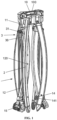
FIG. 1 is a schematic perspective view when the present disclosure is collapsed; -
FIG. 2 is a schematic perspective view when the present disclosure is expanded for a lying posture; -
FIG. 3 is a schematic perspective view when the present disclosure is expanded for a sitting posture; -
FIG. 4 is a partially enlarged view of A inFIG. 3 ; -
FIG. 5 is a partially enlarged view of B inFIG. 3 ; -
FIG. 6 is a schematic perspective view of a connecting head according to the present disclosure; and -
FIG. 7 is a schematic structural view after a hammock is provided according to the present disclosure. - In the figures:
1. coupling frame assembly, 10: base, 100: hand hole, 11: coupling rod, 110: locking hole, 12: coupling pipe, 120: adjusting hole, 13: locking member, 14: mounting sleeve, 140: mounting bolt, 141: hanging hole, 15: connecting head, 150: sleeve, 151: stabilizing member, 1510: limiting groove, 1511: mounting hole, 1512: clamping groove, 1513: lockup hole, 2: support leg, 3: linkage assembly, 30: inclined strut, and 31: connecting member. - In order to make the objectives, technical solutions, and advantages of the present disclosure clearer, the present disclosure is further described in detail below with reference to the accompanying drawings and embodiments. Understandably, the specific embodiments described herein are merely intended to explain the present disclosure but not to limit the present disclosure.
- Referring to
FIG. 1 to FIG. 7 , a hammock stand capable of being quickly collapsed and expanded includes coupling frame assembly 1, a plurality ofsupport legs 2, and a plurality oflinkage assemblies 3. The coupling frame assembly 1 includesbase 10, twocoupling rods 11, and twocoupling pipes 12. Lower ends of thecoupling rods 11 are respectively rotatably provided at two sides of thebase 10. Lower ends of thecoupling pipes 12 are respectively slidably sleeved on thecoupling rods 11. Thesupport legs 2 are respectively provided at two sides of a lower portion of each of thecoupling rods 11. Thesupport legs 2 each include an upper end hinged with thebase 10, and a lower end extending to the ground. Thelinkage assemblies 3 each include a plurality ofinclined struts 30. An upper end and a lower end of each of theinclined struts 30 are respectively rotatably connected to thecoupling rod 11 and thesupport leg 2 through connectingmember 31. Each of thecoupling pipe 12 is locked with thecoupling rod 11 throughlocking member 13. Through locking or unlocking of thelocking member 13, the hammock stand is expanded or collapsed. - As shown in
FIG. 2 and FIG. 3 , a plurality of lockingholes 110 are alternately formed along a length direction of thecoupling rod 11. The lockingmember 13 passes through thecoupling pipe 12, with a lower end threadedly connected to each of the locking holes 110, thereby locking thecoupling pipe 12 to thecoupling rod 11. By adjusting mounting angles of the twocoupling rods 11, a lying posture or a sitting posture of a hammock is switched. - As shown in
FIG. 1 ,FIG. 2 ,FIG. 3 ,FIG. 5 ,FIG. 6 andFIG. 7 , mountingsleeve 14 is sleeved on thecoupling pipe 12. A plurality of adjustingholes 120 are alternately formed in thecoupling pipe 12 from top to bottom. Mountingbolt 140 passes through the mountingsleeve 14, with an inner end threadedly connected to each of the adjustingholes 120, thereby locking the mountingsleeve 14 to thecoupling pipe 12. Hanginghole 141 for hanging a hammock is formed in the mountingsleeve 14. - As shown in
FIG. 1 ,FIG. 2 ,FIG. 3 andFIG. 5 , the connectingmember 31 is a U-shaped buckle. The end of theinclined strut 30 is rotatably connected to two winged edges of the U-shaped buckle. A bottom of the U-shaped buckle at the upper end of the inclined strut is rotatably connected to a sidewall of thecoupling pipe 12. A bottom of the U-shaped buckle at the lower end of the inclined strut is rotatably connected to a sidewall of thesupport leg 2. - As shown in
FIG. 2, FIG. 3 andFIG. 6 , an upper end of thecoupling pipe 12 is provided with connectinghead 15. The connectinghead 15 includessleeve 150 and two stabilizingmembers 151 provided oppositely at two sides of thesleeve 150. Thesleeve 150 is fixed at an upper end of thecoupling pipe 12 in a sleeving manner. A lower end of each of the stabilizingmembers 151 is fixedly connected to thesleeve 150. Limitinggroove 1510 is formed between the two stabilizingmembers 151. - As shown in
FIG. 2, FIG. 3 andFIG. 6 , mountinghole 1511 intersecting and communicating with the limitinggroove 1510 is formed in the stabilizingmember 151. - As shown in
FIG. 2, FIG. 3 andFIG. 6 , clampinggroove 1512 is formed outside the stabilizingmember 151. A plurality oflockup holes 1513 communicating with the clampinggroove 1512 are alternately formed in the stabilizingmember 151 from top to bottom. - As shown in
FIG. 1 ,FIG. 2 ,FIG. 3 ,FIG. 4 andFIG. 7 ,hand hole 100 is formed in an upper end of thebase 10. - As shown in
FIG. 1 ,FIG. 2 ,FIG. 3 ,FIG. 4 andFIG. 7 , there are foursupport legs 2 and fourinclined struts 30; and thecoupling pipe 12 is supported by two of thesupport legs 2 and two of the inclined struts 30. - The above are merely preferred specific implementations of the present disclosure, but the protection scope of the present disclosure is not limited thereto. Any modification or replacement easily conceived by those skilled in the art within the technical scope of the present disclosure should fall within the protection scope of the present disclosure. Therefore, the protection scope of the present disclosure should be subject to the protection scope of the claims.
Claims (9)
- A hammock stand capable of being quickly collapsed and expanded, comprising a coupling frame assembly, a plurality of support legs, and a plurality of linkage assemblies, wherein the coupling frame assembly comprises a base, two coupling rods, and two coupling pipes; lower ends of the coupling rods are respectively rotatably provided at two sides of the base; lower ends of the coupling pipes are respectively slidably sleeved on the coupling rods; the support legs are respectively provided at two sides of a lower portion of each of the coupling rods; the support legs each comprise an upper end hinged with the base, and a lower end extending to the ground; the linkage assemblies each comprise a plurality of inclined struts; an upper end and a lower end of each of the inclined struts are respectively rotatably connected to the coupling rod and the support leg through a connecting member; each of the coupling pipes is locked with the coupling rod through a locking member; and through locking or unlocking of the locking member, the hammock stand is expanded or collapsed.
- The hammock stand capable of being quickly collapsed and expanded according to claim 1, wherein a plurality of locking holes are alternately formed along a length direction of the coupling rod; the locking member passes through the coupling pipe, with a lower end threadedly connected to each of the locking holes, thereby locking the coupling pipe to the coupling rod; and by adjusting mounting angles of the two coupling rods, a lying posture or a sitting posture of a hammock is switched.
- The hammock stand capable of being quickly collapsed and expanded according to claim 1, wherein a mounting sleeve is sleeved on the coupling pipe; a plurality of adjusting holes are alternately formed in the coupling pipe from top to bottom; a mounting bolt passes through the mounting sleeve, with an inner end threadedly connected to each of the adjusting holes, thereby locking the mounting sleeve to the coupling pipe; and a hanging hole for hanging a hammock is formed in the mounting sleeve.
- The hammock stand capable of being quickly collapsed and expanded according to claim 1, wherein the connecting member is a U-shaped buckle; the end of the inclined strut is rotatably connected to two winged edges of the U-shaped buckle; a bottom of the U-shaped buckle at the upper end of the inclined strut is rotatably connected to a sidewall of the coupling pipe; and a bottom of the U-shaped buckle at the lower end of the inclined strut is rotatably connected to a sidewall of the support leg.
- The hammock stand capable of being quickly collapsed and expanded according to claim 1, wherein an upper end of the coupling pipe is provided with a connecting head; the connecting head comprises a sleeve and two stabilizing members provided oppositely at two sides of the sleeve; the sleeve is fixed at an upper end of the coupling pipe in a sleeving manner; a lower end of each of the stabilizing members is fixedly connected to the sleeve; and a limiting groove is formed between the two stabilizing members.
- The hammock stand capable of being quickly collapsed and expanded according to claim 5, wherein a mounting hole intersecting and communicating with the limiting groove is formed in the stabilizing member.
- The hammock stand capable of being quickly collapsed and expanded according to claim 6, wherein a clamping groove is formed outside the stabilizing member; and a plurality of lockup holes communicating with the clamping groove are alternately formed in the stabilizing member from top to bottom.
- The hammock stand capable of being quickly collapsed and expanded according to claim 1, wherein a hand hole is formed in an upper end of the base.
- The hammock stand capable of being quickly collapsed and expanded according to claim 1, wherein there are four support legs and four inclined struts; and the coupling pipe is supported by two of the support legs and two of the inclined struts.
Applications Claiming Priority (3)
| Application Number | Priority Date | Filing Date | Title |
|---|---|---|---|
| CN202211274645.5A CN115486630B (en) | 2022-10-18 | 2022-10-18 | Hammock support that swiftly receive and take |
| CN202222741060.1U CN218246163U (en) | 2022-10-18 | 2022-10-18 | Hammock support capable of being quickly folded |
| PCT/CN2022/130228 WO2024082351A1 (en) | 2022-10-18 | 2022-11-07 | Hammock support capable of being quickly folded and unfolded |
Publications (1)
| Publication Number | Publication Date |
|---|---|
| EP4381997A1 true EP4381997A1 (en) | 2024-06-12 |
Family
ID=90728601
Family Applications (1)
| Application Number | Title | Priority Date | Filing Date |
|---|---|---|---|
| EP22945118.2A Pending EP4381997A1 (en) | 2022-10-18 | 2022-11-07 | Hammock support capable of being quickly folded and unfolded |
Country Status (4)
| Country | Link |
|---|---|
| EP (1) | EP4381997A1 (en) |
| KR (1) | KR20240073908A (en) |
| AU (1) | AU2022463052A1 (en) |
| CA (1) | CA3223756A1 (en) |
-
2022
- 2022-11-07 EP EP22945118.2A patent/EP4381997A1/en active Pending
- 2022-11-07 CA CA3223756A patent/CA3223756A1/en active Pending
- 2022-11-07 AU AU2022463052A patent/AU2022463052A1/en active Pending
- 2022-11-07 KR KR1020247013236A patent/KR20240073908A/en active Search and Examination
Also Published As
| Publication number | Publication date |
|---|---|
| CA3223756A1 (en) | 2024-04-18 |
| AU2022463052A1 (en) | 2024-05-02 |
| KR20240073908A (en) | 2024-05-27 |
Similar Documents
| Publication | Publication Date | Title |
|---|---|---|
| US4934638A (en) | Collapsible tripod stool | |
| US5287872A (en) | Portable umbrella shelter | |
| US6505565B1 (en) | Collapsible table with elastic retaining elements | |
| US9591924B1 (en) | Multiple use device | |
| US12004636B2 (en) | Portable self-standing hammock frame with shortened hammock and method for suspending shortened hammock on a frame | |
| US20150282626A1 (en) | Portable seat awning | |
| US8141944B2 (en) | Collapsible chair having reduced linkages | |
| US5489052A (en) | Backpack frame convertible to a mattress supporting cot with a tent supporting structure | |
| US20050060802A1 (en) | Portable hammock | |
| CN218246163U (en) | Hammock support capable of being quickly folded | |
| EP4381997A1 (en) | Hammock support capable of being quickly folded and unfolded | |
| WO2024082351A1 (en) | Hammock support capable of being quickly folded and unfolded | |
| CN115486630B (en) | Hammock support that swiftly receive and take | |
| US20040140332A1 (en) | Backpack frame convertible to an adjustable mattress supporting cot with a tent supporting structure | |
| CN217959152U (en) | Novel connector and portable hammock adopting same | |
| CN215251822U (en) | Multifunctional airing device | |
| CN216453856U (en) | Multifunctional hammock support convenient to store | |
| KR101681408B1 (en) | Hammock cradle | |
| RU2493758C1 (en) | "comfort" beach umbrella | |
| RU2020849C1 (en) | Convertible collapsible seat-table | |
| TWM577442U (en) | Improved fixing structure of quick combination canopy | |
| JPH0713536Y2 (en) | Outdoor stand | |
| TWM567288U (en) | Improved fixing structure of quick combination canopy | |
| KR19980038784U (en) | Folding Fishing Tent |
Legal Events
| Date | Code | Title | Description |
|---|---|---|---|
| STAA | Information on the status of an ep patent application or granted ep patent |
Free format text: STATUS: UNKNOWN |
|
| STAA | Information on the status of an ep patent application or granted ep patent |
Free format text: STATUS: THE INTERNATIONAL PUBLICATION HAS BEEN MADE |
|
| PUAI | Public reference made under article 153(3) epc to a published international application that has entered the european phase |
Free format text: ORIGINAL CODE: 0009012 |
|
| STAA | Information on the status of an ep patent application or granted ep patent |
Free format text: STATUS: REQUEST FOR EXAMINATION WAS MADE |
|
| 17P | Request for examination filed |
Effective date: 20231214 |
|
| AK | Designated contracting states |
Kind code of ref document: A1 Designated state(s): AL AT BE BG CH CY CZ DE DK EE ES FI FR GB GR HR HU IE IS IT LI LT LU LV MC ME MK MT NL NO PL PT RO RS SE SI SK SM TR |