EP4381872B1 - Verfahren zur verwaltung von überschreibungen der halbstatischen planungsgelegenheiten für vollduplexkommunikation - Google Patents
Verfahren zur verwaltung von überschreibungen der halbstatischen planungsgelegenheiten für vollduplexkommunikation Download PDFInfo
- Publication number
- EP4381872B1 EP4381872B1 EP22740720.2A EP22740720A EP4381872B1 EP 4381872 B1 EP4381872 B1 EP 4381872B1 EP 22740720 A EP22740720 A EP 22740720A EP 4381872 B1 EP4381872 B1 EP 4381872B1
- Authority
- EP
- European Patent Office
- Prior art keywords
- transmission
- occasion
- downlink
- uplink
- sps
- Prior art date
- Legal status (The legal status is an assumption and is not a legal conclusion. Google has not performed a legal analysis and makes no representation as to the accuracy of the status listed.)
- Active
Links
Images


Classifications
-
- H—ELECTRICITY
- H04—ELECTRIC COMMUNICATION TECHNIQUE
- H04W—WIRELESS COMMUNICATION NETWORKS
- H04W72/00—Local resource management
- H04W72/50—Allocation or scheduling criteria for wireless resources
- H04W72/56—Allocation or scheduling criteria for wireless resources based on priority criteria
- H04W72/566—Allocation or scheduling criteria for wireless resources based on priority criteria of the information or information source or recipient
- H04W72/569—Allocation or scheduling criteria for wireless resources based on priority criteria of the information or information source or recipient of the traffic information
-
- H—ELECTRICITY
- H04—ELECTRIC COMMUNICATION TECHNIQUE
- H04W—WIRELESS COMMUNICATION NETWORKS
- H04W72/00—Local resource management
- H04W72/20—Control channels or signalling for resource management
- H04W72/23—Control channels or signalling for resource management in the downlink direction of a wireless link, i.e. towards a terminal
-
- H—ELECTRICITY
- H04—ELECTRIC COMMUNICATION TECHNIQUE
- H04W—WIRELESS COMMUNICATION NETWORKS
- H04W72/00—Local resource management
- H04W72/20—Control channels or signalling for resource management
-
- H—ELECTRICITY
- H04—ELECTRIC COMMUNICATION TECHNIQUE
- H04W—WIRELESS COMMUNICATION NETWORKS
- H04W72/00—Local resource management
- H04W72/12—Wireless traffic scheduling
- H04W72/1263—Mapping of traffic onto schedule, e.g. scheduled allocation or multiplexing of flows
- H04W72/1268—Mapping of traffic onto schedule, e.g. scheduled allocation or multiplexing of flows of uplink data flows
Definitions
- aspects of the present disclosure relate to wireless communications, and more particularly, to techniques for managing scenarios during full duplex communication in which a scheduling occasion becomes overwritten by a dynamic grant (DG).
- DG dynamic grant
- Wireless communication systems are widely deployed to provide various telecommunication services such as telephony, video, data, messaging, broadcasts, or other similar types of services.
- These wireless communication systems may employ multiple-access technologies capable of supporting communication with multiple users by sharing available system resources with those users (e.g., bandwidth, transmit power, or other resources).
- Multiple-access technologies can rely on any of code division, time division, frequency division orthogonal frequency division, single-carrier frequency division, or time division synchronous code division, to name a few.
- These and other multiple access technologies have been adopted in various telecommunication standards to provide a common protocol that enables different wireless devices to communicate on a municipal, national, regional, and even global level.
- wireless communication systems have made great technological advancements over many years, challenges still exist. For example, complex and dynamic environments can still attenuate or block signals between wireless transmitters and wireless receivers, undermining various established wireless channel measuring and reporting mechanisms, which are used to manage and optimize the use of finite wireless channel resources. Consequently, there exists a need for further improvements in wireless communications systems to overcome various challenges.
- United States Patent Application Publication No. US 2021/068106 relates to decoding of semi-persistent scheduling occasions.
- the invention is defined by the subject-matter of the independent claims. Preferred embodiments are defined in the dependent claims. Certain aspects, within the scope of the claims, can be implemented in a method for wireless communication performed by a user equipment (UE).
- the method includes receiving a first control message from a base station (BS), activating a first semi-static scheduling configuration and a second semi-static scheduling configuration for full duplex communication.
- the first semi-static scheduling configuration comprises at least one semi-persistent scheduling (SPS) occasion in which the UE is scheduled to receive a downlink transmission from the BS.
- SPS semi-persistent scheduling
- the second semi-static scheduling configuration comprises at least one configured grant (CG) occasion in which the UE is scheduled to transmit an uplink transmission to the BS, wherein the at least one CG occasion at least partially overlaps in time with the at least one SPS occasion.
- the method further includes receiving a second control message comprising a dynamic grant that schedules a transmission associated with the UE that overwrites at least one of the downlink transmission in the at least one SPS occasion or the uplink transmission in the at least one CG occasion and taking one or more actions, based on the dynamic grant, to communicate, with the BS, at least the transmission that overwrites the at least one of the downlink transmission in the at least one SPS occasion or the uplink transmission in the at least one CG occasion.
- CG configured grant
- the apparatus includes a memory comprising executable instructions and one or more processors configured to execute the executable instructions and cause the apparatus to: receive a first control message from a base station (BS), activating a first semi-static scheduling configuration and a second semi-static scheduling configuration for full duplex communication.
- the first semi-static scheduling configuration comprises at least one semi-persistent scheduling (SPS) occasion in which the apparatus is scheduled to receive a downlink transmission from the BS.
- SPS semi-persistent scheduling
- the second semi-static scheduling configuration comprises at least one configured grant (CG) occasion in which the apparatus is scheduled to transmit an uplink transmission to the BS, wherein the at least one CG occasion at least partially overlaps in time with the at least one SPS occasion.
- CG configured grant
- the one or more processors may be configured to cause the apparatus to receive a second control message comprising a dynamic grant that schedules a transmission associated with the apparatus that overwrites at least one of the downlink transmission in the at least one SPS occasion or the uplink transmission in the at least one CG occasion and take one or more actions, based on the dynamic grant, to communicate, with the BS, at least the transmission that overwrites the at least one of the downlink transmission in the at least one SPS occasion or the uplink transmission in the at least one CG occasion.
- a second control message comprising a dynamic grant that schedules a transmission associated with the apparatus that overwrites at least one of the downlink transmission in the at least one SPS occasion or the uplink transmission in the at least one CG occasion and take one or more actions, based on the dynamic grant, to communicate, with the BS, at least the transmission that overwrites the at least one of the downlink transmission in the at least one SPS occasion or the uplink transmission in the at least one CG occasion.
- the apparatus includes means for receiving a first control message from a base station (BS), activating a first semi-static scheduling configuration and a second semi-static scheduling configuration for full duplex communication.
- the first semi-static scheduling configuration comprises at least one semi-persistent scheduling (SPS) occasion in which the apparatus is scheduled to receive a downlink transmission from the BS.
- the second semi-static scheduling configuration comprises at least one configured grant (CG) occasion in which the apparatus is scheduled to transmit an uplink transmission to the BS, wherein the at least one CG occasion at least partially overlaps in time with the at least one SPS occasion.
- SPS semi-persistent scheduling
- CG configured grant
- the apparatus further includes means for receiving a second control message comprising a dynamic grant that schedules a transmission associated with the apparatus that overwrites at least one of the downlink transmission in the at least one SPS occasion or the uplink transmission in the at least one CG occasion and means for taking one or more actions, based on the dynamic grant, to communicate, with the BS, at least the transmission that overwrites the at least one of the downlink transmission in the at least one SPS occasion or the uplink transmission in the at least one CG occasion.
- a second control message comprising a dynamic grant that schedules a transmission associated with the apparatus that overwrites at least one of the downlink transmission in the at least one SPS occasion or the uplink transmission in the at least one CG occasion and means for taking one or more actions, based on the dynamic grant, to communicate, with the BS, at least the transmission that overwrites the at least one of the downlink transmission in the at least one SPS occasion or the uplink transmission in the at least one CG occasion.
- the non-transitory computer-readable medium comprises executable instructions that, when executed by one or more processors of an apparatus, cause the apparatus to: receive a first control message from a base station (BS), activating a first semi-static scheduling configuration and a second semi-static scheduling configuration for full duplex communication.
- the first semi-static scheduling configuration comprises at least one semi-persistent scheduling (SPS) occasion in which the apparatus is scheduled to receive a downlink transmission from the BS.
- SPS semi-persistent scheduling
- the second semi-static scheduling configuration comprises at least one configured grant (CG) occasion in which the apparatus is scheduled to transmit an uplink transmission to the BS, wherein the at least one CG occasion at least partially overlaps in time with the at least one SPS occasion.
- CG configured grant
- non-transitory computer-readable medium may include executable instructions that, when executed by the one or more processors of the apparatus, cause the apparatus to receive a second control message comprising a dynamic grant that schedules a transmission associated with the apparatus that overwrites at least one of the downlink transmission in the at least one SPS occasion or the uplink transmission in the at least one CG occasion and to take one or more actions, based on the dynamic grant, to communicate, with the BS, at least the transmission that overwrites the at least one of the downlink transmission in the at least one SPS occasion or the uplink transmission in the at least one CG occasion.
- the computer program product may be embodied on a computer-readable storage medium and may comprise code for: receiving a first control message from a base station (BS), activating a first semi-static scheduling configuration and a second semi-static scheduling configuration for full duplex communication.
- the first semi-static scheduling configuration comprises at least one semi-persistent scheduling (SPS) occasion in which the UE is scheduled to receive a downlink transmission from the BS.
- SPS semi-persistent scheduling
- the second semi-static scheduling configuration comprises at least one configured grant (CG) occasion in which the UE is scheduled to transmit an uplink transmission to the BS, wherein the at least one CG occasion at least partially overlaps in time with the at least one SPS occasion.
- CG configured grant
- the computer program product may further comprise code for receiving a second control message comprising a dynamic grant that schedules a transmission associated with the UE that overwrites at least one of the downlink transmission in the at least one SPS occasion or the uplink transmission in the at least one CG occasion and code for taking one or more actions, based on the dynamic grant, to communicate, with the BS, at least the transmission that overwrites the at least one of the downlink transmission in the at least one SPS occasion or the uplink transmission in the at least one CG occasion.
- the method generally includes transmitting a first control message to a user equipment (UE), activating a first semi-static scheduling configuration and a second semi-static scheduling configuration for full duplex communication.
- the first semi-static scheduling configuration comprises at least one semi-persistent scheduling (SPS) occasion in which the UE is scheduled to receive a downlink transmission from the BS.
- the second semi-static scheduling configuration comprises at least one configured grant (CG) occasion in which the UE is scheduled to transmit an uplink transmission to the BS, wherein the at least one CG occasion at least partially overlaps in time with the at least one SPS occasion.
- SPS semi-persistent scheduling
- CG configured grant
- the method may further include transmitting a second control message comprising a dynamic grant that schedules a transmission associated with the UE that overwrites at least one of the downlink transmission in the at least one SPS occasion or the uplink transmission in the at least one CG occasion and communicating, based on the dynamic grant, at least the transmission that overwrites the at least one of the downlink transmission in the at least one SPS occasion or the uplink transmission in the at least one CG occasion with the UE.
- a second control message comprising a dynamic grant that schedules a transmission associated with the UE that overwrites at least one of the downlink transmission in the at least one SPS occasion or the uplink transmission in the at least one CG occasion and communicating, based on the dynamic grant, at least the transmission that overwrites the at least one of the downlink transmission in the at least one SPS occasion or the uplink transmission in the at least one CG occasion with the UE.
- the apparatus includes a memory comprising executable instructions and one or more processors configured to execute the executable instructions and cause the apparatus to: transmit a first control message to a user equipment (UE), activating a first semi-static scheduling configuration and a second semi-static scheduling configuration for full duplex communication.
- the first semi-static scheduling configuration comprises at least one semi-persistent scheduling (SPS) occasion in which the UE is scheduled to receive a downlink transmission from the apparatus.
- SPS semi-persistent scheduling
- the second semi-static scheduling configuration comprises at least one configured grant (CG) occasion in which the UE is scheduled to transmit an uplink transmission to the apparatus, wherein the at least one CG occasion at least partially overlaps in time with the at least one SPS occasion.
- the one or more processor may be configured to cause the apparatus to transmit a second control message comprising a dynamic grant that schedules a transmission associated with the UE that overwrites at least one of the downlink transmission in the at least one SPS occasion or the uplink transmission in the at least one CG occasion and communicate, based on the dynamic grant, at least the transmission that overwrites the at least one of the downlink transmission in the at least one SPS occasion or the uplink transmission in the at least one CG occasion with the UE.
- CG configured grant
- the apparatus includes means for transmitting a first control message to a user equipment (UE), activating a first semi-static scheduling configuration and a second semi-static scheduling configuration for full duplex communication.
- the first semi-static scheduling configuration comprises at least one semi-persistent scheduling (SPS) occasion in which the UE is scheduled to receive a downlink transmission from the BS.
- the second semi-static scheduling configuration comprises at least one configured grant (CG) occasion in which the UE is scheduled to transmit an uplink transmission to the BS, wherein the at least one CG occasion at least partially overlaps in time with the at least one SPS occasion.
- SPS semi-persistent scheduling
- CG configured grant
- the apparatus may further include means for transmitting a second control message comprising a dynamic grant that schedules a transmission associated with the UE that overwrites at least one of the downlink transmission in the at least one SPS occasion or the uplink transmission in the at least one CG occasion and means for communicating, based on the dynamic grant, at least the transmission that overwrites the at least one of the downlink transmission in the at least one SPS occasion or the uplink transmission in the at least one CG occasion with the UE.
- a second control message comprising a dynamic grant that schedules a transmission associated with the UE that overwrites at least one of the downlink transmission in the at least one SPS occasion or the uplink transmission in the at least one CG occasion and means for communicating, based on the dynamic grant, at least the transmission that overwrites the at least one of the downlink transmission in the at least one SPS occasion or the uplink transmission in the at least one CG occasion with the UE.
- the non-transitory computer-readable medium comprises executable instructions that, when executed by one or more processors of an apparatus, cause the apparatus to: transmit a first control message to a user equipment (UE), activating a first semi-static scheduling configuration and a second semi-static scheduling configuration for full duplex communication.
- the first semi-static scheduling configuration comprises at least one semi-persistent scheduling (SPS) occasion in which the UE is scheduled to receive a downlink transmission from the BS.
- SPS semi-persistent scheduling
- the second semi-static scheduling configuration comprises at least one configured grant (CG) occasion in which the UE is scheduled to transmit an uplink transmission to the BS, wherein the at least one CG occasion at least partially overlaps in time with the at least one SPS occasion.
- CG configured grant
- non-transitory computer-readable medium comprises executable instructions that, when executed by the one or more processors of the apparatus, cause the apparatus to transmit a second control message comprising a dynamic grant that schedules a transmission associated with the UE that overwrites at least one of the downlink transmission in the at least one SPS occasion or the uplink transmission in the at least one CG occasion and to communicate, based on the dynamic grant, at least the transmission that overwrites the at least one of the downlink transmission in the at least one SPS occasion or the uplink transmission in the at least one CG occasion with the UE.
- the computer program product may be embodied on a computer-readable storage medium and may comprise code for: transmitting a first control message to a user equipment (UE), activating a first semi-static scheduling configuration and a second semi-static scheduling configuration for full duplex communication.
- the first semi-static scheduling configuration comprises at least one semi-persistent scheduling (SPS) occasion in which the UE is scheduled to receive a downlink transmission from the BS.
- SPS semi-persistent scheduling
- the second semi-static scheduling configuration comprises at least one configured grant (CG) occasion in which the UE is scheduled to transmit an uplink transmission to the BS, wherein the at least one CG occasion at least partially overlaps in time with the at least one SPS occasion.
- the computer program product may comprise code for transmitting a second control message comprising a dynamic grant that schedules a transmission associated with the UE that overwrites at least one of the downlink transmission in the at least one SPS occasion or the uplink transmission in the at least one CG occasion and code for communicating, based on the dynamic grant, at least the transmission that overwrites the at least one of the downlink transmission in the at least one SPS occasion or the uplink transmission in the at least one CG occasion with the UE
- Implementations may range in spectrum from chip-level or modular components to non-modular, non-chip-level implementations and further to aggregate, distributed, or OEM devices or systems incorporating one or more aspects of the described innovations.
- devices incorporating described aspects and features may also necessarily include additional components and features for implementation and practice of claimed and described embodiments.
- transmission and reception of wireless signals necessarily includes a number of components for analog and digital purposes (e.g., hardware components including antenna, RF-chains, power amplifiers, modulators, buffer, processor(s), interleaver, adders/summers, etc.).
- innovations described herein may be practiced in a wide variety of devices, chip-level components, systems, distributed arrangements, end-user devices, etc. of varying sizes, shapes, and constitution.
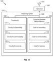
- aspects of the present disclosure provide apparatuses, methods, processing systems, and computer-readable mediums for communicating dynamically scheduled transmissions that overwrite transmissions in existing semi-statically configured scheduling occasions.
- certain wireless communications devices in a wireless communication network may be capable of full duplex communication with a base station (BS) using different antenna panels.
- the UE may use a first antenna panel to receive downlink transmissions from the BS while simultaneously using a second antenna panel to transmit uplink transmissions to the BS or another BS.
- the UE may be configured to perform the full duplex communication in one or more semi-statically configured scheduling occasions.
- the one or more semi-statically configured scheduling occasions may include at least one semi-persistent scheduling (SPS) occasion in which the UE is scheduled to receive a downlink transmission from the BS.
- SPS semi-persistent scheduling
- the one or more semi-statically configured scheduling occasions may also include at least one configured grant (CG) occasion in which the UE is scheduled to transmit an uplink transmission to the BS, wherein the at least one CG occasion at least partially overlaps in time with the at least one SPS occasion.
- CG configured grant
- the at least one SPS occasion and the at least one CG occasion may overlap in time and, thus, the UE may be configured to use full duplex communication to receive the downlink transmission in the at least one SPS occasion while simultaneously transmitting the uplink transmission in the at least one CG occasion. Further, to facilitate the full duplex communication, the UE may be configured with a downlink receive beam for receiving the downlink transmission in the at least one SPS grant that is compatible with an uplink transmit beam configured for transmitting the uplink transmission in the at least one CG grant. Compatibility between uplink transmit beams and downlink receive beams may be defined in terms of self-interference experienced by the UE.
- uplink transmit beams and downlink receive beams that are compatible with each other may be associated with a level of self-interference experienced by the UE below a self-interference threshold.
- an uplink transmit beam that is compatible with a downlink receive beam is a beam that, when used for transmitting an uplink transmission simultaneously with receiving a downlink transmission, causes an amount of self-interference to the downlink receive beam that is less than the self-interference threshold.
- these beams may be considered incompatible.
- the UE may generally be configured with compatible downlink receive beams and uplink transmit beams for receiving downlink transmissions in the at least one SPS occasion and transmitting uplink transmissions in the at least one CG occasion, respectively
- the UE is dynamically scheduled by the BS to communicate a transmission that overwrites the at least one SPS occasion or the at least one CG occasion.
- the UE may be dynamically scheduled to receive a physical downlink shared channel (PDSCH) transmission that overwrites the at least one SPS occasion and that overlaps with the at least one CG occasion.
- PDSCH physical downlink shared channel
- PUSCH physical uplink shared channel
- the UE is configured to communicate the dynamically scheduled transmission using a beam that is incompatible with the overlapped scheduling occasion. For example, there may be cases in which the UE is configured to receive the dynamically scheduled PDSCH transmission using a downlink receive beam that is incompatible with the uplink transmit beam used for transmitting the uplink transmission in the at least one CG occasion that overlaps in time with the PDSCH transmission. Likewise, there may be cases in which the UE is configured to transmit the dynamically scheduled PUSCH transmission using an uplink transmit beam that is incompatible with the downlink receive beam used for receiving the downlink transmission in the at least one SPS occasion that overlaps in time with the PUSCH transmission.
- aspects of the present disclosure provide techniques to help reduce self-interference experienced by wireless communications devices that are capable of FD communication.
- such techniques may include a UE reporting, to a BS, antenna panel information indicating one or more pairs of antenna panels that are capable of FD communication.
- the one or more pairs of antenna panels that are capable of the FD communication may include pairs of antenna panels that do not (or minimally) interfere with each other.
- the UE may then be configured with at least one of these pairs of antenna panels, thereby reducing self-interference when performing the FD communication and helping to alleviate the negative effects described above.
- aspects of the present disclosure provide techniques for managing scenarios during full duplex communication in which a scheduling occasion becomes overwritten by a dynamic grant.
- the techniques presented may be used by a UE to determine whether or not to proceed with communicating a transmission in a first scheduling occasion using a beam that conflicts with a beam used for communicating a dynamically scheduled transmission in an overwritten scheduling occasion that overlaps with the first scheduling occasion.
- FIG. 1 depicts an example of a wireless communication network 100, in which aspects described herein may be implemented.
- wireless communication network 100 includes base stations (BSs) 102, user equipments (UEs) 104, one or more core networks, such as an Evolved Packet Core (EPC) 160 and 5G Core (5GC) network 190, which interoperate to provide wireless communications services.
- EPC Evolved Packet Core
- 5GC 5G Core
- Base stations 102 may provide an access point to the EPC 160 and/or 5GC 190 for a user equipment 104, and may perform one or more of the following functions: transfer of user data, radio channel ciphering and deciphering, integrity protection, header compression, mobility control functions (e.g., handover, dual connectivity), inter-cell interference coordination, connection setup and release, load balancing, distribution for non-access stratum (NAS) messages, NAS node selection, synchronization, radio access network (RAN) sharing, multimedia broadcast multicast service (MBMS), subscriber and equipment trace, RAN information management (RIM), paging, positioning, delivery of warning messages, among other functions.
- NAS non-access stratum
- RAN radio access network
- MBMS multimedia broadcast multicast service
- RIM RAN information management
- Base stations may include and/or be referred to as a gNB, NodeB, eNB, ng-eNB (e.g., an eNB that has been enhanced to provide connection to both EPC 160 and 5GC 190), an access point, a base transceiver station, a radio base station, a radio transceiver, or a transceiver function, or a transmission reception point in various contexts.
- a gNB NodeB
- eNB e.g., an eNB that has been enhanced to provide connection to both EPC 160 and 5GC 190
- an access point e.g., an eNB that has been enhanced to provide connection to both EPC 160 and 5GC 190
- a base transceiver station e.g., a radio base station, a radio transceiver, or a transceiver function, or a transmission reception point in various contexts.
- Base stations 102 wirelessly communicate with UEs 104 via communications links 120. Each of base stations 102 may provide communication coverage for a respective geographic coverage area 110, which may overlap in some cases. For example, small cell 102' (e.g., a low-power base station) may have a coverage area 110' that overlaps the coverage area 110 of one or more macrocells (e.g., high-power base stations).
- small cell 102' e.g., a low-power base station
- macrocells e.g., high-power base stations
- the communication links 120 between base stations 102 and UEs 104 may include uplink (UL) (also referred to as reverse link) transmissions from a user equipment 104 to a base station 102 and/or downlink (DL) (also referred to as forward link) transmissions from a base station 102 to a user equipment 104.
- UL uplink
- DL downlink
- the communication links 120 may use multiple-input and multiple-output (MIMO) antenna technology, including spatial multiplexing, beamforming, and/or transmit diversity in various aspects.
- MIMO multiple-input and multiple-output
- Examples of UEs 104 include a cellular phone, a smart phone, a session initiation protocol (SIP) phone, a laptop, a personal digital assistant (PDA), a satellite radio, a global positioning system, a multimedia device, a video device, a digital audio player, a camera, a game console, a tablet, a smart device, a wearable device, a vehicle, an electric meter, a gas pump, a large or small kitchen appliance, a healthcare device, an implant, a sensor/actuator, a display, or other similar devices.
- SIP session initiation protocol
- PDA personal digital assistant
- UEs 104 may be internet of things (IoT) devices (e.g., parking meter, gas pump, toaster, vehicles, heart monitor, or other IoT devices), always on (AON) devices, or edge processing devices.
- IoT internet of things
- UEs 104 may also be referred to more generally as a station, a mobile station, a subscriber station, a mobile unit, a subscriber unit, a wireless unit, a remote unit, a mobile device, a wireless device, a wireless communications device, a remote device, a mobile subscriber station, an access terminal, a mobile terminal, a wireless terminal, a remote terminal, a handset, a user agent, a mobile client, or a client.
- base stations may utilize beamforming 182 with a UE 104 to improve path loss and range.
- base station 180 and the UE 104 may each include a plurality of antennas, such as antenna elements, antenna panels, and/or antenna arrays to facilitate the beamforming.
- base station 180 may transmit a beamformed signal to UE 104 in one or more transmit directions 182'.
- UE 104 may receive the beamformed signal from the base station 180 in one or more receive directions 182".
- UE 104 may also transmit a beamformed signal to the base station 180 in one or more transmit directions 182''.
- Base station 180 may also receive the beamformed signal from UE 104 in one or more receive directions 182'.
- Base station 180 and UE 104 may then perform beam training to determine the best receive and transmit directions for each of base station 180 and UE 104.
- the transmit and receive directions for base station 180 may or may not be the same.
- the transmit and receive directions for UE 104 may or may not be the same.
- Wireless communication network 100 includes full-duplex (FD) communication component 199, which may be configured to perform the operations illustrated in one or more of FIGs. 9-10 , as well as other operations described herein for communicating dynamically scheduled transmissions that overwrite transmissions in existing semi-statically configured scheduling occasions.
- Wireless communication network 100 further includes FD communication component 198, which may be configured to perform the operations illustrated in one or more of FIGs. 9 or 11 , as well as other operations described herein for communicating dynamically scheduled transmissions that overwrite transmissions in existing semi-statically configured scheduling occasions.
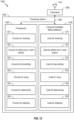
- FIG. 2 depicts aspects of an example base station (BS) 102 and a user equipment (UE) 104.
- BS base station
- UE user equipment
- base station 102 includes various processors (e.g., 220, 230, 238, and 240), antennas 234a-t (collectively 234), transceivers 232a-t (collectively 232), which include modulators and demodulators, and other aspects, which enable wireless transmission of data (e.g., data source 212) and wireless reception of data (e.g., data sink 239).
- base station 102 may send and receive data between itself and user equipment 104.
- Base station 102 includes controller/processor 240, which may be configured to implement various functions related to wireless communications.
- controller/processor 240 includes FD communication component 241, which may be representative of FD communication component 199 of FIG. 1 .
- FD communication component 241 may be implemented additionally or alternatively in various other aspects of base station 102 in other implementations.
- user equipment 104 includes various processors (e.g., 258, 264, 266, and 280), antennas 252a-r (collectively 252), transceivers 254a-r (collectively 254), which include modulators and demodulators, and other aspects, which enable wireless transmission of data (e.g., data source 262) and wireless reception of data (e.g., data sink 260).
- processors e.g., 258, 264, 266, and 280
- antennas 252a-r collectively 252
- transceivers 254a-r collectively 254
- other aspects which enable wireless transmission of data (e.g., data source 262) and wireless reception of data (e.g., data sink 260).
- User equipment 104 includes controller/processor 280, which may be configured to implement various functions related to wireless communications.
- controller/processor 280 includes FD communication component 281, which may be representative of FD communication component 198 of FIG. 1 .
- FD communication component 281 may be implemented additionally or alternatively in various other aspects of user equipment 104 in other implementations.
- FIGS. 3A-3D depict aspects of data structures for a wireless communication network, such as wireless communication network 100 of FIG. 1 .
- FIG. 3A is a diagram 300 illustrating an example of a first subframe within a 5G (e.g., 5G NR) frame structure
- FIG. 3B is a diagram 330 illustrating an example of DL channels within a 5G subframe
- FIG. 3C is a diagram 350 illustrating an example of a second subframe within a 5G frame structure
- FIG. 3D is a diagram 380 illustrating an example of UL channels within a 5G subframe.
- FIG. 1 Further discussions regarding FIG. 1 , FIG. 2 , and FIGS. 3A -3D are provided later in this disclosure.
- an electromagnetic spectrum is often subdivided into various classes, bands, channels, or other features.
- the subdivision is often provided based on wavelength and frequency, where frequency may also be referred to as a carrier, a subcarrier, a frequency channel, a tone, or a subband.
- 5G networks may utilize several frequency ranges, which in some cases are defined by a standard, such as the 3GPP standards.
- 3GPP technical standard TS 38.101 currently defines Frequency Range 1 (FR1) as including 600 MHz - 6 GHz, though specific uplink and downlink allocations may fall outside of this general range.
- FR1 is often referred to (interchangeably) as a "Sub-6 GHz" band.
- FR2 Frequency Range 2
- FR2 is sometimes referred to (interchangeably) as a “millimeter wave” (“mmW” or “mmWave”) band, despite being different from the extremely high frequency (EHF) band (30 GHz - 300 GHz) that is identified by the International Telecommunications Union (ITU) as a "millimeter wave” band because wavelengths at these frequencies are between 1 millimeter and 10 millimeters.
- EHF extremely high frequency
- mmWave / near mmWave radio frequency band may have higher path loss and a shorter range compared to lower frequency communications.
- a base station e.g., 180
- mmWave / near mmWave radio frequency bands may utilize beamforming (e.g., 182) with a UE (e.g., 104) to improve path loss and range.
- UEs and BSs may be able to transmit or receive transmissions using multiple antennas, beams, and/or antenna panels (e.g., antenna element arrays).
- An antenna panel may comprise a collection of transceiver units (TXRUs) that are capable of generating an analog beam.
- TXRUs transceiver units
- the one beam may correspond to two antenna ports.
- same sets or different sets of antenna panels can be used for DL reception and UL transmission.
- the same set of antenna panels may be used for both DL reception and UL transmission while in other cases different sets of antenna panels could be used for DL reception as compared to UL transmission.
- antenna panels can be associated with the same as well as different numbers of antenna ports, a number of beams, and/or an effective isotropic radiated power (EIRP). In some cases, while different antenna panels may share a same number of beams, there may not be beam correspondence across different antenna panels. Further, in some cases, each antenna panel may be associated with the same or independent operation parameters, such as power control (PC) parameters, a fast Fourier transform timing window, a time advance (TA) parameter, and the like. Additionally, each antenna panel of the UE may be associated with a particular panel identifier (ID) or an antenna panel group ID.
- PC power control
- TA time advance
- the antenna panel ID or antenna panel group ID may include one or more of a beam group ID, a transmission configuration indicator (TCI) state pool ID, a sounding reference signal (SRS) resource group ID, a control resource set (CORESET) pool ID, or a closed loop power control index.
- TCI transmission configuration indicator
- SRS sounding reference signal
- CORESET control resource set
- the capability to perform transmissions using multiple panels may be especially useful for higher frequency transmission, such as millimeter wave transmissions described above.
- the transmissions associated with a UE may be received from or transmitted to a serving BS or transmission reception point (TRP) via a Uu interface.
- TRP transmission reception point
- transmissions using multiple antenna panels may allow for increased throughput (e.g., by simultaneously or concurrently transmitting/receiving data to/from the BS using the multiple antenna panels) and/or increased reliability (e.g., by sending/receiving the same information using the multiple antenna panels).
- Such transmissions may be referred to as multi-panel transmissions.
- wireless communication devices such as UEs and BSs, may communicate using multiple antenna panels.
- the multiple antenna panels may be used for half-duplex (HD) communication, such as in current 5G new radio (NR) communication systems, in which downlink (DL) and uplink (UL) transmissions are transmitted non-simultaneously (e.g., transmitted in different time resources).
- HD communication may be considered baseline behavior in Release 15 (R-15) and 16 (R-16) of 5G NR.
- the use of multiple antenna panels may allow for full duplex (FD) communication whereby uplink (UL) and downlink (DL) transmissions may be performed simultaneously (e.g., in the same time resources).
- UL transmission by the UE may be performed on one panel while DL reception may be performed simultaneously on another panel of the UE.
- DL transmission by the BS may be performed on one antenna panel while UL reception may be performed on another antenna panel.
- FD capability may be conditioned on beam separation (e.g., frequency separation or spatial separation) and may still be subject to certain self-interference between UL and DL (e.g., UL transmission directly interferes with DL reception) as well as clutter echo (e.g., where UL transmission echoes affect UL transmission and/or DL reception).
- beam separation e.g., frequency separation or spatial separation
- clutter echo e.g., where UL transmission echoes affect UL transmission and/or DL reception.
- FD capability may be subject to certain interference
- FD capability provides for reduced transmission and reception latency (e.g., it may be possible to receive DL transmissions in an UL-only slot), increased spectrum efficiency (e.g., per cell and/or per UE), and more efficient resource utilization.
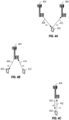
- FIGs. 4A-4C illustrates different FD use cases within a wireless communication network, such as the wireless communication network 100.
- FIG. 4A illustrates a first FD use case involving transmission between one UE 402 and two base stations (or multiple transmission reception points (mTRP)), BS 404 and BS 406.
- UE 402 may be representative of UE 104 of FIG. 1 and BSs 404, 406 may be representative of BS 102 of FIG. 1 .
- the UE 402 may simultaneously receive DL transmissions 408 from the BS 404 and transmit UL transmissions 410 to the BS 406.
- the DL transmissions 408 and UL transmissions 410 may be performed using different antenna panels to facilitate the simultaneous transmission and reception.
- a second FD use case is illustrated in FIG. 4B involving two different UEs and one BS.
- the UE 402 may receive DL transmissions 408 from the BS 404 while another UE 412 may simultaneously transmit UL transmission 410 to the BS 404.
- BS 404 is conducting simultaneous uplink and downlink communications.
- a third FD use case is illustrated in FIG. 4C involving one BS and one UE.
- the UE 402 may receive DL transmissions 408 from the BS 404 and may simultaneously transmit UL transmissions 410 to the BS 404.
- simultaneous reception/transmission by the UE 402 may be facilitated by different antenna panels.
- Table 1 illustrates various example scenarios in which each of the FD use cases may be used.
- Table 1 Base Station UE FD use case FD disabled FD disabled Baseline R-15/16 5G behavior FD disabled FD enabled Use case #1 ( Fig. 4A ) for mTRP FD enabled FD disabled Use case #2 ( Fig. 4B ) + R-16 IAB FD enabled FD enabled Use case #3 ( Fig. 4C )
- the baseline R-15 and R-16 5G behavior may be used (e.g., HD communication).
- the UE may operate according to the first example FD use case shown in FIG. 4A in which the UE may communicate with two different TRPs simultaneously (e.g., simultaneous UL and DL transmissions) using two different antenna panels.
- the BS may operate according to the second example FD use case shown in FIG.
- the BS and UE may operate according to the third example FD use case shown in FIG. 4C in which the BS and UE may communicate with each other simultaneously on the UL and DL, each of the BS and UE using different antenna panels for UL and DL transmissions.
- FD communication may be facilitated through the use of frequency division multiplexing (FDM) or spatial division multiplexing (SDM).
- FDM frequency division multiplexing
- SDM spatial division multiplexing
- the simultaneous UL and DL transmissions may be transmitted in the same time resources but on separate frequency bands separated by some guard band.
- SDM the simultaneous UL and DL transmissions may transmitted on the same time and frequency resources but spatially separated into different, directional transmission beams.
- TDM time division multiplexing
- FIG. 5 illustrates interference scenarios that may occur within a wireless communications network 500 in which FD and HD communications may be used.
- the wireless communications network 400 may be an example of the wireless communications network 100 of FIG. 1 .
- wireless communication may occur between a plurality of wireless communication devices, such as BS 502, BS 504, UE 506, and UE 508.
- BS 502 and UE 506 may be capable of FD communication while BS 504 and UE 508 may only be capable of HD communication.
- HD and FD communication may be intermixed in the wireless communication network 400.
- Such intermixed HD and FD communication may include communication between an FD UE and an HD BS (e.g., UE 506 and BS 504), between an FD BS and an HD UE (e.g., BS 502 and UE 508), and between an FD BS and an FD UE (e.g., BS 502 and UE 506).
- an FD UE and an HD BS e.g., UE 506 and BS 504
- an FD BS and an HD UE e.g., BS 502 and UE 508
- an FD BS and an FD UE e.g., BS 502 and UE 506
- wireless communications devices that are capable of using FD communication may be susceptible to interference from neighboring wireless communications devices.
- FD-capable UE 506 may be susceptible to interference from neighboring UE 508 as well as neighboring BS 504.
- FD-capable BS 502 may be susceptible to interference from neighboring BS 504.
- FD-capable BS 502 and FD-capable UE 506 may also be susceptible to self-interference between antenna panels used for FD communication.
- UE 506 may experience self-interference 510 between antenna panels used for FD communication with the BS 502 and/or BS 504. More specifically, for example, the UE 506 may experience self-interference 510 between an antenna panel used for receiving downlink transmissions from the BS 502 and an antenna panel used for transmitting uplink transmissions to the BS 502 and/or BS 504.
- the BS 502 may experience self-interference 512 between an antenna panel used for receiving uplink transmissions from the UE 506 and an antenna panel used for transmitting downlink transmissions the UE 506.
- This self-interference that may be experienced by wireless communications devices that are capable of FD communication is undesirable and can lead to negative effects.
- These negative effects may include transmissions that cannot be properly received or decoded, which may lead to wasted time and frequency resources within the wireless communication network 500, as well as wasted power resources at a transiting device and receiving device, associated with having to retransmit/re-receive the transmissions that were not previously properly received/decoded due to the self-interference between antenna panels.
- Wireless communications devices such as UEs capable of FD communication with a base station, may be scheduled to communicate (e.g., transmit and/or receive) transmissions in different manners.
- a first manner of scheduling UEs involves using a dynamic grant.
- the base station may transmit control information, such as downlink control information (DCI), which includes the dynamic grant.
- DCI downlink control information
- the dynamic grant may include an indication of one or more time and frequency resources for receiving a downlink transmission or transmitting an uplink transmission.
- the one or more time and frequency resources may be non-periodic and may be allocated to the UE for a particular uplink/downlink transmission.
- the base station may transmit another dynamic grant with additional scheduling information for this other transmission, which may increase overhead signaling.
- a semi-persistent scheduling (SPS) configuration may be used to schedule a UE with a periodic set of time and frequency resources, known as SPS occasions, for periodically receiving downlink transmissions, such as transmissions on physical downlink shared channel (PDSCH).
- SPS semi-persistent scheduling
- PDSCH physical downlink shared channel
- SPS was also used in long term evolution (LTE) for scheduling uplink transmissions for UEs, such as transmission of a physical uplink shared channel (PUSCH).
- LTE long term evolution
- PUSCH physical uplink shared channel
- the periodic set of time and frequency resources for SPS was usually dedicated to a single UE. As a result, if this single UE does not need certain resources in the periodic set of time and frequency resources for uplink transmissions, the resources that are unemployed by the UE were wasted. Accordingly, to reduce the waste of periodically allocated resources, Fifth Generation (5G) New Radio (NR) enables multiple UEs to share a periodic set of time and frequency resources, known a configured grant (CG) occasions or CG resources.
- 5G Fifth Generation
- NR enables multiple UEs to share a periodic set of time and frequency resources, known a configured grant (CG) occasions or CG resources.
- CG configured grant
- a base station transmit a CG configuration that allocates the CG occasions/resources to multiple UEs, and the UEs may randomly utilize the resources when they have data to transmit.
- the base station may eliminate packet transmission delay for a scheduling request procedure associated with scheduling uplink transmissions and increases a utilization ratio of allocated periodic time and frequency resources.
- SPS occasions in the set of SPS occasions 604 may overlaps with CG occasions in the set of CG occasions 606. For example, as pictured in FIG 6 , each SPS occasion of the set of SPS occasions 604 completely overlaps with a corresponding CG occasion in the set of CG occasions 606. As such, downlink transmissions within the set of SPS occasions 604 may be received simultaneously in time with uplink transmissions by the UE within the set of CG occasions 606, for example, using FD communication.
- the UE when performing full duplex communication to simultaneously receive downlink transmissions in SPS occasions and transmitting uplink transmissions in CG occasions, the UE may use a pair of compatible beams to receive the downlink transmissions and to transmit the uplink transmissions.
- the pair of compatible beams may include a downlink receive beam associated with a first antenna panel of the UE to receive the downlink transmissions and an uplink transmit beam associated with a second antenna panel of the UE to transmit the uplink transmissions.
- compatibly of beams in a pair of beams may be defined in terms of self-interference at the UE.
- a pair of beams that are compatible with each other may be defined as a first pair of beams whose use (e.g., to transmit and receive transmissions) produces an amount of self-interference (e.g., measured by the UE) is below a self-interference threshold whereas a pair of beams that are not compatible with each other may be defined as a second pair of beams whose use produces an amount of self-interference that is greater than or equal to the self-interference threshold.
- the UE may be configured with a downlink receive beam receiving downlink transmissions in SPS occasions that is compatible with an uplink transmit beam used for transmitting uplink transmissions in CG occasions, for example, so as to minimize self-interference at the UE.
- the UE receives another DCI message that includes a dynamic grant, dynamically scheduling the UE to communicate (e.g., transmit or receive) a transmission, that overwrites an existing SPS occasion or CG occasion, using an incompatible beam.
- FIGs. 7-8 illustrate different scenarios in which a UE may be scheduled to transmit a transmission that overwrites an existing SPS occasion or CG occasion. This type of transmission may be referred to as an "overwriting transmission."
- FIG. 7 illustrates a scenario in which a UE is dynamically scheduled with an uplink transmission (e.g., PUSCH transmission) that overwrites an existing CG occasion.
- the UE may receive a first DCI message 702.
- the first DCI message may include information activating an SPS configuration including a set of SPS occasions 704 and activating a CG configuration including a set of CG occasions 706.
- SPS occasions in the set of SPS occasions 704 and CG occasions in the set of CG occasions 706 may overlap in time.
- the UE may communicate transmissions in the SPS occasions in the set of SPS occasions 704 and CG occasions in the set of CG occasions 706 simultaneously, using full duplex communication.
- the first DCI message 702 may also configure the UE with a downlink receive beam for receiving downlink transmissions in the SPS occasions of the set of SPS occasions 704. Likewise, the first DCI message may also configure the UE with an uplink transmit beam for transmitting uplink transmissions in the CG occasions of the set of CG occasions 706. Accordingly, for example, the UE may receive a first downlink transmission from a base station using the first downlink receive beam in SPS occasion 708 while simultaneously transmitting a first uplink transmission using the first uplink transmit beam in CG occasion 710.
- the UE may receive a second DCI message 712.
- the second DCI message 712 may include a dynamic grant that dynamically schedules the UE to transmit an uplink transmission 714, such as a PUSCH transmission, that at least partially overwrites existing uplink transmissions in a second CG occasion 716.
- the dynamic grant may cause the UE to drop the existing uplink transmissions in the second CG occasion 716 and instead dynamically transmit the uplink transmission 714.
- FIG. 7 only illustrates a single uplink transmission 714 that overwrites an existing CG occasion (e.g., the second CG occasion 716), it should be understood that the second DCI message 712 may schedule the UE to transmit additional overwriting transmissions in additional CG occasions.
- the second DCI message 712 may also configure the UE with a second uplink transmit beam for transmitting the uplink transmission 714 during the overwritten second CG occasion 716.
- the second uplink transmit beam for transmitting the uplink transmission 714 may not be compatible with the first downlink receive beam used for simultaneously receiving a downlink transmission in a second SPS occasion 718.
- the second uplink transmit beam used for transmitting the uplink transmission 714 may cause too much self-interference (e.g., an amount of self-interference above a self-interference threshold) to the first downlink receive beam used for receiving the downlink transmission in the second SPS occasion 718.
- the UE may be configured to drop (e.g., not receive) the downlink transmission in the second SPS occasion 718, which may increase latency associated with receiving the downlink transmission and lead to poor user experience. Additionally, dropping the reception of the downlink transmission in the second SPS occasion 718 may lead to the base station re-transmitting the downlink transmission, which unnecessarily consumes time and frequency resources within a wireless communication network.
- drop e.g., not receive
- the UE may be configured to drop (e.g., not receive) the downlink transmission in the second SPS occasion 718, which may increase latency associated with receiving the downlink transmission and lead to poor user experience. Additionally, dropping the reception of the downlink transmission in the second SPS occasion 718 may lead to the base station re-transmitting the downlink transmission, which unnecessarily consumes time and frequency resources within a wireless communication network.
- FIG. 8 A similar scenario as FIG. 7 is illustrated in FIG. 8 .
- FIG. 8 illustrates a scenario in which a UE is dynamically scheduled with a downlink transmission (e.g., PDSCH transmission) that overwrites an existing SPS occasion.
- the UE may receive a first DCI message 802.
- the first DCI message may include information activating an SPS configuration including a set of SPS occasions 804 and activating a CG configuration including a set of CG occasions 806.
- SPS occasions in the set of SPS occasions 804 and CG occasions in the set of CG occasions 806 may overlap in time.
- the UE may communicate transmissions in the SPS occasions in the set of SPS occasions 804 and CG occasions in the set of CG occasions 806 simultaneously, using full duplex communication.
- the first DCI message 802 may also configure the UE with a downlink receive beam for receiving downlink transmissions in the SPS occasions of the set of SPS occasions 804. Likewise, the first DCI message may also configure the UE with an uplink transmit beam for transmitting uplink transmissions in the CG occasions of the set of CG occasions 806. Accordingly, for example, the UE may receive a first downlink transmission from a base station using the first downlink receive beam in SPS occasion 808 while simultaneously transmitting a first uplink transmission using the first uplink transmit beam in CG occasion 810.
- the UE may receive a second DCI message 812.
- the second DCI message 812 may include a dynamic grant that dynamically schedules the UE to receive a downlink transmission 814, such as a PDSCH transmission, that at least partially overwrites existing downlink transmissions in a second SPS occasion 816.
- the dynamic grant may cause the UE to drop the existing downlink transmissions in the second SPS occasion 816 and instead dynamically receive the downlink transmission 814.
- FIG. 8 only illustrates a single downlink transmission 814 that overwrites an existing SPS occasion (e.g., the second SPS occasion 816), it should be understood that the second DCI message 812 may schedule the UE to transmit additional overwriting transmissions in additional SPS occasions.
- the second DCI message 812 may also configure the UE with a second downlink receive beam for receiving the downlink transmission 814 during the overwritten second SPS occasion 816.
- the second downlink receive beam for receiving the downlink transmission 814 may not be compatible with the first uplink transmit beam used for simultaneously transmitting an uplink transmission in a second CG occasion 818.
- the second downlink receive beam used for receiving the downlink transmission 814 may cause too much self-interference (e.g., an amount of self-interference above a self-interference threshold) to the first uplink transmit beam used for transmitting the uplink transmission in the second CG occasion 818.
- the UE may be configured to drop (e.g., not transmit) the uplink transmission in the second CG occasion 818, which may increase latency associated with transmitting the uplink transmission and lead to poor user experience and wasted processing and power resources at the UE.
- a UE is dynamically scheduled to communicate an overwriting transmission using a beam that is not compatible with a beam used for transmitting or receiving transmissions in existing CG occasions and SPS occasions, respectively, which may lead to negative effects (e.g., increased latency, wasted time resources, wasted frequency resources, wasted processing resources, and/or wasted power resources).
- aspects of the present disclosure provide techniques for managing scenarios during full duplex communication in which a scheduling occasion becomes overwritten by a dynamic grant.
- the techniques presented may be used by a UE to determine whether or not to proceed with communicating (e.g., transmitting or receiving) a transmission in a first scheduling occasion using a beam that conflicts with a beam used for communicating (e.g., transmitting or receiving) a transmission associated with the dynamic grant in an overwritten scheduling occasion that overlaps with the first scheduling occasion.
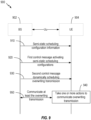
- FIG. 9 is a call flow diagram illustrating example operations 900 between a BS 902 and a UE 904 for communicating dynamically scheduled transmissions (e.g., PDSCH transmission or PUSCH transmissions) that overwrite transmissions in existing semi-statically configured scheduling occasions (e.g., SPS occasions or CG occasions).
- the BS 902 may be an example of the BS 102 in the wireless communication network 100 illustrated in FIG. 1 .
- the UE 904 may be an example of the UE 104 illustrated in FIG. 1 and may include a plurality of antenna panels that may be used for FD communication.
- a Uu interface may be established to facilitate communication between the BS 902 and UE 904, however, in other aspects, a different type of interface may be used.
- the operations 900 illustrated in FIG. 9 begin at 910 with the BS 902 transmitting, to the UE 904, semi-static scheduling configuration information.
- the semi-static scheduling configuration information may include a first semi-static scheduling configuration and a second semi-static scheduling configuration for full duplex communication.
- the first semi-static scheduling configuration comprises at least one SPS occasion in which the UE 904 is scheduled to receive a downlink transmission from the BS 902.
- the second semi-static scheduling configuration comprises at least one CG occasion in which the UE 904 is scheduled to transmit an uplink transmission to the BS 902.
- the at least one CG occasion at least partially overlaps in time with the at least one SPS occasion and, as such, full duplex communication may be used when receiving the downlink transmission in the at least one SPS occasion and transmitting the uplink transmission in the at least one CG occasion.
- the BS 902 transmits a first control message to the UE 904, activating the first semi-static scheduling configuration and the second semi-static scheduling configuration for the full duplex communication.
- the first control message may include a downlink control information (DCI) message.
- the first control message may indicate a first downlink receive beam for receiving the downlink transmission in the at least one SPS occasion and a first uplink transmit beam for transmitting the uplink transmission in the at least one CG occasion.
- the first downlink receive beam may be associated with a first antenna panel of the UE 904 and the first uplink transmit beam may be associated with a second antenna panel of the UE 904.
- the second control message may be a DCI message and comprise a dynamic grant that schedules a transmission associated with the UE that overwrites at least one of the downlink transmission in the at least one SPS occasion or the uplink transmission in the at least one CG occasion.
- the transmission that is scheduled by the second control message received at 930 in FIG. 9 comprises a PUSCH transmission.
- the PUSCH transmission overwrites the uplink transmission in the at least one CG occasion that at least partially overlaps in time with the at least one SPS occasion.
- FIG. 7 illustrates the second control message received at 930 in FIG. 9 and the transmission that is scheduled by the second control message in FIG. 9 may include the uplink (e.g., PUSCH) transmission 714 in FIG. 7 .
- the at least one SPS occasion in FIG. 9 may include the second SPS occasion 718 in FIG. 7 .
- the second control message may indicate an uplink transmit beam for transmitting the PUSCH transmission associated with the second antenna panel of the UE or another antenna panel of the UE 904.
- the uplink transmit beam for transmitting the PUSCH transmission may not be compatible with the first downlink receive beam for receiving the downlink transmission in the at least one SPS occasion (e.g., received by the UE 904 in the first control message at 920 in FIG. 9 ).
- the uplink transmit beam for transmitting the PUSCH transmission may cause too much self-interference (e.g., greater than or equal to a self-interference threshold) to the downlink receive beam used for receiving the downlink transmission in the at least one SPS occasion.
- too much self-interference e.g., greater than or equal to a self-interference threshold
- the UE 904 may take one or more actions (e.g., in block 940) to communicate the PUSCH transmission while reducing or avoiding self-interference caused to the downlink transmission in the at least one SPS occasion.
- a new field or a reserved/unused field in the second control message that schedules the PUSCH transmission may be used to indicate another downlink receive beam for the at least one SPS occasion that is overlapped with the PUSCH transmission.
- the second control message received at 930 in FIG. 9 may further indicate a second downlink receive beam for receiving the downlink transmission in the at least one SPS occasion that is compatible (e.g., self-interference below a self-interference threshold) with the uplink transmit beam for transmitting the PUSCH transmission.
- taking the one or more actions to communicate at least the overwriting transmission (e.g., transmitting the PUSCH transmission) in block 940 of FIG. 9 may include simultaneously receiving the downlink transmission in the at least one SPS occasion using the second downlink receive beam and transmitting the PUSCH transmission using the uplink transmit beam.
- the operations shown at 950 may also include simultaneously receiving the downlink transmission in the at least one SPS occasion using the second downlink receive beam.
- the second control message received at 930 in FIG. 9 further includes at least one identifier that identifies one or more specific SPS occasions of the at least one SPS occasion to use the second downlink receive beam to receive the downlink transmission.
- the UE 904 may use the second downlink receive beam to receive the downlink transmission(s) in the one or more specific SPS occasions.
- the UE 904 may use the first downlink receive beam (e.g., received in the first control message at 920) to receive other downlink transmissions in SPS occasions of the at least one SPS occasion other than the one or more specific SPS occasions identified by the at least one identifier.
- the second control message received at 930 may further include an indication specifying whether or not to drop reception of the downlink transmission in the at least one SPS occasion.
- the indication in the second control message specifies to drop the reception of the downlink transmission in the at least one SPS occasion.
- the 9 may include transmitting the PUSCH transmission as shown at 950 and not receiving the downlink transmission in the at least one SPS occasion based on the indication specifying to drop the reception of the downlink transmission in the at least one SPS occasion.
- the indication in the second control message specifying to drop the reception of the downlink transmission in the at least one SPS occasion may further indicate one or more specific SPS occasions of the at least one SPS occasion to drop the reception of the downlink transmission.
- not receiving the downlink transmission in the at least one SPS occasion comprises not receiving the downlink transmission in the one or more specific SPS occasions indicated in the second control message.
- the indication in the second control message received at 930 may specify to keep the reception of the downlink transmission in the at least one SPS occasion.
- taking the one or more actions to communicate the overwriting transmission (e.g., transmitting the PUSCH transmission) in block 940 of FIG. 9 may include transmitting the PUSCH transmission as shown at 950 and simultaneously receiving the downlink transmission in the at least one SPS occasion based on the indication specifying to keep the reception of the downlink transmission in the at least one SPS occasion.
- the UE 904 may autonomously determine whether the first downlink receive beam for receiving the downlink transmission in the at least one SPS occasion is compatible with the uplink transmit beam for transmitting the PUSCH transmission.
- the UE 904 may make this determination based on at least one of beam management measurements or a set of preconfigured candidate downlink and uplink beam pairs. For example, the UE 904 may perform beam management measurements to measure a level of self-interference caused by the uplink transmit beam for transmitting the PUSCH transmission to the first downlink receive beam for receiving the downlink transmission in the at least one SPS occasion. If the level of self-interference is greater than or equal to a self-interference threshold, the UE 904 may determine that the first downlink receive beam is not compatible with the uplink transmit beam. In other cases, when the level of self-interference is less than the self-interference threshold, the UE 904 may determine that the first downlink receive beam is compatible with the uplink transmit beam.
- taking the one or more actions to communicate at least the overwriting transmission (e.g., transmitting the PUSCH transmission) in block 940 of FIG. 9 may include simultaneously receiving the downlink transmission in the at least one SPS occasion using the second downlink receive beam and transmitting the PUSCH transmission using the uplink transmit beam.
- reducing or avoiding the self-interference caused to the downlink transmission in the at least one SPS occasion when transmitting the dynamically scheduled PUSCH transmission that overlaps the downlink transmission in the at least one SPS occasion may be based on a rule specified in a wireless communications standard.
- the rule may specify that whenever the UE 904 is dynamically scheduled with the PUSCH transmission that overlaps the downlink transmission in the at least one SPS occasion, the UE 904 should drop the reception of the downlink transmission in the at least one SPS occasion.
- taking the one or more actions to communicate the overwriting transmission e.g., transmitting the PUSCH transmission
- taking the one or more actions to communicate the overwriting transmission in block 940 of FIG. 9 may include transmitting the PUSCH transmission as shown at 950 and not receiving the downlink transmission in the at least one SPS occasion based on the rule specifying to drop the reception of the downlink transmission in the at least one SPS occasion.
- the rule may specify that whenever the UE 904 is dynamically scheduled with the PUSCH transmission that overlaps the downlink transmission in the at least one SPS occasion, the UE 904 should keep the reception of the downlink transmission in the at least one SPS occasion.
- taking the one or more actions to communicate at least the overwriting transmission (e.g., transmitting the PUSCH transmission) in block 940 of FIG. 9 may include simultaneously receiving the downlink transmission in the at least one SPS occasion using the first downlink receive beam and transmitting the PUSCH transmission using the uplink transmit beam.
- the operations shown at 950 may also include simultaneously receiving the downlink transmission in the at least one SPS occasion using the first downlink receive beam.
- the second control message received at 930 in FIG. 9 may include a bi-directional transmission configuration indicator (TCI) state for the downlink transmission in the at least one SPS occasion and the PUSCH transmission.
- the bi-directional TCI state may include spatial relationship information that indicates a set of beams for receiving downlink transmissions and transmitting uplink transmissions.
- the bi-directional TCI state may be used to indicate a pair of compatible downlink and uplink beams that may be used for receiving the downlink transmission in the at least one SPS occasion and for transmitting the PUSCH transmission.
- the bi-directional TCI state received in the second control message may indicate (via spatial relationship information) a second downlink receive beam for receiving the downlink transmission in the at least one SPS occasion and may also indicate the uplink transmit beam for transmitting the PUSCH transmission.
- taking the one or more actions to communicate at least the overwriting transmission (e.g., transmitting the PUSCH transmission) in block 940 of FIG. 9 may include simultaneously receiving the downlink transmission in the at least one SPS occasion using the second downlink receive beam indicated by the bi-directional TCI state and transmitting the PUSCH transmission using the uplink transmit beam indicated by the bi-directional TCI state.
- the operations shown at 950 may also include simultaneously receiving the downlink transmission in the at least one SPS occasion using the second downlink receive beam indicated by the bi-directional TCI state.
- the transmission that is scheduled by the second control message received at 930 in FIG. 9 comprises a PDSCH transmission.
- the PDSCH transmission overwrites the downlink transmission in the at least one SPS occasion that at least partially overlaps in time with the at least one CG occasion.
- FIG. 8 illustrates the second control message received at 930 in FIG. 9 and the transmission that is scheduled by the second control message in FIG. 9 may include the downlink (e.g., PDSCH) transmission 814 in FIG. 7 .
- the at least one CG occasion in FIG. 9 may include the second CG occasion 818 in FIG. 8 .
- the second control message may indicate a downlink receive beam for receiving the PDSCH transmission associated with the first antenna panel of the UE or another antenna panel of the UE 904.
- the downlink receive beam for receiving the PDSCH transmission may not be compatible with the first uplink transmit beam for transmitting the uplink transmission in the at least one CG occasion (e.g., received by the UE 904 in the first control message at 920 in FIG. 9 ).
- the downlink receive beam for receiving the PDSCH transmission may cause too much self-interference (e.g., greater than or equal to a self-interference threshold) to the uplink transmit beam used for transmitting the uplink transmission in the at least one CG occasion.
- too much self-interference e.g., greater than or equal to a self-interference threshold
- the UE 904 may take one or more actions (e.g., in block 940) to communicate the PDSCH transmission while reducing or avoiding self-interference caused to the uplink transmission in the at least one CG occasion.
- a new field or a reserved/unused field in the second control message that schedules the PDSCH transmission may be used to indicate another uplink transmit beam for the at least one CG occasion that is overlapped with the PDSCH transmission.
- the second control message received at 930 in FIG. 9 may further indicate a second uplink transmit beam for transmitting the uplink transmission in the at least one CG occasion that is compatible (e.g., self-interference below a self-interference threshold) with the downlink receive beam for receiving the PDSCH transmission.
- taking the one or more actions to communicate at least the overwriting transmission e.g., receiving the PDSCH transmission from the BS 902 in block 940 of FIG. 9 may include simultaneously transmitting the uplink transmission in the at least one CG occasion using the second uplink transmit beam and receiving the PDSCH transmission using the downlink receive beam indicated in the second control message.
- the operations shown at 950 may also include simultaneously transmitting the uplink transmission in the at least one CG occasion using the second uplink transmit beam.
- the second control message received at 930 in FIG. 9 further includes at least one identifier that identifies one or more specific CG occasions of the at least one CG occasion to use the second uplink transmit beam to transmit the uplink transmission.
- the UE 904 may use the second uplink transmit beam to transmit the uplink transmission(s) in the one or more specific CG occasions.
- the UE 904 may use the first uplink transmit beam (e.g., received in the first control message at 920) to transmit other uplink transmissions in CG occasions of the at least one CG occasion other than the one or more specific CG occasions identified by the at least one identifier.
- the second control message received at 930 may further include an indication specifying whether or not to drop transmission of the uplink transmission in the at least one CG occasion.
- the indication in the second control message specifies to drop the transmission of the uplink transmission in the at least one CG occasion.
- the UE 904 may autonomously determine whether the first uplink receive beam for transmitting the uplink transmission in the at least one CG occasion is compatible with the downlink receive beam for receiving the PDSCH transmission.
- the UE 904 may make this determination based on at least one of beam management measurements or a set of preconfigured candidate downlink and uplink beam pairs. For example, the UE 904 may perform beam management measurements to measure a level of self-interference caused by the downlink receive beam for receiving the PDSCH transmission to the first uplink transmit beam for transmitting the uplink transmission in the at least one CG occasion. If the level of self-interference is greater than or equal to a self-interference threshold, the UE 904 may determine that the first uplink transmit beam is not compatible with the downlink receive beam. In other cases, when the level of self-interference is less than the self-interference threshold, the UE 904 may determine that the first uplink transmit beam is compatible with the downlink receive beam.
- the UE 904 may be preconfigured with a list of candidate downlink and uplink beam pairs, indicating downlink and uplink beam pairs that are compatible with each other.
- each downlink receive beam in the list of candidate downlink and uplink beam pairs may be paired with one or more compatible uplink transmit beams and vice versa. Accordingly, when the UE 904 receives the indication of the downlink receive beam for receiving the PDSCH transmission in the second control message, the UE 904 may search the list of candidate downlink and uplink beam pairs to determine whether there is an existing beam pair including the downlink receive beam and first uplink transmit beam.
- the UE 904 may conclude that the downlink receive beam is compatible with the first uplink transmit beam. Otherwise, the UE 904 may conclude that the downlink receive beam is not compatible with the first uplink transmit beam.
- the UE 904 may select a second uplink transmit beam for transmitting the uplink transmission in the at least one CG occasion that is compatible with the downlink receive beam for receiving the PDSCH transmission.
- the UE 904 may select a second downlink receive beam for receiving the PDSCH transmission that is compatible with the first uplink receive beam for transmitting the uplink transmission in the at least one CG occasion.
- the UE 904 may select both the second uplink transmit beam for transmitting the uplink transmission in the at least one CG occasion and the second downlink receive beam for receiving the PDSCH transmission.
- the UE 904 may make the selection of the second uplink transmit beam and/or second downlink receive beam based on at least one of the beam management measurements or the set of preconfigured candidate downlink and uplink beam pairs. Further, whether the UE 904 selects the second downlink receive beam, the second uplink transmit beam, or both the second downlink receive beam and the second uplink transmit beam may be based on a rule specified in a wireless communications standard.
- taking the one or more actions to communicate at least the overwriting transmission may include simultaneously transmitting the uplink transmission in the at least one CG occasion using the second uplink transmit beam and receiving the PDSCH transmission using the downlink beam.
- taking the one or more actions to communicate at least the overwriting transmission e.g., receiving the PDSCH transmission from the BS 902 in block 940 of FIG.
- the 9 may include simultaneously transmitting the uplink transmission in the at least one CG occasion using the first uplink transmit beam (e.g., indicated in the first control message received at 910) and receiving the PDSCH transmission using the second downlink receive beam.
- taking the one or more actions to communicate at least the overwriting transmission e.g., receiving the PDSCH transmission from the BS 902 in block 940 of FIG. 9 may include simultaneously transmitting the uplink transmission in the at least one CG occasion using the second uplink transmit beam and receiving the PDSCH transmission using the second downlink receive beam.
- reducing or avoiding the self-interference caused to the uplink transmission in the at least one CG occasion when receiving the dynamically scheduled PDSCH transmission that overlaps the uplink transmission in the at least one CG occasion may be based on a rule specified in a wireless communications standard.
- the rule may specify that whenever the UE 904 is dynamically scheduled with the PDSCH transmission that overlaps the uplink transmission in the at least one CG occasion, the UE 904 should drop the transmission of the uplink transmission in the at least one CG occasion.
- taking the one or more actions to communicate the overwriting transmission e.g., receiving the PDSCH transmission from the BS 902 in block 940 of FIG. 9 may include receiving the PDSCH transmission as shown at 950 and not transmitting the uplink transmission in the at least one CG occasion based on the rule specifying to drop the transmission of the uplink transmission in the at least one CG occasion.
- the rule may specify that whenever the UE 904 is dynamically scheduled with the PDSCH transmission that overlaps the uplink transmission in the at least one CG occasion, the UE 904 should keep the reception of the uplink transmission in the at least one CG occasion.
- taking the one or more actions to communicate at least the overwriting transmission e.g., receiving the PDSCH transmission from the BS 902 in block 940 of FIG. 9 may include simultaneously transmitting the uplink transmission in the at least one CG occasion using the first uplink transmit beam (e.g., indicated in the first control message received at 910) and transmitting the PDSCH transmission using the downlink receive beam (e.g., indicated in the second control message received at 920).
- the operations shown at 950 may also include simultaneously transmitting the uplink transmission in the at least one CG occasion using the first uplink transmit beam.
- the second control message received at 930 in FIG. 9 may include a bi-directional TCI state for the uplink transmission in the at least one CG occasion and the PDSCH transmission.
- the bi-directional TCI state may include spatial relationship information that indicates a set of beams for receiving downlink transmissions and transmitting uplink transmissions.
- the bi-directional TCI state may be used to indicate a pair of compatible downlink and uplink beams that may be used for transmitting the uplink transmission in the at least one CG occasion and for receiving the PDSCH transmission.
- the bi-directional TCI state received in the second control message may indicate (via spatial relationship information) a second uplink transmit beam for transmitting the uplink transmission in the at least one CG occasion and may also indicate the downlink receive beam for receiving the PDSCH transmission.
- taking the one or more actions to communicate at least the overwriting transmission may include simultaneously transmitting the uplink transmission in the at least one CG occasion using the second uplink transmit beam indicated by the bi-directional TCI state and receiving the PDSCH transmission using the downlink receive beam indicated by the bi-directional TCI state.
- the operations shown at 950 may also include simultaneously transmitting the uplink transmission in the at least one CG occasion using the second uplink transmit beam indicated by the bi-directional TCI state.
- the second control message received at 930 in FIG. 9 may further include at least one identifier that identifies one or more specific CG occasions of the at least one CG occasion to use the bi-directional TCI state to transmit the uplink transmission in the at least one CG occasions and to receive the PDSCH transmission. Accordingly, the UE 904 may use the bi-directional TCI state to transmit the uplink transmission(s) in the one or more specific CG occasions and to simultaneously receive the PDSCH transmission.
- the BS 902 may perform complimentary techniques to those performed by the UE 904. As one example, if the UE 904 simultaneously transmits an uplink transmission and receives a downlink transmission, it should be understood that the BS 902 also simultaneously receives the uplink transmission and transmits the downlink transmission.
- FIG. 10 is a flow diagram illustrating example operations 1000 for wireless communication.
- the operations 1000 may be performed, for example, by a BS (e.g., such as the BS 102 in the wireless communication network 100 of FIG. 1 ) for communicating a dynamically scheduled transmission with a UE that overwrites a transmission in a semi-statically configured scheduling occasion for full duplex.
- the operations 1000 may be implemented as software components that are executed and run on one or more processors (e.g., controller/processor 240 of FIG. 2 ).
- the transmission and reception of signals by the BS in operations 1000 may be enabled, for example, by one or more antennas (e.g., antennas 234 of FIG. 2 ).
- the transmission and/or reception of signals by the BS may be implemented via a bus interface of one or more processors (e.g., controller/processor 240) obtaining and/or outputting signals.
- the operations 1000 begin, at 1010, with transmitting a first control message to a user equipment (UE), activating a first semi-static scheduling configuration and a second semi-static scheduling configuration for full duplex communication.
- the first semi-static scheduling configuration comprises at least one semi-persistent scheduling (SPS) occasion in which the UE is scheduled to receive a downlink transmission from the BS.
- the second semi-static scheduling configuration comprises at least one configured grant (CG) occasion in which the UE is scheduled to transmit an uplink transmission to the BS, wherein the at least one CG occasion at least partially overlaps in time with the at least one SPS occasion.
- SPS semi-persistent scheduling
- CG configured grant
- the BS transmits a second control message comprising a dynamic grant that schedules a transmission associated with the UE that overwrites at least one of the downlink transmission in the at least one SPS occasion or the uplink transmission in the at least one CG occasion.
- the BS communicates, based on the dynamic grant, at least the transmission that overwrites the at least one of the downlink transmission in the at least one SPS occasion or the uplink transmission in the at least one CG occasion with the UE.
- the transmission that is dynamically scheduled in the second control message transmitted in block 1020 comprises a physical uplink shared channel (PUSCH) transmission and overwrites the uplink transmission in the at least one CG occasion that at least partially overlaps in time with the at least one SPS occasion.
- PUSCH physical uplink shared channel
- the first control message indicates a first downlink receive beam for receiving the downlink transmission in the at least one SPS occasion. Additionally, in some cases, the second control message indicates an uplink transmit beam for transmitting the PUSCH transmission.
- the second control message includes at least one identifier that identifies one or more specific SPS occasions of the at least one SPS occasion to use the second downlink receive beam to receive the downlink transmission.
- the second control message further includes an indication specifying whether or not to drop reception of the downlink transmission in the at least one SPS occasion.
- the indication specifies to drop the reception of the downlink transmission in the at least one SPS occasion.
- communicating at least the transmission in block 1030 that overwrites the at least one of the downlink transmission in the at least one SPS occasion or the uplink transmission in the at least one CG occasion with the UE comprises: receiving the PUSCH transmission and not transmitting the downlink transmission in the at least one SPS occasion based on the indication specifying to drop the reception of the downlink transmission in the at least one SPS occasion.
- the indication specifying to drop the reception of the downlink transmission in the at least one SPS occasion further indicates one or more specific SPS occasions of the at least one SPS occasion to drop the reception of the downlink transmission.
- not transmitting the downlink transmission in the at least one SPS occasion comprises not transmitting the downlink transmission in the one or more specific SPS occasions.
- communicating at least the transmission in block 1030 that overwrites the at least one of the downlink transmission in the at least one SPS occasion or the uplink transmission in the at least one CG occasion with the UE comprises one of: simultaneously transmitting the downlink transmission in the at least one CG occasion and receiving the PUSCH transmission, or receiving the PUSCH transmission and not transmitting the downlink transmission in the at least one SPS occasion.
- the second control message includes a bi-directional transmission configuration indicator (TCI) state.
- TCI transmission configuration indicator
- the bi-directional TCI state indicates a second downlink receive beam for receiving the downlink transmission in the at least one SPS occasion and the uplink transmit beam for transmitting the PUSCH transmission.
- communicating at least the transmission in block 1030 that overwrites the at least one of the downlink transmission in the at least one SPS occasion or the uplink transmission in the at least one CG occasion with the UE comprises, based on the bi-directional TCI state, simultaneously transmitting the downlink transmission in the at least one SPS occasion and receiving the PUSCH transmission.
- the transmission that is dynamically scheduled in the second control message transmitted in block 1020 comprises a physical downlink shared channel (PDSCH) transmission and overwrites the downlink transmission in the at least one SPS occasion.
- PDSCH physical downlink shared channel
- the first control message indicates a first uplink transmit beam for transmitting the uplink transmission in the at least one CG occasion and the second control message indicates a downlink receive beam for receiving the PDSCH transmission.
- the second control message includes at least one identifier that identifies one or more specific CG occasions of the at least one CG occasion to use the second uplink transmit beam to transmit the uplink transmission.
- the second control message further includes an indication specifying whether or not to drop transmission of the uplink transmission in the at least one CG occasion.
- the indication specifies to drop the transmission of the uplink transmission in the at least one CG occasion.
- communicating at least the transmission in block 1030 that overwrites the at least one of the downlink transmission in the at least one SPS occasion or the uplink transmission in the at least one CG occasion with the UE comprises transmitting the PDSCH transmission and not receiving the uplink transmission in the at least one CG occasion based on the indication specifying to drop the transmission of the uplink transmission in the at least one CG occasion.
- the indication specifying to drop the transmission of the uplink transmission in the at least one CG occasion further indicates one or more specific CG occasions of the at least one CG occasion to drop the transmission of the uplink transmission.
- not receiving the uplink transmission in the at least one CG occasion comprises not receiving the uplink transmission in the one or more specific CG occasions.
- communicating at least the transmission in block 1030 that overwrites the at least one of the downlink transmission in the at least one SPS occasion or the uplink transmission in the at least one CG occasion with the UE comprises one of: simultaneously receiving the uplink transmission in the at least one CG occasion and transmitting the PDSCH transmission, or transmitting the PDSCH transmission and not receiving the uplink transmission in the at least one CG occasion.
- the second control message includes a bi-directional transmission configuration indicator (TCI) state.
- TCI transmission configuration indicator
- the bi-directional TCI state indicates: a second uplink transmit beam for transmitting the uplink transmission in the at least one CG occasion, and the downlink receive beam for receiving the PDSCH transmission.
- communicating at least the transmission in block 1030 that overwrites the at least one of the downlink transmission in the at least one SPS occasion or the uplink transmission in the at least one CG occasion with the UE comprises, based on the bi-directional TCI state, simultaneously receiving the uplink transmission in the at least one CG occasion and transmitting the PDSCH transmission.
- FIG. 11 is a flow diagram illustrating example operations 1100 for wireless communication, in accordance with certain aspects of the present disclosure.
- the operations 1100 may be performed, for example, by a UE (e.g., such as the UE 104 in the wireless communication network 100 of FIG. 1 ) for communicating a dynamically scheduled transmission with a BS that overwrites a transmission in a semi-statically configured scheduling occasion for full duplex.
- the operations 1100 may be complementary to the operations 1000 performed by the BS in FIG. 10 .
- the operations 1100 may be implemented as software components that are executed and run on one or more processors (e.g., controller/processor 280 of FIG. 2 ).
- the transmission and reception of signals by the UE in operations 1100 may be enabled, for example, by one or more antennas (e.g., antennas 252 of FIG. 2 ).
- the transmission and/or reception of signals by the UE may be implemented via a bus interface of one or more processors (e.g., controller/processor 280) obtaining and/or outputting signals.
- the operations 1100 begin, at 1110, with receiving a first control message from a base station (BS), activating a first semi-static scheduling configuration and a second semi-static scheduling configuration for full duplex communication.
- the first semi-static scheduling configuration comprises at least one semi-persistent scheduling (SPS) occasion in which the UE is scheduled to receive a downlink transmission from the BS.
- the second semi-static scheduling configuration comprises at least one configured grant (CG) occasion in which the UE is scheduled to transmit an uplink transmission to the BS, wherein the at least one CG occasion at least partially overlaps in time with the at least one SPS occasion.
- SPS semi-persistent scheduling
- CG configured grant
- the UE receives a second control message comprising a dynamic grant that schedules a transmission associated with the UE that overwrites at least one of the downlink transmission in the at least one SPS occasion or the uplink transmission in the at least one CG occasion.
- the UE takes one or more actions, based on the dynamic grant, to communicate, with the BS, at least the transmission that overwrites the at least one of the downlink transmission in the at least one SPS occasion or the uplink transmission in the at least one CG occasion.
- the first control message indicates a first downlink receive beam for receiving the downlink transmission in the at least one SPS occasion. Additionally, in some cases, the second control message indicates an uplink transmit beam for transmitting the PUSCH transmission.
- the second control message further indicates a second downlink receive beam for receiving the downlink transmission in the at least one SPS occasion that is compatible with the uplink transmit beam for transmitting the PUSCH transmission.
- taking the one or more actions in block 1130 to communicate, with the BS, the transmission that overwrites the at least one of the downlink transmission in the at least one SPS occasion or the uplink transmission in the at least one CG occasion comprises simultaneously receiving the downlink transmission in the at least one SPS occasion using the second downlink receive beam and transmitting the PUSCH transmission using the uplink transmit beam.
- the second control message includes at least one identifier that identifies one or more specific SPS occasions of the at least one SPS occasion to use the second downlink receive beam to receive the downlink transmission.
- the operations 1100 may also include using the first downlink receive beam to receive other downlink transmissions in SPS occasions of the at least one SPS occasion other than the one or more specific SPS occasions identified by the at least one identifier.
- the second control message further includes an indication specifying whether or not to drop reception of the downlink transmission in the at least one SPS occasion.
- the indication specifies to drop the reception of the downlink transmission in the at least one SPS occasion.
- taking the one or more actions in block 1130 to communicate, with the BS, the transmission that overwrites the at least one of the downlink transmission in the at least one SPS occasion or the uplink transmission in the at least one CG occasion comprises: transmitting the PUSCH transmission and not receiving the downlink transmission in the at least one SPS occasion based on the indication specifying to drop the reception of the downlink transmission in the at least one SPS occasion.
- the indication specifying to drop the reception of the downlink transmission in the at least one SPS occasion further indicates one or more specific SPS occasions of the at least one SPS occasion to drop the reception of the downlink transmission.
- not receiving the downlink transmission in the at least one SPS occasion comprises not receiving the downlink transmission in the one or more specific SPS occasions.
- operations 1100 further include determining whether the first downlink receive beam for receiving the downlink transmission in the at least one SPS occasion is compatible with the uplink transmit beam for transmitting the PUSCH transmission based on at least one of beam management measurements or a set of preconfigured candidate downlink and uplink beam pairs.
- taking the one or more actions in block 1130 to communicate the transmission that overwrites the at least one of the downlink transmission in the at least one SPS occasion or the uplink transmission in the at least one CG occasion comprises, when the first downlink receive beam is compatible with the uplink transmit beam, simultaneously receiving the downlink transmission in the at least one SPS occasion using the first downlink receive beam and transmitting the PUSCH transmission using the uplink transmit beam.
- taking the one or more actions in block 1130 to communicate the transmission that overwrites the at least one of the downlink transmission in the at least one SPS occasion or the uplink transmission in the at least one CG occasion comprises, when the first downlink receive beam is not compatible with the uplink transmit beam transmitting the PUSCH transmission using the uplink transmit beam and not receiving the downlink transmission in the at least one SPS occasion.
- taking the one or more actions in block 1130 to communicate the transmission that overwrites the at least one of the downlink transmission in the at least one SPS occasion or the uplink transmission in the at least one CG occasion comprises one of: simultaneously receiving the downlink transmission in the at least one SPS occasion using the first downlink receive beam and transmitting the PUSCH transmission using the uplink transmit beam, or transmitting the PUSCH transmission using the uplink transmit beam and not receiving the downlink transmission in the at least one SPS occasion.
- the second control message includes a bi-directional transmission configuration indicator (TCI) state.
- TCI transmission configuration indicator
- the bi-directional TCI state indicates a second downlink receive beam for receiving the downlink transmission in the at least one SPS occasion and the uplink transmit beam for transmitting the PUSCH transmission.
- taking the one or more actions in block 1130 to communicate the transmission that overwrites the at least one of the downlink transmission in the at least one SPS occasion or the uplink transmission in the at least one CG occasion comprises simultaneously receiving the downlink transmission in the at least one SPS occasion using the second downlink receive beam indicated by the bi-directional TCI state and transmitting the PUSCH transmission using the uplink transmit beam indicated by the bi-directional TCI state.
- operations 1100 further include, based on at least one of beam management measurements or a set of preconfigured candidate downlink and uplink beam pairs, one of: selecting a second downlink receive beam for receiving the downlink transmission in the at least one SPS occasion that is compatible with the uplink transmit beam for transmitting the PUSCH transmission or selecting a second uplink transmit beam for transmitting the PUSCH transmission that is compatible with the first downlink receive beam for receiving the downlink transmission in the at least one SPS occasion.
- taking the one or more actions in block 1130 to communicate the transmission that overwrites the at least one of the downlink transmission in the at least one SPS occasion or the uplink transmission in the at least one CG occasion comprises one of: simultaneously receiving the downlink transmission in the at least one SPS occasion using the second downlink receive beam and transmitting the PUSCH transmission using the uplink transmit beam, or simultaneously receiving the downlink transmission in the at least one SPS occasion using the first downlink receive beam and transmitting the PUSCH transmission using the second uplink transmit beam.
- the transmission that is dynamically scheduled in the second control message received in block 1120 comprises a physical downlink shared channel (PDSCH) transmission and overwrites the downlink transmission in the at least one SPS occasion.
- the first control message indicates a first uplink transmit beam for transmitting the uplink transmission in the at least one CG occasion
- the second control message indicates a downlink receive beam for receiving the PDSCH transmission.
- the second control message further indicates a second uplink transmit beam for transmitting the uplink transmission in the at least one CG occasion that is compatible with the downlink receive beam for receiving the PDSCH transmission.
- taking the one or more actions in block 1130 to communicate, with the BS, the transmission that overwrites the at least one of the downlink transmission in the at least one SPS occasion or the uplink transmission in the at least one CG occasion comprises simultaneously receiving the PDSCH transmission using the downlink receive beam and transmitting the uplink transmission in the at least one CG occasion using the second uplink transmit beam.
- the second control message includes at least one identifier that identifies one or more specific CG occasions of the at least one CG occasion to use the second uplink transmit beam to transmit the uplink transmission.
- operations 1100 may further include using the first uplink transmit beam to transmit other uplink transmissions in CG occasions of the at least one CG occasion other than the one or more specific CG occasions identified by the at least one identifier.
- the second control message further includes an indication specifying whether or not to drop transmission of the uplink transmission in the at least one CG occasion.
- the indication specifies to drop the transmission of the uplink transmission in the at least one CG occasion.
- taking the one or more actions in block 1130 to communicate, with the BS, the transmission that overwrites the at least one of the downlink transmission in the at least one SPS occasion or the uplink transmission in the at least one CG occasion comprises: receiving the PDSCH transmission and not transmitting the uplink transmission in the at least one CG occasion based on the indication specifying to drop the transmission of the uplink transmission in the at least one CG occasion.
- the indication specifying to drop the transmission of the uplink transmission in the at least one CG occasion further indicates one or more specific CG occasions of the at least one CG occasion to drop the transmission of the uplink transmission.
- not transmitting the uplink transmission in the at least one CG occasion comprises not transmitting the uplink transmission in the one or more specific CG occasions.
- operations 1100 may further include determining whether the first uplink transmit beam for transmitting the uplink transmission in the at least one CG occasion is compatible with the downlink receive beam for receiving the PDSCH transmission based on at least one of beam management measurements or a set of preconfigured candidate downlink and uplink beam pairs.
- taking the one or more actions in block 1130 to communicate the transmission that overwrites the at least one of the downlink transmission in the at least one SPS occasion or the uplink transmission in the at least one CG occasion comprises, when the first uplink transmit beam is compatible with the downlink receive beam, simultaneously transmitting the uplink transmission in the at least one CG occasion using the first uplink transmit beam and receiving the PDSCH transmission using the downlink receive beam.
- taking the one or more actions in block 1130 to communicate the transmission that overwrites the at least one of the downlink transmission in the at least one SPS occasion or the uplink transmission in the at least one CG occasion comprises, when the first uplink transmit beam is not compatible with the downlink receive beam receiving the PDSCH transmission using the downlink transmit beam, and not transmitting the uplink transmission in the at least one CG occasion.
- the second control message includes a bi-directional transmission configuration indicator (TCI) state.
- the bi-directional TCI state indicates: a second uplink transmit beam for transmitting the uplink transmission in the at least one CG occasion and the downlink receive beam for receiving the PDSCH transmission.
- taking the one or more actions in block 1130 to communicate the transmission that overwrites the at least one of the downlink transmission in the at least one SPS occasion or the uplink transmission in the at least one CG occasion comprises: simultaneously transmitting the uplink transmission in the at least one CG occasion using the second uplink transmit beam indicated by the bi-directional TCI state and receiving the PDSCH transmission using the downlink receive beam indicated by the bi-directional TCI state.
- operations 1100 may further include, based on at least one of beam management measurements or a set of preconfigured candidate downlink and uplink beam pairs, one of: selecting a second uplink transmit beam for transmitting the uplink transmission in the at least one CG occasion that is compatible with the downlink receive beam for receiving the PDSCH transmission or selecting a second downlink receive beam for receiving the PDSCH transmission that is compatible with the first uplink transmit beam for transmitting the uplink transmission in the at least one CG occasion.
- taking the one or more actions to communicate the transmission that overwrites the at least one of the downlink transmission in the at least one SPS occasion or the uplink transmission in the at least one CG occasion comprises one of: simultaneously transmitting the uplink transmission in the at least one CG occasion using the second uplink transmit beam and receiving the PDSCH transmission using the downlink receive beam or simultaneously transmitting the uplink transmission in the at least one CG occasion using the first uplink transmit beam and receiving the PDSCH transmission using the second downlink receive beam.
- FIG. 12 depicts an example communications device 1200 that includes various components operable, configured, or adapted to perform operations for the techniques disclosed herein, such as the operations depicted and described with respect to FIGs. 9-10 .
- communication device 1200 may be a base station 102 as described, for example with respect to FIGS. 1 and 2 .
- Communications device 1200 includes a processing system 1202 coupled to a transceiver 1208 (e.g., a transmitter and/or a receiver).
- Transceiver 1208 is configured to transmit (or send) and receive signals for the communications device 1200 via an antenna 1210, such as the various signals as described herein.
- Processing system 1202 may be configured to perform processing functions for communications device 1200, including processing signals received and/or to be transmitted by communications device 1200.
- Processing system 1202 includes one or more processors 1220 coupled to a computer-readable medium/memory 1230 via a bus 1206.
- computer-readable medium/memory 1230 is configured to store instructions (e.g., computer-executable code) that when executed by the one or more processors 1220, cause the one or more processors 1220 to perform the operations illustrated in FIGs. 9-10 , or other operations for performing the various techniques discussed herein for communicating a dynamically scheduled transmission with a UE that overwrites a transmission in a semi-statically configured scheduling occasion for full duplex.
- computer-readable medium/memory 1230 stores code 1231 for transmitting, code 1232 for communicating, and code 1233 for receiving.
- the one or more processors 1220 include circuitry configured to implement the code stored in the computer-readable medium/memory 1230, including circuitry 1221 for transmitting, circuitry 1222 for communicating, and circuitry 1223 for receiving.
- communications device 1200 may provide means for performing the methods described herein, including with respect to FIGs. 9-10 .
- means for transmitting or sending may include the transceivers 232 and/or antenna(s) 234 of the base station 102 illustrated in FIG. 2 and/or transceiver 1208 and antenna 1210 of the communication device 1200 in FIG. 12 .
- means for receiving may include the transceivers 232 and/or antenna(s) 234 of the base station illustrated in FIG. 2 and/or transceiver 1208 and antenna 1210 of the communication device 1200 in FIG. 12 .
- FIG. 12 is an example, and many other examples and configurations of communication device 1200 are possible.
- FIG. 13 depicts an example communications device 1300 that includes various components operable, configured, or adapted to perform operations for the techniques disclosed herein, such as the operations depicted and described with respect to FIGs. 9 and 11 .
- communication device 1300 may be a user equipment 104 as described, for example with respect to FIGS. 1 and 2 .
- Communications device 1300 includes a processing system 1302 coupled to a transceiver 1308 (e.g., a transmitter and/or a receiver).
- Transceiver 1308 is configured to transmit (or send) and receive signals for the communications device 1300 via an antenna 1310, such as the various signals as described herein.
- Processing system 1302 may be configured to perform processing functions for communications device 1300, including processing signals received and/or to be transmitted by communications device 1300.
- Processing system 1302 includes one or more processors 1320 coupled to a computer-readable medium/memory 1330 via a bus 1306.
- computer-readable medium/memory 1330 is configured to store instructions (e.g., computer-executable code) that when executed by the one or more processors 1320, cause the one or more processors 1320 to perform the operations illustrated in FIGs. 9 and 11 , or other operations for performing the various techniques discussed herein for communicating a dynamically scheduled transmission with a BS that overwrites a transmission in a semi-statically configured scheduling occasion for full duplex.
- computer-readable medium/memory 1330 stores code 1331 for receiving, code 1332 for taking one or more actions, code 1333 for transmitting, code 1334 for using, code 1335 for determining, and code 1336 for selecting.
- the one or more processors 1320 include circuitry configured to implement the code stored in the computer-readable medium/memory 1330, including circuitry 1321 for receiving, circuitry 1322 for taking one or more actions, circuitry 1323 for transmitting, circuitry 1324 for using, circuitry 1325 for determining, and circuitry 1326 for selecting.
- Various components of communications device 1300 may provide means for performing the methods described herein, including with respect to FIGs. 9 and 11 .
- means for transmitting may include the transceivers 254 and/or antenna(s) 252 of the user equipment 104 illustrated in FIG. 2 and/or transceiver 1308 and antenna 1310 of the communication device 1300 in FIG. 13 .
- means for receiving may include the transceivers 254 and/or antenna(s) 252 of the user equipment 104 illustrated in FIG. 2 and/or transceiver 1308 and antenna 1310 of the communication device 1300 in FIG. 13 .
- means for using, means for determining, and means for selecting, and means for taking one or more actions may include various processing system components, such as: the one or more processors 1320 in FIG. 13 , or aspects of the user equipment 104 depicted in FIG. 2 , including receive processor 258, transmit processor 264, TX MIMO processor 266, and/or controller/processor 280 (including FD communication component 281).
- FIG. 13 is an example, and many other examples and configurations of communication device 1300 are possible.
- WWAN wireless wide area network
- RATs radio access technologies
- aspects may be described herein using terminology commonly associated with 3G, 4G, and/or 5G (e.g., 5G new radio (NR)) wireless technologies, aspects of the present disclosure may likewise be applicable to other communication systems and standards not explicitly mentioned herein.
- 3G, 4G, and/or 5G e.g., 5G new radio (NR)
- 5G wireless communication networks may support various advanced wireless communication services, such as enhanced mobile broadband (eMBB), millimeter wave (mmWave), machine type communications (MTC), and/or mission critical targeting ultra-reliable, low-latency communications (URLLC). These services, and others, may include latency and reliability requirements.
- eMBB enhanced mobile broadband
- mmWave millimeter wave
- MTC machine type communications
- URLLC mission critical targeting ultra-reliable, low-latency communications
- various aspects of the present disclosure may be performed within the example wireless communication network 100.
- the term “cell” can refer to a coverage area of a NodeB and/or a narrowband subsystem serving this coverage area, depending on the context in which the term is used.
- the term “cell” and BS, next generation NodeB (gNB or gNodeB), access point (AP), distributed unit (DU), carrier, or transmission reception point may be used interchangeably.
- a BS may provide communication coverage for a macro cell, a pico cell, a femto cell, and/or other types of cells.
- a macro cell may generally cover a relatively large geographic area (e.g., several kilometers in radius) and may allow unrestricted access by UEs with service subscription.
- a pico cell may cover a relatively small geographic area (e.g., a sports stadium) and may allow unrestricted access by UEs with service subscription.
- a femto cell may cover a relatively small geographic area (e.g., a home) and may allow restricted access by UEs having an association with the femto cell (e.g., UEs in a Closed Subscriber Group (CSG) and UEs for users in the home).
- a BS for a macro cell may be referred to as a macro BS.
- a BS for a pico cell may be referred to as a pico BS.
- a BS for a femto cell may be referred to as a femto BS, home BS, or a home NodeB.
- Small cell 102' may operate in a licensed and/or an unlicensed frequency spectrum. When operating in an unlicensed frequency spectrum, the small cell 102' may employ NR and use the same 5 GHz unlicensed frequency spectrum as used by the Wi-Fi AP 150. Small cell 102', employing NR in an unlicensed frequency spectrum, may boost coverage to and/or increase capacity of the access network.
- Some base stations such as gNB 180 may operate in a traditional sub-6 GHz spectrum, in millimeter wave (mmWave) frequencies, and/or near mmWave frequencies in communication with the UE 104.
- mmWave millimeter wave
- the gNB 180 may be referred to as an mmWave base station.
- the communication links 120 between base stations 102 and, for example, UEs 104, may be through one or more carriers.
- base stations 102 and UEs 104 may use spectrum up to Y MHz (e.g., 5, 10, 15, 20, 100, 400, and other MHz) bandwidth per carrier allocated in a carrier aggregation of up to a total of Yx MHz (x component carriers) used for transmission in each direction.
- the carriers may or may not be adjacent to each other. Allocation of carriers may be asymmetric with respect to DL and UL (e.g., more or fewer carriers may be allocated for DL than for UL).
- the component carriers may include a primary component carrier and one or more secondary component carriers.
- a primary component carrier may be referred to as a primary cell (PCell) and a secondary component carrier may be referred to as a secondary cell (SCell).
- PCell primary cell
- SCell secondary cell
- Wireless communication network 100 further includes a Wi-Fi access point (AP) 150 in communication with Wi-Fi stations (STAs) 152 via communication links 154 in, for example, a 2.4 GHz and/or 5 GHz unlicensed frequency spectrum.
- AP Wi-Fi access point
- STAs Wi-Fi stations
- communication links 154 in, for example, a 2.4 GHz and/or 5 GHz unlicensed frequency spectrum.
- the STAs 152/AP 150 may perform a clear channel assessment (CCA) prior to communicating in order to determine whether the channel is available.
- CCA clear channel assessment
- the D2D communication link 158 may use the DL/UL WWAN spectrum.
- the D2D communication link 158 may use one or more sidelink channels, such as a physical sidelink broadcast channel (PSBCH), a physical sidelink discovery channel (PSDCH), a physical sidelink shared channel (PSSCH), and a physical sidelink control channel (PSCCH).
- PSBCH physical sidelink broadcast channel
- PSDCH physical sidelink discovery channel
- PSSCH physical sidelink shared channel
- PSCCH physical sidelink control channel
- D2D communication may be through a variety of wireless D2D communications systems, such as for example, FlashLinQ, WiMedia, Bluetooth, ZigBee, Wi-Fi based on the IEEE 802.11 standard, 4G (e.g., LTE), or 5G (e.g., NR), to name a few options.
- wireless D2D communications systems such as for example, FlashLinQ, WiMedia, Bluetooth, ZigBee, Wi-Fi based on the IEEE 802.11 standard, 4G (e.g., LTE), or 5G (e.g., NR), to name a few options.
- IP Internet protocol
- Serving Gateway 166 which itself is connected to PDN Gateway 172.
- PDN Gateway 172 provides UE IP address allocation as well as other functions.
- PDN Gateway 172 and the BM-SC 170 are connected to the IP Services 176, which may include, for example, the Internet, an intranet, an IP Multimedia Subsystem (IMS), a PS Streaming Service, and/or other IP services.
- IMS IP Multimedia Subsystem
- BM-SC 170 may provide functions for MBMS user service provisioning and delivery.
- BM-SC 170 may serve as an entry point for content provider MBMS transmission, may be used to authorize and initiate MBMS Bearer Services within a public land mobile network (PLMN), and may be used to schedule MBMS transmissions.
- PLMN public land mobile network
- MBMS Gateway 168 may be used to distribute MBMS traffic to the base stations 102 belonging to a Multicast Broadcast Single Frequency Network (MBSFN) area broadcasting a particular service, and may be responsible for session management (start/stop) and for collecting eMBMS related charging information.
- MMSFN Multicast Broadcast Single Frequency Network
- 5GC 190 may include an Access and Mobility Management Function (AMF) 192, other AMFs 193, a Session Management Function (SMF) 194, and a User Plane Function (UPF) 195.
- AMF 192 may be in communication with a Unified Data Management (UDM) 196.
- UDM Unified Data Management
- AMF 192 is generally the control node that processes the signaling between UEs 104 and 5GC 190. Generally, AMF 192 provides QoS flow and session management.
- IP Services 197 may include, for example, the Internet, an intranet, an IP Multimedia Subsystem (IMS), a PS Streaming Service, and/or other IP services.
- IMS IP Multimedia Subsystem
- BS 102 and UE 104 e.g., the wireless communication network 100 of FIG. 1
- UE 104 may be used to implement aspects of the present disclosure.
- a transmit processor 220 may receive data from a data source 212 and control information from a controller/processor 240.
- the control information may be for the physical broadcast channel (PBCH), physical control format indicator channel (PCFICH), physical hybrid ARQ indicator channel (PHICH), physical downlink control channel (PDCCH), group common PDCCH (GC PDCCH), and others.
- the data may be for the physical downlink shared channel (PDSCH), in some examples.
- a medium access control (MAC)-control element is a MAC layer communication structure that may be used for control command exchange between wireless nodes.
- the MAC-CE may be carried in a shared channel such as a physical downlink shared channel (PDSCH), a physical uplink shared channel (PUSCH), or a physical sidelink shared channel (PSSCH).
- PDSCH physical downlink shared channel
- PUSCH physical uplink shared channel
- PSSCH physical sidelink shared channel
- Processor 220 may process (e.g., encode and symbol map) the data and control information to obtain data symbols and control symbols, respectively. Transmit processor 220 may also generate reference symbols, such as for the primary synchronization signal (PSS), secondary synchronization signal (SSS), PBCH demodulation reference signal (DMRS), and channel state information reference signal (CSI-RS).
- PSS primary synchronization signal
- SSS secondary synchronization signal
- DMRS PBCH demodulation reference signal
- CSI-RS channel state information reference signal
- Transmit (TX) multiple-input multiple-output (MIMO) processor 230 may perform spatial processing (e.g., precoding) on the data symbols, the control symbols, and/or the reference symbols, if applicable, and may provide output symbol streams to the modulators (MODs) in transceivers 232a-232t.
- Each modulator in transceivers 232a-232t may process a respective output symbol stream (e.g., for OFDM) to obtain an output sample stream.
- Each modulator may further process (e.g., convert to analog, amplify, filter, and upconvert) the output sample stream to obtain a downlink signal.
- Downlink signals from the modulators in transceivers 232a-232t may be transmitted via the antennas 234a-234t, respectively.
- antennas 252a-252r may receive the downlink signals from the BS 102 and may provide received signals to the demodulators (DEMODs) in transceivers 254a-254r, respectively.
- Each demodulator in transceivers 254a-254r may condition (e.g., filter, amplify, downconvert, and digitize) a respective received signal to obtain input samples.
- Each demodulator may further process the input samples (e.g., for OFDM) to obtain received symbols.
- MIMO detector 256 may obtain received symbols from all the demodulators in transceivers 254a-254r, perform MIMO detection on the received symbols if applicable, and provide detected symbols.
- Receive processor 258 may process (e.g., demodulate, deinterleave, and decode) the detected symbols, provide decoded data for the UE 104 to a data sink 260, and provide decoded control information to a controller/processor 280.
- transmit processor 264 may receive and process data (e.g., for the physical uplink shared channel (PUSCH)) from a data source 262 and control information (e.g., for the physical uplink control channel (PUCCH) from the controller/processor 280. Transmit processor 264 may also generate reference symbols for a reference signal (e.g., for the sounding reference signal (SRS)). The symbols from the transmit processor 264 may be precoded by a TX MIMO processor 266 if applicable, further processed by the modulators in transceivers 254a-254r (e.g., for SC-FDM), and transmitted to BS 102.
- data e.g., for the physical uplink shared channel (PUSCH)
- control information e.g., for the physical uplink control channel (PUCCH) from the controller/processor 280.
- Transmit processor 264 may also generate reference symbols for a reference signal (e.g., for the sounding reference signal (SRS)).
- the uplink signals from UE 104 may be received by antennas 234at, processed by the demodulators in transceivers 232a-232t, detected by a MIMO detector 236 if applicable, and further processed by a receive processor 238 to obtain decoded data and control information sent by UE 104.
- Receive processor 238 may provide the decoded data to a data sink 239 and the decoded control information to the controller/processor 240.
- Memories 242 and 282 may store data and program codes for BS 102 and UE 104, respectively.
- Scheduler 244 may schedule UEs for data transmission on the downlink and/or uplink.
- 5G may utilize orthogonal frequency division multiplexing (OFDM) with a cyclic prefix (CP) on the uplink and downlink. 5G may also support half-duplex operation using time division duplexing (TDD). OFDM and single-carrier frequency division multiplexing (SC-FDM) partition the system bandwidth into multiple orthogonal subcarriers, which are also commonly referred to as tones and bins. Each subcarrier may be modulated with data. Modulation symbols may be sent in the frequency domain with OFDM and in the time domain with SC-FDM. The spacing between adjacent subcarriers may be fixed, and the total number of subcarriers may be dependent on the system bandwidth. The minimum resource allocation, called a resource block (RB), may be 12 consecutive subcarriers in some examples.
- RB resource block
- the system bandwidth may also be partitioned into subbands.
- a subband may cover multiple RBs.
- NR may support a base subcarrier spacing (SCS) of 15 KHz and other SCS may be defined with respect to the base SCS (e.g., 30 kHz, 60 kHz, 120 kHz, 240 kHz, and others).
- SCS base subcarrier spacing
- FIGS. 3A-3D depict various example aspects of data structures for a wireless communication network, such as wireless communication network 100 of FIG. 1 .
- the 5G frame structure may be frequency division duplex (FDD), in which for a particular set of subcarriers (carrier system bandwidth), subframes within the set of subcarriers are dedicated for either DL or UL.
- 5G frame structures may also be time division duplex (TDD), in which for a particular set of subcarriers (carrier system bandwidth), subframes within the set of subcarriers are dedicated for both DL and UL.
- FDD frequency division duplex
- TDD time division duplex
- the 5G frame structure is assumed to be TDD, with subframe 4 being configured with slot format 28 (with mostly DL), where D is DL, U is UL, and X is flexible for use between DL/UL, and subframe 3 being configured with slot format 34 (with mostly UL). While subframes 3, 4 are shown with slot formats 34, 28, respectively, any particular subframe may be configured with any of the various available slot formats 0-61. Slot formats 0, 1 are all DL, UL, respectively. Other slot formats 2-61 include a mix of DL, UL, and flexible symbols.
- UEs are configured with the slot format (dynamically through DL control information (DCI), or semi-statically/statically through radio resource control (RRC) signaling) through a received slot format indicator (SFI).
- DCI DL control information
- RRC radio resource control
- SFI received slot format indicator
- a frame (10 ms) may be divided into 10 equally sized subframes (1 ms). Each subframe may include one or more time slots. Subframes may also include mini-slots, which may include 7, 4, or 2 symbols. In some examples, each slot may include 7 or 14 symbols, depending on the slot configuration.
- each slot may include 14 symbols, and for slot configuration 1, each slot may include 7 symbols.
- the symbols on DL may be cyclic prefix (CP) OFDM (CP-OFDM) symbols.
- the symbols on UL may be CP-OFDM symbols (for high throughput scenarios) or discrete Fourier transform (DFT) spread OFDM (DFT-s-OFDM) symbols (also referred to as single carrier frequency-division multiple access (SC-FDMA) symbols) (for power limited scenarios; limited to a single stream transmission).
- CP cyclic prefix
- DFT-s-OFDM discrete Fourier transform
- SC-FDMA single carrier frequency-division multiple access
- the number of slots within a subframe is based on the slot configuration and the numerology.
- different numerologies ( ⁇ ) 0 to 5 allow for 1, 2, 4, 8, 16, and 32 slots, respectively, per subframe.
- different numerologies 0 to 2 allow for 2, 4, and 8 slots, respectively, per subframe.
- the subcarrier spacing and symbol length/duration are a function of the numerology.
- the subcarrier spacing may be equal to 2 ⁇ ⁇ 15 kHz, where ⁇ is the numerology 0 to 5.
- the symbol length/duration is inversely related to the subcarrier spacing.
- the slot duration is 0.25 ms
- the subcarrier spacing is 60 kHz
- the symbol duration is approximately 16.67 ⁇ s.
- a resource grid may be used to represent the frame structure.
- Each time slot includes a resource block (RB) (also referred to as physical RBs (PRBs)) that extends 12 consecutive subcarriers.
- RB resource block
- PRBs physical RBs
- the resource grid is divided into multiple resource elements (REs). The number of bits carried by each RE depends on the modulation scheme.
- the RS may include demodulation RS (DM-RS) (indicated as Rx for one particular configuration, where 100x is the port number, but other DM-RS configurations are possible) and channel state information reference signals (CSI-RS) for channel estimation at the UE.
- DM-RS demodulation RS
- CSI-RS channel state information reference signals
- the RS may also include beam measurement RS (BRS), beam refinement RS (BRRS), and phase tracking RS (PT-RS).
- BRS beam measurement RS
- BRRS beam refinement RS
- PT-RS phase tracking RS
- FIG. 3B illustrates an example of various DL channels within a subframe of a frame.
- the physical downlink control channel (PDCCH) carries DCI within one or more control channel elements (CCEs), each CCE including nine RE groups (REGs), each REG including four consecutive REs in an OFDM symbol.
- CCEs control channel elements
- REGs RE groups
- a primary synchronization signal may be within symbol 2 of particular subframes of a frame.
- the PSS is used by a UE (e.g., 104 of FIGS. 1 and 2 ) to determine subframe/symbol timing and a physical layer identity.
- a secondary synchronization signal may be within symbol 4 of particular subframes of a frame.
- the SSS is used by a UE to determine a physical layer cell identity group number and radio frame timing.
- the UE can determine a physical cell identifier (PCI). Based on the PCI, the UE can determine the locations of the aforementioned DM-RS.
- the physical broadcast channel (PBCH) which carries a master information block (MIB), may be logically grouped with the PSS and SSS to form a synchronization signal (SS)/PBCH block.
- the MIB provides a number of RBs in the system bandwidth and a system frame number (SFN).
- the physical downlink shared channel (PDSCH) carries user data, broadcast system information not transmitted through the PBCH such as system information blocks (SIBs), and paging messages.
- SIBs system information blocks
- some of the REs carry DM-RS (indicated as R for one particular configuration, but other DM-RS configurations are possible) for channel estimation at the base station.
- the UE may transmit DM-RS for the physical uplink control channel (PUCCH) and DM-RS for the physical uplink shared channel (PUSCH).
- the PUSCH DM-RS may be transmitted in the first one or two symbols of the PUSCH.
- the PUCCH DM-RS may be transmitted in different configurations depending on whether short or long PUCCHs are transmitted and depending on the particular PUCCH format used.
- the UE may transmit sounding reference signals (SRS).
- the SRS may be transmitted in the last symbol of a subframe.
- the SRS may have a comb structure, and a UE may transmit SRS on one of the combs.
- the SRS may be used by a base station for channel quality estimation to enable frequency-dependent scheduling on the UL.
- FIG. 3D illustrates an example of various UL channels within a subframe of a frame.
- the PUCCH may be located as indicated in one configuration.
- the PUCCH carries uplink control information (UCI), such as scheduling requests, a channel quality indicator (CQI), a precoding matrix indicator (PMI), a rank indicator (RI), and HARQ ACK/NACK feedback.
- UCI uplink control information
- the PUSCH carries data, and may additionally be used to carry a buffer status report (BSR), a power headroom report (PHR), and/or UCI.
- BSR buffer status report
- PHR power headroom report
- the preceding description provides examples of communicating a dynamically scheduled transmission with a UE that overwrites a transmission in a semi-statically configured scheduling occasion for full duplex in communication systems.
- the preceding description is provided to enable any person skilled in the art to practice the various aspects described herein.
- the examples discussed herein are not limiting of the scope, applicability, or aspects set forth in the claims.
- Various modifications to these aspects will be readily apparent to those skilled in the art, and the generic principles defined herein may be applied to other aspects. For example, changes may be made in the function and arrangement of elements discussed without departing from the scope of the disclosure.
- Various examples may omit, substitute, or add various procedures or components as appropriate.
- the techniques described herein may be used for various wireless communication technologies, such as 5G (e.g., 5G NR), 3GPP Long Term Evolution (LTE), LTE-Advanced (LTE-A), code division multiple access (CDMA), time division multiple access (TDMA), frequency division multiple access (FDMA), orthogonal frequency division multiple access (OFDMA), single-carrier frequency division multiple access (SC-FDMA), time division synchronous code division multiple access (TD-SCDMA), and other networks.
- LTE Long Term Evolution
- LTE-A LTE-Advanced
- CDMA code division multiple access
- TDMA time division multiple access
- FDMA frequency division multiple access
- OFDMA orthogonal frequency division multiple access
- SC-FDMA single-carrier frequency division multiple access
- TD-SCDMA time division synchronous code division multiple access
- a CDMA network may implement a radio technology such as Universal Terrestrial Radio Access (UTRA), cdma2000, and others.
- UTRA includes Wideband CDMA (WC
- cdma2000 covers IS-2000, IS-95 and IS-856 standards.
- a TDMA network may implement a radio technology such as Global System for Mobile Communications (GSM).
- GSM Global System for Mobile Communications
- An OFDMA network may implement a radio technology such as NR (e.g. 5G RA), Evolved UTRA (E-UTRA), Ultra Mobile Broadband (UMB), IEEE 802.11 (Wi-Fi), IEEE 802.16 (WiMAX), IEEE 802.20, Flash-OFDMA, and others.
- E-UTRA Evolved UTRA
- UMB Ultra Mobile Broadband
- Wi-Fi Wi-Fi
- WiMAX IEEE 802.16
- Flash-OFDMA Flash-OFDMA
- UTRA and E-UTRA are part of Universal Mobile Telecommunication System (UMTS).
- LTE and LTE-A are releases of UMTS that use E-UTRA.
- UTRA, E-UTRA, UMTS, LTE, LTE-A and GSM are described in documents from an organization named "3rd Generation Partnership Project” (3GPP).
- cdma2000 and UMB are described in documents from an organization named “3rd Generation Partnership Project 2" (3GPP2).
- NR is an emerging wireless communications technology under development.
- a general purpose processor may be a microprocessor, but in the alternative, the processor may be any commercially available processor, controller, microcontroller, or state machine.
- a processor may also be implemented as a combination of computing devices, e.g., a combination of a DSP and a microprocessor, a plurality of microprocessors, one or more microprocessors in conjunction with a DSP core, a system on a chip (SoC), or any other such configuration.
- SoC system on a chip
- an example hardware configuration may comprise a processing system in a wireless node.
- the processing system may be implemented with a bus architecture.
- the bus may include any number of interconnecting buses and bridges depending on the specific application of the processing system and the overall design constraints.
- the bus may link together various circuits including a processor, machine-readable media, and a bus interface.
- the bus interface may be used to connect a network adapter, among other things, to the processing system via the bus.
- the network adapter may be used to implement the signal processing functions of the PHY layer.
- a user interface e.g., keypad, display, mouse, joystick, touchscreen, biometric sensor, proximity sensor, light emitting element, and others
- a user interface e.g., keypad, display, mouse, joystick, touchscreen, biometric sensor, proximity sensor, light emitting element, and others
- the bus may also link various other circuits such as timing sources, peripherals, voltage regulators, power management circuits, and the like, which are well known in the art, and therefore, will not be described any further.
- the processor may be implemented with one or more general-purpose and/or special-purpose processors. Examples include microprocessors, microcontrollers, DSP processors, and other circuitry that can execute software. Those skilled in the art will recognize how best to implement the described functionality for the processing system depending on the particular application and the overall design constraints imposed on the overall system.
- the functions may be stored or transmitted over as one or more instructions or code on a computer readable medium.
- Software shall be construed broadly to mean instructions, data, or any combination thereof, whether referred to as software, firmware, middleware, microcode, hardware description language, or otherwise.
- Computer-readable media include both computer storage media and communication media including any medium that facilitates transfer of a computer program from one place to another.
- the processor may be responsible for managing the bus and general processing, including the execution of software modules stored on the machine-readable storage media.
- a computer-readable storage medium may be coupled to a processor such that the processor can read information from, and write information to, the storage medium. In the alternative, the storage medium may be integral to the processor.
- the machine-readable media may include a transmission line, a carrier wave modulated by data, and/or a computer readable storage medium with instructions stored thereon separate from the wireless node, all of which may be accessed by the processor through the bus interface.
- the machine-readable media, or any portion thereof may be integrated into the processor, such as the case may be with cache and/or general register files.
- machine-readable storage media may include, by way of example, RAM (Random Access Memory), flash memory, ROM (Read Only Memory), PROM (Programmable Read-Only Memory), EPROM (Erasable Programmable Read-Only Memory), EEPROM (Electrically Erasable Programmable Read-Only Memory), registers, magnetic disks, optical disks, hard drives, or any other suitable storage medium, or any combination thereof.
- RAM Random Access Memory
- ROM Read Only Memory
- PROM PROM
- EPROM Erasable Programmable Read-Only Memory
- EEPROM Electrical Erasable Programmable Read-Only Memory
- registers magnetic disks, optical disks, hard drives, or any other suitable storage medium, or any combination thereof.
- the machine-readable media may be embodied in a computer-program product.
- a software module may comprise a single instruction, or many instructions, and may be distributed over several different code segments, among different programs, and across multiple storage media.
- the computer-readable media may comprise a number of software modules.
- the software modules include instructions that, when executed by an apparatus such as a processor, cause the processing system to perform various functions.
- the software modules may include a transmission module and a receiving module. Each software module may reside in a single storage device or be distributed across multiple storage devices.
- a software module may be loaded into RAM from a hard drive when a triggering event occurs.
- the processor may load some of the instructions into cache to increase access speed.
- One or more cache lines may then be loaded into a general register file for execution by the processor.
- determining encompasses a wide variety of actions. For example, “determining” may include calculating, computing, processing, deriving, investigating, looking up (e.g., looking up in a table, a database or another data structure), ascertaining and the like. Also, “determining” may include receiving (e.g., receiving information), accessing (e.g., accessing data in a memory) and the like. Also, “determining” may include resolving, selecting, choosing, establishing and the like.
Landscapes
- Engineering & Computer Science (AREA)
- Computer Networks & Wireless Communication (AREA)
- Signal Processing (AREA)
- Mobile Radio Communication Systems (AREA)
Claims (15)
- Ein Verfahren (1100) für eine drahtlose Kommunikation durch ein Benutzergerät (User Equipment bzw. UE) aufweisend:Empfangen (1110) einer ersten Steuernachricht von einer Basisstation (BS), die eine erste semistatische Planungskonfiguration und eine zweite semistatische Planungskonfiguration für eine Vollduplex-Kommunikation aktiviert, wobei:die erste semistatische Planungskonfiguration wenigstens eine Semipersistente-Planung (Semi-Persistent Scheduling bzw. SPS)-Gelegenheit, in welcher das UE für das Empfangen einer Abwärtsstrecke-Sendung von der BS geplant ist, aufweist, unddie zweite semistatische Planungskonfiguration wenigstens eine Konfigurierte-Gewährung (Configured Grant bzw. CG)-Gelegenheit, in welcher das UE für das Senden einer Aufwärtsstrecke-Sendung an die BS geplant ist, aufweist, wobei die wenigstens eine CG-Gelegenheit wenigstens teilweise in der Zeit mit der wenigstens einen SPS-Gelegenheit überlappt,Empfangen (1120) einer zweiten Steuernachricht, die eine dynamische Gewährung aufweist, die eine mit dem UE assoziierte Sendung plant, die die Abwärtsstrecke-Sendung in der wenigstens einen SPS-Gelegenheit und/oder die Aufwärtsstrecke-Sendung in der wenigstens einen CG-Gelegenheit überschreibt, undErgreifen (1130) einer oder mehrerer Aktionen, basierend auf der dynamischen Gewährung, für das Kommunizieren, mit der BS, der wenigstens einen Sendung, die die Abwärtsstrecke-Sendung in der wenigstens einen SPS-Gelegenheit und/oder die Aufwärtsstrecke-Sendung in der wenigstens einen CG-Gelegenheit überschreibt.
- Verfahren nach Anspruch 1, wobei die Sendung eine Gemeinsamer-Physikalischer-Aufwärtsstreckekanal (PUSCH)-Sendung ist und die Aufwärtsstrecke-Sendung in der wenigstens einen CG-Gelegenheit, die wenigstens teilweise in der Zeit mit der wenigstens einen SPS-Gelegenheit überlappt, überschreibt.
- Verfahren nach Anspruch 2, wobei:die erste Steuernachricht einen ersten Abwärtsstrecke-Empfangsstrahl für das Empfangen der Abwärtsstrecke-Sendung in der wenigstens einen SPS-Gelegenheit angibt, unddie zweite Steuernachricht einen Aufwärtsstrecke-Sendestrahl für das Senden der PUSCH-Sendung angibt.
- Verfahren nach Anspruch 3, wobei:die zweite Steuernachricht weiterhin einen zweiten Abwärtsstrecke-Empfangsstrahl für das Empfangen der Abwärtsstrecke-Sendung in der wenigstens einen SPS-Gelegenheit, der mit dem Aufwärtsstrecke-Sendestrahl für das Senden der PUSCH-Sendung kompatibel ist, angibt, unddas Ergreifen der einen oder der mehreren Aktionen für das Kommunizieren, mit der BS, der Sendung, die die Abwärtsstrecke-Sendung in der wenigstens einen SPS-Gelegenheit und/oder die Aufwärtsstrecke-Sendung in der wenigstens einen CG-Gelegenheit überschreibt, aufweist:
gleichzeitiges Empfangen der Abwärtsstrecke-Sendung in der wenigstens einen SPS-Gelegenheit unter Verwendung des zweiten Abwärtsstrecke-Empfangsstrahls, und Senden der PUSCH-Sendung unter Verwendung des Aufwärtsstrecke-Sendestrahls. - Verfahren nach Anspruch 3, wobei die zweite Steuernachricht weiterhin eine Angabe enthält, die spezifiziert, ob der Empfang der Abwärtsstrecke-Sendung in der wenigstens einen SPS-Gelegenheit aufgegeben werden soll oder nicht.
- Verfahren nach Anspruch 3, das weiterhin das Bestimmen, ob der erste Abwärtsstrecke-Empfangsstrahl für das Empfangen der Abwärtsstrecke-Sendung in der wenigstens einen SPS-Gelegenheit mit dem Aufwärtsstrecke-Sendestrahl für das Senden der PUSCH-Sendung kompatibel ist, basierend auf Strahlverwaltungsmessungen und/oder einem Satz von vorkonfigurierten Kandidaten-Abwärtsstrecke/Aufwärtsstrecke-Strahlpaaren aufweist.
- Verfahren nach Anspruch 3, wobei, basierend auf einer in einem Drahtloskommunikationsstandard spezifizierten Regel, das Ergreifen der einen oder der mehreren Aktionen für das Kommunizieren der Sendung, die die Abwärtsstrecke-Sendung in der wenigstens einen SPS-Gelegenheit und/oder die Aufwärtsstrecke-Sendung in der wenigstens einen CG-Gelegenheit überschreibt, eines der Folgenden aufweist:gleichzeitiges Empfangen der Abwärtsstrecke-Sendung in der wenigstens einen SPS-Gelegenheit unter Verwendung des ersten Abwärtsstrecke-Empfangsstrahls, und Senden der PUSCH-Sendung unter Verwendung des Aufwärtsstrecke-Sendestrahls, oderSenden der PUSCH-Sendung unter Verwendung des Aufwärtsstrecke-Sendestrahls, und nicht-Empfangen der Abwärtsstrecke-Sendung in der wenigstens einen SPS-Gelegenheit.
- Verfahren nach Anspruch 3, wobei:die zweite Steuernachricht einen Bidirektionaler-Sendungskonfiguration-Indikator (Transmission Configuration Indicator bzw. TCI)-Zustand enthält, undder bidirektionale TCI-Zustand angibt:einen zweiten Abwärtsstrecke-Empfangsstrahl für das Empfangen der Abwärtsstrecke-Sendung in der wenigstens einen SPS-Gelegenheit, undden Aufwärtsstrecke-Sendestrahl für das Senden der PUSCH-Sendung.
- Verfahren nach Anspruch 3, das weiterhin, basierend auf Strahlverwaltungsmessungen und/oder einem Satz von vorkonfigurierten Kandidaten-Abwärtsstrecke/Aufwärtsstrecke-Strahlpaaren, eines der Folgenden aufweist:Auswählen eines zweiten Abwärtsstrecke-Empfangsstrahls für das Empfangen der Abwärtsstrecke-Sendung in der wenigstens einen SPS-Gelegenheit, der mit dem Aufwärtsstrecke-Sendestrahl für das Senden der PUSCH-Sendung kompatibel ist, oderAuswählen eines zweiten Aufwärtsstrecke-Sendestrahls für das Senden der PUSCH-Sendung, der mit dem ersten Abwärtsstrecke-Empfangsstrahl für das empfangen der Abwärtsstrecke-Sendung in der wenigstens einen SPS-Gelegenheit kompatibel ist.
- Verfahren nach Anspruch 1, wobei die Sendung eine Gemeinsamer-Physikalischer-Abwärtsstreckekanal (PDSCH)-Sendung ist und die Abwärtsstrecke-Sendung in der wenigstens einen SPS-Gelegenheit überschreibt.
- Verfahren nach Anspruch 10, wobei:die erste Steuernachricht einen ersten Aufwärtsstrecke-Sendestrahl für das Senden der Aufwärtsstrecke-Sendung in der wenigstens einen CG-Gelegenheit angibt, unddie zweite Steuernachricht einen Abwärtsstrecke-Empfangsstrahl für das Empfangen der PDSCH-Sendung angibt.
- Verfahren nach Anspruch 11, wobei:die zweite Steuernachricht weiterhin einen zweiten Aufwärtsstrecke-Sendestrahl für das Senden der Aufwärtsstrecke-Sendung in der wenigstens einen CG-Gelegenheit, der mit dem Abwärtsstrecke-Empfangsstrahl für das Empfangen der PDSCH-Sendung kompatibel ist, angibt, unddas Ergreifen der einen oder der mehreren Aktionen für das Kommunizieren, mit der BS, der Sendung, die die Abwärtsstrecke-Sendung in der wenigstens einen SPS-Gelegenheit und/oder die Aufwärtsstrecke-Sendung in der wenigstens einen CG-Gelegenheit überschreibt, aufweist:
gleichzeitiges Empfangen der PDSCH-Sendung unter Verwendung des Abwärtsstrecke-Empfangsstrahls, und Senden der Aufwärtsstrecke-Gelegenheit in der wenigstens einen CG-Gelegenheit unter Verwendung des zweiten Aufwärtsstrecke-Sendestrahls. - Verfahren nach Anspruch 11, wobei die zweite Steuernachricht weiterhin eine Angabe, die spezifiziert, ob das Senden der Aufwärtsstrecke-Sendung in der wenigstens einen CG-Gelegenheit aufgegeben werden soll oder nicht, enthält.
- Verfahren nach Anspruch 11, das weiterhin das Bestimmen, ob der erste Aufwärtsstrecke-Sendestrahl für das Senden der Aufwärtsstrecke-Sendung in der wenigstens einen CG-Gelegenheit mit dem Abwärtsstrecke-Empfangsstrahl für das Empfangen der PDSCH-Gelegenheit kompatibel ist, basierend auf Strahlverwaltungsmessungen und/oder einem Satz von vorkonfigurierten Kandidaten-Abwärtsstrecke/Aufwärtsstrecke-Strahlpaaren aufweist.
- Eine Vorrichtung (1300) für eine drahtlose Kommunikation, aufweisend:Mittel (1321, 1331) zum Empfangen einer ersten Steuernachricht von einer Basisstation (BS), die eine erste semistatische Planungskonfiguration und eine zweite semistatische Planungskonfiguration für eine Vollduplex-Kommunikation aktiviert, wobei:die erste semistatische Planungskonfiguration wenigstens eine Semipersistente-Planung (Semi-Persistent Scheduling bzw. SPS)-Gelegenheit, in welcher das UE für das Empfangen einer Abwärtsstrecke-Sendung von der BS geplant ist, aufweist, unddie zweite semistatische Planungskonfiguration wenigstens eine Konfigurierte-Gewährung (Configured Grant bzw. CG)-Gelegenheit, in welcher das UE für das Senden einer Aufwärtsstrecke-Sendung an die BS geplant ist, aufweist, wobei die wenigstens eine CG-Gelegenheit wenigstens teilweise in der Zeit mit der wenigstens einen SPS-Gelegenheit überlappt,Mittel (1321, 1331) zum Empfangen einer zweiten Steuernachricht, die eine dynamische Gewährung aufweist, die eine mit dem UE assoziierte Sendung plant, die die Abwärtsstrecke-Sendung in der wenigstens einen SPS-Gelegenheit und/oder die Aufwärtsstrecke-Sendung in der wenigstens einen CG-Gelegenheit überschreibt, undMittel (1322, 1332) zum Ergreifen einer oder mehrerer Aktionen, basierend auf der dynamischen Gewährung, für das Kommunizieren, mit der BS, der wenigstens einen Sendung, die die Abwärtsstrecke-Sendung in der wenigstens einen SPS-Gelegenheit und/oder die Aufwärtsstrecke-Sendung in der wenigstens einen CG-Gelegenheit überschreibt.
Applications Claiming Priority (2)
| Application Number | Priority Date | Filing Date | Title |
|---|---|---|---|
| US17/393,272 US12010698B2 (en) | 2021-08-03 | 2021-08-03 | Techniques for managing semi-static scheduling occasion overwrites for full duplex communication |
| PCT/US2022/072690 WO2023015058A1 (en) | 2021-08-03 | 2022-06-01 | Techniques for managing semi-static scheduling occasion overwrites for full duplex communication |
Publications (2)
| Publication Number | Publication Date |
|---|---|
| EP4381872A1 EP4381872A1 (de) | 2024-06-12 |
| EP4381872B1 true EP4381872B1 (de) | 2025-05-07 |
Family
ID=82482797
Family Applications (1)
| Application Number | Title | Priority Date | Filing Date |
|---|---|---|---|
| EP22740720.2A Active EP4381872B1 (de) | 2021-08-03 | 2022-06-01 | Verfahren zur verwaltung von überschreibungen der halbstatischen planungsgelegenheiten für vollduplexkommunikation |
Country Status (4)
| Country | Link |
|---|---|
| US (1) | US12010698B2 (de) |
| EP (1) | EP4381872B1 (de) |
| CN (1) | CN117716782A (de) |
| WO (1) | WO2023015058A1 (de) |
Families Citing this family (6)
| Publication number | Priority date | Publication date | Assignee | Title |
|---|---|---|---|---|
| US20230254850A1 (en) * | 2022-01-14 | 2023-08-10 | Electronics And Telecommunications Research Institute | Method and apparatus for scheduling data channel |
| KR102906786B1 (ko) * | 2022-04-07 | 2026-01-05 | 엘지전자 주식회사 | 무선 통신 시스템에서 주기적인 상향링크 자원과 주기적인 하향링크 자원의 쌍을 관리하는 방법 및 장치 |
| CN117676815A (zh) * | 2022-08-10 | 2024-03-08 | 联发科技(新加坡)私人有限公司 | 接收波束的处理方法及其通信装置 |
| CN118509137A (zh) * | 2023-02-15 | 2024-08-16 | 华为技术有限公司 | 上行链路控制信息的发送方法及装置 |
| US12452869B2 (en) * | 2023-03-16 | 2025-10-21 | Qualcomm Incorporated | Indication of unused uplink shared channel occasions |
| US20250227690A1 (en) * | 2024-01-10 | 2025-07-10 | Qualcomm Incorporated | Full-duplex considerations for configured grant transmission occasions |
Family Cites Families (11)
| Publication number | Priority date | Publication date | Assignee | Title |
|---|---|---|---|---|
| US9647823B2 (en) * | 2015-05-19 | 2017-05-09 | Qualcomm Incorporated | Enhanced scheduling procedure for full duplex access point |
| US10342038B2 (en) | 2016-10-04 | 2019-07-02 | Qualcomm Incorporated | Method and apparatus for scheduling multiple uplink grants of different types |
| US10673605B2 (en) * | 2017-06-15 | 2020-06-02 | Apple Inc. | Semi-static and dynamic TDD configuration for 5G-NR |
| WO2019137116A1 (en) | 2018-01-11 | 2019-07-18 | Telefonaktiebolaget Lm Ericsson (Publ) | Methods and devices for controlling override of configured grant |
| EP3818773A4 (de) * | 2018-08-08 | 2021-09-15 | Samsung Electronics Co., Ltd. | Handhabung von kollisionen in drahtlosen netzwerken |
| US11997053B2 (en) * | 2018-11-26 | 2024-05-28 | Qualcomm Incorporated | Half duplex handling in carrier aggregation |
| EP3925154B1 (de) * | 2019-02-14 | 2024-09-04 | Ofinno, LLC | Uplink-übertragung mit priorisierung der uplink-berechtigungsverarbeitung |
| EP4014387A1 (de) * | 2019-08-16 | 2022-06-22 | Telefonaktiebolaget LM Ericsson (publ) | Harq-codebücher für mehrere dl sps |
| WO2021040595A1 (en) * | 2019-08-26 | 2021-03-04 | Telefonaktiebolaget Lm Ericsson (Publ) | Collision handling of configured grant based autonomous uplink transmissions |
| US11470606B2 (en) | 2019-08-29 | 2022-10-11 | Qualcomm Incorporated | Decoding of semi-persistent scheduling occasions |
| US11991686B2 (en) * | 2021-07-14 | 2024-05-21 | Nokia Technologies Oy | CG/SPS in cross-division duplex |
-
2021
- 2021-08-03 US US17/393,272 patent/US12010698B2/en active Active
-
2022
- 2022-06-01 WO PCT/US2022/072690 patent/WO2023015058A1/en not_active Ceased
- 2022-06-01 CN CN202280052500.2A patent/CN117716782A/zh active Pending
- 2022-06-01 EP EP22740720.2A patent/EP4381872B1/de active Active
Also Published As
| Publication number | Publication date |
|---|---|
| US20230041108A1 (en) | 2023-02-09 |
| CN117716782A (zh) | 2024-03-15 |
| US12010698B2 (en) | 2024-06-11 |
| EP4381872A1 (de) | 2024-06-12 |
| WO2023015058A1 (en) | 2023-02-09 |
Similar Documents
| Publication | Publication Date | Title |
|---|---|---|
| EP4381872B1 (de) | Verfahren zur verwaltung von überschreibungen der halbstatischen planungsgelegenheiten für vollduplexkommunikation | |
| US12471026B2 (en) | Power control information for common TCI states | |
| US12295010B2 (en) | Sounding reference signal (SRS) resource sets for multiple downlink control information based systems | |
| EP4302559B1 (de) | Downlink-übertragungsanzeige für rach-gelegenheiten | |
| US20230180031A1 (en) | Lte-crs based rate-matching or puncturing for nr pdcch | |
| US12143342B2 (en) | Techniques for managing semi-static scheduling occasion overwrites | |
| US12256419B2 (en) | Interference mitigation negotiation between network entities | |
| US12471029B2 (en) | Power control information for common TCI states | |
| US12348461B2 (en) | Antenna panel pair reporting and configuration for full-duplex communication | |
| US12058683B2 (en) | Direct current location with bandwidth part (BWP) hopping | |
| WO2023028930A1 (en) | Multi physical uplink shared channel (pusch) scheduling for multiple transmission reception points (m-trp) | |
| WO2022147824A1 (en) | User equipment initiated panel status reporting | |
| US20230291529A1 (en) | Rules for interference mitigation coordination | |
| WO2023010863A1 (en) | Dynamic indication of channel occupancy time (cot) initiated by user equipment (ue) or network | |
| WO2023010862A1 (en) | Channel occupancy time (cot) determination for single dci-based multiple uplink transmissions | |
| WO2023035169A1 (en) | Flexible time gap indication for multiple transmission reception points (m-trp) operation | |
| WO2023077399A1 (en) | Ue capability for supplemental uplink (sul) transmission | |
| US20220360368A1 (en) | Repetition across slot boundary handling | |
| WO2022183309A1 (en) | Interference mitigation methods for a wireless communications system |
Legal Events
| Date | Code | Title | Description |
|---|---|---|---|
| STAA | Information on the status of an ep patent application or granted ep patent |
Free format text: STATUS: UNKNOWN |
|
| STAA | Information on the status of an ep patent application or granted ep patent |
Free format text: STATUS: THE INTERNATIONAL PUBLICATION HAS BEEN MADE |
|
| PUAI | Public reference made under article 153(3) epc to a published international application that has entered the european phase |
Free format text: ORIGINAL CODE: 0009012 |
|
| STAA | Information on the status of an ep patent application or granted ep patent |
Free format text: STATUS: REQUEST FOR EXAMINATION WAS MADE |
|
| 17P | Request for examination filed |
Effective date: 20231205 |
|
| AK | Designated contracting states |
Kind code of ref document: A1 Designated state(s): AL AT BE BG CH CY CZ DE DK EE ES FI FR GB GR HR HU IE IS IT LI LT LU LV MC MK MT NL NO PL PT RO RS SE SI SK SM TR |
|
| DAV | Request for validation of the european patent (deleted) | ||
| DAX | Request for extension of the european patent (deleted) | ||
| REG | Reference to a national code |
Ref country code: DE Free format text: PREVIOUS MAIN CLASS: H04W0072120000 Ipc: H04W0072566000 Ref country code: DE Ref legal event code: R079 Ref document number: 602022014381 Country of ref document: DE Free format text: PREVIOUS MAIN CLASS: H04W0072120000 Ipc: H04W0072566000 |
|
| GRAP | Despatch of communication of intention to grant a patent |
Free format text: ORIGINAL CODE: EPIDOSNIGR1 |
|
| STAA | Information on the status of an ep patent application or granted ep patent |
Free format text: STATUS: GRANT OF PATENT IS INTENDED |
|
| INTG | Intention to grant announced |
Effective date: 20250102 |
|
| RIC1 | Information provided on ipc code assigned before grant |
Ipc: H04W 72/1268 20230101ALN20241217BHEP Ipc: H04W 72/566 20230101AFI20241217BHEP |
|
| GRAS | Grant fee paid |
Free format text: ORIGINAL CODE: EPIDOSNIGR3 |
|
| GRAA | (expected) grant |
Free format text: ORIGINAL CODE: 0009210 |
|
| STAA | Information on the status of an ep patent application or granted ep patent |
Free format text: STATUS: THE PATENT HAS BEEN GRANTED |
|
| AK | Designated contracting states |
Kind code of ref document: B1 Designated state(s): AL AT BE BG CH CY CZ DE DK EE ES FI FR GB GR HR HU IE IS IT LI LT LU LV MC MK MT NL NO PL PT RO RS SE SI SK SM TR |
|
| REG | Reference to a national code |
Ref country code: GB Ref legal event code: FG4D |
|
| REG | Reference to a national code |
Ref country code: CH Ref legal event code: EP |
|
| REG | Reference to a national code |
Ref country code: DE Ref legal event code: R096 Ref document number: 602022014381 Country of ref document: DE |
|
| REG | Reference to a national code |
Ref country code: IE Ref legal event code: FG4D |
|
| PGFP | Annual fee paid to national office [announced via postgrant information from national office to epo] |
Ref country code: DE Payment date: 20250625 Year of fee payment: 4 |
|
| PGFP | Annual fee paid to national office [announced via postgrant information from national office to epo] |
Ref country code: FR Payment date: 20250624 Year of fee payment: 4 |
|
| PGFP | Annual fee paid to national office [announced via postgrant information from national office to epo] |
Ref country code: AT Payment date: 20250721 Year of fee payment: 4 |
|
| REG | Reference to a national code |
Ref country code: NL Ref legal event code: MP Effective date: 20250507 |
|
| PG25 | Lapsed in a contracting state [announced via postgrant information from national office to epo] |
Ref country code: PT Free format text: LAPSE BECAUSE OF FAILURE TO SUBMIT A TRANSLATION OF THE DESCRIPTION OR TO PAY THE FEE WITHIN THE PRESCRIBED TIME-LIMIT Effective date: 20250908 Ref country code: ES Free format text: LAPSE BECAUSE OF FAILURE TO SUBMIT A TRANSLATION OF THE DESCRIPTION OR TO PAY THE FEE WITHIN THE PRESCRIBED TIME-LIMIT Effective date: 20250507 Ref country code: FI Free format text: LAPSE BECAUSE OF FAILURE TO SUBMIT A TRANSLATION OF THE DESCRIPTION OR TO PAY THE FEE WITHIN THE PRESCRIBED TIME-LIMIT Effective date: 20250507 |
|
| REG | Reference to a national code |
Ref country code: LT Ref legal event code: MG9D |
|
| PG25 | Lapsed in a contracting state [announced via postgrant information from national office to epo] |
Ref country code: NO Free format text: LAPSE BECAUSE OF FAILURE TO SUBMIT A TRANSLATION OF THE DESCRIPTION OR TO PAY THE FEE WITHIN THE PRESCRIBED TIME-LIMIT Effective date: 20250807 Ref country code: GR Free format text: LAPSE BECAUSE OF FAILURE TO SUBMIT A TRANSLATION OF THE DESCRIPTION OR TO PAY THE FEE WITHIN THE PRESCRIBED TIME-LIMIT Effective date: 20250808 |
|
| PG25 | Lapsed in a contracting state [announced via postgrant information from national office to epo] |
Ref country code: NL Free format text: LAPSE BECAUSE OF FAILURE TO SUBMIT A TRANSLATION OF THE DESCRIPTION OR TO PAY THE FEE WITHIN THE PRESCRIBED TIME-LIMIT Effective date: 20250507 Ref country code: PL Free format text: LAPSE BECAUSE OF FAILURE TO SUBMIT A TRANSLATION OF THE DESCRIPTION OR TO PAY THE FEE WITHIN THE PRESCRIBED TIME-LIMIT Effective date: 20250507 |
|
| REG | Reference to a national code |
Ref country code: AT Ref legal event code: MK05 Ref document number: 1793895 Country of ref document: AT Kind code of ref document: T Effective date: 20250507 |
|
| PG25 | Lapsed in a contracting state [announced via postgrant information from national office to epo] |
Ref country code: BG Free format text: LAPSE BECAUSE OF FAILURE TO SUBMIT A TRANSLATION OF THE DESCRIPTION OR TO PAY THE FEE WITHIN THE PRESCRIBED TIME-LIMIT Effective date: 20250507 |
|
| PG25 | Lapsed in a contracting state [announced via postgrant information from national office to epo] |
Ref country code: AT Free format text: LAPSE BECAUSE OF FAILURE TO SUBMIT A TRANSLATION OF THE DESCRIPTION OR TO PAY THE FEE WITHIN THE PRESCRIBED TIME-LIMIT Effective date: 20250507 Ref country code: HR Free format text: LAPSE BECAUSE OF FAILURE TO SUBMIT A TRANSLATION OF THE DESCRIPTION OR TO PAY THE FEE WITHIN THE PRESCRIBED TIME-LIMIT Effective date: 20250507 |
|
| PG25 | Lapsed in a contracting state [announced via postgrant information from national office to epo] |
Ref country code: RS Free format text: LAPSE BECAUSE OF FAILURE TO SUBMIT A TRANSLATION OF THE DESCRIPTION OR TO PAY THE FEE WITHIN THE PRESCRIBED TIME-LIMIT Effective date: 20250807 |
|
| PG25 | Lapsed in a contracting state [announced via postgrant information from national office to epo] |
Ref country code: IS Free format text: LAPSE BECAUSE OF FAILURE TO SUBMIT A TRANSLATION OF THE DESCRIPTION OR TO PAY THE FEE WITHIN THE PRESCRIBED TIME-LIMIT Effective date: 20250907 |
|
| PG25 | Lapsed in a contracting state [announced via postgrant information from national office to epo] |
Ref country code: LV Free format text: LAPSE BECAUSE OF FAILURE TO SUBMIT A TRANSLATION OF THE DESCRIPTION OR TO PAY THE FEE WITHIN THE PRESCRIBED TIME-LIMIT Effective date: 20250507 |
|
| PG25 | Lapsed in a contracting state [announced via postgrant information from national office to epo] |
Ref country code: DK Free format text: LAPSE BECAUSE OF FAILURE TO SUBMIT A TRANSLATION OF THE DESCRIPTION OR TO PAY THE FEE WITHIN THE PRESCRIBED TIME-LIMIT Effective date: 20250507 Ref country code: SM Free format text: LAPSE BECAUSE OF FAILURE TO SUBMIT A TRANSLATION OF THE DESCRIPTION OR TO PAY THE FEE WITHIN THE PRESCRIBED TIME-LIMIT Effective date: 20250507 |
|
| PG25 | Lapsed in a contracting state [announced via postgrant information from national office to epo] |
Ref country code: CZ Free format text: LAPSE BECAUSE OF FAILURE TO SUBMIT A TRANSLATION OF THE DESCRIPTION OR TO PAY THE FEE WITHIN THE PRESCRIBED TIME-LIMIT Effective date: 20250507 |
|
| PG25 | Lapsed in a contracting state [announced via postgrant information from national office to epo] |
Ref country code: EE Free format text: LAPSE BECAUSE OF FAILURE TO SUBMIT A TRANSLATION OF THE DESCRIPTION OR TO PAY THE FEE WITHIN THE PRESCRIBED TIME-LIMIT Effective date: 20250507 |
|
| PG25 | Lapsed in a contracting state [announced via postgrant information from national office to epo] |
Ref country code: SK Free format text: LAPSE BECAUSE OF FAILURE TO SUBMIT A TRANSLATION OF THE DESCRIPTION OR TO PAY THE FEE WITHIN THE PRESCRIBED TIME-LIMIT Effective date: 20250507 |
|
| REG | Reference to a national code |
Ref country code: CH Ref legal event code: H13 Free format text: ST27 STATUS EVENT CODE: U-0-0-H10-H13 (AS PROVIDED BY THE NATIONAL OFFICE) Effective date: 20260127 |
|
| PG25 | Lapsed in a contracting state [announced via postgrant information from national office to epo] |
Ref country code: IT Free format text: LAPSE BECAUSE OF FAILURE TO SUBMIT A TRANSLATION OF THE DESCRIPTION OR TO PAY THE FEE WITHIN THE PRESCRIBED TIME-LIMIT Effective date: 20250507 |
|
| REG | Reference to a national code |
Ref country code: DE Ref legal event code: R097 Ref document number: 602022014381 Country of ref document: DE |
|
| PG25 | Lapsed in a contracting state [announced via postgrant information from national office to epo] |
Ref country code: LU Free format text: LAPSE BECAUSE OF NON-PAYMENT OF DUE FEES Effective date: 20250601 |
|
| PG25 | Lapsed in a contracting state [announced via postgrant information from national office to epo] |
Ref country code: MC Free format text: LAPSE BECAUSE OF FAILURE TO SUBMIT A TRANSLATION OF THE DESCRIPTION OR TO PAY THE FEE WITHIN THE PRESCRIBED TIME-LIMIT Effective date: 20250507 |
|
| REG | Reference to a national code |
Ref country code: BE Ref legal event code: MM Effective date: 20250630 |
|
| PG25 | Lapsed in a contracting state [announced via postgrant information from national office to epo] |
Ref country code: RO Free format text: LAPSE BECAUSE OF FAILURE TO SUBMIT A TRANSLATION OF THE DESCRIPTION OR TO PAY THE FEE WITHIN THE PRESCRIBED TIME-LIMIT Effective date: 20250507 |
|
| PLBE | No opposition filed within time limit |
Free format text: ORIGINAL CODE: 0009261 |
|
| STAA | Information on the status of an ep patent application or granted ep patent |
Free format text: STATUS: NO OPPOSITION FILED WITHIN TIME LIMIT |
|
| REG | Reference to a national code |
Ref country code: CH Ref legal event code: L10 Free format text: ST27 STATUS EVENT CODE: U-0-0-L10-L00 (AS PROVIDED BY THE NATIONAL OFFICE) Effective date: 20260318 |
|
| PG25 | Lapsed in a contracting state [announced via postgrant information from national office to epo] |
Ref country code: IE Free format text: LAPSE BECAUSE OF NON-PAYMENT OF DUE FEES Effective date: 20250601 |
|
| 26N | No opposition filed |
Effective date: 20260210 |
|
| PG25 | Lapsed in a contracting state [announced via postgrant information from national office to epo] |
Ref country code: BE Free format text: LAPSE BECAUSE OF NON-PAYMENT OF DUE FEES Effective date: 20250630 |