EP4381267B1 - Procede d'obtention de la charge d'un pneumatique en roulage - Google Patents
Procede d'obtention de la charge d'un pneumatique en roulage Download PDFInfo
- Publication number
- EP4381267B1 EP4381267B1 EP22758570.0A EP22758570A EP4381267B1 EP 4381267 B1 EP4381267 B1 EP 4381267B1 EP 22758570 A EP22758570 A EP 22758570A EP 4381267 B1 EP4381267 B1 EP 4381267B1
- Authority
- EP
- European Patent Office
- Prior art keywords
- tdr
- signal
- wheel
- sig
- angularly
- Prior art date
- Legal status (The legal status is an assumption and is not a legal conclusion. Google has not performed a legal analysis and makes no representation as to the accuracy of the status listed.)
- Active
Links
Images


Classifications
-
- G—PHYSICS
- G01—MEASURING; TESTING
- G01M—TESTING STATIC OR DYNAMIC BALANCE OF MACHINES OR STRUCTURES; TESTING OF STRUCTURES OR APPARATUS, NOT OTHERWISE PROVIDED FOR
- G01M17/00—Testing of vehicles
- G01M17/007—Wheeled or endless-tracked vehicles
- G01M17/02—Tyres
-
- B—PERFORMING OPERATIONS; TRANSPORTING
- B60—VEHICLES IN GENERAL
- B60C—VEHICLE TYRES; TYRE INFLATION; TYRE CHANGING; CONNECTING VALVES TO INFLATABLE ELASTIC BODIES IN GENERAL; DEVICES OR ARRANGEMENTS RELATED TO TYRES
- B60C23/00—Devices for measuring, signalling, controlling, or distributing tyre pressure or temperature, specially adapted for mounting on vehicles; Arrangement of tyre inflating devices on vehicles, e.g. of pumps or of tanks; Tyre cooling arrangements
- B60C23/06—Signalling devices actuated by deformation of the tyre, e.g. tyre mounted deformation sensors or indirect determination of tyre deformation based on wheel speed, wheel-centre to ground distance or inclination of wheel axle
- B60C23/064—Signalling devices actuated by deformation of the tyre, e.g. tyre mounted deformation sensors or indirect determination of tyre deformation based on wheel speed, wheel-centre to ground distance or inclination of wheel axle comprising tyre mounted deformation sensors, e.g. to determine road contact area
-
- G—PHYSICS
- G01—MEASURING; TESTING
- G01G—WEIGHING
- G01G19/00—Weighing apparatus or methods adapted for special purposes not provided for in the preceding groups
- G01G19/08—Weighing apparatus or methods adapted for special purposes not provided for in the preceding groups for incorporation in vehicles
Definitions
- the present invention relates to the field of measurement signals delivered by measurement means on board the mounted assembly of a land vehicle during rolling in order to determine the static load applied to the mounted assembly.
- the mounted assembly is subjected to external forces such as static load or inflation pressure. Others are applied at all times and in particular in static conditions such as load. These applied forces can influence fine quantities that we seek to measure.
- the new services require cleaning the directly measured physical quantities before collecting useful information from the measurement signals such as the static charge of the pneumatic envelope.
- the document FR3105759 A1 describes a method for determining the load of a tire under rolling conditions using a sensor attached to the tire casing.
- One of the objects of the invention which follows aims to resolve the problems of disturbances of the measurement signals recorded by a sensor in order to collect only a measurement cleaned of the disturbances of certain physical phenomena in order to obtain a scalar quantity of the static charge of the pneumatic envelope.
- the circumferential direction S, axial direction A and radial direction R are understood here to mean directions defined relative to the rotating reference frame of the tire around its natural axis of rotation.
- the radial direction R is the direction moving perpendicularly away from the natural axis of rotation.
- the axial direction A is the direction parallel to the natural axis of rotation.
- the circumferential direction S forms a direct trihedron with the predefined radial and axial directions.
- the signal recovered from the sensor is the temporal amplitude of the acceleration of the sensor during rolling of the assembled assembly under the stated conditions in the normal direction at the top.
- the acquired signal displays the variations in amplitude over a part of the wheel revolution of the tire casing, including potentially those associated with the crossing of the contact patch by the part of the tire casing where the sensor is fixed, but also those associated with other specific areas of the wheel revolution such as that corresponding to the angular sector opposite the contact patch which is sensitive to counter-deflection, or those corresponding to the angular sectors located at 90 degrees from the contact patch relative to the axis of rotation. In all these areas, variations in the movement of the sensor, of the accelerometric type, are potentially observable on the output signal depending on the sensitivity of the sensor.
- the method also includes a step of delimiting the first signal Sig on a number of wheel revolutions in order to take advantage of the periodicity of the sensor signal with the natural rotation of the tire casing in rolling conditions.
- the number of wheel revolutions be an integer at this step, we can have a delimitation of the signal on a real number of wheel revolutions as long as this number of wheel revolutions is at least greater than 1. Preferably, several wheel revolutions are required.
- the number of wheel revolutions will be at least 5, or even 10, in order to average the results, which will make it possible to avoid random phenomena on the signal such as obstacles on the road on which the tire is rolling.
- the accuracy of the method is improved in industrial mode.
- the variation in angular speed is necessarily small for a tire whose development can extend to 2 meters for a tire for a private vehicle or 3 meters for a tire for heavy goods vehicles.
- the acceleration or deceleration applied to the tire casing over this length is, by nature, small with the drive and braking systems of current vehicles.
- the angular pitch is less than 6 degrees, preferably less than 3 degrees.
- the method comprises a step of aggregating the data of the at least one part of the angularly resampled normalized Sig TDR wheel rotation signal on at least one sub-part of the at least one part of the angularly resampled normalized Sig TDR wheel rotation signal, the sub-part of the at least one part of the normalized Sig TDR wheel rotation signal becoming the at least one part of the angularly resampled normalized Sig TDR wheel rotation signal.
- the sub-part of the at least one part of the angularly resampled normalized Sig TDR wheel revolution signal is an integer multiple of wheel revolution, very preferably a single wheel revolution.
- This step allows to identify a wheel rotation signal taking into account various random variables at the wheel rotation, which allows to reduce the size of the vectors to be handled for the last two steps of the method, in particular that used to identify the first energy density S or the spectral quantities following the spectral analysis of the signal.
- the sub-part of the angularly resampled normalized wheel rotation signal is an integer multiple of the single wheel rotation to take advantage of the natural periodicity of the wheel rotation signal. This periodicity is preferable for a quality spectral analysis.
- the data aggregation step comprises one of the methods included in the group comprising the average over a decile interval, the median, the selection or the decile interval, the methods interpolation, weighted or unweighted average, parametric model optimization of the tire deformation
- the purpose of aggregation is to align the measurements made on a new angular distribution of the first signal in order to give meaning to all the raw measurement data by not favoring one area over another due to an abundance of measurement points.
- the purpose of the aggregation step is to deliver a balanced signal in terms of measurement points with an angular step chosen by the operator according to the deformations of the tire envelope that we wish to observe.
- the parametric model optimization method of the tire deformation is well suited since this parametric model can be theoretical not taking into account the raw measurements linked to the entire applied measurement chain.
- the output signal of the aggregation step is a theoretical output of the parametric model having the minimum dispersion with all the recorded measurement points.
- a correction Corr is made to the first signal Sig to take into account the effect of Earth's gravity before the normalization step.
- the disadvantage of the accelerometric signal is that it is sensitive to Earth's gravity if it is oriented substantially parallel to Earth's gravity.
- the sensor In the case of the pneumatic envelope, the sensor is rotationally linked to the pneumatic envelope. Therefore, when the sensor is oriented radially, the amplitude of the sensor signal is influenced by Earth's gravity during a wheel revolution. Indeed, this is found in the signal in the form of a sinusoidal function of amplitude linked to Earth's gravity presenting its nodes at azimuths of the pneumatic envelope separated by 180 degrees when the orientation of the sensor is aligned with the gravitational vector, i.e. substantially perpendicular to the ground.
- the sensor signal is not influenced by Earth's gravity.
- the method comprises a step of filtering at least part of the angularly resampled normalized Sig TDR wheel rotation signal.
- the first path consists of starting from the time signal at the output of step 201, determining a reference speed W reference 202 of the tire in its assembled configuration, i.e. tire mounted on a rim.
- the first signal Sig 101 is already delimited over a certain number of wheel revolutions, 12 exactly. Consequently, the first signal Sig 101 is confused with the wheel revolution signal Sig TDR .
- This reference speed can be an angular speed linked to the natural rotation of the tire around its axis of rotation but it can also be the linear translation speed of the tire according to the direction of movement of the latter.
- This quantity can be determined from the wheel revolution signal Sig TDR but can also be determined from another signal temporally phased with the first signal and therefore the wheel revolution signal Sig TDR .
- step 204 it is then appropriate to angularly resample the normalized signal in order to find a signal angularly periodic per wheel revolution through step 204.
- angularly resample the normalized signal in order to find a signal angularly periodic per wheel revolution through step 204.
- the data of the angularly resampled normalized Sig TDR wheel revolution signal from step 204 on the first path or from step 203 on the second path are aggregated.
- This aggregation of the data, step 208 is done on a sub-part of the input signal which is a multiple of wheel revolution, since the angularly resampled and normalized signal is periodic to the wheel revolution by nature.
- the first signal 101 is polluted by known physical phenomena such as an accelerometer signal influenced by Earth's gravity
- This correction can take place between any step between step 201 and 204 but necessarily before step 205 of aggregation of the data, which makes it possible to improve the quality of the signal of deformation of the tire envelope. If the correction takes place after the normalization step, it will also be appropriate to normalize the correction so as not to introduce a correction error.
- the method comprises, according to the first alternative, a step of identifying a deformation energy density of the tire casing 205 from the angularly resampled normalized wheel revolution signal.
- a step of identifying a deformation energy density of the tire casing 205 from the angularly resampled normalized wheel revolution signal is preferable to take at least one complete wheel revolution, which allows access to the two aforementioned quantities. It is also important not to forget to count the number of wheel revolutions N' TDR on the angularly resampled normalized wheel revolution signal. If this signal is delimited on a wheel revolution wheel, the identification of energy densities is linked to the quality of this signal, which justifies going through the optional step of data aggregation.
- this signal may contain a fraction of an additional wheel revolution which will only slightly modify the value of the energy densities. In this case, it will be preferable to count the wheel revolutions from the azimuthal position located 180 degrees from the center of the contact patch. Indeed, the additional fractions of wheel revolution will provide additional points on the positive energy density S + whose variations between the points are lower than during the phases of entry and exit from the contact patch which will have a greater impact on the negative energy density S - .
- the method determines the load Z that the mounted assembly undergoes, at step 207, using a function H linking the load Z to the deformation of the pneumatic envelope Def % .
- a function H linking the load Z to the deformation of the pneumatic envelope Def % .
- the recording of the Fig. 2 was made during the vehicle acceleration phase, which results in an increase in the amplitude of the accelerometric signal.
- the sensor here is a single-axis accelerometer mounted radially relative to the top of the tire casing before constituting the assembly mounted by standard fixing techniques known from the state of the art.
- the data transmission was made by wireless communication between an electronic device galvanically connected to the accelerometer and a second radiofrequency device placed at the vehicle level.
- the measurement post-processing was carried out at the vehicle level.
- the first step consists of determining the reference speed by taking as reference speed the angular speed of rotation. To do this, it is necessary to phase the first time signal 101 with a reference azimuthal position of the wheel revolution.
- the first signal 101 regularly presents drops in the level of fairly strong amplitude 111, 112 which translates the crossing of the contact area by the angular sector where the accelerometer is located. By nature, these descents, respectively these rises, of these drops 111, 112 represent the entry, respectively the exit of the contact area.
- We will define the center of the contact area as the middle of the interval separating the entry and the exit of the contact area. We will assign to this center the azimuthal position 0 degrees which will be our azimuthal reference.
- Fig. 3 presents the result of the angular resampling step of the time signal 101.
- a first reference speed on the first quarter of a wheel revolution as being the barycenter speed of the reference speed of the previous revolution weighted 2 and the reference speed of the current revolution weighted 1.
- the following quarter will have a reference speed as being the barycenter speed of the reference speed of the current revolution weighted 2 by the reference speed of the previous revolution weighted 1.
- the third quarter of a wheel revolution will have a reference speed as being the barycenter speed of the reference speed of the current revolution weighted 2 by the reference speed of the next revolution weighted 1.
- the last quarter of a wheel revolution will have a reference speed as being the barycenter speed of the reference speed of the current revolution weighted 1 by the reference speed of the next revolution weighted 2.
- We distribute all the discretized measurement points on each quarter of a wheel revolution proportionally to the ratio of the reference speeds of each quarter of a revolution to the reference speed of the current revolution.
- Other methods of smoothing the points can also be performed.
- the spatial discretization of the points is not regular due to the variable rolling speed. It is quite possible to make this discretization of the points of the signal 102 regular by applying a method of interpolation of the measurement points on a given angular distribution at the wheel revolution. This then makes it possible to obtain an angularly resampled signal 102 with a regular angular step.
- Fig. 3 shows the angularly resampled signal 102 which is periodic at the wheel revolution with any discretization of the measurement points.
- Fig. 4 presents the result of the normalization step of the first angularly resampled signal 102 without interpolation of the points.
- the normalization step consists of dividing the amplitude of the signal by the power squared function of the reference speed associated with each part of the wheel revolution.
- the reference speed having been determined during the first stage of signal processing 101 for example.
- the reference speed is here an angular speed.
- Fig. 5 is the result of the step of aggregating the data from signal 103 of the previous step which is an optional step.
- the aggregation of the data by an average method over a decile interval determines curve 104 bis which is much more stable when turning the wheel.
- This signal 104 bis is representative of the measurement of the tire casing in rolling conditions at variable speed on ground of any roughness.
- This curve is an invariant of the tire casing in rolling conditions under static load in a state mounted on a rim.
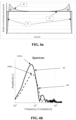
- the Fig. 6b shows a second dotted curve 106 which corresponds to the spectral response of the same sensor fixed on the same mounted assembly for a different static load and a different inflation pressure by having swapped the mounted assembly between the front and rear axles of the vehicle.
- the mechanical response of the pneumatic envelope to its two variables, the inflation pressure and the static load is different.
- the spectral response presents a similarity in terms of shape by a response in the form of successive massifs in the width and the height are a function of the external forces applied to the pneumatic envelope.
- Spectral quantities such as the maximum value, the median value, the average value, the bandwidth, the area under the curve associated with the first massif are all potential criteria for differentiating the deformation of the tire envelope. But also, the frequency of the median value, the frequency of the average value, the frequency of the maximum value are secondary criteria of the deformation of the tire envelope which present a less strong dynamic yet discriminating.
- a deformation value Def % of the tire envelope can then be assigned via a function of one or more spectral quantities in the form of a vector or a scalar which possibly weights the various components of the vector.
- the maximum value 105bis and 106bis of the first massif is a very good indicator of the deformation of the tire envelope, which makes it possible to determine the deformation of the tire envelope through an affine function of the maximum value of the first massif.
- the determination of the deformation of the tire envelope can be more sophisticated by taking into account other spectral quantities also linked to secondary spectral massifs.
- Fig 7 is an illustration of the estimation of the load Z applied to a mounted assembly in rolling condition at rotation speed W.
- the first E1 is a 385/55R22.5 heavy-duty tire mounted on a 22.5-inch steel wheel of the Michelin brand from the X Multiway T range at a wear level D1.
- the second tire E2 is a 315/80R22.5 tire of the Michelin brand from the X Multiway 3D XDE range at a wear level D2.
- Each tire is equipped with an on-board electronic device comprising a single-axis accelerometer positioned at the top, on the side of the inner rubber (in English "inner liner") at the level of a protruding tread element, i.e. different from a longitudinal groove.
- the acquisition frequency of the accelerometer is 1200Hz.
- Each tire undergoes a series of rolling tests in which the travel speed is varied around 20, 40 and 60 km/h at an inflation pressure P varying from 7 to 9 bars in steps of 1 bar.
- the pressure is measured during rolling by means of a pressure sensor here integrated into a TPMS mounted on the wheel valve.
- the load Z applied to the mounted assembly varies between 2000 and 5000 kg in steps of 1 tonne.
Landscapes
- Physics & Mathematics (AREA)
- General Physics & Mathematics (AREA)
- Engineering & Computer Science (AREA)
- Mechanical Engineering (AREA)
- Measuring Fluid Pressure (AREA)
- Tires In General (AREA)
Applications Claiming Priority (2)
| Application Number | Priority Date | Filing Date | Title |
|---|---|---|---|
| FR2108547A FR3126042B1 (fr) | 2021-08-06 | 2021-08-06 | Procédé d’obtention de la charge d’un pneumatique en roulage |
| PCT/FR2022/051540 WO2023012430A1 (fr) | 2021-08-06 | 2022-08-01 | Procede d'obtention de la charge d'un pneumatique en roulage |
Publications (2)
| Publication Number | Publication Date |
|---|---|
| EP4381267A1 EP4381267A1 (fr) | 2024-06-12 |
| EP4381267B1 true EP4381267B1 (fr) | 2025-07-02 |
Family
ID=78049384
Family Applications (1)
| Application Number | Title | Priority Date | Filing Date |
|---|---|---|---|
| EP22758570.0A Active EP4381267B1 (fr) | 2021-08-06 | 2022-08-01 | Procede d'obtention de la charge d'un pneumatique en roulage |
Country Status (9)
| Country | Link |
|---|---|
| US (1) | US20240270032A1 (pl) |
| EP (1) | EP4381267B1 (pl) |
| JP (1) | JP2024532702A (pl) |
| KR (1) | KR20240039134A (pl) |
| CN (1) | CN117751280A (pl) |
| ES (1) | ES3048997T3 (pl) |
| FR (1) | FR3126042B1 (pl) |
| PL (1) | PL4381267T3 (pl) |
| WO (1) | WO2023012430A1 (pl) |
Family Cites Families (4)
| Publication number | Priority date | Publication date | Assignee | Title |
|---|---|---|---|---|
| US9120356B2 (en) * | 2012-06-27 | 2015-09-01 | The Goodyear Tire & Rubber Company | Load estimation system and method for a vehicle tire |
| JP6830873B2 (ja) * | 2017-09-11 | 2021-02-17 | 株式会社ブリヂストン | タイヤ荷重推定方法及びタイヤ荷重推定装置 |
| US12319100B2 (en) * | 2018-12-21 | 2025-06-03 | Compagnie Generale Des Etablissements Michelin | Method for obtaining the deformation of a tire under load when running |
| FR3105759B1 (fr) * | 2019-12-30 | 2022-01-07 | Michelin & Cie | Procédé d’obtention de la CHARGE appliquee à un pneumatique en roulage |
-
2021
- 2021-08-06 FR FR2108547A patent/FR3126042B1/fr active Active
-
2022
- 2022-08-01 KR KR1020247003831A patent/KR20240039134A/ko active Pending
- 2022-08-01 WO PCT/FR2022/051540 patent/WO2023012430A1/fr not_active Ceased
- 2022-08-01 ES ES22758570T patent/ES3048997T3/es active Active
- 2022-08-01 US US18/681,574 patent/US20240270032A1/en active Pending
- 2022-08-01 PL PL22758570.0T patent/PL4381267T3/pl unknown
- 2022-08-01 CN CN202280053288.1A patent/CN117751280A/zh active Pending
- 2022-08-01 JP JP2024506708A patent/JP2024532702A/ja active Pending
- 2022-08-01 EP EP22758570.0A patent/EP4381267B1/fr active Active
Also Published As
| Publication number | Publication date |
|---|---|
| US20240270032A1 (en) | 2024-08-15 |
| PL4381267T3 (pl) | 2025-12-08 |
| CN117751280A (zh) | 2024-03-22 |
| FR3126042B1 (fr) | 2023-07-21 |
| EP4381267A1 (fr) | 2024-06-12 |
| FR3126042A1 (fr) | 2023-02-10 |
| JP2024532702A (ja) | 2024-09-10 |
| ES3048997T3 (en) | 2025-12-12 |
| KR20240039134A (ko) | 2024-03-26 |
| WO2023012430A1 (fr) | 2023-02-09 |
Similar Documents
| Publication | Publication Date | Title |
|---|---|---|
| JP7096871B2 (ja) | 路面状態推定装置及びそれを用いた路面状態推定方法 | |
| EP3681739B1 (fr) | Methode d'evaluation de la fermete d'un sol | |
| EP3898286B1 (fr) | Procede d'obtention de la deformation d'un pneumatique sous charge en roulage | |
| EP3898285B1 (fr) | Procede d'obtention de la deformation d'un pneumatique sous charge en roulage | |
| EP4381267B1 (fr) | Procede d'obtention de la charge d'un pneumatique en roulage | |
| EP3765818A1 (fr) | Procédé de calibration d'un gyromètre équipant un véhicule | |
| EP1789267B1 (fr) | Procédé de détermination d'une condition de roulage par analyse harmonique spatiale de la vitesse | |
| EP4380804B1 (fr) | Methode d'obtention de la deformation d'un pneumatique soumis a une charge en roulage | |
| EP4188722B1 (fr) | Procede d'estimation de l'etat d'usure d'un pneumatique | |
| EP4380805B1 (fr) | Methode d'obtention de la deformation d'un pneumatique soumis a un effort exterieur en roulage | |
| EP4084972B1 (fr) | Procede d'obtention de la charge appliquee a un pneumatique en roulage | |
| WO2023012427A1 (fr) | Methode d'obtention d'un signal representatif de la deformation d'un pneumatique soumis a des forces externes en roulage | |
| EP3898287B1 (fr) | Procédé d'obtention de la deformation d'un pneumatique sous charge en roulage | |
| EP4007889B1 (fr) | Méthode d'estimation de la hauteur d'eau sur une chaussée lors du roulage d'un pneumatique | |
| FR3092224A1 (fr) | Procédé d’obtention de la déformation d’un pneumatique sous charge en roulage |
Legal Events
| Date | Code | Title | Description |
|---|---|---|---|
| STAA | Information on the status of an ep patent application or granted ep patent |
Free format text: STATUS: UNKNOWN |
|
| STAA | Information on the status of an ep patent application or granted ep patent |
Free format text: STATUS: THE INTERNATIONAL PUBLICATION HAS BEEN MADE |
|
| PUAI | Public reference made under article 153(3) epc to a published international application that has entered the european phase |
Free format text: ORIGINAL CODE: 0009012 |
|
| STAA | Information on the status of an ep patent application or granted ep patent |
Free format text: STATUS: REQUEST FOR EXAMINATION WAS MADE |
|
| 17P | Request for examination filed |
Effective date: 20240306 |
|
| AK | Designated contracting states |
Kind code of ref document: A1 Designated state(s): AL AT BE BG CH CY CZ DE DK EE ES FI FR GB GR HR HU IE IS IT LI LT LU LV MC MK MT NL NO PL PT RO RS SE SI SK SM TR |
|
| DAV | Request for validation of the european patent (deleted) | ||
| DAX | Request for extension of the european patent (deleted) | ||
| GRAP | Despatch of communication of intention to grant a patent |
Free format text: ORIGINAL CODE: EPIDOSNIGR1 |
|
| STAA | Information on the status of an ep patent application or granted ep patent |
Free format text: STATUS: GRANT OF PATENT IS INTENDED |
|
| RIC1 | Information provided on ipc code assigned before grant |
Ipc: G01G 19/08 20060101ALI20250131BHEP Ipc: B60C 23/06 20060101ALI20250131BHEP Ipc: G01M 17/02 20060101AFI20250131BHEP |
|
| INTG | Intention to grant announced |
Effective date: 20250220 |
|
| GRAS | Grant fee paid |
Free format text: ORIGINAL CODE: EPIDOSNIGR3 |
|
| GRAA | (expected) grant |
Free format text: ORIGINAL CODE: 0009210 |
|
| STAA | Information on the status of an ep patent application or granted ep patent |
Free format text: STATUS: THE PATENT HAS BEEN GRANTED |
|
| AK | Designated contracting states |
Kind code of ref document: B1 Designated state(s): AL AT BE BG CH CY CZ DE DK EE ES FI FR GB GR HR HU IE IS IT LI LT LU LV MC MK MT NL NO PL PT RO RS SE SI SK SM TR |
|
| REG | Reference to a national code |
Ref country code: GB Ref legal event code: FG4D Free format text: NOT ENGLISH |
|
| REG | Reference to a national code |
Ref country code: CH Ref legal event code: EP |
|
| REG | Reference to a national code |
Ref country code: DE Ref legal event code: R096 Ref document number: 602022017007 Country of ref document: DE |
|
| REG | Reference to a national code |
Ref country code: IE Ref legal event code: FG4D Free format text: LANGUAGE OF EP DOCUMENT: FRENCH |
|
| PGFP | Annual fee paid to national office [announced via postgrant information from national office to epo] |
Ref country code: AT Payment date: 20251020 Year of fee payment: 4 |
|
| REG | Reference to a national code |
Ref country code: NL Ref legal event code: MP Effective date: 20250702 |
|
| PG25 | Lapsed in a contracting state [announced via postgrant information from national office to epo] |
Ref country code: PT Free format text: LAPSE BECAUSE OF FAILURE TO SUBMIT A TRANSLATION OF THE DESCRIPTION OR TO PAY THE FEE WITHIN THE PRESCRIBED TIME-LIMIT Effective date: 20251103 |
|
| REG | Reference to a national code |
Ref country code: ES Ref legal event code: FG2A Ref document number: 3048997 Country of ref document: ES Kind code of ref document: T3 Effective date: 20251212 |
|
| PG25 | Lapsed in a contracting state [announced via postgrant information from national office to epo] |
Ref country code: NL Free format text: LAPSE BECAUSE OF FAILURE TO SUBMIT A TRANSLATION OF THE DESCRIPTION OR TO PAY THE FEE WITHIN THE PRESCRIBED TIME-LIMIT Effective date: 20250702 |
|
| REG | Reference to a national code |
Ref country code: AT Ref legal event code: MK05 Ref document number: 1809705 Country of ref document: AT Kind code of ref document: T Effective date: 20250702 |
|
| PG25 | Lapsed in a contracting state [announced via postgrant information from national office to epo] |
Ref country code: IS Free format text: LAPSE BECAUSE OF FAILURE TO SUBMIT A TRANSLATION OF THE DESCRIPTION OR TO PAY THE FEE WITHIN THE PRESCRIBED TIME-LIMIT Effective date: 20251102 |
|
| PGFP | Annual fee paid to national office [announced via postgrant information from national office to epo] |
Ref country code: DE Payment date: 20251021 Year of fee payment: 4 |
|
| PG25 | Lapsed in a contracting state [announced via postgrant information from national office to epo] |
Ref country code: NO Free format text: LAPSE BECAUSE OF FAILURE TO SUBMIT A TRANSLATION OF THE DESCRIPTION OR TO PAY THE FEE WITHIN THE PRESCRIBED TIME-LIMIT Effective date: 20251002 |
|
| REG | Reference to a national code |
Ref country code: LT Ref legal event code: MG9D |
|
| PG25 | Lapsed in a contracting state [announced via postgrant information from national office to epo] |
Ref country code: AT Free format text: LAPSE BECAUSE OF FAILURE TO SUBMIT A TRANSLATION OF THE DESCRIPTION OR TO PAY THE FEE WITHIN THE PRESCRIBED TIME-LIMIT Effective date: 20250702 |
|
| PG25 | Lapsed in a contracting state [announced via postgrant information from national office to epo] |
Ref country code: FI Free format text: LAPSE BECAUSE OF FAILURE TO SUBMIT A TRANSLATION OF THE DESCRIPTION OR TO PAY THE FEE WITHIN THE PRESCRIBED TIME-LIMIT Effective date: 20250702 |
|
| PG25 | Lapsed in a contracting state [announced via postgrant information from national office to epo] |
Ref country code: HR Free format text: LAPSE BECAUSE OF FAILURE TO SUBMIT A TRANSLATION OF THE DESCRIPTION OR TO PAY THE FEE WITHIN THE PRESCRIBED TIME-LIMIT Effective date: 20250702 |
|
| PG25 | Lapsed in a contracting state [announced via postgrant information from national office to epo] |
Ref country code: GR Free format text: LAPSE BECAUSE OF FAILURE TO SUBMIT A TRANSLATION OF THE DESCRIPTION OR TO PAY THE FEE WITHIN THE PRESCRIBED TIME-LIMIT Effective date: 20251003 |
|
| PG25 | Lapsed in a contracting state [announced via postgrant information from national office to epo] |
Ref country code: CZ Free format text: LAPSE BECAUSE OF FAILURE TO SUBMIT A TRANSLATION OF THE DESCRIPTION OR TO PAY THE FEE WITHIN THE PRESCRIBED TIME-LIMIT Effective date: 20250702 Ref country code: SE Free format text: LAPSE BECAUSE OF FAILURE TO SUBMIT A TRANSLATION OF THE DESCRIPTION OR TO PAY THE FEE WITHIN THE PRESCRIBED TIME-LIMIT Effective date: 20250702 |
|
| PG25 | Lapsed in a contracting state [announced via postgrant information from national office to epo] |
Ref country code: LV Free format text: LAPSE BECAUSE OF FAILURE TO SUBMIT A TRANSLATION OF THE DESCRIPTION OR TO PAY THE FEE WITHIN THE PRESCRIBED TIME-LIMIT Effective date: 20250702 |
|
| PG25 | Lapsed in a contracting state [announced via postgrant information from national office to epo] |
Ref country code: BG Free format text: LAPSE BECAUSE OF FAILURE TO SUBMIT A TRANSLATION OF THE DESCRIPTION OR TO PAY THE FEE WITHIN THE PRESCRIBED TIME-LIMIT Effective date: 20250702 |
|
| PGFP | Annual fee paid to national office [announced via postgrant information from national office to epo] |
Ref country code: PL Payment date: 20251020 Year of fee payment: 4 |
|
| PG25 | Lapsed in a contracting state [announced via postgrant information from national office to epo] |
Ref country code: RS Free format text: LAPSE BECAUSE OF FAILURE TO SUBMIT A TRANSLATION OF THE DESCRIPTION OR TO PAY THE FEE WITHIN THE PRESCRIBED TIME-LIMIT Effective date: 20251002 |
|
| PGFP | Annual fee paid to national office [announced via postgrant information from national office to epo] |
Ref country code: ES Payment date: 20251030 Year of fee payment: 4 |