EP4381239B1 - Energiespeichervorrichtung - Google Patents
Energiespeichervorrichtung Download PDFInfo
- Publication number
- EP4381239B1 EP4381239B1 EP22760950.0A EP22760950A EP4381239B1 EP 4381239 B1 EP4381239 B1 EP 4381239B1 EP 22760950 A EP22760950 A EP 22760950A EP 4381239 B1 EP4381239 B1 EP 4381239B1
- Authority
- EP
- European Patent Office
- Prior art keywords
- heat transfer
- energy storage
- thermal energy
- storage device
- powder bed
- Prior art date
- Legal status (The legal status is an assumption and is not a legal conclusion. Google has not performed a legal analysis and makes no representation as to the accuracy of the status listed.)
- Active
Links
Images


Classifications
-
- F—MECHANICAL ENGINEERING; LIGHTING; HEATING; WEAPONS; BLASTING
- F28—HEAT EXCHANGE IN GENERAL
- F28D—HEAT-EXCHANGE APPARATUS, NOT PROVIDED FOR IN ANOTHER SUBCLASS, IN WHICH THE HEAT-EXCHANGE MEDIA DO NOT COME INTO DIRECT CONTACT
- F28D20/00—Heat storage plants or apparatus in general; Regenerative heat-exchange apparatus not covered by groups F28D17/00 or F28D19/00
- F28D20/0056—Heat storage plants or apparatus in general; Regenerative heat-exchange apparatus not covered by groups F28D17/00 or F28D19/00 using solid heat storage material
-
- F—MECHANICAL ENGINEERING; LIGHTING; HEATING; WEAPONS; BLASTING
- F28—HEAT EXCHANGE IN GENERAL
- F28D—HEAT-EXCHANGE APPARATUS, NOT PROVIDED FOR IN ANOTHER SUBCLASS, IN WHICH THE HEAT-EXCHANGE MEDIA DO NOT COME INTO DIRECT CONTACT
- F28D20/00—Heat storage plants or apparatus in general; Regenerative heat-exchange apparatus not covered by groups F28D17/00 or F28D19/00
- F28D20/02—Heat storage plants or apparatus in general; Regenerative heat-exchange apparatus not covered by groups F28D17/00 or F28D19/00 using latent heat
- F28D20/021—Heat storage plants or apparatus in general; Regenerative heat-exchange apparatus not covered by groups F28D17/00 or F28D19/00 using latent heat the latent heat storage material and the heat-exchanging means being enclosed in one container
-
- H—ELECTRICITY
- H02—GENERATION; CONVERSION OR DISTRIBUTION OF ELECTRIC POWER
- H02J—CIRCUIT ARRANGEMENTS OR SYSTEMS FOR SUPPLYING OR DISTRIBUTING ELECTRIC POWER; SYSTEMS FOR STORING ELECTRIC ENERGY
- H02J15/00—Systems for storing electric energy
-
- F—MECHANICAL ENGINEERING; LIGHTING; HEATING; WEAPONS; BLASTING
- F28—HEAT EXCHANGE IN GENERAL
- F28D—HEAT-EXCHANGE APPARATUS, NOT PROVIDED FOR IN ANOTHER SUBCLASS, IN WHICH THE HEAT-EXCHANGE MEDIA DO NOT COME INTO DIRECT CONTACT
- F28D20/00—Heat storage plants or apparatus in general; Regenerative heat-exchange apparatus not covered by groups F28D17/00 or F28D19/00
- F28D20/0034—Heat storage plants or apparatus in general; Regenerative heat-exchange apparatus not covered by groups F28D17/00 or F28D19/00 using liquid heat storage material
- F28D2020/0047—Heat storage plants or apparatus in general; Regenerative heat-exchange apparatus not covered by groups F28D17/00 or F28D19/00 using liquid heat storage material using molten salts or liquid metals
-
- Y—GENERAL TAGGING OF NEW TECHNOLOGICAL DEVELOPMENTS; GENERAL TAGGING OF CROSS-SECTIONAL TECHNOLOGIES SPANNING OVER SEVERAL SECTIONS OF THE IPC; TECHNICAL SUBJECTS COVERED BY FORMER USPC CROSS-REFERENCE ART COLLECTIONS [XRACs] AND DIGESTS
- Y02—TECHNOLOGIES OR APPLICATIONS FOR MITIGATION OR ADAPTATION AGAINST CLIMATE CHANGE
- Y02E—REDUCTION OF GREENHOUSE GAS [GHG] EMISSIONS, RELATED TO ENERGY GENERATION, TRANSMISSION OR DISTRIBUTION
- Y02E60/00—Enabling technologies; Technologies with a potential or indirect contribution to GHG emissions mitigation
- Y02E60/14—Thermal energy storage
-
- Y—GENERAL TAGGING OF NEW TECHNOLOGICAL DEVELOPMENTS; GENERAL TAGGING OF CROSS-SECTIONAL TECHNOLOGIES SPANNING OVER SEVERAL SECTIONS OF THE IPC; TECHNICAL SUBJECTS COVERED BY FORMER USPC CROSS-REFERENCE ART COLLECTIONS [XRACs] AND DIGESTS
- Y02—TECHNOLOGIES OR APPLICATIONS FOR MITIGATION OR ADAPTATION AGAINST CLIMATE CHANGE
- Y02E—REDUCTION OF GREENHOUSE GAS [GHG] EMISSIONS, RELATED TO ENERGY GENERATION, TRANSMISSION OR DISTRIBUTION
- Y02E70/00—Other energy conversion or management systems reducing GHG emissions
- Y02E70/30—Systems combining energy storage with energy generation of non-fossil origin
Definitions
- This invention relates to a thermal energy storage device.
- thermal energy storage may be used for balancing of energy demand over time.
- thermal energy storage some medium is heated electrically when there is a surplus of electrical energy available.
- demand exceeds supply the stored heat may be used to generate steam which can be used as a power source itself or converted into electricity using a steam turbine generator.
- the materials used for storing the thermal energy are preferably inexpensive and safe.
- One of the cheapest, most commonly used options is a water tank, but materials such as molten salts, sand, or metals can be heated to higher temperatures and therefore offer a higher storage capacity or higher levels of useful energy.
- thermal energy storage systems A common drawback of many currently available thermal energy storage systems is that some form of system is needed to convert the electrical energy produced by, e.g. the wind turbines or solar panels, into thermal energy stored in the storage medium.
- the international patent application WO 2020/254001 A1 describes the use of an electrical heating device for heating the thermal storage medium.
- the storage medium is an electrically conductive medium with a low electrical resistivity of between 10- 4 ⁇ m and 1 ⁇ m.
- the electrical heating device uses an induction coil to store electrical energy in the form of heat.
- the electrical heating device uses contact electrodes to generate an electric current within the material and thereby heat the thermal energy storage medium.
- the heating device of WO 2020/254001 A1 Even when heating the heat storage medium by direct contact with the contact electrodes, the heating device of WO 2020/254001 A1 still requires large and expensive transformers for first converting the high voltage of the electrical distribution grid that is fed by electricity from renewable energy sources to a much lower voltage that can be used for heating the electrically conductive medium with a low electrical resistivity.
- thermo energy storage device comprising:
- a thermal energy storage device which comprises a powder bed, at least two electrodes, and at least one heat transfer tube.
- the powder bed has an electrical resistivity in the range of between 500 ⁇ m and 50,000 ⁇ m.
- the at least two electrodes are embedded in the powder bed and arranged to heat the powder bed by providing an electrical current between the electrodes.
- the at least one heat transfer tube is arranged to contain a heat transfer fluid and has an inlet and an outlet connectable to a thermal energy consumer.
- the heat transfer tube and the powder bed are thermally coupled via an electrically insulating material.
- the electrical resistivity of the powder bed may advantageously be selected such that the thermal energy storage device can be connected directly to an electric energy supply without requiring the use of any transformers for first converting the high voltage of the electric energy supply to a much lower voltage that can be used for heating the electrically conductive medium between the electrodes.
- Such a direct connection to the electrical energy source allows the powder bed to simultaneously fulfil the functions of energy conversion and energy storage. This results not only in a significant cost reduction, but in better control over local peak temperatures too, thereby increasing the durability and the lifetime of the system.
- the heating power of the electrodes is proportional to the resistance of the powder bed and the electrical current squared. According to Ohm's law, this can also be expressed as proportional to the electrical voltage squared and divided by the electrical resistance.
- the electrical resistance provided by the powder bed is proportional to the resistivity of the powder bed material and the electrode separation. With the above-mentioned preferred resistivity in the range of between 500 ⁇ m and 50,000 ⁇ m, practical electrode separations of, for example, from 50 cm to 200 cm may be used to achieve a suitable heating power and to heat the powder bed to suitable temperatures.
- semiconducting particles are used for the powder bed.
- the use of semiconductor material in powdered form allows for free thermal expansion of the electrodes and the powder bed during the heating process.
- the powder bed may self-heal under the influence of its own weight.
- a good contact between the electrodes and the semi-conductor material is ensured for many repeated energy storage and release cycles.
- the semiconductor material of the powder bed comprises a silicon carbide matrix.
- the silicon carbide matrix may be undoped or doped.
- the silicon carbide matrix may be doped with nitrogen, phosphorus, beryllium, boron, aluminium, or gallium, or combinations thereof.
- An advantage of using silicon carbide particles is that it is a readily available bulk material that can be used in powdered form without requiring any post processing steps like sintering.
- the doped silicon carbide may, for example, have a very suitable electrical resistivity of about 1,000 ⁇ m. It is noted that the resistivity of the powder bed does not only depend on the material of the particles used, but also on, e.g., particle size, particle shape, and the spacing between the particles.
- the electrodes are in direct contact with the powder bed to ensure an efficient and effective heat transfer.
- the electrodes comprise graphite or sintered silicon carbide which provides for a good conductivity and longevity.
- the electrically insulating material is an electrically insulating layer of a bulk material Suitable bulk materials include selected grades of silicon carbide (preferably undoped), sand, quartz, and iron ore.
- the heat transfer tube may be embedded in the bulk material.
- particulate bulk material is preferred, alternative solid, possibly porous, materials may be used as an alternative.
- concrete may be a suitable material in terms of cost, electrical insulation, and thermal conduction.
- the thermal energy storage device comprises a plurality of thermally coupled modules, each module including:
- Some of the exemplary thermal energy storage devices described above may further comprise a buffer, thermally coupled to the powder bed and separated from the heat transfer tube by at least the powder bed.
- a buffer may further increase the total storage capacity of the thermal energy storage device and may help to control the maximum temperature of the heat generating powder bed.
- the buffer may comprise a material that stores energy in the form of sensible heat, or in the form of latent heat, or in a combination of both.
- the thermal energy storage device may comprise a plurality of thermally coupled modules, each module including:
- Preferred thermal energy storage devices may further comprise a thermally insulating bottom layer, supporting at least the powder bed, the heat transfer tube, and the electrically insulating material.
- a bottom insulation layer helps to prevent a loss of heat to the soil on which the thermal energy storage device is placed.
- a top insulation layer may be added to prevent a loss of heat to the air above the thermal energy storage device. Additional insulation may be provided at one or more sides of the thermal energy storage device. All insulation layers can be made of any suitable thermally insulating material.
- mineral wool an inexpensive bulk material is used, for example one of the bulk materials already discussed above. Possible materials include, but are not limited to mineral wool, ceramic foams, vacuum panels, or beds of granulated insulation materials, such as sand, quartz, pumice, or volcanic ash.
- the top and/or bottom insulation layers may further comprise a cooling tube, embedded in the thermally insulating bottom layer.
- the cooling tube may be filled with a cooling fluid, such as water, to take up some of the heat that would otherwise have warmed the soil underneath the thermal energy storage device.
- the cooling tube may be connected to a pump for providing a continuous supply of cool cooling fluid.
- the cooling tube may further be connected to the inlet of the heat transfer tube, such that it can be used to preheat the heat transfer fluid.
- the thermal energy storage devices described herein above may be used in method of heating a heat transfer fluid, wherein passing an electrical current between the at least two electrodes whereby generating heat in the powder bed and thereby heating said electrically insulation material, and passing the heat transfer fluid through the at least one heat transfer tube whereby heating the heat transfer fluid with heat from the electrically insulation material.
- the electric current may be fluctuating over time, such as is frequently the case when the electric current is derived from a renewable source such as a solar and/or wind power source.
- the electrically insulating material and the optional buffer layer act as a thermal buffer which continues to heat up the heat transfer fluid for a certain amount of time during an interruption of the electric current when no, or insufficient, electric power is available to replenish the heat that is being extracted from the device.
- FIG. 1 schematically illustrates a wind farm 10, a solar farm 20, and a thermal energy storage device 100.
- the thermal energy storage device 100 When there is a suitable amount of wind, the rotating rotor blades of the wind turbines 11 in the wind farm 10 drive a generator that produces electricity. Similarly, during the day, solar panels 21 in the solar farm 20 absorb light from the sun 50 and generate electricity too. The wind farm 10 and the solar farm 20 are both electrically connected to the thermal energy storage device 100.
- the purpose of the thermal energy storage device 100 is to store the electric energy generated by the wind farm 10 and solar farm 20 by heating up a storage medium. The stored energy is released when needed by heating a heat transfer fluid.
- the heated heat transfer fluid typically water in the form of steam
- a thermal energy consumer here symbolised by a factory 30.
- the consumer may, for example, use the steam directly in some industrial process, or use a steam turbine generator to first convert the steam into electric power before supplying the steam to an industrial process or alternatively a steam condenser.
- a return flow of the heat transfer fluid (at least a portion thereof) may be cycled back to the thermal energy storage device 100 for further extracting heat therefrom.
- FIG. 2 shows a perspective view of an embodiment of the thermal energy storage device 100.
- the thermal energy storage device 100 is made up of a series of alternating layers 110, 120, 130 with different functions, materials, and other features.
- the layers may extend vertically and/or form columns.
- An electrical current passing through the electrode layer 110 is converted into thermal energy causing the material in this layer 110 to warm up to temperatures that may, for example, exceed 800°C.
- a tube structure 200 is provided through which a heat transfer liquid, for example water, may be led to receive some of the stored energy and become a heated fluid in the form of, e.g., steam.
- a heat transfer liquid for example water
- a larger storage capacity and improved control over the local peak temperature, and energy storage and release process is obtained by providing a plurality of such layers in an alternating pattern.
- Optional buffer layers 130 may be added for further increasing the total storage capacity of and controlling the maximum temperature and release duty variation in the thermal energy storage device 100.
- the electrode layer 110 comprises a powder bed of a semiconductor material providing the powder bed an electrical resistivity of in the range of 500-50,000 ⁇ m. At least two electrodes are embedded in the powder bed and arranged to heat the powder bed by providing a voltage therebetween.
- the semiconductor material may, for example, comprise silicon carbide (SiC), optionally doped with a suitable amount of nitrogen, phosphorus, beryllium, boron, aluminium, or gallium to obtain the desired electrical resistivity.
- Doped silicon carbide has excellent electrical and thermal properties (in terms of conductance and storage capacity) for use in the electrode layer 110 of the thermal energy storage device 100. Such doped silicon carbide may, e.g., have an electrical resistivity of about 1,000 ⁇ m for use with an intermediate transmission grid supply voltage.
- undoped silicon carbide may be suitable for use as the main ingredient of the powder bed too.
- Undoped silicon carbide with a resistivity of up to 50,000 ⁇ m may, for example, be used with a high transmission grid supply voltage.
- the resistivity of the powder bed does not only depend on the material of the powder bed particles used, but also on, e.g., particle size, particle shape, and the spacing between the particles.
- the electrical resistivity of the powder bed is preferably selected in such a way that the thermal energy storage device 100 can be connected directly to an electric energy supply, such as the wind farm 10 or the solar farm 20, without requiring the use of any transformers for first converting the high voltage of the electric energy supply to a much lower voltage that can be used for heating the electrically conductive medium between the electrodes.
- an electric energy supply such as the wind farm 10 or the solar farm 20
- Such a direct connection to the electrical energy source allows the selected semiconductor material to simultaneously fulfil the functions of energy conversion and energy storage. This results in a significant cost reduction.
- a further advantage of using silicon carbide is that it is a readily available bulk material that can be used in powdered form without requiring any post processing steps like sintering.
- the use of semiconductor material in powdered form also allows for free thermal expansion of the electrodes during the heating process. When the electrodes contract while cooling down, the powder bed may self-heal under the influence of its own weight. Thus, a good contact between the electrodes and the semi-conductor material are ensured for many repeated energy storage and release cycles.
- Degradation of the electrical properties of silicon carbide over time due to the prolonged exposure to high temperatures can be minimised by controlling the peak temperature in the heat generating layer, for example by limiting the peak temperature to about 800 °C.
- Other ways to limit degradation of the powder bed material include the choice of particle size and periodic injection of a protective purge gas (e.g., nitrogen, argon, or carbon dioxide).
- a preferred choice of material for the electrodes 301, 302, 303 is graphite or sintered silicon carbide. Both graphite and sintered silicon carbide electrodes have a good electrical conductivity and longevity.
- the electrodes 301, 302, 303 may be directly connected to a high-voltage power source.
- the voltage of such high-voltage power source may exceed 1 kV (1,000 Volts), 5 kV, or 10 kV.
- the wind farm 10 and/or solar farm 20 may provide a 33 kV voltage employing a three-phase alternating current.
- a first line of interconnected first electrodes 301 may be connected to a first phase
- a second line of interconnected second electrodes 302 may be connected to a second phase
- a third line of interconnected third electrodes 303 may be connected to a third phase.
- This pattern may the repeat for fourth, fifth, sixth, and subsequent lines of interconnected electrodes.
- lower or higher voltages e.g., 6kV, 11 kV, 22 kV, 66kV
- a two-phase alternating current e.g., 6kV, 11 kV, 22 kV, 66kV
- Electrode layer 110 will warm up as a result of its ohmic resistance. The highest heating (and thus temperatures, possibly up to more than 800°C) is expected to occur near the electrodes 301, 302, 303.
- the electrical and heat conducting properties and heat storage capacity of the semiconductor material will determine the further distribution of the generated heat through the electrode layer 110.
- the heat release layer 120 is provided adjacent the electrode layer 110 and either in direct contact therewith or in contact with an intermediate buffer layer that may comprise a different material than the electrode layer 110 and the heat release layer 120.
- the heat conductance and heat storage properties of the material used for this heat release layer are such that heat generated in the electrode layer 110 is effectively transferred to the heat transfer tube 200.
- One function of the heat release layer 120 is to dampen out the daily or hourly intermittency of the renewable energy supply in order to provide an acceptable heat supply variation to the consumer.
- the heat transfer tube 200 is made of a material that shrinks and expands under the influence of a change in temperature, it is preferred that the material used for the heat release layer 120 can accommodate these changes.
- the use of a bulk material consisting of loose particles, such as a powder, is preferred.
- Suitable materials that may be used for the heat release layer 120 include bulk material, such as (nonconducting) silicon carbide, sand, quartz, or iron ore. If the heat transfer tube 200 is made of an electrically conductive material, such as a metal, the material used for the heat release layer 120 is preferably not electrically conductive, such as to electrically insulate the heat transfer tube 200 and to avoid undesirable electrical currents running through it. Alternatively, the heat release layer 120 may comprise the same semiconductor material as is used for the electrode layer 110, or another electrically conductive or semi-conductive material. In that event, an insulation layer may be applied to the heat transfer tube 200 to avoid undesirable electrical currents running through it.
- electrical insulation layers may be provided in between the electrode layer 110 and the heat release layer 120, thereby creating an opportunity to use electrically conductive material for the heat release layer 120.
- an additional buffer layer 130 is provided for further increasing the total storage capacity of the thermal energy storage device 100 and controlling the maximum temperature.
- a material is selected based on, e.g., cost, heat conductance, and heat storage capacity.
- Suitable materials for use in this buffer layer include bulk material, such as (nonconducting) silicon carbide, sand, quartz, iron ore, or materials capable of storing latent heat, possibly in combination with sensible heat, such as miscibility gap alloys (MGA), solar salt or low-melting metals, conceivably comingled with a non-melting porous or bulk solid.
- the buffer layer 130 may, as in Figure 2 , be sandwiched between two electrode layers 110, but alternative arrangements leaving out one or two of the adjacent electrode layers 110, or adding more electrically insulating layers, are possible too.
- All layers may be purged periodically or continuously, for example, using nitrogen, argon, or carbon dioxide to prevent degradation of desirable properties or moisture accumulation in the layers and/or around the electrodes 301, 302, 303 or heat transfer tubes 200.
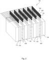
- FIG 3 shows an example of a heat transfer tube 200 for use in the thermal energy storage device of Figure 2 .
- the heat transfer tube 200 comprises a plurality of substantially parallel straight sections 230 that are connected to each other by interconnecting sections 240.
- the interconnecting sections 240 may, e.g., be curved, flanged, or executed as cross fittings.
- W water
- S steam
- a pump (not shown) may be provided for pumping the water into the inlet 210.
- the steam After leaving the outlet 220, the steam, typically at a temperature of about 350°C, may be led to one or more consumers.
- the consumer may, for example, use the steam directly in some industrial process, or use a steam turbine generator to first convert the steam into electric power.
- the heat transfer tube 200 and the consumer form a closed circuit, wherein the used steam is condensed into water and pumped back to the inlet 210 of the heat transfer tube 200.
- each inlet 210 may be connected to its own supply of heat transfer fluid and the heat transfer fluid may have a similar temperature at every inlet 210.
- two or more heat transfer tubes 200 may be interconnected such that the outlet 220 of a first heat transfer tube 200 is connected to an inlet 210 of a second heat transfer tube 200, and that the heat transfer fluid passes through the two or more heat transfer tubes before it leaves the thermal heat storage device 100 and is sent to a consumer.
- the heat transfer tube 200 may be made of a metal, such as stainless steel.
- An important property of the material to be used for the heat transfer tube 200 is that it allows for an efficient heat exchange between the heat release layer 120 at its outside and the heat transfer fluid at its inside. Permanent contact between the heat transfer tube 200 and the heat release layer 120 can be promoted by using a granular material that freely expands or contracts relative to the tube. As already explained above, if the tube material is electrically conductive it is important that some form of electrical insulation is provided to insulate the heat transfer tube 200 from the electrodes 301, 302, 303. In addition, earthing and bonding of the heat transfer tube may be provided.
- one or more of the interconnecting sections 240 of the heat transfer tube 200 can easily be demounted from and remounted to the straight sections 230.
- the interconnecting sections 240 protrude from the main body of the thermal energy storage device 100, demounting the interconnecting sections 240 allows for maintenance and inspection access to the horizontally placed straight sections 230 of the heat transfer tube 200.
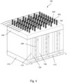
- FIG 4 shows the thermal energy storage device 100 of Figure 2 with added thermal insulation.
- a bottom insulation layer 410 helps to prevent a loss of heat to the soil on which the thermal energy storage device 100 is placed.
- the bottom insulation layer 410 can be made of any suitable thermally insulating material. Preferably, an inexpensive bulk material with good thermal insulation and load-bearing properties is used. Possible materials include, but are not limited to, sand, quartz, pumice, or volcanic ash.
- the bottom insulation layer 410 may include a cooling tube 412 that can be filled with a cooling fluid, such as water, to take up some of the heat that would otherwise have warmed the soil underneath the thermal energy storage device 100.
- the cooling tube 412 may be made of similar materials as the heat transfer tube 200. Preferably the cooling tube 412 is connected to a pump for providing a continuous supply of cool cooling fluid.
- the cooling tube 412 may be connected to the inlet 210 of the heat transfer tube 200, such that it can be used to preheat the heat transfer fluid.
- a similar top insulation layer 420 may be provided on top of the thermal energy storage device 100 in order to prevent excessive heat loss to the direct environment.
- the top insulation layer 420 may comprise the same or similar materials as the bottom insulation layer 410.
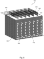
- FIG. 5 shows a perspective view of a different embodiment of the thermal energy storage device 100.
- the main difference with the thermal energy storage device 100 shown in Figure 4 is that it does not comprise any buffer layers 130, but a repeating pattern of alternating electrode layers 110 and heat release layers 120.
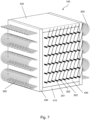
- FIG 6 shows the thermal energy storage device 100 of Figure 5 with more added thermal insulation.
- a thermal insulation sleeve 500 is applied to all side walls of the thermal energy storage device 100.
- Many readily available thermal insulation materials may be used for this thermal insulation sleeve 500.
- perlite may be used because of its suitability for high temperatures.
- the possibility to add such an insulation sleeve 500 is not limited to the embodiment of Figure 5 , but may also be beneficial in other embodiments, such as those of Figures 2 and 4 .
- the sides of the thermal energy storage device 100 may have vertical walls, or may be unwalled, following the natural angle of repose of the bulk material.
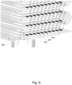
- Figure 7 shows a perspective view of an alternative embodiment of the thermal energy storage device 100.
- Figure 8 shows a close-up of part of the thermal energy storage device 100 of Figure 7 with its external insulation layers 410, 420, 430 removed.
- Many features of this embodiment are similar to and perform the same function as corresponding features in the embodiments described above with reference to Figures 2 to 6 . Therefore, the same reference numbers are used for such corresponding features.
- the different layers 110, 120, 130, 140 have a substantially horizontal orientation. It is noted that the use of such a layered configuration may be advantageous for reasons of performance and/or ease of construction, but that the invention is not limited to such a configuration. Also, when layers are used, their orientations may differ from the substantially vertical or horizontal orientations shown in the drawings. Likely, the layers may have varying thickness and different shapes. For example, a cylindrical thermal energy storage device may be provided wherein the different layers are provided as concentric rings.
- the first, second and third electrodes 301, 302, 303 are aligned in parallel in a substantially horizontal electrode layer 110 that is sandwiched between two substantially horizontal electrically insulating layers 140, filled with, e.g., one of the electrically insulating bulk materials described above.
- An important function of these electrically insulating layers 140 is that they allow for the use of electrically conducting materials for the subsequent buffer layer 130 and heat release layer 120.
- the buffer layer 130 and/or heat release layer 120 may be made up of the same or different materials. All materials mentioned above for the corresponding layers 120, 130 in the embodiments described in Figures 2 to 6 can be used in this embodiment too.
- the maximum temperature fluctuation between day and night in the heat generating electrode layer 110 is about 100°C (e.g. cycling between 700°C and 800 °C).
- a primary function of the heat release layer 120 is to dampen the day-night variation of the duty output to the consumer. This can be achieved by reducing the temperature swing in the heat generating electrode layer 110.
- one or both layers 120, 130 may comprise a phase change material that can store energy in the form of latent heat. If the layer composition is such that part of it changes phase, e.g. by melting during a heating cycle and solidifying when less renewable energy is produced and the layer cools down, a more constant temperature buffer is obtained. This helps to prevent overheating of the steam tubes during periods of low consumer demand.
- phase change material When using phase change material, it is important that it remains stationary within the layer 120 when in the molten state. This may, for example, be achieved by mixing a low-melting granulate with a non-melting bulk material (i.e., a bulk material with a melting temperature high enough to avoid melting during normal use of the thermal energy storage device 100). Possible combinations are 50%-50% mixtures of either magnesium (phase change at 650°C) and iron (phase change at 1538 °C), or zinc (phase change at 420°C) and graphite (phase change at 3600°C), or an aluminium magnesium eutectic and either pure or mixtures of sand, silicon carbide, iron ore or graphite.
- a non-melting bulk material i.e., a bulk material with a melting temperature high enough to avoid melting during normal use of the thermal energy storage device 100.
- Possible combinations are 50%-50% mixtures of either magnesium (phase change at 650°C) and iron (phase change at 1538 °C), or zinc (
- phase change materials comprising metals are electrically conductive
- the electrically insulating layer 140 is provided for electrical insulation between the electrode layer 110 and the steam tubes 200.
Landscapes
- Engineering & Computer Science (AREA)
- Physics & Mathematics (AREA)
- Thermal Sciences (AREA)
- Mechanical Engineering (AREA)
- General Engineering & Computer Science (AREA)
- Power Engineering (AREA)
- Resistance Heating (AREA)
- Pipe Accessories (AREA)
Claims (15)
- Wärmeenergiespeichervorrichtung (100), umfassend:- ein Pulverbett, das einen spezifischen elektrischen Widerstand in einem Bereich zwischen 500 Ωm und 50.000 Ωm aufweist;- mindestens zwei Elektroden (301, 302, 303), die in das Pulverbett eingebettet und angeordnet sind, um das Pulverbett zu erwärmen, durch ein Bereitstellen eines elektrischen Stroms dazwischen; und- mindestens ein Wärmeübertragungsrohr (200), das angeordnet ist, um ein Wärmeübertragungsfluid zu enthalten, wobei das Wärmeübertragungsrohr einen Einlass und einen Auslass aufweist, die mit einem Wärmeenergieverbraucher verbindbar sind, wobei das Wärmeübertragungsrohr und das Pulverbett über ein elektrisch isolierendes Material thermisch gekoppelt sind.
- Wärmeenergiespeichervorrichtung nach Anspruch 1, wobei das Pulverbett ein Halbleitermaterial umfasst.
- Wärmeenergiespeichervorrichtung nach Anspruch 2, wobei das Halbleitermaterial eine Siliziumkarbidmatrix umfasst, undotiert oder dotiert mit Stickstoff, Phosphor, Beryllium, Bor, Aluminium oder Gallium.
- Wärmeenergiespeichervorrichtung nach Anspruch 1 oder 2, wobei die Elektroden in direktem Kontakt mit dem Pulverbett stehen.
- Wärmeenergiespeichervorrichtung nach einem der Ansprüche 1 bis 4, wobei die Elektroden Graphit oder gesintertes Siliziumkarbid umfassen.
- Wärmeenergiespeichervorrichtung nach einem der Ansprüche 1 bis 5, wobei das elektrisch isolierende Material eine elektrisch isolierende Schicht aus einem Schüttmaterial wie Siliziumkarbid, Sand, Quarz oder Eisenerz ist, wobei das Wärmeübertragungsrohr in das Schüttmaterial eingebettet ist.
- Wärmeenergiespeichervorrichtung nach einem der Ansprüche 1 bis 6, umfassend eine Vielzahl von thermisch gekoppelten Modulen, wobei jedes Modul einschließt:- eine wärmeerzeugende Schicht, umfassend das Pulverbett und die mindestens zwei Elektroden; und- eine Wärmeabgabeschicht, umfassend das Wärmeübertragungsrohr und das elektrisch isolierende Material.
- Wärmeenergiespeichervorrichtung nach einem der Ansprüche 1 bis 7, ferner umfassend eine Pufferschicht, die mit dem Pulverbett thermisch gekoppelt und von dem Wärmeübertragungsrohr mindestens durch das Pulverbett getrennt ist.
- Wärmeenergiespeichervorrichtung nach Anspruch 8, wobei die Pufferschicht ein Phasenwechselmaterial umfasst.
- Wärmeenergiespeichervorrichtung nach Anspruch 8 oder 9, umfassend eine Vielzahl von thermisch gekoppelten Modulen, wobei jedes Modul einschließt:- eine erste Wärmeerzeugungsschicht, umfassend das Pulverbett und die mindestens zwei Elektroden;- eine Wärmeabgabeschicht, umfassend das Wärmeübertragungsrohr und das elektrisch isolierende Material;- eine zweite Wärmeerzeugungsschicht, umfassend das Pulverbett und die mindestens zwei Elektroden; und- die Pufferschicht.
- Wärmeenergiespeichervorrichtung nach einem der Ansprüche 1 bis 10, ferner umfassend eine thermisch isolierende Bodenschicht, die mindestens das Pulverbett, das Wärmeübertragungsrohr und das elektrisch isolierende Material trägt.
- Wärmeenergiespeichervorrichtung nach Anspruch 11, ferner umfassend ein Kühlrohr, das in die thermisch isolierende Bodenschicht eingebettet ist, wobei das Kühlrohr mit dem Wärmeübertragungsrohr verbindbar ist.
- Wärmeenergiespeichervorrichtung nach einem der Ansprüche 1 bis 12, wobei die mindestens zwei Elektroden mit einer Hochspannungsquelle direkt verbunden sind, deren Spannung 1.000 Volt übersteigt.
- Verfahren zum Erwärmen eines Wärmeübertragungsfluids, umfassend:- Bereitstellen einer Wärmeenergiespeichervorrichtung (100) wie in einem der vorstehenden Ansprüche definiert, umfassend ein Pulverbett, mindestens zwei Elektroden (301, 302, 303) und mindestens ein Wärmeübertragungsrohr (200), das über ein elektrisch isolierendes Material mit dem Pulverbett thermisch gekoppelt ist;- Leiten eines elektrischen Stroms zwischen den mindestens zwei Elektroden, wobei Wärme in dem Pulverbett erzeugt und das elektrisch isolierende Material erwärmt wird;- Leiten des Wärmeübertragungsfluids durch das mindestens eine Wärmeübertragungsrohr, wobei das Wärmeübertragungsfluid mit Wärme aus dem elektrisch isolierenden Material erwärmt wird.
- Verfahren nach Anspruch 14, wobei der elektrische Strom im Laufe der Zeit schwankt.
Applications Claiming Priority (2)
| Application Number | Priority Date | Filing Date | Title |
|---|---|---|---|
| EP21190201 | 2021-08-06 | ||
| PCT/EP2022/071888 WO2023012250A1 (en) | 2021-08-06 | 2022-08-04 | Energy storage device and method of heating a heat transfer fluid |
Publications (3)
| Publication Number | Publication Date |
|---|---|
| EP4381239A1 EP4381239A1 (de) | 2024-06-12 |
| EP4381239C0 EP4381239C0 (de) | 2025-05-14 |
| EP4381239B1 true EP4381239B1 (de) | 2025-05-14 |
Family
ID=77249786
Family Applications (1)
| Application Number | Title | Priority Date | Filing Date |
|---|---|---|---|
| EP22760950.0A Active EP4381239B1 (de) | 2021-08-06 | 2022-08-04 | Energiespeichervorrichtung |
Country Status (9)
| Country | Link |
|---|---|
| EP (1) | EP4381239B1 (de) |
| JP (1) | JP2024528166A (de) |
| KR (1) | KR20240045208A (de) |
| CN (1) | CN117716196A (de) |
| AU (1) | AU2022324689B2 (de) |
| CA (1) | CA3226864A1 (de) |
| ES (1) | ES3033483T3 (de) |
| TW (1) | TW202311692A (de) |
| WO (1) | WO2023012250A1 (de) |
Families Citing this family (2)
| Publication number | Priority date | Publication date | Assignee | Title |
|---|---|---|---|---|
| WO2025026819A1 (en) | 2023-08-03 | 2025-02-06 | Shell Internationale Research Maatschappij B.V. | Material for thermal energy storage, method for manufacture thereof and method for using |
| WO2025108806A1 (en) | 2023-11-24 | 2025-05-30 | Shell Internationale Research Maatschappij B.V. | Material for thermal energy storage, method for manufacture thereof and method for using |
Family Cites Families (3)
| Publication number | Priority date | Publication date | Assignee | Title |
|---|---|---|---|---|
| US8056341B2 (en) * | 2004-03-12 | 2011-11-15 | Lardken Pty Limited | Method and apparatus for storing heat energy |
| DE102009006784A1 (de) * | 2009-01-26 | 2010-07-29 | Technische Universität Ilmenau | Hochtemperatur-Latentwärmespeicher |
| RS64456B1 (sr) | 2019-06-17 | 2023-09-29 | E2S Power AG | Uređaj i metod za skladištenje energije |
-
2022
- 2022-08-04 CA CA3226864A patent/CA3226864A1/en active Pending
- 2022-08-04 CN CN202280052268.2A patent/CN117716196A/zh active Pending
- 2022-08-04 JP JP2024506470A patent/JP2024528166A/ja active Pending
- 2022-08-04 WO PCT/EP2022/071888 patent/WO2023012250A1/en not_active Ceased
- 2022-08-04 TW TW111129361A patent/TW202311692A/zh unknown
- 2022-08-04 ES ES22760950T patent/ES3033483T3/es active Active
- 2022-08-04 AU AU2022324689A patent/AU2022324689B2/en active Active
- 2022-08-04 KR KR1020247002924A patent/KR20240045208A/ko active Pending
- 2022-08-04 EP EP22760950.0A patent/EP4381239B1/de active Active
Also Published As
| Publication number | Publication date |
|---|---|
| JP2024528166A (ja) | 2024-07-26 |
| CN117716196A (zh) | 2024-03-15 |
| EP4381239A1 (de) | 2024-06-12 |
| KR20240045208A (ko) | 2024-04-05 |
| AU2022324689B2 (en) | 2025-02-13 |
| AU2022324689A1 (en) | 2024-01-25 |
| CA3226864A1 (en) | 2023-02-09 |
| EP4381239C0 (de) | 2025-05-14 |
| TW202311692A (zh) | 2023-03-16 |
| WO2023012250A1 (en) | 2023-02-09 |
| ES3033483T3 (en) | 2025-08-04 |
| US20240200881A1 (en) | 2024-06-20 |
Similar Documents
| Publication | Publication Date | Title |
|---|---|---|
| US10870784B2 (en) | System for direct electrical charging and storage of thermal energy for power plants | |
| CN102192668A (zh) | 包括相变材料的能量传递系统 | |
| US8707947B2 (en) | Solar collector | |
| EP4381239B1 (de) | Energiespeichervorrichtung | |
| JP2007528976A (ja) | 熱エネルギーを貯蔵する方法及び装置 | |
| AU2018262109C1 (en) | Thermal energy storage apparatus | |
| AU2009290520A1 (en) | Thermal vector system for solar concentration power plant | |
| US20150144304A1 (en) | High-temperature thermal storage device with induction heating and molten metal, and thermal storage-composite system | |
| CA3061170A1 (en) | Thermal cell | |
| US12498182B2 (en) | Energy storage device and method of heating a heat transfer fluid | |
| WO2013037045A1 (en) | Thermal energy storage system with input liquid kept above 650°c | |
| CN116045707A (zh) | 一种高温固体储热装置及余热利用设备 | |
| RU35482U1 (ru) | Энергетическая установка на возобновляемом источнике энергии и тепловой аккумулятор | |
| GB2493387A (en) | Thermal buffer unit comprising a heat pipe having a thermal store contained therein | |
| Steinmann | Power to Heat Storage |
Legal Events
| Date | Code | Title | Description |
|---|---|---|---|
| STAA | Information on the status of an ep patent application or granted ep patent |
Free format text: STATUS: UNKNOWN |
|
| STAA | Information on the status of an ep patent application or granted ep patent |
Free format text: STATUS: THE INTERNATIONAL PUBLICATION HAS BEEN MADE |
|
| PUAI | Public reference made under article 153(3) epc to a published international application that has entered the european phase |
Free format text: ORIGINAL CODE: 0009012 |
|
| STAA | Information on the status of an ep patent application or granted ep patent |
Free format text: STATUS: REQUEST FOR EXAMINATION WAS MADE |
|
| 17P | Request for examination filed |
Effective date: 20240130 |
|
| AK | Designated contracting states |
Kind code of ref document: A1 Designated state(s): AL AT BE BG CH CY CZ DE DK EE ES FI FR GB GR HR HU IE IS IT LI LT LU LV MC MK MT NL NO PL PT RO RS SE SI SK SM TR |
|
| DAV | Request for validation of the european patent (deleted) | ||
| DAX | Request for extension of the european patent (deleted) | ||
| GRAP | Despatch of communication of intention to grant a patent |
Free format text: ORIGINAL CODE: EPIDOSNIGR1 |
|
| STAA | Information on the status of an ep patent application or granted ep patent |
Free format text: STATUS: GRANT OF PATENT IS INTENDED |
|
| INTG | Intention to grant announced |
Effective date: 20250123 |
|
| GRAS | Grant fee paid |
Free format text: ORIGINAL CODE: EPIDOSNIGR3 |
|
| GRAA | (expected) grant |
Free format text: ORIGINAL CODE: 0009210 |
|
| STAA | Information on the status of an ep patent application or granted ep patent |
Free format text: STATUS: THE PATENT HAS BEEN GRANTED |
|
| AK | Designated contracting states |
Kind code of ref document: B1 Designated state(s): AL AT BE BG CH CY CZ DE DK EE ES FI FR GB GR HR HU IE IS IT LI LT LU LV MC MK MT NL NO PL PT RO RS SE SI SK SM TR |
|
| REG | Reference to a national code |
Ref country code: GB Ref legal event code: FG4D |
|
| REG | Reference to a national code |
Ref country code: CH Ref legal event code: EP |
|
| REG | Reference to a national code |
Ref country code: IE Ref legal event code: FG4D |
|
| U01 | Request for unitary effect filed |
Effective date: 20250514 |
|
| U07 | Unitary effect registered |
Designated state(s): AT BE BG DE DK EE FI FR IT LT LU LV MT NL PT RO SE SI Effective date: 20250520 |
|
| REG | Reference to a national code |
Ref country code: ES Ref legal event code: FG2A Ref document number: 3033483 Country of ref document: ES Kind code of ref document: T3 Effective date: 20250804 |
|
| U20 | Renewal fee for the european patent with unitary effect paid |
Year of fee payment: 4 Effective date: 20250709 |
|
| PGFP | Annual fee paid to national office [announced via postgrant information from national office to epo] |
Ref country code: ES Payment date: 20250909 Year of fee payment: 4 |
|
| PG25 | Lapsed in a contracting state [announced via postgrant information from national office to epo] |
Ref country code: GR Free format text: LAPSE BECAUSE OF FAILURE TO SUBMIT A TRANSLATION OF THE DESCRIPTION OR TO PAY THE FEE WITHIN THE PRESCRIBED TIME-LIMIT Effective date: 20250815 Ref country code: NO Free format text: LAPSE BECAUSE OF FAILURE TO SUBMIT A TRANSLATION OF THE DESCRIPTION OR TO PAY THE FEE WITHIN THE PRESCRIBED TIME-LIMIT Effective date: 20250814 |
|
| PG25 | Lapsed in a contracting state [announced via postgrant information from national office to epo] |
Ref country code: PL Free format text: LAPSE BECAUSE OF FAILURE TO SUBMIT A TRANSLATION OF THE DESCRIPTION OR TO PAY THE FEE WITHIN THE PRESCRIBED TIME-LIMIT Effective date: 20250514 |
|
| PG25 | Lapsed in a contracting state [announced via postgrant information from national office to epo] |
Ref country code: HR Free format text: LAPSE BECAUSE OF FAILURE TO SUBMIT A TRANSLATION OF THE DESCRIPTION OR TO PAY THE FEE WITHIN THE PRESCRIBED TIME-LIMIT Effective date: 20250514 |
|
| PG25 | Lapsed in a contracting state [announced via postgrant information from national office to epo] |
Ref country code: RS Free format text: LAPSE BECAUSE OF FAILURE TO SUBMIT A TRANSLATION OF THE DESCRIPTION OR TO PAY THE FEE WITHIN THE PRESCRIBED TIME-LIMIT Effective date: 20250814 |
|
| PG25 | Lapsed in a contracting state [announced via postgrant information from national office to epo] |
Ref country code: IS Free format text: LAPSE BECAUSE OF FAILURE TO SUBMIT A TRANSLATION OF THE DESCRIPTION OR TO PAY THE FEE WITHIN THE PRESCRIBED TIME-LIMIT Effective date: 20250914 |