EP4380489B1 - System und verfahren zur vorhersage der verwendung eines chirurgischen instruments - Google Patents
System und verfahren zur vorhersage der verwendung eines chirurgischen instruments Download PDFInfo
- Publication number
- EP4380489B1 EP4380489B1 EP22754172.9A EP22754172A EP4380489B1 EP 4380489 B1 EP4380489 B1 EP 4380489B1 EP 22754172 A EP22754172 A EP 22754172A EP 4380489 B1 EP4380489 B1 EP 4380489B1
- Authority
- EP
- European Patent Office
- Prior art keywords
- surgical instrument
- use time
- surgical
- controller
- instrument
- Prior art date
- Legal status (The legal status is an assumption and is not a legal conclusion. Google has not performed a legal analysis and makes no representation as to the accuracy of the status listed.)
- Active
Links
Images


Classifications
-
- A—HUMAN NECESSITIES
- A61—MEDICAL OR VETERINARY SCIENCE; HYGIENE
- A61B—DIAGNOSIS; SURGERY; IDENTIFICATION
- A61B34/00—Computer-aided surgery; Manipulators or robots specially adapted for use in surgery
- A61B34/30—Surgical robots
-
- A—HUMAN NECESSITIES
- A61—MEDICAL OR VETERINARY SCIENCE; HYGIENE
- A61B—DIAGNOSIS; SURGERY; IDENTIFICATION
- A61B90/00—Instruments, implements or accessories specially adapted for surgery or diagnosis and not covered by any of the groups A61B1/00 - A61B50/00, e.g. for luxation treatment or for protecting wound edges
- A61B90/08—Accessories or related features not otherwise provided for
-
- A—HUMAN NECESSITIES
- A61—MEDICAL OR VETERINARY SCIENCE; HYGIENE
- A61B—DIAGNOSIS; SURGERY; IDENTIFICATION
- A61B17/00—Surgical instruments, devices or methods
-
- A—HUMAN NECESSITIES
- A61—MEDICAL OR VETERINARY SCIENCE; HYGIENE
- A61B—DIAGNOSIS; SURGERY; IDENTIFICATION
- A61B34/00—Computer-aided surgery; Manipulators or robots specially adapted for use in surgery
- A61B34/25—User interfaces for surgical systems
-
- A—HUMAN NECESSITIES
- A61—MEDICAL OR VETERINARY SCIENCE; HYGIENE
- A61B—DIAGNOSIS; SURGERY; IDENTIFICATION
- A61B34/00—Computer-aided surgery; Manipulators or robots specially adapted for use in surgery
- A61B34/30—Surgical robots
- A61B34/37—Leader-follower robots
-
- G—PHYSICS
- G16—INFORMATION AND COMMUNICATION TECHNOLOGY [ICT] SPECIALLY ADAPTED FOR SPECIFIC APPLICATION FIELDS
- G16H—HEALTHCARE INFORMATICS, i.e. INFORMATION AND COMMUNICATION TECHNOLOGY [ICT] SPECIALLY ADAPTED FOR THE HANDLING OR PROCESSING OF MEDICAL OR HEALTHCARE DATA
- G16H40/00—ICT specially adapted for the management or administration of healthcare resources or facilities; ICT specially adapted for the management or operation of medical equipment or devices
- G16H40/40—ICT specially adapted for the management or administration of healthcare resources or facilities; ICT specially adapted for the management or operation of medical equipment or devices for the management of medical equipment or devices, e.g. scheduling maintenance or upgrades
-
- A—HUMAN NECESSITIES
- A61—MEDICAL OR VETERINARY SCIENCE; HYGIENE
- A61B—DIAGNOSIS; SURGERY; IDENTIFICATION
- A61B17/00—Surgical instruments, devices or methods
- A61B2017/00017—Electrical control of surgical instruments
- A61B2017/00115—Electrical control of surgical instruments with audible or visual output
- A61B2017/00119—Electrical control of surgical instruments with audible or visual output alarm; indicating an abnormal situation
- A61B2017/00123—Electrical control of surgical instruments with audible or visual output alarm; indicating an abnormal situation and automatic shutdown
-
- A—HUMAN NECESSITIES
- A61—MEDICAL OR VETERINARY SCIENCE; HYGIENE
- A61B—DIAGNOSIS; SURGERY; IDENTIFICATION
- A61B90/00—Instruments, implements or accessories specially adapted for surgery or diagnosis and not covered by any of the groups A61B1/00 - A61B50/00, e.g. for luxation treatment or for protecting wound edges
- A61B90/08—Accessories or related features not otherwise provided for
- A61B2090/0803—Counting the number of times an instrument is used
-
- A—HUMAN NECESSITIES
- A61—MEDICAL OR VETERINARY SCIENCE; HYGIENE
- A61B—DIAGNOSIS; SURGERY; IDENTIFICATION
- A61B90/00—Instruments, implements or accessories specially adapted for surgery or diagnosis and not covered by any of the groups A61B1/00 - A61B50/00, e.g. for luxation treatment or for protecting wound edges
- A61B90/08—Accessories or related features not otherwise provided for
- A61B2090/0807—Indication means
-
- A—HUMAN NECESSITIES
- A61—MEDICAL OR VETERINARY SCIENCE; HYGIENE
- A61B—DIAGNOSIS; SURGERY; IDENTIFICATION
- A61B90/00—Instruments, implements or accessories specially adapted for surgery or diagnosis and not covered by any of the groups A61B1/00 - A61B50/00, e.g. for luxation treatment or for protecting wound edges
- A61B90/08—Accessories or related features not otherwise provided for
- A61B2090/0814—Preventing re-use
Definitions
- Surgical robotic systems are currently being used in minimally invasive medical procedures.
- Some surgical robotic systems include a surgeon console controlling a surgical robotic arm and a surgical instrument having an end effector (e.g., forceps or grasping instrument) coupled to and actuated by the robotic arm.
- the robotic arm In operation, the robotic arm is moved to a position over a patient and then guides the surgical instrument into a small incision via a surgical port or a natural orifice of a patient to position the end effector at a work site within the patient's body.
- the controller may be further configured to calculate the predicted number of uses based on the maximum use time and the average use time.
- the surgical robotic system may further include a display configured to output a graphical user interface may including a usage indicator status pertaining the surgical instrument.
- the surgical instrument may also include a storage device configured to store the usage data.
- the controller may be further configured to update the usage data following the use of the surgical instrument.
- a method for controlling a surgical system includes accessing usage data pertaining to a surgical instrument; calculating a predicted number of uses remaining for the surgical instrument, and disabling the surgical instrument based on the predicted number of uses.
- a surgical robotic system which includes a surgeon console, a control tower, and one or more movable carts having a surgical robotic arm coupled to a setup arm.
- the surgeon console receives user input through one or more interface devices, which are interpreted by the control tower as movement commands for moving the surgical robotic arm.
- the surgical robotic arm includes a controller, which is configured to process the movement command and to generate a torque command for activating one or more actuators of the robotic arm, which would, in turn, move the robotic arm in response to the movement command.
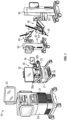
- a surgical robotic system 10 includes a control tower 20, which is connected to all of the components of the surgical robotic system 10 including a surgeon console 30 and one or more robotic arms 40.
- Each of the robotic arms 40 includes a surgical instrument 50 removably coupled thereto.
- Each of the robotic arms 40 is also coupled to a movable cart 60.
- One of the robotic arms 40 may include the endoscopic camera 51 configured to capture video of the surgical site.
- the endoscopic camera 51 may be a stereoscopic endoscope configured to capture two side-by-side (i.e., left and right) images of the surgical site to produce a video stream of the surgical scene.
- the endoscopic camera 51 is coupled to a video processing device 56, which may be disposed within the control tower 20.
- the video processing device 56 may be any computing device as described below configured to receive the video feed from the endoscopic camera 51 perform the image processing based on the depth estimating algorithms of the present disclosure and output the processed video stream.
- the surgeon console 30 includes a first display 32, which displays a video feed of the surgical site provided by camera 51 of the surgical instrument 50 disposed on the robotic arms 40, and a second display 34, which displays a user interface for controlling the surgical robotic system 10.
- the first and second displays 32 and 34 are touchscreens allowing for displaying various graphical user inputs.
- the video processing device 56 is configured to process the video feed from the endoscopic camera 51 and to output a processed video stream on the first displays 32 of the surgeon console 30 and/or the display 23 of the control tower 20.
- the surgeon console 30 also includes a plurality of user interface devices, such as foot pedals 36 and a pair of handle controllers 38a and 38b which are used by a user to remotely control robotic arms 40.
- the surgeon console further includes an armrest 33 used to support clinician's arms while operating the handle controllers 38a and 38b.
- the control tower 20 includes a display 23, which may be a touchscreen, and outputs on the graphical user interfaces (GUIs).
- GUIs graphical user interfaces
- the control tower 20 also acts as an interface between the surgeon console 30 and one or more robotic arms 40.
- the control tower 20 is configured to control the robotic arms 40, such as to move the robotic arms 40 and the corresponding surgical instrument 50, based on a set of programmable instructions and/or input commands from the surgeon console 30, in such a way that robotic arms 40 and the surgical instrument 50 execute a desired movement sequence in response to input from the foot pedals 36 and the handle controllers 38a and 38b.
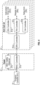
- Each of the control tower 20, the surgeon console 30, and the robotic arm 40 includes a respective computer 21, 31, 41.
- the computers 21, 31, 41 are interconnected to each other using any suitable communication network based on wired or wireless communication protocols.
- Suitable protocols include, but are not limited to, transmission control protocol/internet protocol (TCP/IP), datagram protocol/internet protocol (UDP/IP), and/or datagram congestion control protocol (DCCP).
- Wireless communication may be achieved via one or more wireless configurations, e.g., radio frequency, optical, Wi-Fi, Bluetooth (an open wireless protocol for exchanging data over short distances, using short length radio waves, from fixed and mobile devices, creating personal area networks (PANs), ZigBee ® (a specification for a suite of high level communication protocols using small, low-power digital radios based on the IEEE 122.15.4-2003 standard for wireless personal area networks (WPANs)).
- wireless configurations e.g., radio frequency, optical, Wi-Fi, Bluetooth (an open wireless protocol for exchanging data over short distances, using short length radio waves, from fixed and mobile devices, creating personal area networks (PANs), ZigBee ® (a specification for a suite of high level communication protocols using small, low-power digital radios based on the IEEE 122.15.4-2003 standard for wireless personal area networks (WPANs)).
- PANs personal area networks
- ZigBee ® a specification for a suite of high level communication protocols using small, low-power
- the computers 21, 31, 41 may include any suitable processor (not shown) operably connected to a memory (not shown), which may include one or more of volatile, non-volatile, magnetic, optical, or electrical media, such as read-only memory (ROM), random access memory (RAM), electrically-erasable programmable ROM (EEPROM), non-volatile RAM (NVRAM), or flash memory.
- the processor may be any suitable processor (e.g., control circuit) adapted to perform the operations, calculations, and/or set of instructions described in the present disclosure including, but not limited to, a hardware processor, a field programmable gate array (FPGA), a digital signal processor (DSP), a central processing unit (CPU), a microprocessor, and combinations thereof.
- FPGA field programmable gate array
- DSP digital signal processor
- CPU central processing unit
- microprocessor e.g., microprocessor
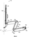
- each of the robotic arms 40 may include a plurality of links 42a, 42b, 42c, which are interconnected at joints 44a, 44b, 44c, respectively.
- the joint 44a is configured to secure the robotic arm 40 to the movable cart 60 and defines a first longitudinal axis.
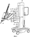
- the movable cart 60 includes a lift 61 and a setup arm 62, which provides a base for mounting of the robotic arm 40.
- the lift 61 allows for vertical movement of the setup arm 62.
- the movable cart 60 also includes a display 69 for displaying information pertaining to the robotic arm 40.
- the third link 62c includes a rotatable base 64 having two degrees of freedom.
- the rotatable base 64 includes a first actuator 64a and a second actuator 64b.
- the first actuator 64a is rotatable about a first stationary arm axis which is perpendicular to a plane defined by the third link 62c and the second actuator 64b is rotatable about a second stationary arm axis which is transverse to the first stationary arm axis.
- the first and second actuators 64a and 64b allow for full three-dimensional orientation of the robotic arm 40.
- the angles between the links 42a, 42b, 42c, and the holder 46 are also adjusted in order to achieve the desired angle ⁇ .
- some or all of the joints 44a, 44b, 44c may include an actuator to obviate the need for mechanical linkages.
- the robotic arm 40 also includes a holder 46 defining a second longitudinal axis and configured to receive an instrument drive unit (IDU) 52 ( FIG. 1 ).
- the IDU 52 is configured to couple to an actuation mechanism of the surgical instrument 50 and the camera 51 and is configured to move (e.g., rotate) and actuate the instrument 50 and/or the camera 51.
- IDU 52 transfers actuation forces from its actuators to the surgical instrument 50 to actuate components (e.g., end effector) of the surgical instrument 50.
- the holder 46 includes a sliding mechanism 46a, which is configured to move the IDU 52 along the second longitudinal axis defined by the holder 46.
- the holder 46 also includes a joint 46b, which rotates the holder 46 relative to the link 42c.
- the instrument 50 may be inserted through an endoscopic port 55 ( FIG. 3 ) held by the holder 46.
- the controller 21a also receives the actual joint angles measured by encoders of the actuators 48a and 48b and uses this information to determine force feedback commands that are transmitted back to the computer 31 of the surgeon console 30 to provide haptic feedback through the handle controllers 38a and 38b.
- the safety observer 21b performs validity checks on the data going into and out of the controller 21a and notifies a system fault handler if errors in the data transmission are detected to place the computer 21 and/or the surgical robotic system 10 into a safe state.
- the setup arm controller 41b controls each of joints 63a and 63b, and the rotatable base 64 of the setup arm 62 and calculates desired motor movement commands (e.g., motor torque) for the pitch axis and controls the brakes.
- the robotic arm controller 41c controls each joint 44a and 44b of the robotic arm 40 and calculates desired motor torques required for gravity compensation, friction compensation, and closed loop position control of the robotic arm 40.
- the robotic arm controller 41c calculates a movement command based on the calculated torque.
- the calculated motor commands are then communicated to one or more of the actuators 48a and 48b in the robotic arm 40.
- the actual joint positions are then transmitted by the actuators 48a and 48b back to the robotic arm controller 41c.
- the robotic arm 40 is controlled in response to a pose of the handle controller controlling the robotic arm 40, e.g., the handle controller 38a, which is transformed into a desired pose of the robotic arm 40 through a hand eye transform function executed by the controller 21a.
- the hand eye function as well as other functions described herein, is/are embodied in software executable by the controller 21a or any other suitable controller described herein.
- the pose of one of the handle controller 38a may be embodied as a coordinate position and role-pitch-yaw ("RPY") orientation relative to a coordinate reference frame, which is fixed to the surgeon console 30.
- the desired pose of the instrument 50 is relative to a fixed frame on the robotic arm 40.
- the desired pose of the robotic arm 40 is based on the pose of the handle controller 38a and is then passed by an inverse kinematics function executed by the controller 21a.
- the inverse kinematics function calculates angles for the joints 44a, 44b, 44c of the robotic arm 40 that achieve the scaled and adjusted pose input by the handle controller 38a.
- the calculated angles are then passed to the robotic arm controller 41c, which includes a joint axis controller having a proportional-derivative (PD) controller, the friction estimator module, the gravity compensator module, and a two-sided saturation block, which is configured to limit the commanded torque of the motors of the joints 44a, 44b, 44c.
- PD proportional-derivative
- the memory 106 may be any suitable storage device, such as flash memory and is configured to store identification information of the instrument 50, usage data, and the like.
- the memory 106 may be accessed by any controllers of the surgical robotic system 10, which may be the computers 21, 31, 41.
- the main controller 21a is configured to read and write to the memory 106 including retrieving and updating usage data.
- the computers 21, 31, 41 are configured to communicate with the memory 106 through the electrical connector 104 and/or any other wired or wireless interface.
- Usage data may be stored in any suitable data structure and includes actual time used, which may be measured in seconds, minutes, etc., number of uses.
- the main controller 21a uses the usage data to calculate remaining life of the instrument 50 and displays the remaining life on any of the displays 23, 32, and/or 34.
- any of the verifications i.e., expiration flag, time verification, use verification, predicted use verification
- the use prediction algorithm may be used for counting surgical instruments or other surgical appliances that are used with surgical systems, such as electrosurgical, ultrasonic, and powered surgical systems.
Landscapes
- Health & Medical Sciences (AREA)
- Engineering & Computer Science (AREA)
- Surgery (AREA)
- Life Sciences & Earth Sciences (AREA)
- Biomedical Technology (AREA)
- General Health & Medical Sciences (AREA)
- Medical Informatics (AREA)
- Public Health (AREA)
- Heart & Thoracic Surgery (AREA)
- Molecular Biology (AREA)
- Animal Behavior & Ethology (AREA)
- Nuclear Medicine, Radiotherapy & Molecular Imaging (AREA)
- Veterinary Medicine (AREA)
- Robotics (AREA)
- General Business, Economics & Management (AREA)
- Business, Economics & Management (AREA)
- Epidemiology (AREA)
- Primary Health Care (AREA)
- Human Computer Interaction (AREA)
- Oral & Maxillofacial Surgery (AREA)
- Pathology (AREA)
- Manipulator (AREA)
Claims (10)
- Chirurgisches Robotersystem (10), umfassend:einen Roboterarm (40);ein chirurgisches Instrument (50), das zur Kopplung mit dem Roboterarm (40) konfiguriert ist; undeine Steuerung (21a), die konfiguriert ist zum:Zugreifen auf Nutzungsdaten bezüglich des chirurgischen Instruments (50), wobei die Nutzungsdaten Daten zur maximalen Lebensdauer und Daten zur vorherigen Nutzung einschließen,dadurch gekennzeichnet, dass:die Daten zur maximalen Lebensdauer eine maximale Anzahl von Verwendungen und eine maximale Verwendungsdauer einschließen, und die Daten zur vorherigen Verwendung eine Anzahl vorheriger Verwendungen, eine vorherige Verwendungsdauer und eine Ablaufflagge einschließen; unddie Steuerung (21a) ferner konfiguriert ist zum:Berechnen einer durchschnittlichen Verwendungsdauer für das chirurgische Instrument (50) basierend auf der vorherigen Verwendungsdauer und der Anzahl vorheriger Verwendungen;Berechnen einer verbleibenden Verwendungsdauer für das chirurgische Instrument (50) basierend auf der vorherigen Verwendungsdauer und der maximalen Verwendungsdauer;Berechnen einer vorhergesagten Anzahl verbleibender Verwendungen für das chirurgische Instrument (50) basierend auf der verbleibenden Verwendungsdauer und der durchschnittlichen Verwendungsdauer; undDeaktivieren des chirurgischen Instruments (50), wenn die verbleibende Verwendungsdauer geringer als die durchschnittliche Verwendungsdauer ist.
- Chirurgisches Robotersystem nach Anspruch 1, wobei die Steuerung (21a) ferner konfiguriert ist, um das chirurgische Instrument (50) zu deaktivieren, basierend darauf, dass die Ablaufflagge auf "wahr" gesetzt ist.
- Chirurgisches Robotersystem nach Anspruch 1 oder 2, wobei die Steuerung (21a) ferner konfiguriert ist, um das chirurgische Instrument (50) zu deaktivieren, wenn die vorherige Verwendungsdauer die maximale Verwendungsdauer überschreitet.
- Chirurgisches Robotersystem nach einem der vorstehenden Ansprüche, wobei die Steuerung (21a) ferner konfiguriert ist, um das chirurgische Instrument (50) basierend auf der Anzahl vorheriger Verwendungen, die die maximale Anzahl von Verwendungen überschreitet, zu deaktivieren, und wobei das Deaktivieren das Verhindern der Betätigung des chirurgischen Instruments (50) als Reaktion auf eine Benutzereingabe einschließt.
- Chirurgisches Robotersystem nach einem der vorstehenden Ansprüche, ferner umfassend:
eine Anzeige (23, 32, 34, 200), die konfiguriert ist, um eine grafische Benutzerschnittstelle (150) auszugeben, die einen Nutzungsanzeigestatus in Bezug auf das chirurgische Instrument (50) einschließt. - Chirurgisches Robotersystem nach einem der vorstehenden Ansprüche, wobei das chirurgische Instrument (50) eine Speichervorrichtung (106) einschließt, die zum Speichern der Nutzungsdaten konfiguriert ist.
- Chirurgisches Robotersystem nach einem der vorstehenden Ansprüche, wobei die Steuerung (21a) ferner konfiguriert ist, um die Nutzungsdaten nach der Verwendung des chirurgischen Instruments (50) zu aktualisieren.
- Computerimplementiertes Verfahren zum Steuern eines chirurgischen Robotersystems (10) nach einem der vorstehenden Ansprüche, wobei das Verfahren umfasst:Zugreifen auf Nutzungsdaten bezüglich des chirurgischen Instruments, wobei die Nutzungsdaten Daten zur maximalen Lebensdauer und Daten zur vorherigen Nutzung einschließen;Berechnen der vorhergesagten Anzahl verbleibender Verwendungen für das chirurgische Instrument (50);wobei das Berechnen der vorhergesagten Anzahl verbleibender Verwendungen für das chirurgische Instrument die folgenden Schritte umfasst: Berechnen einer durchschnittlichen Verwendungsdauer für das chirurgische Instrument (50) basierend auf der vorherigen Verwendungsdauer und der Anzahl vorheriger Verwendungen; Berechnen einer verbleibenden Verwendungsdauer für das chirurgische Instrument (50) basierend auf der vorherigen Verwendungsdauer und der maximalen Verwendungsdauer; Berechnen einer vorhergesagten Anzahl verbleibender Verwendungen für das chirurgische Instrument (50) basierend auf der verbleibenden Verwendungsdauer und der durchschnittlichen Verwendungsdauer; undDeaktivieren des chirurgischen Instruments (50), wenn die vorhergesagte Anzahl verbleibender Verwendungen kleiner als 1 ist, wobei das Deaktivieren das Verhindern der Betätigung des chirurgischen Instruments als Reaktion auf eine Benutzereingabe einschließt.
- Verfahren nach Anspruch 8, ferner umfassend:
Anzeigen eines Nutzungsindikatorstatus bezüglich des chirurgischen Instruments auf einer grafischen Benutzerschnittstelle. - Verfahren nach Anspruch 8, ferner umfassend das Aktualisieren der Nutzungsdaten nach der Verwendung des chirurgischen Instruments.
Applications Claiming Priority (2)
| Application Number | Priority Date | Filing Date | Title |
|---|---|---|---|
| US202163228656P | 2021-08-03 | 2021-08-03 | |
| PCT/IB2022/056857 WO2023012574A1 (en) | 2021-08-03 | 2022-07-26 | System and method for surgical instrument use prediction |
Publications (2)
| Publication Number | Publication Date |
|---|---|
| EP4380489A1 EP4380489A1 (de) | 2024-06-12 |
| EP4380489B1 true EP4380489B1 (de) | 2025-04-16 |
Family
ID=82851880
Family Applications (1)
| Application Number | Title | Priority Date | Filing Date |
|---|---|---|---|
| EP22754172.9A Active EP4380489B1 (de) | 2021-08-03 | 2022-07-26 | System und verfahren zur vorhersage der verwendung eines chirurgischen instruments |
Country Status (3)
| Country | Link |
|---|---|
| US (1) | US20240315795A1 (de) |
| EP (1) | EP4380489B1 (de) |
| WO (1) | WO2023012574A1 (de) |
Families Citing this family (2)
| Publication number | Priority date | Publication date | Assignee | Title |
|---|---|---|---|---|
| CN121729744A (zh) * | 2023-08-22 | 2026-03-24 | 直观外科手术操作公司 | 线缆驱动式手术器械的年龄估计 |
| US20250072979A1 (en) * | 2023-08-28 | 2025-03-06 | Auris Health, Inc. | Predictive Maintenance for Robotically Assisted Surgical System |
Family Cites Families (7)
| Publication number | Priority date | Publication date | Assignee | Title |
|---|---|---|---|---|
| US7835823B2 (en) * | 2006-01-05 | 2010-11-16 | Intuitive Surgical Operations, Inc. | Method for tracking and reporting usage events to determine when preventive maintenance is due for a medical robotic system |
| WO2015142780A1 (en) * | 2014-03-17 | 2015-09-24 | Intuitive Surgical Operations, Inc. | Indicator mechanism for an actuator controlled surgical instrument |
| US9247996B1 (en) * | 2014-12-10 | 2016-02-02 | F21, Llc | System, method, and apparatus for refurbishment of robotic surgical arms |
| US9619618B2 (en) * | 2015-03-18 | 2017-04-11 | Covidien Lp | Systems and methods for credit-based usage of surgical instruments and components thereof |
| US10624667B2 (en) * | 2016-05-20 | 2020-04-21 | Ethicon Llc | System and method to track usage of surgical instrument |
| US12029512B2 (en) * | 2017-08-10 | 2024-07-09 | Intuitive Surgical Operations, Inc. | Increased usable instrument life in telesurgical systems |
| US11424027B2 (en) * | 2017-12-28 | 2022-08-23 | Cilag Gmbh International | Method for operating surgical instrument systems |
-
2022
- 2022-07-26 EP EP22754172.9A patent/EP4380489B1/de active Active
- 2022-07-26 US US18/576,145 patent/US20240315795A1/en active Pending
- 2022-07-26 WO PCT/IB2022/056857 patent/WO2023012574A1/en not_active Ceased
Also Published As
| Publication number | Publication date |
|---|---|
| EP4380489A1 (de) | 2024-06-12 |
| US20240315795A1 (en) | 2024-09-26 |
| WO2023012574A1 (en) | 2023-02-09 |
Similar Documents
| Publication | Publication Date | Title |
|---|---|---|
| EP4094711A1 (de) | Systeme und verfahren zur klinischen arbeitsraumsimulation | |
| EP4380489B1 (de) | System und verfahren zur vorhersage der verwendung eines chirurgischen instruments | |
| US20230210613A1 (en) | Surgical robotic system with motion integration | |
| US20250195166A1 (en) | Dynamic adjustment of system features, control, and data logging of surgical robotic systems | |
| WO2023114045A1 (en) | Surgical instrument for use in surgical robotic systems | |
| US20250143821A1 (en) | User-activated adaptive mode for surgical robotic system | |
| EP4316404A1 (de) | Chirurgisches robotersystem mit zugangsöffnungsspeicherung | |
| US20250082423A1 (en) | Semi-automatic positioning of multiple passive joints in a robotic system | |
| WO2024201216A1 (en) | Surgical robotic system and method for preventing instrument collision | |
| WO2023049489A1 (en) | System of operating surgical robotic systems with access ports of varying length | |
| US20240138940A1 (en) | Surgical robotic system and method for using instruments in training and surgical modes | |
| US20260026902A1 (en) | Robotic surgical system with multiple purpose surgical clip applier | |
| WO2024253981A1 (en) | Surgical robotic system and method for cable fatigue estimation of surgical instruments | |
| WO2026022702A1 (en) | Surgical robotic system for parameter error-guided motion scaling for hard stop prevention | |
| WO2023026144A1 (en) | System and method of operating surgical robotic systems with access ports | |
| WO2022155066A1 (en) | Distributed safety network | |
| WO2025120445A1 (en) | Surgical robotic system for control of suture-cutting needle-driver instrument | |
| WO2023079521A1 (en) | Linear transmission mechanism for actuating a prismatic joint of a surgical robot | |
| EP4498969A1 (de) | Bidirektionaler mechanischer werkstückschalter für ein chirurgisches robotersystem | |
| WO2025191425A1 (en) | Surgical robotic system for overstroke adjustment based on jaw position | |
| CN121240833A (zh) | 手术机器人系统以及用于手柄控制器中的基于速度的力反馈的方法 |
Legal Events
| Date | Code | Title | Description |
|---|---|---|---|
| STAA | Information on the status of an ep patent application or granted ep patent |
Free format text: STATUS: UNKNOWN |
|
| STAA | Information on the status of an ep patent application or granted ep patent |
Free format text: STATUS: THE INTERNATIONAL PUBLICATION HAS BEEN MADE |
|
| PUAI | Public reference made under article 153(3) epc to a published international application that has entered the european phase |
Free format text: ORIGINAL CODE: 0009012 |
|
| STAA | Information on the status of an ep patent application or granted ep patent |
Free format text: STATUS: REQUEST FOR EXAMINATION WAS MADE |
|
| 17P | Request for examination filed |
Effective date: 20240227 |
|
| AK | Designated contracting states |
Kind code of ref document: A1 Designated state(s): AL AT BE BG CH CY CZ DE DK EE ES FI FR GB GR HR HU IE IS IT LI LT LU LV MC MK MT NL NO PL PT RO RS SE SI SK SM TR |
|
| DAV | Request for validation of the european patent (deleted) | ||
| DAX | Request for extension of the european patent (deleted) | ||
| GRAP | Despatch of communication of intention to grant a patent |
Free format text: ORIGINAL CODE: EPIDOSNIGR1 |
|
| STAA | Information on the status of an ep patent application or granted ep patent |
Free format text: STATUS: GRANT OF PATENT IS INTENDED |
|
| INTG | Intention to grant announced |
Effective date: 20241118 |
|
| GRAS | Grant fee paid |
Free format text: ORIGINAL CODE: EPIDOSNIGR3 |
|
| GRAA | (expected) grant |
Free format text: ORIGINAL CODE: 0009210 |
|
| STAA | Information on the status of an ep patent application or granted ep patent |
Free format text: STATUS: THE PATENT HAS BEEN GRANTED |
|
| AK | Designated contracting states |
Kind code of ref document: B1 Designated state(s): AL AT BE BG CH CY CZ DE DK EE ES FI FR GB GR HR HU IE IS IT LI LT LU LV MC MK MT NL NO PL PT RO RS SE SI SK SM TR |
|
| REG | Reference to a national code |
Ref country code: GB Ref legal event code: FG4D |
|
| REG | Reference to a national code |
Ref country code: CH Ref legal event code: EP Ref country code: DE Ref legal event code: R096 Ref document number: 602022013302 Country of ref document: DE |
|
| REG | Reference to a national code |
Ref country code: IE Ref legal event code: FG4D |
|
| REG | Reference to a national code |
Ref country code: NL Ref legal event code: MP Effective date: 20250416 |
|
| PG25 | Lapsed in a contracting state [announced via postgrant information from national office to epo] |
Ref country code: NL Free format text: LAPSE BECAUSE OF FAILURE TO SUBMIT A TRANSLATION OF THE DESCRIPTION OR TO PAY THE FEE WITHIN THE PRESCRIBED TIME-LIMIT Effective date: 20250416 |
|
| REG | Reference to a national code |
Ref country code: AT Ref legal event code: MK05 Ref document number: 1785021 Country of ref document: AT Kind code of ref document: T Effective date: 20250416 |
|
| PG25 | Lapsed in a contracting state [announced via postgrant information from national office to epo] |
Ref country code: FI Free format text: LAPSE BECAUSE OF FAILURE TO SUBMIT A TRANSLATION OF THE DESCRIPTION OR TO PAY THE FEE WITHIN THE PRESCRIBED TIME-LIMIT Effective date: 20250416 Ref country code: PT Free format text: LAPSE BECAUSE OF FAILURE TO SUBMIT A TRANSLATION OF THE DESCRIPTION OR TO PAY THE FEE WITHIN THE PRESCRIBED TIME-LIMIT Effective date: 20250818 Ref country code: ES Free format text: LAPSE BECAUSE OF FAILURE TO SUBMIT A TRANSLATION OF THE DESCRIPTION OR TO PAY THE FEE WITHIN THE PRESCRIBED TIME-LIMIT Effective date: 20250416 |
|
| PGFP | Annual fee paid to national office [announced via postgrant information from national office to epo] |
Ref country code: DE Payment date: 20250620 Year of fee payment: 4 |
|
| REG | Reference to a national code |
Ref country code: LT Ref legal event code: MG9D |
|
| PG25 | Lapsed in a contracting state [announced via postgrant information from national office to epo] |
Ref country code: GR Free format text: LAPSE BECAUSE OF FAILURE TO SUBMIT A TRANSLATION OF THE DESCRIPTION OR TO PAY THE FEE WITHIN THE PRESCRIBED TIME-LIMIT Effective date: 20250717 Ref country code: NO Free format text: LAPSE BECAUSE OF FAILURE TO SUBMIT A TRANSLATION OF THE DESCRIPTION OR TO PAY THE FEE WITHIN THE PRESCRIBED TIME-LIMIT Effective date: 20250716 |
|
| PG25 | Lapsed in a contracting state [announced via postgrant information from national office to epo] |
Ref country code: PL Free format text: LAPSE BECAUSE OF FAILURE TO SUBMIT A TRANSLATION OF THE DESCRIPTION OR TO PAY THE FEE WITHIN THE PRESCRIBED TIME-LIMIT Effective date: 20250416 |
|
| PG25 | Lapsed in a contracting state [announced via postgrant information from national office to epo] |
Ref country code: BG Free format text: LAPSE BECAUSE OF FAILURE TO SUBMIT A TRANSLATION OF THE DESCRIPTION OR TO PAY THE FEE WITHIN THE PRESCRIBED TIME-LIMIT Effective date: 20250416 |
|
| PG25 | Lapsed in a contracting state [announced via postgrant information from national office to epo] |
Ref country code: HR Free format text: LAPSE BECAUSE OF FAILURE TO SUBMIT A TRANSLATION OF THE DESCRIPTION OR TO PAY THE FEE WITHIN THE PRESCRIBED TIME-LIMIT Effective date: 20250416 |
|
| PG25 | Lapsed in a contracting state [announced via postgrant information from national office to epo] |
Ref country code: AT Free format text: LAPSE BECAUSE OF FAILURE TO SUBMIT A TRANSLATION OF THE DESCRIPTION OR TO PAY THE FEE WITHIN THE PRESCRIBED TIME-LIMIT Effective date: 20250416 |
|
| PG25 | Lapsed in a contracting state [announced via postgrant information from national office to epo] |
Ref country code: RS Free format text: LAPSE BECAUSE OF FAILURE TO SUBMIT A TRANSLATION OF THE DESCRIPTION OR TO PAY THE FEE WITHIN THE PRESCRIBED TIME-LIMIT Effective date: 20250716 |
|
| PG25 | Lapsed in a contracting state [announced via postgrant information from national office to epo] |
Ref country code: IS Free format text: LAPSE BECAUSE OF FAILURE TO SUBMIT A TRANSLATION OF THE DESCRIPTION OR TO PAY THE FEE WITHIN THE PRESCRIBED TIME-LIMIT Effective date: 20250816 |
|
| PG25 | Lapsed in a contracting state [announced via postgrant information from national office to epo] |
Ref country code: LV Free format text: LAPSE BECAUSE OF FAILURE TO SUBMIT A TRANSLATION OF THE DESCRIPTION OR TO PAY THE FEE WITHIN THE PRESCRIBED TIME-LIMIT Effective date: 20250416 |
|
| PG25 | Lapsed in a contracting state [announced via postgrant information from national office to epo] |
Ref country code: DK Free format text: LAPSE BECAUSE OF FAILURE TO SUBMIT A TRANSLATION OF THE DESCRIPTION OR TO PAY THE FEE WITHIN THE PRESCRIBED TIME-LIMIT Effective date: 20250416 Ref country code: SM Free format text: LAPSE BECAUSE OF FAILURE TO SUBMIT A TRANSLATION OF THE DESCRIPTION OR TO PAY THE FEE WITHIN THE PRESCRIBED TIME-LIMIT Effective date: 20250416 |
|
| REG | Reference to a national code |
Ref country code: DE Ref legal event code: R097 Ref document number: 602022013302 Country of ref document: DE |
|
| PG25 | Lapsed in a contracting state [announced via postgrant information from national office to epo] |
Ref country code: CZ Free format text: LAPSE BECAUSE OF FAILURE TO SUBMIT A TRANSLATION OF THE DESCRIPTION OR TO PAY THE FEE WITHIN THE PRESCRIBED TIME-LIMIT Effective date: 20250416 |
|
| PG25 | Lapsed in a contracting state [announced via postgrant information from national office to epo] |
Ref country code: EE Free format text: LAPSE BECAUSE OF FAILURE TO SUBMIT A TRANSLATION OF THE DESCRIPTION OR TO PAY THE FEE WITHIN THE PRESCRIBED TIME-LIMIT Effective date: 20250416 |
|
| PG25 | Lapsed in a contracting state [announced via postgrant information from national office to epo] |
Ref country code: SK Free format text: LAPSE BECAUSE OF FAILURE TO SUBMIT A TRANSLATION OF THE DESCRIPTION OR TO PAY THE FEE WITHIN THE PRESCRIBED TIME-LIMIT Effective date: 20250416 |
|
| PG25 | Lapsed in a contracting state [announced via postgrant information from national office to epo] |
Ref country code: IT Free format text: LAPSE BECAUSE OF FAILURE TO SUBMIT A TRANSLATION OF THE DESCRIPTION OR TO PAY THE FEE WITHIN THE PRESCRIBED TIME-LIMIT Effective date: 20250416 |
|
| PLBE | No opposition filed within time limit |
Free format text: ORIGINAL CODE: 0009261 |
|
| STAA | Information on the status of an ep patent application or granted ep patent |
Free format text: STATUS: NO OPPOSITION FILED WITHIN TIME LIMIT |
|
| REG | Reference to a national code |
Ref country code: CH Ref legal event code: H13 Free format text: ST27 STATUS EVENT CODE: U-0-0-H10-H13 (AS PROVIDED BY THE NATIONAL OFFICE) Effective date: 20260224 |
|
| REG | Reference to a national code |
Ref country code: CH Ref legal event code: L10 Free format text: ST27 STATUS EVENT CODE: U-0-0-L10-L00 (AS PROVIDED BY THE NATIONAL OFFICE) Effective date: 20260225 |
|
| PG25 | Lapsed in a contracting state [announced via postgrant information from national office to epo] |
Ref country code: RO Free format text: LAPSE BECAUSE OF FAILURE TO SUBMIT A TRANSLATION OF THE DESCRIPTION OR TO PAY THE FEE WITHIN THE PRESCRIBED TIME-LIMIT Effective date: 20250416 |
|
| PG25 | Lapsed in a contracting state [announced via postgrant information from national office to epo] |
Ref country code: LU Free format text: LAPSE BECAUSE OF NON-PAYMENT OF DUE FEES Effective date: 20250726 |
|
| 26N | No opposition filed |
Effective date: 20260119 |