EP4380114A1 - Energy storage system - Google Patents
Energy storage system Download PDFInfo
- Publication number
- EP4380114A1 EP4380114A1 EP23743510.2A EP23743510A EP4380114A1 EP 4380114 A1 EP4380114 A1 EP 4380114A1 EP 23743510 A EP23743510 A EP 23743510A EP 4380114 A1 EP4380114 A1 EP 4380114A1
- Authority
- EP
- European Patent Office
- Prior art keywords
- communication line
- battery
- master controller
- energy storage
- container
- Prior art date
- Legal status (The legal status is an assumption and is not a legal conclusion. Google has not performed a legal analysis and makes no representation as to the accuracy of the status listed.)
- Granted
Links
Images


Classifications
-
- A—HUMAN NECESSITIES
- A62—LIFE-SAVING; FIRE-FIGHTING
- A62C—FIRE-FIGHTING
- A62C37/00—Control of fire-fighting equipment
- A62C37/04—Control of fire-fighting equipment with electrically-controlled release
-
- H—ELECTRICITY
- H01—ELECTRIC ELEMENTS
- H01M—PROCESSES OR MEANS, e.g. BATTERIES, FOR THE DIRECT CONVERSION OF CHEMICAL ENERGY INTO ELECTRICAL ENERGY
- H01M10/00—Secondary cells; Manufacture thereof
- H01M10/42—Methods or arrangements for servicing or maintenance of secondary cells or secondary half-cells
-
- A—HUMAN NECESSITIES
- A62—LIFE-SAVING; FIRE-FIGHTING
- A62C—FIRE-FIGHTING
- A62C3/00—Fire prevention, containment or extinguishing specially adapted for particular objects or places
- A62C3/16—Fire prevention, containment or extinguishing specially adapted for particular objects or places in electrical installations, e.g. cableways
-
- A—HUMAN NECESSITIES
- A62—LIFE-SAVING; FIRE-FIGHTING
- A62C—FIRE-FIGHTING
- A62C35/00—Permanently-installed equipment
- A62C35/02—Permanently-installed equipment with containers for delivering the extinguishing substance
- A62C35/026—Permanently-installed equipment with containers for delivering the extinguishing substance the extinguishing material being put under pressure by means other than pressure gas, e.g. pumps
-
- H—ELECTRICITY
- H01—ELECTRIC ELEMENTS
- H01M—PROCESSES OR MEANS, e.g. BATTERIES, FOR THE DIRECT CONVERSION OF CHEMICAL ENERGY INTO ELECTRICAL ENERGY
- H01M10/00—Secondary cells; Manufacture thereof
- H01M10/42—Methods or arrangements for servicing or maintenance of secondary cells or secondary half-cells
- H01M10/425—Structural combination with electronic components, e.g. electronic circuits integrated to the outside of the casing
-
- H—ELECTRICITY
- H01—ELECTRIC ELEMENTS
- H01M—PROCESSES OR MEANS, e.g. BATTERIES, FOR THE DIRECT CONVERSION OF CHEMICAL ENERGY INTO ELECTRICAL ENERGY
- H01M10/00—Secondary cells; Manufacture thereof
- H01M10/42—Methods or arrangements for servicing or maintenance of secondary cells or secondary half-cells
- H01M10/48—Accumulators combined with arrangements for measuring, testing or indicating the condition of cells, e.g. the level or density of the electrolyte
- H01M10/486—Accumulators combined with arrangements for measuring, testing or indicating the condition of cells, e.g. the level or density of the electrolyte for measuring temperature
-
- H—ELECTRICITY
- H04—ELECTRIC COMMUNICATION TECHNIQUE
- H04L—TRANSMISSION OF DIGITAL INFORMATION, e.g. TELEGRAPHIC COMMUNICATION
- H04L12/00—Data switching networks
- H04L12/28—Data switching networks characterised by path configuration, e.g. LAN [Local Area Networks] or WAN [Wide Area Networks]
- H04L12/40—Bus networks
-
- H—ELECTRICITY
- H04—ELECTRIC COMMUNICATION TECHNIQUE
- H04L—TRANSMISSION OF DIGITAL INFORMATION, e.g. TELEGRAPHIC COMMUNICATION
- H04L12/00—Data switching networks
- H04L12/28—Data switching networks characterised by path configuration, e.g. LAN [Local Area Networks] or WAN [Wide Area Networks]
- H04L12/46—Interconnection of networks
-
- H—ELECTRICITY
- H01—ELECTRIC ELEMENTS
- H01M—PROCESSES OR MEANS, e.g. BATTERIES, FOR THE DIRECT CONVERSION OF CHEMICAL ENERGY INTO ELECTRICAL ENERGY
- H01M10/00—Secondary cells; Manufacture thereof
- H01M10/42—Methods or arrangements for servicing or maintenance of secondary cells or secondary half-cells
- H01M10/425—Structural combination with electronic components, e.g. electronic circuits integrated to the outside of the casing
- H01M2010/4271—Battery management systems including electronic circuits, e.g. control of current or voltage to keep battery in healthy state, cell balancing
-
- H—ELECTRICITY
- H01—ELECTRIC ELEMENTS
- H01M—PROCESSES OR MEANS, e.g. BATTERIES, FOR THE DIRECT CONVERSION OF CHEMICAL ENERGY INTO ELECTRICAL ENERGY
- H01M10/00—Secondary cells; Manufacture thereof
- H01M10/42—Methods or arrangements for servicing or maintenance of secondary cells or secondary half-cells
- H01M10/425—Structural combination with electronic components, e.g. electronic circuits integrated to the outside of the casing
- H01M2010/4278—Systems for data transfer from batteries, e.g. transfer of battery parameters to a controller, data transferred between battery controller and main controller
-
- H—ELECTRICITY
- H04—ELECTRIC COMMUNICATION TECHNIQUE
- H04L—TRANSMISSION OF DIGITAL INFORMATION, e.g. TELEGRAPHIC COMMUNICATION
- H04L12/00—Data switching networks
- H04L12/28—Data switching networks characterised by path configuration, e.g. LAN [Local Area Networks] or WAN [Wide Area Networks]
- H04L12/40—Bus networks
- H04L2012/40208—Bus networks characterized by the use of a particular bus standard
- H04L2012/40215—Controller Area Network CAN
-
- H—ELECTRICITY
- H04—ELECTRIC COMMUNICATION TECHNIQUE
- H04L—TRANSMISSION OF DIGITAL INFORMATION, e.g. TELEGRAPHIC COMMUNICATION
- H04L12/00—Data switching networks
- H04L12/28—Data switching networks characterised by path configuration, e.g. LAN [Local Area Networks] or WAN [Wide Area Networks]
- H04L12/40—Bus networks
- H04L2012/40208—Bus networks characterized by the use of a particular bus standard
- H04L2012/40228—Modbus
-
- Y—GENERAL TAGGING OF NEW TECHNOLOGICAL DEVELOPMENTS; GENERAL TAGGING OF CROSS-SECTIONAL TECHNOLOGIES SPANNING OVER SEVERAL SECTIONS OF THE IPC; TECHNICAL SUBJECTS COVERED BY FORMER USPC CROSS-REFERENCE ART COLLECTIONS [XRACs] AND DIGESTS
- Y02—TECHNOLOGIES OR APPLICATIONS FOR MITIGATION OR ADAPTATION AGAINST CLIMATE CHANGE
- Y02E—REDUCTION OF GREENHOUSE GAS [GHG] EMISSIONS, RELATED TO ENERGY GENERATION, TRANSMISSION OR DISTRIBUTION
- Y02E60/00—Enabling technologies; Technologies with a potential or indirect contribution to GHG emissions mitigation
- Y02E60/10—Energy storage using batteries
Definitions
- the present disclosure relates to an energy storage system, and more particularly, to an energy storage system including a control container, a battery container, and a watering container.
- Batteries commercially available at present include nickel-cadmium batteries, nickel hydrogen batteries, nickel-zinc batteries, lithium batteries and the like.
- the lithium batteries are in the limelight since they have almost no memory effect compared to nickel-based batteries and also have very low self-discharging rate and high energy density.
- An energy storage system using such a battery may be a device that stores a large amount of power and provides the stored power to a plurality of load facilities.
- the energy storage system is used in the form of an industrial, building, or household energy management system, and is used as a regular power grid and/or an emergency power grid by providing the stored power to load facilities at each point of use.
- the conventional energy storage system is configured in container units, and one container includes a plurality of battery racks, a switchboard, and the like. That is, a container of a size that can contain all components of the energy storage system is required.
- each energy storage system is composed of an independent container, there is a problem that the container-unit energy storage systems must be controlled individually.
- the present disclosure is designed to solve the problems of the related art, and therefore the present disclosure is directed to providing an energy storage system including a control container, a battery container, and a watering container in which a communication line may be formed by connecting connection terminals provided in advance.
- an energy storage system comprising: a control container configured to include a battery system controller (BSC); a master controller configured to be connected to the BSC through a first communication line; and a bank battery management system (BBMS) configured to be connected to the BSC through a second communication line; and a battery container configured to include a slave controller configured to be connected to the master controller through the first communication line; and a rack battery management system (RBMS) connected to the BBMS through the second communication line and configured to monitor a state of a corresponding battery rack.
- BSC battery system controller
- BBMS bank battery management system
- RBMS rack battery management system
- the master controller may be configured to be connected to a plurality of slave controllers included in the plurality of battery containers through the first communication line.
- the master controller may be configured to be directly connected to each of the plurality of slave controllers in a home run manner through the first communication line.
- the BBMS may be configured to be connected to a plurality of RBMSs included in the plurality of battery containers through the second communication line.
- the BBMS may be configured to be serially connected to the plurality of RBMSs in a daisy chain manner through the second communication line.
- the BSC may be configured to be connected to an external power conversion system (PCS) through the first communication line.
- PCS power conversion system
- the energy storage system may further comprise a watering container connected to the master controller through a third communication line and configured to output a fire extinguishing fluid therein to the battery rack when a watering command is received from the master controller.
- the energy storage system may further comprise a second control container configured to include a second master controller configured to be connected to the BSC through the first communication line; and a second BBMS configured to be connected to the BSC through the second communication line.
- the energy storage system may further comprise a second battery container configured to include a second slave controller configured to be connected to the second master controller through the first communication line; and a second RBMS connected to the second BBMS through the second communication line and configured to monitor a state of a corresponding second battery rack.
- the energy storage system may further comprise a second watering container connected to the second master controller through a third communication line and configured to output a fire extinguishing fluid therein to the second battery rack when a watering command is received from the second master controller.
- the battery container can be easily expanded in the energy storage system.
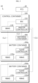
- FIG. 1 is a diagram schematically showing an energy storage system 10 according to an embodiment of the present disclosure.
- FIG. 2 is a diagram schematically showing the first embodiment of the energy storage system 10 according to an embodiment of the present disclosure.
- the energy storage system 10 may include a control container 100 and a battery container 200.
- the energy storage system 10 may be expressed as DC-LINK.
- the control container 100 may be expressed as E-LINK
- the battery container 200 may be expressed as B-LINK.
- the control container 100 may include a battery system controller (BSC) 110, a master controller 120, and a bank battery management system (BBMS) 130.
- BSC battery system controller
- BBMS bank battery management system
- the BSC 110 is a top-level controller and may be communicatively connected to the master controller 120 and the BBMS 130.
- the BSC 110 may be configured to be connected to an external power conversion system (PCS) 20 through a first communication line CL1.
- the first communication line CL1 may be a communication line applied to a first communication protocol.
- the first communication line CL1 may be a communication line for Modbus TCP/IP communication.
- the BSC 110 may be communicatively connected to the PCS 20 through the first communication line CL1.
- the master controller 120 may be configured to be connected to the BSC 110 through the first communication line CL1.
- the master controller 120 is a programmable logic controller (PLC) included in the E-LINK and may be expressed as E-PLC. That is, the master controller 120 may be connected to components such as a HVAC (Heating, Ventilation and Air Conditioning), an uninterruptible power supply system (UPS), a door sensor, a fuse, a switch, a switching mode power supply (SMPS), a fire suppression system (FSS), a surge protect device (SPD), an insulation monitoring device (IMD), and the like included in the control container 100 and control these components. Also, the master controller 120 may transmit control container information obtained from these components to the BSC 110 through the first communication line CL1. That is, the BSC 110 may receive the control container information obtained by the master controller 120 through the first communication line CL1. Also, the BSC 110 may control the master controller 120 to control each component included in the control container 100 based on the control container information.
- PLC programmable logic controller
- the master controller 120 may be communicatively connected to the BSC 110 through the first communication line CL1. That is, the PCS 20, the BSC 110, and the master controller 120 may be connected to each other through the first communication line CL1.
- the BBMS 130 may be configured to be connected to the BSC 110 through a second communication line CL2.
- the second communication line CL2 may be a communication line applied to a second communication protocol.
- the second communication line CL2 may be a communication line for controller area network (CAN) communication.
- CAN controller area network
- the BBMS 130 may be communicatively connected to the BSC 110 through the second communication line CL2. That is, the BSC 110 may be connected to the master controller 120 and the BBMS 130 through different communication lines. Therefore, even if a defect occurs in one communication line, the BSC 110 may continue communication through the remaining communication line.
- the battery container 200 may include a slave controller 210 and a rack battery management system (RBMS) 220. Unlike the control container 100, the battery container 200 may not include the BSC 110.
- RBMS rack battery management system
- the slave controller 210 may be configured to be connected to the master controller 120 through the first communication line CL1.
- the slave controller 210 is a PLC included in the B-LINK and may be expressed as B-PLC. That is, the slave controller 210 may be connected to a HVAC, an UPS, a door sensor, a gas sensor, a smoke sensor, a switch, a SMPS, a damper, a fan, a FSS, and the like included in the battery container 200 and control these components. Also, the slave controller 210 may transmit battery container information obtained from these components to the master controller 120 through the first communication line CL1. Also, the BSC 110 may receive the battery container information obtained by the master controller 120 through the first communication line CL1. That is, the BSC 110, the master controller 120, and the slave controller 210 may be connected to each other through the first communication line CL1. Also, the BSC 110 may control the slave controller 210 to control each component included in the battery container 200 based on the battery container information.
- the slave controller 210 may be communicatively connected to the master controller 120 through the first communication line CL1. That is, the BSC 110, the master controller 120, and the slave controller 210 may be connected to each other through the first communication line CL1.
- the RBMS 220 may be configured to be connected to the BBMS 130 through the second communication line CL2 and monitor the state of the corresponding battery rack.
- the battery container 200 may include at least one battery rack.
- each battery rack may include at least one battery module.
- the state of the battery module may be monitored by a module battery management system (MBMS).
- MBMS module battery management system
- at least one MBMS may be connected to the corresponding RBMS 220 through the second communication line CL2. That is, the RBMS 220 may monitor the state of the battery rack and the state of the battery module included in the battery rack.
- the RBMS 220 may be connected to the BBMS 130. That is, the BBMS 130 included in the control container 100 may be connected to the RBMS 220 included in the battery container 200 using the second communication line CL2. Also, the BBMS 130 may receive information of the corresponding battery rack from at least one RBMS 220 included in the battery container 200.
- the battery container 200 may include two RBMSs 220a, 220b.
- the RBMS 220a may be connected to the BBMS 130 through the second communication line CL2.
- the RBMS 220a may be connected to the RBMS 220b through the second communication line CL2. That is, the BSC 110 and the BBMS 130 included in the control container 100 may be communicatively connected to the RBMSs 220a, 220b included in the battery container 200 through the second communication line CL2.
- the energy storage system 10 may include a first communication line CL1 connecting the BSC 110, the master controller 120 and the slave controller 210, and a second communication line CL2 connecting the BSC 110, the BBMS 130 and the RBMS 220, respectively. Therefore, even if a defect occurs in any one communication line, communication can be continued through the other communication line.
- the energy storage system 10 has an advantage of establishing independent communication paths through different communication lines in consideration of communication targets and communication purposes. Therefore, stable communication can be performed in the energy storage system 10.
- FIG. 3 is a diagram schematically showing the second embodiment of the energy storage system 10 according to an embodiment of the present disclosure. Specifically, the embodiment of FIG. 3 is an embodiment in which a battery container 200b is further added to the embodiment of FIG. 2 .
- the master controller 120 may be configured to be connected to a plurality of slave controllers 210 included in the plurality of battery containers 200 through the first communication line CL1.
- the master controller 120 may be configured to be directly connected to each of the plurality of slave controllers 210 through the first communication line CL1.
- the master controller 120 may be configured to be directly connected to each of the plurality of slave controllers 210 through the first communication line CL1 in a home run manner.
- the master controller 120 may be directly connected to the slave controller 210a included in the battery container 200a through the first communication line CL1. Also, the master controller 120 may be directly connected to the slave controller 210b included in the battery container 200b through the first communication line CL1. That is, the communication structure between the master controller 120 and the slave controller 210a may not affect the communication structure between the master controller 120 and the slave controller 210b.
- the BBMS 130 may be configured to be connected to the plurality of RBMSs 220 included in the plurality of battery containers 200 through the second communication line CL2.
- the BBMS 130 may be configured to be serially connected to the plurality of RBMSs 220 through the second communication line CL2.
- the BBMS 130 may be serially connected to the plurality of RBMSs 220 through the second communication line CL2 in a daisy chain manner.
- the BBMS 130 may be connected to the RBMS 220a included in the battery container 200a through the second communication line CL2.
- the RBMS 220a may be connected to the RBMS 220b through the second communication line CL2.
- the RBMS 220b may be connected to the RBMS 220c included in the battery container 200b through the second communication line CL2.
- the RBMS 220c may be connected to the RBMS 220d through the second communication line CL2. That is, the BSC 110, the BBMS 130, the RBMS 220a, the RBMS 220b, the RBMS 220c, and the RBMS 220d may be connected through the second communication line CL2.
- the energy storage system 10 has an advantage of improving stability of each communication path by giving independence to the communication path along the first communication line CL1 and the communication path along the second communication line CL2.
- the energy storage system 10 may further include a watering container 300.
- the watering container 300 may include a water injection device capable of outputting a fire extinguishing fluid to the battery container 200 when a fire occurs in the battery container 200.
- the watering container 300 may be expressed as a water injection unit (WIU).
- WIU water injection unit
- the watering container 300 may be connected to the master controller 120 through a third communication line CL3, and may output a fire extinguishing fluid therein to a battery rack when a watering command is received from the master controller 120.
- the watering container 300 may include a control unit and a watering unit.
- the control unit may control the watering unit to output a fire extinguishing fluid.
- the watering unit may be connected to the RBMS 220 included in the battery container 200 through a pipeline.
- the watering unit may be connected to each battery module included in the RBMS 220 through a pipeline.
- a breakable bulb may be provided in the pipeline.
- the bulb may be configured to be damaged according to the temperature of the battery rack or battery module connected thereto.
- the control unit may receive a watering command.
- the control unit may control the watering unit so that the watering unit outputs a fire extinguishing fluid to the pipeline.
- the fire extinguishing fluid may be introduced into the battery module through the pipeline.
- the master controller 120 may be communicatively connected to the watering container 300 through the third communication line CL3.
- the third communication line CL3 may be a communication line applied to a third communication protocol.
- the third communication line CL3 may be a communication line for Modbus RTU communication.
- the energy storage system 10 has an advantage of securing communication stability for each communication path by establishing independent communication paths using each of the first communication line CL1, the second communication line CL2, and the third communication line CL3.
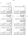
- FIG. 4 is a diagram schematically showing the third embodiment of the energy storage system 10 according to an embodiment of the present disclosure.
- the energy storage system 10 may include a plurality of control containers 100, 101, a plurality of battery containers 200a, 200b, 201a, 201b and a plurality of watering containers 300, 301.
- the energy storage system 10 according to the embodiment of FIG. 4 may further include a second control container 101, second battery containers 201a, 201b, and a second watering container 301 in the energy storage system 10 according to the embodiment of FIG. 3 .
- the second control container 101 may be configured to include a second master controller 121 and a second BBMS 131.
- the second master controller 121 may be configured to be connected to the BSC 110 through the first communication line CL1. That is, the BSC 110 included in the first control container 100 may not be included in the second control container 101.
- the BSC 110 may be included only in the first control container 100.
- the first master controller 120 and the second master controller 121 may be communicatively connected to the BSC 110 through the first communication line CL1. That is, even if a plurality of control containers 100, 101 are provided in the energy storage system 10, the BSC 110, which is a top-level controller, may be included in only one control container 100.
- the first master controller 120 may transmit information of the first control container obtained from components included in the first control container 100 to the BSC 110 through the first communication line CL1.
- the second master controller 121 may transmit information of the second control container obtained from components included in the second control container 101 to the BSC 110 through the first communication line CL1.
- the BSC 110 may control the first master controller 120 to control each component included in the first control container 100 based on the information of the first control container.
- the BSC 110 may control the second master controller 121 to control each component included in the second control container 101 based on the information of the second control container.
- the second BBMS 131 may be connected to the BSC 110 through the second communication line CL2.
- the second battery container 201 may include a second slave controller 211 and a second RBMS 221.
- the first control container 100 may be connected to the first battery containers 200a, 200b
- the second control container 101 may be connected to the second battery containers 201a, 201b.
- the second slave controller 211 may be configured to be connected to the second master controller 121 through the first communication line CL1.
- the second RBMS 221 may be configured to be connected to the second BBMS 131 through the second communication line CL2 and monitor the state of the corresponding second battery rack.
- the second watering container 301 may be configured to be connected to the second master controller 121 through the third communication line CL3, and output a fire extinguishing fluid therein to the second battery rack when a watering command is received from the second master controller 121.
- the communication structure between the master controller 121 and the slave controller 211, the communication structure between the BBMS 131 and the RBMS 221, and the communication structure between the master controller 121 and the watering container 301 may be the same as the communication structure described above.
- the second master controller 121 and the second slave controllers 211a, 211b may be connected through the first communication line CL1.
- the second BBMS 131 and the second RBMSs 221a, 221b, 221c, 221d may be connected through the second communication line CL2.
- the first master controller 120 and the first watering container 300 are connected through the third communication line CL3
- the second master controller 121 and the second watering container 301 may be connected through the third communication line CL3.
Landscapes
- Engineering & Computer Science (AREA)
- Health & Medical Sciences (AREA)
- Public Health (AREA)
- Business, Economics & Management (AREA)
- Emergency Management (AREA)
- Electrochemistry (AREA)
- Chemical & Material Sciences (AREA)
- Chemical Kinetics & Catalysis (AREA)
- Manufacturing & Machinery (AREA)
- General Chemical & Material Sciences (AREA)
- Computer Networks & Wireless Communication (AREA)
- Signal Processing (AREA)
- Microelectronics & Electronic Packaging (AREA)
- Supply And Distribution Of Alternating Current (AREA)
- Secondary Cells (AREA)
- Protection Of Static Devices (AREA)
- Charge And Discharge Circuits For Batteries Or The Like (AREA)
Abstract
Description
- The present application claims priority to
Korean Patent Application No. 10-2022-0008141 filed on January 19, 2022 Korean Patent Application No. 10-2023-0006968 filed on January 17, 2023 - The present disclosure relates to an energy storage system, and more particularly, to an energy storage system including a control container, a battery container, and a watering container.
- Recently, the demand for portable electronic products such as notebook computers, video cameras and portable telephones has increased sharply, and electric vehicles, energy storage batteries, robots, satellites and the like have been developed in earnest. Accordingly, high-performance batteries allowing repeated charging and discharging are being actively studied.
- Batteries commercially available at present include nickel-cadmium batteries, nickel hydrogen batteries, nickel-zinc batteries, lithium batteries and the like. Among them, the lithium batteries are in the limelight since they have almost no memory effect compared to nickel-based batteries and also have very low self-discharging rate and high energy density.
- An energy storage system using such a battery may be a device that stores a large amount of power and provides the stored power to a plurality of load facilities. For example, the energy storage system is used in the form of an industrial, building, or household energy management system, and is used as a regular power grid and/or an emergency power grid by providing the stored power to load facilities at each point of use.
- The conventional energy storage system is configured in container units, and one container includes a plurality of battery racks, a switchboard, and the like. That is, a container of a size that can contain all components of the energy storage system is required.
- In addition, when a plurality of energy storage systems are provided, since each energy storage system is composed of an independent container, there is a problem that the container-unit energy storage systems must be controlled individually.
- The present disclosure is designed to solve the problems of the related art, and therefore the present disclosure is directed to providing an energy storage system including a control container, a battery container, and a watering container in which a communication line may be formed by connecting connection terminals provided in advance.
- These and other objects and advantages of the present disclosure may be understood from the following detailed description and will become more fully apparent from the exemplary embodiments of the present disclosure. Also, it will be easily understood that the objects and advantages of the present disclosure may be realized by the means shown in the appended claims and combinations thereof.
- In one aspect of the present disclosure, there is provided an energy storage system, comprising: a control container configured to include a battery system controller (BSC); a master controller configured to be connected to the BSC through a first communication line; and a bank battery management system (BBMS) configured to be connected to the BSC through a second communication line; and a battery container configured to include a slave controller configured to be connected to the master controller through the first communication line; and a rack battery management system (RBMS) connected to the BBMS through the second communication line and configured to monitor a state of a corresponding battery rack.
- When the battery container are provided in plurality, the master controller may be configured to be connected to a plurality of slave controllers included in the plurality of battery containers through the first communication line.
- The master controller may be configured to be directly connected to each of the plurality of slave controllers in a home run manner through the first communication line.
- When the battery container is provided in plurality, the BBMS may be configured to be connected to a plurality of RBMSs included in the plurality of battery containers through the second communication line.
- The BBMS may be configured to be serially connected to the plurality of RBMSs in a daisy chain manner through the second communication line.
- The BSC may be configured to be connected to an external power conversion system (PCS) through the first communication line.
- The energy storage system according to another aspect of the present disclosure may further comprise a watering container connected to the master controller through a third communication line and configured to output a fire extinguishing fluid therein to the battery rack when a watering command is received from the master controller.
- The energy storage system according to another aspect of the present disclosure may further comprise a second control container configured to include a second master controller configured to be connected to the BSC through the first communication line; and a second BBMS configured to be connected to the BSC through the second communication line.
- The energy storage system according to another aspect of the present disclosure may further comprise a second battery container configured to include a second slave controller configured to be connected to the second master controller through the first communication line; and a second RBMS connected to the second BBMS through the second communication line and configured to monitor a state of a corresponding second battery rack.
- The energy storage system according to another aspect of the present disclosure may further comprise a second watering container connected to the second master controller through a third communication line and configured to output a fire extinguishing fluid therein to the second battery rack when a watering command is received from the second master controller.
- According to one aspect of the present disclosure, there is an advantage of improving communication stability of an energy storage system by connecting communication lines of the energy storage system using a home run manner and a daisy chain manner.
- In addition, according to one aspect of the present disclosure, there is an advantage in that the battery container can be easily expanded in the energy storage system.
- The effects of the present disclosure are not limited to the above, and other effects not mentioned herein will be clearly understood by those skilled in the art from the appended claims.
- The accompanying drawings illustrate a preferred embodiment of the present disclosure and together with the foregoing disclosure, serve to provide further understanding of the technical features of the present disclosure, and thus, the present disclosure is not construed as being limited to the drawing.
-
FIG. 1 is a diagram schematically showing an energy storage system according to an embodiment of the present disclosure. -
FIG. 2 is a diagram schematically showing the first embodiment of the energy storage system according to an embodiment of the present disclosure. -
FIG. 3 is a diagram schematically showing the second embodiment of the energy storage system according to an embodiment of the present disclosure. -
FIG. 4 is a diagram schematically showing the third embodiment of the energy storage system according to an embodiment of the present disclosure. - It should be understood that the terms used in the specification and the appended claims should not be construed as limited to general and dictionary meanings, but interpreted based on the meanings and concepts corresponding to technical aspects of the present disclosure on the basis of the principle that the inventor is allowed to define terms appropriately for the best explanation.
- Therefore, the description proposed herein is just a preferable example for the purpose of illustrations only, not intended to limit the scope of the disclosure, so it should be understood that other equivalents and modifications could be made thereto without departing from the scope of the disclosure.
- Additionally, in describing the present disclosure, when it is deemed that a detailed description of relevant known elements or functions renders the key subject matter of the present disclosure ambiguous, the detailed description is omitted herein.
- The terms including the ordinal number such as "first", "second" and the like, may be used to distinguish one element from another among various elements, but not intended to limit the elements by the terms.
- Throughout the specification, when a portion is referred to as "comprising" or "including" any element, it means that the portion may include other elements further, without excluding other elements, unless specifically stated otherwise.
- In addition, throughout the specification, when a portion is referred to as being "connected" to another portion, it is not limited to the case that they are "directly connected", but it also includes the case where they are "indirectly connected" with another element being interposed between them.
- Hereinafter, a preferred embodiment of the present disclosure will be described in detail with reference to the accompanying drawings.
-
FIG. 1 is a diagram schematically showing anenergy storage system 10 according to an embodiment of the present disclosure.FIG. 2 is a diagram schematically showing the first embodiment of theenergy storage system 10 according to an embodiment of the present disclosure. - Referring to
FIG. 1 , theenergy storage system 10 may include acontrol container 100 and abattery container 200. - For example, the
energy storage system 10 according to an embodiment of the present disclosure may be expressed as DC-LINK. Also, thecontrol container 100 may be expressed as E-LINK, and thebattery container 200 may be expressed as B-LINK. - The
control container 100 may include a battery system controller (BSC) 110, amaster controller 120, and a bank battery management system (BBMS) 130. - The BSC 110 is a top-level controller and may be communicatively connected to the
master controller 120 and the BBMS 130. - In addition, the
BSC 110 may be configured to be connected to an external power conversion system (PCS) 20 through a first communication line CL1. For example, the first communication line CL1 may be a communication line applied to a first communication protocol. As a specific example, the first communication line CL1 may be a communication line for Modbus TCP/IP communication. - For example, in the embodiment of
FIG. 2 , theBSC 110 may be communicatively connected to thePCS 20 through the first communication line CL1. - The
master controller 120 may be configured to be connected to theBSC 110 through the first communication line CL1. - Here, the
master controller 120 is a programmable logic controller (PLC) included in the E-LINK and may be expressed as E-PLC. That is, themaster controller 120 may be connected to components such as a HVAC (Heating, Ventilation and Air Conditioning), an uninterruptible power supply system (UPS), a door sensor, a fuse, a switch, a switching mode power supply (SMPS), a fire suppression system (FSS), a surge protect device (SPD), an insulation monitoring device (IMD), and the like included in thecontrol container 100 and control these components. Also, themaster controller 120 may transmit control container information obtained from these components to theBSC 110 through the first communication line CL1. That is, theBSC 110 may receive the control container information obtained by themaster controller 120 through the first communication line CL1. Also, theBSC 110 may control themaster controller 120 to control each component included in thecontrol container 100 based on the control container information. - For example, in the embodiment of
FIG. 2 , themaster controller 120 may be communicatively connected to theBSC 110 through the first communication line CL1. That is, the PCS 20, theBSC 110, and themaster controller 120 may be connected to each other through the first communication line CL1. - The
BBMS 130 may be configured to be connected to theBSC 110 through a second communication line CL2. For example, the second communication line CL2 may be a communication line applied to a second communication protocol. As a specific example, the second communication line CL2 may be a communication line for controller area network (CAN) communication. - For example, in the embodiment of
FIG. 2 , theBBMS 130 may be communicatively connected to theBSC 110 through the second communication line CL2. That is, theBSC 110 may be connected to themaster controller 120 and theBBMS 130 through different communication lines. Therefore, even if a defect occurs in one communication line, theBSC 110 may continue communication through the remaining communication line. - The
battery container 200 may include aslave controller 210 and a rack battery management system (RBMS) 220. Unlike thecontrol container 100, thebattery container 200 may not include theBSC 110. - The
slave controller 210 may be configured to be connected to themaster controller 120 through the first communication line CL1. - Here, the
slave controller 210 is a PLC included in the B-LINK and may be expressed as B-PLC. That is, theslave controller 210 may be connected to a HVAC, an UPS, a door sensor, a gas sensor, a smoke sensor, a switch, a SMPS, a damper, a fan, a FSS, and the like included in thebattery container 200 and control these components. Also, theslave controller 210 may transmit battery container information obtained from these components to themaster controller 120 through the first communication line CL1. Also, theBSC 110 may receive the battery container information obtained by themaster controller 120 through the first communication line CL1. That is, theBSC 110, themaster controller 120, and theslave controller 210 may be connected to each other through the first communication line CL1. Also, theBSC 110 may control theslave controller 210 to control each component included in thebattery container 200 based on the battery container information. - For example, in the embodiment of
FIG. 2 , theslave controller 210 may be communicatively connected to themaster controller 120 through the first communication line CL1. That is, theBSC 110, themaster controller 120, and theslave controller 210 may be connected to each other through the first communication line CL1. - The
RBMS 220 may be configured to be connected to theBBMS 130 through the second communication line CL2 and monitor the state of the corresponding battery rack. - Specifically, the
battery container 200 may include at least one battery rack. Also, each battery rack may include at least one battery module. The state of the battery module may be monitored by a module battery management system (MBMS). In addition, at least one MBMS may be connected to thecorresponding RBMS 220 through the second communication line CL2. That is, theRBMS 220 may monitor the state of the battery rack and the state of the battery module included in the battery rack. - Also, the
RBMS 220 may be connected to theBBMS 130. That is, theBBMS 130 included in thecontrol container 100 may be connected to theRBMS 220 included in thebattery container 200 using the second communication line CL2. Also, theBBMS 130 may receive information of the corresponding battery rack from at least oneRBMS 220 included in thebattery container 200. - For example, in the embodiment of
FIG. 2 , thebattery container 200 may include twoRBMSs RBMS 220a may be connected to theBBMS 130 through the second communication line CL2. Also, theRBMS 220a may be connected to theRBMS 220b through the second communication line CL2. That is, theBSC 110 and theBBMS 130 included in thecontrol container 100 may be communicatively connected to theRBMSs battery container 200 through the second communication line CL2. - The
energy storage system 10 according to an embodiment of the present disclosure may include a first communication line CL1 connecting theBSC 110, themaster controller 120 and theslave controller 210, and a second communication line CL2 connecting theBSC 110, theBBMS 130 and theRBMS 220, respectively. Therefore, even if a defect occurs in any one communication line, communication can be continued through the other communication line. - For example, even if communication between the
master controller 120 and theslave controller 210 is not normally performed since a problem occurs in the first communication line CL1, theBBMS 130 can normally receive battery rack information from theRBMS 220 through the second communication line CL2. Therefore, theenergy storage system 10 has an advantage of establishing independent communication paths through different communication lines in consideration of communication targets and communication purposes. Therefore, stable communication can be performed in theenergy storage system 10. -
FIG. 3 is a diagram schematically showing the second embodiment of theenergy storage system 10 according to an embodiment of the present disclosure. Specifically, the embodiment ofFIG. 3 is an embodiment in which abattery container 200b is further added to the embodiment ofFIG. 2 . - When the
battery container 200 is provided in plurality, themaster controller 120 may be configured to be connected to a plurality ofslave controllers 210 included in the plurality ofbattery containers 200 through the first communication line CL1. - Specifically, the
master controller 120 may be configured to be directly connected to each of the plurality ofslave controllers 210 through the first communication line CL1. For example, themaster controller 120 may be configured to be directly connected to each of the plurality ofslave controllers 210 through the first communication line CL1 in a home run manner. - For example, in the embodiment of
FIG. 3 , themaster controller 120 may be directly connected to theslave controller 210a included in thebattery container 200a through the first communication line CL1. Also, themaster controller 120 may be directly connected to theslave controller 210b included in thebattery container 200b through the first communication line CL1. That is, the communication structure between themaster controller 120 and theslave controller 210a may not affect the communication structure between themaster controller 120 and theslave controller 210b. - Also, when the
battery container 200 is provided in plurality, theBBMS 130 may be configured to be connected to the plurality ofRBMSs 220 included in the plurality ofbattery containers 200 through the second communication line CL2. - Specifically, the
BBMS 130 may be configured to be serially connected to the plurality ofRBMSs 220 through the second communication line CL2. TheBBMS 130 may be serially connected to the plurality ofRBMSs 220 through the second communication line CL2 in a daisy chain manner. - For example, in the embodiment of
FIG. 3 , theBBMS 130 may be connected to theRBMS 220a included in thebattery container 200a through the second communication line CL2. Also, theRBMS 220a may be connected to theRBMS 220b through the second communication line CL2. Also, theRBMS 220b may be connected to theRBMS 220c included in thebattery container 200b through the second communication line CL2. Also, theRBMS 220c may be connected to theRBMS 220d through the second communication line CL2. That is, theBSC 110, theBBMS 130, theRBMS 220a, theRBMS 220b, theRBMS 220c, and theRBMS 220d may be connected through the second communication line CL2. - The
energy storage system 10 according to an embodiment of the present disclosure has an advantage of improving stability of each communication path by giving independence to the communication path along the first communication line CL1 and the communication path along the second communication line CL2. - Referring to
FIG. 1 , theenergy storage system 10 may further include a wateringcontainer 300. - Specifically, the watering
container 300 may include a water injection device capable of outputting a fire extinguishing fluid to thebattery container 200 when a fire occurs in thebattery container 200. Also, the wateringcontainer 300 may be expressed as a water injection unit (WIU). - The watering
container 300 may be connected to themaster controller 120 through a third communication line CL3, and may output a fire extinguishing fluid therein to a battery rack when a watering command is received from themaster controller 120. - For example, the watering
container 300 may include a control unit and a watering unit. When receiving a watering command from themaster controller 120, the control unit may control the watering unit to output a fire extinguishing fluid. - In addition, the watering unit may be connected to the
RBMS 220 included in thebattery container 200 through a pipeline. Specifically, the watering unit may be connected to each battery module included in theRBMS 220 through a pipeline. Here, a breakable bulb may be provided in the pipeline. For example, the bulb may be configured to be damaged according to the temperature of the battery rack or battery module connected thereto. - For example, when a fire occurs in the
battery container 200, the control unit may receive a watering command. The control unit may control the watering unit so that the watering unit outputs a fire extinguishing fluid to the pipeline. In this case, since the bulb is broken in the pipeline corresponding to the battery module where the fire occurs, the fire extinguishing fluid may be introduced into the battery module through the pipeline. - In the embodiment of
FIG. 3 , themaster controller 120 may be communicatively connected to the wateringcontainer 300 through the third communication line CL3. For example, the third communication line CL3 may be a communication line applied to a third communication protocol. As a specific example, the third communication line CL3 may be a communication line for Modbus RTU communication. - The
energy storage system 10 according to an embodiment of the present disclosure has an advantage of securing communication stability for each communication path by establishing independent communication paths using each of the first communication line CL1, the second communication line CL2, and the third communication line CL3. -
FIG. 4 is a diagram schematically showing the third embodiment of theenergy storage system 10 according to an embodiment of the present disclosure. - Referring to
FIG. 4 , theenergy storage system 10 may include a plurality ofcontrol containers battery containers containers energy storage system 10 according to the embodiment ofFIG. 4 may further include asecond control container 101,second battery containers second watering container 301 in theenergy storage system 10 according to the embodiment ofFIG. 3 . - The
second control container 101 may be configured to include asecond master controller 121 and asecond BBMS 131. - Specifically, the
second master controller 121 may be configured to be connected to theBSC 110 through the first communication line CL1. That is, theBSC 110 included in thefirst control container 100 may not be included in thesecond control container 101. - For example, in the embodiment of
FIG. 4 , theBSC 110 may be included only in thefirst control container 100. Also, thefirst master controller 120 and thesecond master controller 121 may be communicatively connected to theBSC 110 through the first communication line CL1. That is, even if a plurality ofcontrol containers energy storage system 10, theBSC 110, which is a top-level controller, may be included in only onecontrol container 100. - For example, the
first master controller 120 may transmit information of the first control container obtained from components included in thefirst control container 100 to theBSC 110 through the first communication line CL1. Independently, thesecond master controller 121 may transmit information of the second control container obtained from components included in thesecond control container 101 to theBSC 110 through the first communication line CL1. TheBSC 110 may control thefirst master controller 120 to control each component included in thefirst control container 100 based on the information of the first control container. In addition, theBSC 110 may control thesecond master controller 121 to control each component included in thesecond control container 101 based on the information of the second control container. - The
second BBMS 131 may be configured to be connected to theBSC 110 through the second communication line CL2. - For example, in the embodiment of
FIG. 4 , thesecond BBMS 131 may be connected to theBSC 110 through the second communication line CL2. - The second battery container 201 may include a second slave controller 211 and a second RBMS 221. For example, in the embodiment of
FIG. 4 , thefirst control container 100 may be connected to thefirst battery containers second control container 101 may be connected to thesecond battery containers - The second slave controller 211 may be configured to be connected to the
second master controller 121 through the first communication line CL1. In addition, the second RBMS 221 may be configured to be connected to thesecond BBMS 131 through the second communication line CL2 and monitor the state of the corresponding second battery rack. - The
second watering container 301 may be configured to be connected to thesecond master controller 121 through the third communication line CL3, and output a fire extinguishing fluid therein to the second battery rack when a watering command is received from thesecond master controller 121. - Specifically, the communication structure between the
master controller 121 and the slave controller 211, the communication structure between theBBMS 131 and the RBMS 221, and the communication structure between themaster controller 121 and the wateringcontainer 301 may be the same as the communication structure described above. For example, in the embodiment ofFIG. 4 , in the same way that thefirst master controller 120 and thefirst slave controllers second master controller 121 and thesecond slave controllers first BBMS 130 and thefirst RBMSs second BBMS 131 and thesecond RBMSs first master controller 120 and thefirst watering container 300 are connected through the third communication line CL3, thesecond master controller 121 and thesecond watering container 301 may be connected through the third communication line CL3. - The
energy storage system 10 according to an embodiment of the present disclosure has a structural feature in which thecontrol containers battery containers 200, 201, and the wateringcontainers more battery containers 200, 201 can be connected to theenergy storage system 10, and theenergy storage system 10 can be overall monitored and controlled through oneBSC 110. That is, theenergy storage system 10 has an advantage of not only being scalable but also being capable of integrally controlled and managed through oneBSC 110. - The present disclosure has been described in detail. However, it should be understood that the detailed description and specific examples, while indicating preferred embodiments of the disclosure, are given by way of illustration only, since various changes and modifications within the scope of the disclosure will become apparent to those skilled in the art from this detailed description.
- In addition, since the present disclosure described above can be substituted, modified and changed in various ways by those skilled in the art without departing from the technical idea of the present disclosure, the present disclosure is not limited by the embodiments described above and the accompanying drawings, and all or some of the embodiments may be selectively combined to enable various modifications.
-
- 10: energy storage system
- 20: PCS
- 100: control container, first control container
- 101: second control container
- 110: BSC
- 120: master controller, first master controller
- 121: second master controller
- 130: BBMS, first BBMS
- 131: second BBMS
- 200: battery container
- 200a, 200b: battery container, first battery container
- 201a, 201b: second battery container
- 210: slave controller
- 210a, 210b: slave controller, first slave controller
- 211a, 211b: second slave controller
- 220a, 220b, 220c, 220d: RBMS, first RBMS
- 221a, 221b, 221c, 221d: second RBMS
- 300: watering container, first watering container
- 301: second watering container
Claims (10)
- An energy storage system, comprising:a control container configured to include a battery system controller (BSC); a master controller configured to be connected to the BSC through a first communication line; and a bank battery management system (BBMS) configured to be connected to the BSC through a second communication line; anda battery container configured to include a slave controller configured to be connected to the master controller through the first communication line; and a rack battery management system (RBMS) connected to the BBMS through the second communication line and configured to monitor a state of a corresponding battery rack.
- The energy storage system according to claim 1,
wherein when the battery container are provided in plurality, the master controller is configured to be connected to a plurality of slave controllers included in the plurality of battery containers through the first communication line. - The energy storage system according to claim 2,
wherein the master controller is configured to be directly connected to each of the plurality of slave controllers in a home run manner through the first communication line. - The energy storage system according to claim 1,
wherein when the battery container is provided in plurality, the BBMS is configured to be connected to a plurality of RBMSs included in the plurality of battery containers through the second communication line. - The energy storage system according to claim 4,
wherein the BBMS is configured to be serially connected to the plurality of RBMSs in a daisy chain manner through the second communication line. - The energy storage system according to claim 1,
wherein the BSC is configured to be connected to an external power conversion system (PCS) through the first communication line. - The energy storage system according to claim 1, further comprising a watering container connected to the master controller through a third communication line and configured to output a fire extinguishing fluid therein to the battery rack when a watering command is received from the master controller.
- The energy storage system according to claim 1, further comprising a second control container configured to include a second master controller configured to be connected to the BSC through the first communication line; and a second BBMS configured to be connected to the BSC through the second communication line.
- The energy storage system according to claim 8, further comprising a second battery container configured to include a second slave controller configured to be connected to the second master controller through the first communication line; and a second RBMS connected to the second BBMS through the second communication line and configured to monitor a state of a corresponding second battery rack.
- The energy storage system according to claim 9, further comprising a second watering container connected to the second master controller through a third communication line and configured to output a fire extinguishing fluid therein to the second battery rack when a watering command is received from the second master controller.
Priority Applications (1)
| Application Number | Priority Date | Filing Date | Title |
|---|---|---|---|
| EP26156221.9A EP4716162A2 (en) | 2022-01-19 | 2023-01-19 | Energy storage system |
Applications Claiming Priority (3)
| Application Number | Priority Date | Filing Date | Title |
|---|---|---|---|
| KR20220008141 | 2022-01-19 | ||
| KR1020230006968A KR102616748B1 (en) | 2022-01-19 | 2023-01-17 | Energy storage system |
| PCT/KR2023/000982 WO2023140666A1 (en) | 2022-01-19 | 2023-01-19 | Energy storage system |
Related Child Applications (2)
| Application Number | Title | Priority Date | Filing Date |
|---|---|---|---|
| EP26156221.9A Division EP4716162A2 (en) | 2022-01-19 | 2023-01-19 | Energy storage system |
| EP26156221.9A Division-Into EP4716162A2 (en) | 2022-01-19 | 2023-01-19 | Energy storage system |
Publications (3)
| Publication Number | Publication Date |
|---|---|
| EP4380114A1 true EP4380114A1 (en) | 2024-06-05 |
| EP4380114A4 EP4380114A4 (en) | 2025-01-22 |
| EP4380114B1 EP4380114B1 (en) | 2026-03-18 |
Family
ID=87348507
Family Applications (2)
| Application Number | Title | Priority Date | Filing Date |
|---|---|---|---|
| EP26156221.9A Pending EP4716162A2 (en) | 2022-01-19 | 2023-01-19 | Energy storage system |
| EP23743510.2A Active EP4380114B1 (en) | 2022-01-19 | 2023-01-19 | Energy storage system |
Family Applications Before (1)
| Application Number | Title | Priority Date | Filing Date |
|---|---|---|---|
| EP26156221.9A Pending EP4716162A2 (en) | 2022-01-19 | 2023-01-19 | Energy storage system |
Country Status (5)
| Country | Link |
|---|---|
| US (2) | US12337201B2 (en) |
| EP (2) | EP4716162A2 (en) |
| JP (1) | JP7678220B2 (en) |
| AU (1) | AU2023209310A1 (en) |
| WO (1) | WO2023140666A1 (en) |
Family Cites Families (20)
| Publication number | Priority date | Publication date | Assignee | Title |
|---|---|---|---|---|
| KR101406685B1 (en) * | 2012-12-12 | 2014-06-12 | 현대모비스 주식회사 | Distributrd battery management system and Method for distributrd battery management |
| CN103580089B (en) | 2012-07-25 | 2017-07-21 | 现代摩比斯株式会社 | distributed battery management system and distributed battery management method |
| KR102210890B1 (en) * | 2013-06-05 | 2021-02-02 | 삼성에스디아이 주식회사 | Battery management system, and method of managing the same |
| KR101741304B1 (en) * | 2014-11-10 | 2017-05-29 | 주식회사 엘지화학 | System and method for manage a battery cell using LC resonance |
| US20180056805A1 (en) * | 2016-08-27 | 2018-03-01 | Fang Shen | Method of Energizing Electric Vehicle Power Train with Multiple and Independently Controlled Battery Packs |
| KR101706717B1 (en) | 2016-11-04 | 2017-03-09 | 주식회사 아하정보통신 | Fire preventing device for battery pack of energy storage system |
| US20180337385A1 (en) * | 2017-05-17 | 2018-11-22 | Flex Ltd. | Direct current battery string aggregator for standard energy storage enclosure platform |
| KR102474424B1 (en) | 2017-10-31 | 2022-12-05 | 주식회사 엘엑스세미콘 | Communication method between master controller and slave controller, the slave controller for the same, and battery management system using the same |
| KR102773891B1 (en) * | 2019-02-21 | 2025-02-27 | 주식회사 엘지에너지솔루션 | ESS Stabilization Systems and Method |
| CN111628231A (en) | 2019-02-28 | 2020-09-04 | 宁德时代新能源科技股份有限公司 | Container type energy storage system and environment control method thereof |
| KR102045489B1 (en) * | 2019-05-09 | 2019-11-18 | 풍성에너지 (주) | Device for prevention of fires in energy storage system, and method thereof |
| KR102679115B1 (en) * | 2019-07-03 | 2024-06-28 | 주식회사 엘지에너지솔루션 | System and method for managing battery |
| CN112193122A (en) | 2019-07-08 | 2021-01-08 | 北京德意新能科技有限公司 | Chrysanthemum chain structure battery management system applied to energy storage system |
| KR102237845B1 (en) * | 2019-08-02 | 2021-04-08 | 현진이앤에스 주식회사 | Method of protecting batteries by multiple pathes in an energy storage system |
| AU2020397698A1 (en) * | 2019-12-05 | 2022-05-26 | Tyco Fire Products Lp | Fire suppression system for a battery enclosure |
| US11211669B2 (en) * | 2020-02-07 | 2021-12-28 | Baidu Usa Llc | Battery backup unit (BBU) shelf with a fire extinguishing system |
| KR102461637B1 (en) | 2020-02-19 | 2022-11-03 | 이지에스주식회사 | Automatic early fire extinguishing system and controlling method for ess |
| KR20220008141A (en) | 2020-07-13 | 2022-01-20 | 현대자동차주식회사 | Apparatus and method for setting state of charge of battery |
| KR102510424B1 (en) | 2021-07-05 | 2023-03-15 | 대원강업주식회사 | Armrest for vehicle seat |
| CN113611927A (en) | 2021-07-30 | 2021-11-05 | 蜂巢能源科技有限公司 | Energy storage battery cluster system and thermal management method |
-
2023
- 2023-01-19 EP EP26156221.9A patent/EP4716162A2/en active Pending
- 2023-01-19 EP EP23743510.2A patent/EP4380114B1/en active Active
- 2023-01-19 AU AU2023209310A patent/AU2023209310A1/en active Pending
- 2023-01-19 JP JP2024514708A patent/JP7678220B2/en active Active
- 2023-01-19 WO PCT/KR2023/000982 patent/WO2023140666A1/en not_active Ceased
-
2024
- 2024-05-16 US US18/666,289 patent/US12337201B2/en active Active
-
2025
- 2025-05-13 US US19/207,076 patent/US20250269216A1/en active Pending
Also Published As
| Publication number | Publication date |
|---|---|
| US20240304876A1 (en) | 2024-09-12 |
| WO2023140666A1 (en) | 2023-07-27 |
| US20250269216A1 (en) | 2025-08-28 |
| US12337201B2 (en) | 2025-06-24 |
| EP4716162A2 (en) | 2026-03-25 |
| EP4380114A4 (en) | 2025-01-22 |
| EP4380114B1 (en) | 2026-03-18 |
| JP7678220B2 (en) | 2025-05-15 |
| AU2023209310A1 (en) | 2024-04-11 |
| JP2024533283A (en) | 2024-09-12 |
Similar Documents
| Publication | Publication Date | Title |
|---|---|---|
| EP4386932A1 (en) | Energy storage system | |
| KR102479719B1 (en) | System and Method for Controlling Battery | |
| US10568232B2 (en) | Modular uninterruptible power supply apparatus and methods of operating same | |
| CN102655243B (en) | Battery system | |
| US9478981B2 (en) | Battery system having identifiers and energy storage system including the same | |
| EP2840643B1 (en) | Slave controller, communication method, communication system, energy storage system including the communication system | |
| JP6395849B2 (en) | Device and method for wiring a battery management system | |
| EP2610993A1 (en) | Power supply device | |
| US11228185B2 (en) | Modular-scalable decentralized high voltage battery system | |
| US20170117709A1 (en) | Electric multi-mode power converter module and power system | |
| US20150048779A1 (en) | Battery system, method of controlling battery system and energy storage system including the same | |
| EP4380114B1 (en) | Energy storage system | |
| KR102616748B1 (en) | Energy storage system | |
| CN117678201A (en) | energy storage system | |
| EP4475266A1 (en) | Energy storage system with enhanced safety | |
| JP7109294B2 (en) | Power supply system and power grid connection system | |
| CN120784993A (en) | Lithium battery power supply system based on multiple hot standby | |
| CN112688413A (en) | Power supply system applied to container data center and container data center | |
| CN112688412A (en) | Power supply system applied to container data center and container data center |
Legal Events
| Date | Code | Title | Description |
|---|---|---|---|
| STAA | Information on the status of an ep patent application or granted ep patent |
Free format text: STATUS: THE INTERNATIONAL PUBLICATION HAS BEEN MADE |
|
| PUAI | Public reference made under article 153(3) epc to a published international application that has entered the european phase |
Free format text: ORIGINAL CODE: 0009012 |
|
| STAA | Information on the status of an ep patent application or granted ep patent |
Free format text: STATUS: REQUEST FOR EXAMINATION WAS MADE |
|
| 17P | Request for examination filed |
Effective date: 20240229 |
|
| AK | Designated contracting states |
Kind code of ref document: A1 Designated state(s): AL AT BE BG CH CY CZ DE DK EE ES FI FR GB GR HR HU IE IS IT LI LT LU LV MC ME MK MT NL NO PL PT RO RS SE SI SK SM TR |
|
| A4 | Supplementary search report drawn up and despatched |
Effective date: 20250103 |
|
| RIC1 | Information provided on ipc code assigned before grant |
Ipc: H04L 12/46 20060101ALI20241219BHEP Ipc: H01M 10/42 20060101ALI20241219BHEP Ipc: H04L 12/40 20060101AFI20241219BHEP |
|
| DAV | Request for validation of the european patent (deleted) | ||
| DAX | Request for extension of the european patent (deleted) | ||
| GRAP | Despatch of communication of intention to grant a patent |
Free format text: ORIGINAL CODE: EPIDOSNIGR1 |
|
| STAA | Information on the status of an ep patent application or granted ep patent |
Free format text: STATUS: GRANT OF PATENT IS INTENDED |
|
| INTG | Intention to grant announced |
Effective date: 20251009 |
|
| P01 | Opt-out of the competence of the unified patent court (upc) registered |
Free format text: CASE NUMBER: UPC_APP_0012205_4380114/2025 Effective date: 20251105 |
|
| GRAS | Grant fee paid |
Free format text: ORIGINAL CODE: EPIDOSNIGR3 |
|
| GRAA | (expected) grant |
Free format text: ORIGINAL CODE: 0009210 |
|
| STAA | Information on the status of an ep patent application or granted ep patent |
Free format text: STATUS: THE PATENT HAS BEEN GRANTED |
|
| AK | Designated contracting states |
Kind code of ref document: B1 Designated state(s): AL AT BE BG CH CY CZ DE DK EE ES FI FR GB GR HR HU IE IS IT LI LT LU LV MC ME MK MT NL NO PL PT RO RS SE SI SK SM TR |
|
| REG | Reference to a national code |
Ref country code: CH Ref legal event code: F10 Free format text: ST27 STATUS EVENT CODE: U-0-0-F10-F00 (AS PROVIDED BY THE NATIONAL OFFICE) Effective date: 20260318 Ref country code: GB Ref legal event code: FG4D |
|
| REG | Reference to a national code |
Ref country code: IE Ref legal event code: FG4D |
|
| REG | Reference to a national code |
Ref country code: DE Ref legal event code: R096 Ref document number: 602023013807 Country of ref document: DE |