EP4380039A1 - Electric motor drive device, and electric motor drive method - Google Patents
Electric motor drive device, and electric motor drive method Download PDFInfo
- Publication number
- EP4380039A1 EP4380039A1 EP22847404.5A EP22847404A EP4380039A1 EP 4380039 A1 EP4380039 A1 EP 4380039A1 EP 22847404 A EP22847404 A EP 22847404A EP 4380039 A1 EP4380039 A1 EP 4380039A1
- Authority
- EP
- European Patent Office
- Prior art keywords
- electric motor
- torque command
- torque
- value
- command value
- Prior art date
- Legal status (The legal status is an assumption and is not a legal conclusion. Google has not performed a legal analysis and makes no representation as to the accuracy of the status listed.)
- Pending
Links
Images



Classifications
-
- H—ELECTRICITY
- H02—GENERATION; CONVERSION OR DISTRIBUTION OF ELECTRIC POWER
- H02P—CONTROL OR REGULATION OF ELECTRIC MOTORS, ELECTRIC GENERATORS OR DYNAMO-ELECTRIC CONVERTERS; CONTROLLING TRANSFORMERS, REACTORS OR CHOKE COILS
- H02P27/00—Arrangements or methods for the control of AC motors characterised by the kind of supply voltage
- H02P27/04—Arrangements or methods for the control of AC motors characterised by the kind of supply voltage using variable-frequency supply voltage, e.g. inverter or converter supply voltage
- H02P27/06—Arrangements or methods for the control of AC motors characterised by the kind of supply voltage using variable-frequency supply voltage, e.g. inverter or converter supply voltage using DC to AC converters or inverters
- H02P27/08—Arrangements or methods for the control of AC motors characterised by the kind of supply voltage using variable-frequency supply voltage, e.g. inverter or converter supply voltage using DC to AC converters or inverters with pulse width modulation
-
- B—PERFORMING OPERATIONS; TRANSPORTING
- B60—VEHICLES IN GENERAL
- B60L—PROPULSION OF ELECTRICALLY-PROPELLED VEHICLES; SUPPLYING ELECTRIC POWER FOR AUXILIARY EQUIPMENT OF ELECTRICALLY-PROPELLED VEHICLES; ELECTRODYNAMIC BRAKE SYSTEMS FOR VEHICLES IN GENERAL; MAGNETIC SUSPENSION OR LEVITATION FOR VEHICLES; MONITORING OPERATING VARIABLES OF ELECTRICALLY-PROPELLED VEHICLES; ELECTRIC SAFETY DEVICES FOR ELECTRICALLY-PROPELLED VEHICLES
- B60L15/00—Methods, circuits, or devices for controlling the traction-motor speed of electrically-propelled vehicles
- B60L15/007—Physical arrangements or structures of drive train converters specially adapted for the propulsion motors of electric vehicles
-
- B—PERFORMING OPERATIONS; TRANSPORTING
- B60—VEHICLES IN GENERAL
- B60L—PROPULSION OF ELECTRICALLY-PROPELLED VEHICLES; SUPPLYING ELECTRIC POWER FOR AUXILIARY EQUIPMENT OF ELECTRICALLY-PROPELLED VEHICLES; ELECTRODYNAMIC BRAKE SYSTEMS FOR VEHICLES IN GENERAL; MAGNETIC SUSPENSION OR LEVITATION FOR VEHICLES; MONITORING OPERATING VARIABLES OF ELECTRICALLY-PROPELLED VEHICLES; ELECTRIC SAFETY DEVICES FOR ELECTRICALLY-PROPELLED VEHICLES
- B60L15/00—Methods, circuits, or devices for controlling the traction-motor speed of electrically-propelled vehicles
- B60L15/02—Methods, circuits, or devices for controlling the traction-motor speed of electrically-propelled vehicles characterised by the form of the current used in the control circuit
-
- B—PERFORMING OPERATIONS; TRANSPORTING
- B60—VEHICLES IN GENERAL
- B60L—PROPULSION OF ELECTRICALLY-PROPELLED VEHICLES; SUPPLYING ELECTRIC POWER FOR AUXILIARY EQUIPMENT OF ELECTRICALLY-PROPELLED VEHICLES; ELECTRODYNAMIC BRAKE SYSTEMS FOR VEHICLES IN GENERAL; MAGNETIC SUSPENSION OR LEVITATION FOR VEHICLES; MONITORING OPERATING VARIABLES OF ELECTRICALLY-PROPELLED VEHICLES; ELECTRIC SAFETY DEVICES FOR ELECTRICALLY-PROPELLED VEHICLES
- B60L15/00—Methods, circuits, or devices for controlling the traction-motor speed of electrically-propelled vehicles
- B60L15/02—Methods, circuits, or devices for controlling the traction-motor speed of electrically-propelled vehicles characterised by the form of the current used in the control circuit
- B60L15/025—Methods, circuits, or devices for controlling the traction-motor speed of electrically-propelled vehicles characterised by the form of the current used in the control circuit using field orientation; Vector control; Direct Torque Control [DTC]
-
- B—PERFORMING OPERATIONS; TRANSPORTING
- B60—VEHICLES IN GENERAL
- B60L—PROPULSION OF ELECTRICALLY-PROPELLED VEHICLES; SUPPLYING ELECTRIC POWER FOR AUXILIARY EQUIPMENT OF ELECTRICALLY-PROPELLED VEHICLES; ELECTRODYNAMIC BRAKE SYSTEMS FOR VEHICLES IN GENERAL; MAGNETIC SUSPENSION OR LEVITATION FOR VEHICLES; MONITORING OPERATING VARIABLES OF ELECTRICALLY-PROPELLED VEHICLES; ELECTRIC SAFETY DEVICES FOR ELECTRICALLY-PROPELLED VEHICLES
- B60L15/00—Methods, circuits, or devices for controlling the traction-motor speed of electrically-propelled vehicles
- B60L15/20—Methods, circuits, or devices for controlling the traction-motor speed of electrically-propelled vehicles for control of the vehicle or its driving motor to achieve a desired performance, e.g. speed, torque, programmed variation of speed
- B60L15/2009—Methods, circuits, or devices for controlling the traction-motor speed of electrically-propelled vehicles for control of the vehicle or its driving motor to achieve a desired performance, e.g. speed, torque, programmed variation of speed for braking
-
- B—PERFORMING OPERATIONS; TRANSPORTING
- B60—VEHICLES IN GENERAL
- B60L—PROPULSION OF ELECTRICALLY-PROPELLED VEHICLES; SUPPLYING ELECTRIC POWER FOR AUXILIARY EQUIPMENT OF ELECTRICALLY-PROPELLED VEHICLES; ELECTRODYNAMIC BRAKE SYSTEMS FOR VEHICLES IN GENERAL; MAGNETIC SUSPENSION OR LEVITATION FOR VEHICLES; MONITORING OPERATING VARIABLES OF ELECTRICALLY-PROPELLED VEHICLES; ELECTRIC SAFETY DEVICES FOR ELECTRICALLY-PROPELLED VEHICLES
- B60L3/00—Electric devices on electrically-propelled vehicles for safety purposes; Monitoring operating variables, e.g. speed, deceleration or energy consumption
- B60L3/10—Indicating wheel slip ; Correction of wheel slip
- B60L3/102—Indicating wheel slip ; Correction of wheel slip of individual wheels
-
- B—PERFORMING OPERATIONS; TRANSPORTING
- B60—VEHICLES IN GENERAL
- B60L—PROPULSION OF ELECTRICALLY-PROPELLED VEHICLES; SUPPLYING ELECTRIC POWER FOR AUXILIARY EQUIPMENT OF ELECTRICALLY-PROPELLED VEHICLES; ELECTRODYNAMIC BRAKE SYSTEMS FOR VEHICLES IN GENERAL; MAGNETIC SUSPENSION OR LEVITATION FOR VEHICLES; MONITORING OPERATING VARIABLES OF ELECTRICALLY-PROPELLED VEHICLES; ELECTRIC SAFETY DEVICES FOR ELECTRICALLY-PROPELLED VEHICLES
- B60L3/00—Electric devices on electrically-propelled vehicles for safety purposes; Monitoring operating variables, e.g. speed, deceleration or energy consumption
- B60L3/10—Indicating wheel slip ; Correction of wheel slip
- B60L3/106—Indicating wheel slip ; Correction of wheel slip for maintaining or recovering the adhesion of the drive wheels
-
- B—PERFORMING OPERATIONS; TRANSPORTING
- B60—VEHICLES IN GENERAL
- B60L—PROPULSION OF ELECTRICALLY-PROPELLED VEHICLES; SUPPLYING ELECTRIC POWER FOR AUXILIARY EQUIPMENT OF ELECTRICALLY-PROPELLED VEHICLES; ELECTRODYNAMIC BRAKE SYSTEMS FOR VEHICLES IN GENERAL; MAGNETIC SUSPENSION OR LEVITATION FOR VEHICLES; MONITORING OPERATING VARIABLES OF ELECTRICALLY-PROPELLED VEHICLES; ELECTRIC SAFETY DEVICES FOR ELECTRICALLY-PROPELLED VEHICLES
- B60L9/00—Electric propulsion with power supply external to the vehicle
- B60L9/16—Electric propulsion with power supply external to the vehicle using AC induction motors
- B60L9/18—Electric propulsion with power supply external to the vehicle using AC induction motors fed from DC supply lines
-
- B—PERFORMING OPERATIONS; TRANSPORTING
- B60—VEHICLES IN GENERAL
- B60L—PROPULSION OF ELECTRICALLY-PROPELLED VEHICLES; SUPPLYING ELECTRIC POWER FOR AUXILIARY EQUIPMENT OF ELECTRICALLY-PROPELLED VEHICLES; ELECTRODYNAMIC BRAKE SYSTEMS FOR VEHICLES IN GENERAL; MAGNETIC SUSPENSION OR LEVITATION FOR VEHICLES; MONITORING OPERATING VARIABLES OF ELECTRICALLY-PROPELLED VEHICLES; ELECTRIC SAFETY DEVICES FOR ELECTRICALLY-PROPELLED VEHICLES
- B60L2200/00—Type of vehicles
- B60L2200/26—Rail vehicles
-
- B—PERFORMING OPERATIONS; TRANSPORTING
- B60—VEHICLES IN GENERAL
- B60L—PROPULSION OF ELECTRICALLY-PROPELLED VEHICLES; SUPPLYING ELECTRIC POWER FOR AUXILIARY EQUIPMENT OF ELECTRICALLY-PROPELLED VEHICLES; ELECTRODYNAMIC BRAKE SYSTEMS FOR VEHICLES IN GENERAL; MAGNETIC SUSPENSION OR LEVITATION FOR VEHICLES; MONITORING OPERATING VARIABLES OF ELECTRICALLY-PROPELLED VEHICLES; ELECTRIC SAFETY DEVICES FOR ELECTRICALLY-PROPELLED VEHICLES
- B60L2220/00—Electrical machine types; Structures or applications thereof
- B60L2220/40—Electrical machine applications
- B60L2220/42—Electrical machine applications with use of more than one motor
-
- B—PERFORMING OPERATIONS; TRANSPORTING
- B60—VEHICLES IN GENERAL
- B60L—PROPULSION OF ELECTRICALLY-PROPELLED VEHICLES; SUPPLYING ELECTRIC POWER FOR AUXILIARY EQUIPMENT OF ELECTRICALLY-PROPELLED VEHICLES; ELECTRODYNAMIC BRAKE SYSTEMS FOR VEHICLES IN GENERAL; MAGNETIC SUSPENSION OR LEVITATION FOR VEHICLES; MONITORING OPERATING VARIABLES OF ELECTRICALLY-PROPELLED VEHICLES; ELECTRIC SAFETY DEVICES FOR ELECTRICALLY-PROPELLED VEHICLES
- B60L2240/00—Control parameters of input or output; Target parameters
- B60L2240/10—Vehicle control parameters
- B60L2240/12—Speed
-
- B—PERFORMING OPERATIONS; TRANSPORTING
- B60—VEHICLES IN GENERAL
- B60L—PROPULSION OF ELECTRICALLY-PROPELLED VEHICLES; SUPPLYING ELECTRIC POWER FOR AUXILIARY EQUIPMENT OF ELECTRICALLY-PROPELLED VEHICLES; ELECTRODYNAMIC BRAKE SYSTEMS FOR VEHICLES IN GENERAL; MAGNETIC SUSPENSION OR LEVITATION FOR VEHICLES; MONITORING OPERATING VARIABLES OF ELECTRICALLY-PROPELLED VEHICLES; ELECTRIC SAFETY DEVICES FOR ELECTRICALLY-PROPELLED VEHICLES
- B60L2240/00—Control parameters of input or output; Target parameters
- B60L2240/40—Drive Train control parameters
- B60L2240/42—Drive Train control parameters related to electric machines
- B60L2240/421—Speed
-
- B—PERFORMING OPERATIONS; TRANSPORTING
- B60—VEHICLES IN GENERAL
- B60L—PROPULSION OF ELECTRICALLY-PROPELLED VEHICLES; SUPPLYING ELECTRIC POWER FOR AUXILIARY EQUIPMENT OF ELECTRICALLY-PROPELLED VEHICLES; ELECTRODYNAMIC BRAKE SYSTEMS FOR VEHICLES IN GENERAL; MAGNETIC SUSPENSION OR LEVITATION FOR VEHICLES; MONITORING OPERATING VARIABLES OF ELECTRICALLY-PROPELLED VEHICLES; ELECTRIC SAFETY DEVICES FOR ELECTRICALLY-PROPELLED VEHICLES
- B60L2240/00—Control parameters of input or output; Target parameters
- B60L2240/40—Drive Train control parameters
- B60L2240/42—Drive Train control parameters related to electric machines
- B60L2240/423—Torque
-
- B—PERFORMING OPERATIONS; TRANSPORTING
- B60—VEHICLES IN GENERAL
- B60L—PROPULSION OF ELECTRICALLY-PROPELLED VEHICLES; SUPPLYING ELECTRIC POWER FOR AUXILIARY EQUIPMENT OF ELECTRICALLY-PROPELLED VEHICLES; ELECTRODYNAMIC BRAKE SYSTEMS FOR VEHICLES IN GENERAL; MAGNETIC SUSPENSION OR LEVITATION FOR VEHICLES; MONITORING OPERATING VARIABLES OF ELECTRICALLY-PROPELLED VEHICLES; ELECTRIC SAFETY DEVICES FOR ELECTRICALLY-PROPELLED VEHICLES
- B60L2240/00—Control parameters of input or output; Target parameters
- B60L2240/40—Drive Train control parameters
- B60L2240/42—Drive Train control parameters related to electric machines
- B60L2240/429—Current
-
- B—PERFORMING OPERATIONS; TRANSPORTING
- B60—VEHICLES IN GENERAL
- B60L—PROPULSION OF ELECTRICALLY-PROPELLED VEHICLES; SUPPLYING ELECTRIC POWER FOR AUXILIARY EQUIPMENT OF ELECTRICALLY-PROPELLED VEHICLES; ELECTRODYNAMIC BRAKE SYSTEMS FOR VEHICLES IN GENERAL; MAGNETIC SUSPENSION OR LEVITATION FOR VEHICLES; MONITORING OPERATING VARIABLES OF ELECTRICALLY-PROPELLED VEHICLES; ELECTRIC SAFETY DEVICES FOR ELECTRICALLY-PROPELLED VEHICLES
- B60L2240/00—Control parameters of input or output; Target parameters
- B60L2240/40—Drive Train control parameters
- B60L2240/46—Drive Train control parameters related to wheels
- B60L2240/465—Slip
-
- B—PERFORMING OPERATIONS; TRANSPORTING
- B60—VEHICLES IN GENERAL
- B60L—PROPULSION OF ELECTRICALLY-PROPELLED VEHICLES; SUPPLYING ELECTRIC POWER FOR AUXILIARY EQUIPMENT OF ELECTRICALLY-PROPELLED VEHICLES; ELECTRODYNAMIC BRAKE SYSTEMS FOR VEHICLES IN GENERAL; MAGNETIC SUSPENSION OR LEVITATION FOR VEHICLES; MONITORING OPERATING VARIABLES OF ELECTRICALLY-PROPELLED VEHICLES; ELECTRIC SAFETY DEVICES FOR ELECTRICALLY-PROPELLED VEHICLES
- B60L2240/00—Control parameters of input or output; Target parameters
- B60L2240/40—Drive Train control parameters
- B60L2240/52—Drive Train control parameters related to converters
- B60L2240/526—Operating parameters
-
- B—PERFORMING OPERATIONS; TRANSPORTING
- B60—VEHICLES IN GENERAL
- B60L—PROPULSION OF ELECTRICALLY-PROPELLED VEHICLES; SUPPLYING ELECTRIC POWER FOR AUXILIARY EQUIPMENT OF ELECTRICALLY-PROPELLED VEHICLES; ELECTRODYNAMIC BRAKE SYSTEMS FOR VEHICLES IN GENERAL; MAGNETIC SUSPENSION OR LEVITATION FOR VEHICLES; MONITORING OPERATING VARIABLES OF ELECTRICALLY-PROPELLED VEHICLES; ELECTRIC SAFETY DEVICES FOR ELECTRICALLY-PROPELLED VEHICLES
- B60L2240/00—Control parameters of input or output; Target parameters
- B60L2240/40—Drive Train control parameters
- B60L2240/52—Drive Train control parameters related to converters
- B60L2240/529—Current
-
- B—PERFORMING OPERATIONS; TRANSPORTING
- B60—VEHICLES IN GENERAL
- B60L—PROPULSION OF ELECTRICALLY-PROPELLED VEHICLES; SUPPLYING ELECTRIC POWER FOR AUXILIARY EQUIPMENT OF ELECTRICALLY-PROPELLED VEHICLES; ELECTRODYNAMIC BRAKE SYSTEMS FOR VEHICLES IN GENERAL; MAGNETIC SUSPENSION OR LEVITATION FOR VEHICLES; MONITORING OPERATING VARIABLES OF ELECTRICALLY-PROPELLED VEHICLES; ELECTRIC SAFETY DEVICES FOR ELECTRICALLY-PROPELLED VEHICLES
- B60L2260/00—Operating Modes
- B60L2260/40—Control modes
- B60L2260/42—Control modes by adaptive correction
-
- B—PERFORMING OPERATIONS; TRANSPORTING
- B60—VEHICLES IN GENERAL
- B60L—PROPULSION OF ELECTRICALLY-PROPELLED VEHICLES; SUPPLYING ELECTRIC POWER FOR AUXILIARY EQUIPMENT OF ELECTRICALLY-PROPELLED VEHICLES; ELECTRODYNAMIC BRAKE SYSTEMS FOR VEHICLES IN GENERAL; MAGNETIC SUSPENSION OR LEVITATION FOR VEHICLES; MONITORING OPERATING VARIABLES OF ELECTRICALLY-PROPELLED VEHICLES; ELECTRIC SAFETY DEVICES FOR ELECTRICALLY-PROPELLED VEHICLES
- B60L2270/00—Problem solutions or means not otherwise provided for
- B60L2270/10—Emission reduction
- B60L2270/14—Emission reduction of noise
- B60L2270/145—Structure borne vibrations
-
- H—ELECTRICITY
- H02—GENERATION; CONVERSION OR DISTRIBUTION OF ELECTRIC POWER
- H02P—CONTROL OR REGULATION OF ELECTRIC MOTORS, ELECTRIC GENERATORS OR DYNAMO-ELECTRIC CONVERTERS; CONTROLLING TRANSFORMERS, REACTORS OR CHOKE COILS
- H02P29/00—Arrangements for regulating or controlling electric motors, appropriate for both AC and DC motors
- H02P29/02—Providing protection against overload without automatic interruption of supply
- H02P29/024—Detecting a fault condition, e.g. short circuit, locked rotor, open circuit or loss of load
- H02P29/028—Detecting a fault condition, e.g. short circuit, locked rotor, open circuit or loss of load the motor continuing operation despite the fault condition, e.g. eliminating, compensating for or remedying the fault
-
- Y—GENERAL TAGGING OF NEW TECHNOLOGICAL DEVELOPMENTS; GENERAL TAGGING OF CROSS-SECTIONAL TECHNOLOGIES SPANNING OVER SEVERAL SECTIONS OF THE IPC; TECHNICAL SUBJECTS COVERED BY FORMER USPC CROSS-REFERENCE ART COLLECTIONS [XRACs] AND DIGESTS
- Y02—TECHNOLOGIES OR APPLICATIONS FOR MITIGATION OR ADAPTATION AGAINST CLIMATE CHANGE
- Y02T—CLIMATE CHANGE MITIGATION TECHNOLOGIES RELATED TO TRANSPORTATION
- Y02T10/00—Road transport of goods or passengers
- Y02T10/60—Other road transportation technologies with climate change mitigation effect
- Y02T10/72—Electric energy management in electromobility
Definitions
- the present invention relates to a drive device and a drive method for driving an electric motor, and is particularly suitable as a drive device and a drive method for driving an electric motor mounted on a railway vehicle.
- a railway vehicle rotates wheels, which are drive wheels, by torque of a rotary electric machine, and accelerates the vehicle by a tangential force generated on the wheels as a reaction force that a wheel tread surface receives from a rail.
- This tangential force varies depending on the tangential force coefficient ⁇ representing the adhesion state between the wheels and the rails, and when the torque of the wheels becomes excessively larger than the tangential force, only the force for rotating the wheels increases while the force for accelerating the vehicle remains small. As a result, wheel slip or skidding of the wheels (hereinafter, also abbreviated as “wheel slip/skidding”) occurs. In particular, when it rains or it snows, the coefficient of adhesion greatly decreases, so that wheel slip/skidding is likely to occur.
- re-adhesion control is performed in which the torque generated by the electric motor is reduced to control to a re-adhesion state smaller than the tangential force (for example, PTLs 1, 2, and 3).
- PTLs 1, 2, and 3 describe techniques related to re-adhesion control, but the techniques described in PTLs 1 and 2 mainly aim at re-adhesion configuration such as improvement of adhesion utilization and setting of throttle torque, and do not mention the speed of torque reduction after wheel slip/skidding detection.
- An object of the present invention is to provide an electric motor drive device and an electric motor drive method capable of appropriately changing a torque reduced speed after wheel slip/skidding detection with a simple configuration.
- one of the representative electric motor drive devices of the present invention includes: an inverter that drives an electric motor; a current detecting circuit that detects a current of the electric motor; and a control device that controls the inverter based on a torque command value for the electric motor and a current detected value from the current detecting circuit, in which the control device changes a torque command reduced speed for the electric motor based on a wheel slip/skidding detection signal that has detected occurrence of wheel slip or skidding of the electric motor and the torque command value, and throttles torque of the electric motor.
- the torque command reduced speed is changed with reference to the torque command value, the torque command reduced speed is less susceptible to noise, and re-adhesion control can be performed with a simple configuration without using a first order lag filter or the like.
- re-adhesion control can be performed with a simple configuration without using a first order lag filter or the like.
- by appropriately reducing the torque it is possible to suppress rotational speed fluctuation at the time of wheel slip/skidding.
- the embodiment of the present invention will be described with reference to FIGs. 1 to 8 .
- the present embodiment is an example in which an electric motor mounted on a railway vehicle is driven by a drive device according to the present invention.
- FIG. 1 is a block diagram illustrating an overall configuration of an electric motor drive device according to the present embodiment.
- the drive device according to the present embodiment includes a control device 2, an inverter 3, and a current detecting circuit 4, and drives an electric motor 1.
- the control device 2 includes a vector control unit 21, a PWM pulse generating unit 22, a speed estimating unit 23, a torque command calculating unit 24, and a wheel slip/skidding detection determining unit 25, and performs drive control of the inverter 3.
- the vector control unit 21 calculates a voltage command value based on a torque command from the torque command calculating unit 24 and a current detected value from the current detecting circuit 4 that detects a current flowing through the electric motor 1.
- the PWM pulse generating unit 22 generates a PWM pulse signal on the basis of the voltage command value and supplies the PWM pulse signal to the inverter 3 as a drive signal.
- the inverter 3 generates an output voltage corresponding to the voltage command value and applies the output voltage to the electric motor 1.
- the vector control unit 21 can be realized by using general vector control, and the control method is not particularly specified.
- the wheel slip/skidding detection determining unit 25 receives rotation speed information of the electric motor 1 from the speed estimating unit 23, detects a wheel slip or skidding state, and outputs a wheel slip/skidding detection signal to the torque command calculating unit 24.
- the speed estimating unit 23 and the wheel slip/skidding detection determining unit 25 can be realized by a general speed estimation method and detection method, and the estimation method and detection method are not particularly specified.
- the torque command calculating unit 24 performs re-adhesion control including torque reduction when the wheel slip or skidding state is detected on the basis of the wheel slip/skidding detection signal.
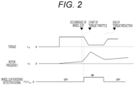
- FIG. 2 is a diagram illustrating an outline of operation waveforms at the time of general wheel slip detection and re-adhesion control when wheel slip occurs.
- the wheel slip/skidding detection determining unit 25 when deviation between the frequency conversion value of the vehicle speed and the rotor frequency exceeds a certain threshold, the wheel slip/skidding detection determining unit 25 outputs the wheel slip/skidding detection signal to the torque command calculating unit 24. Therefore, the wheel slip/skidding detection determining unit 25 may take in the vehicle speed from the outside as indicated by a dotted line in FIG. 1 .
- the torque command calculating unit 24 illustrated in FIG. 1 Upon receiving the wheel slip/skidding detection signal, the torque command calculating unit 24 illustrated in FIG. 1 performs the re-adhesion control including torque reduction (in a period from start of torque throttle to end of torque reduction illustrated in FIG. 2 ).
- the enlargement of the wheel slip state is suppressed, and the rotational speed fluctuation and the vibration to the vehicle are reduced.
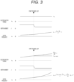
- FIG. 3 is a diagram illustrating a relationship between the electric motor torque and the rotor frequency when wheel slip occurs.
- FIG. 3 illustrates characteristics of a rotor frequency ⁇ r , electric motor torque ⁇ m , and inertia moment J of the electric motor 1.
- P m is the number of pole pairs of the electric motor 1
- the inertia moment J is treated as equivalent inertia moment obtained by synthesizing a mass of the vehicle and the adhesion due to a tangential force coefficient ⁇ in order to simplify the description.
- the inertia moment J is large in a state where the wheel and the rail adhere to each other, and in a case where wheel slip/skidding occurs between the wheel and the rail, it is regarded that the inertia moment J appears to be small.
- the characteristic illustrated on the upper side of FIG. 3 is a case where the electric motor torque ⁇ m is a fixed value. For example, a case of constant speed traveling without notching is applicable.
- the rotor frequency includes a primary component as expressed by the following formula (Formula 2), and increases at a constant inclination as illustrated in the upper side of FIG. 3 . In other words, the rotor frequency increases at a constant acceleration.
- ⁇ r ⁇ m ⁇ P m J ⁇ t
- the characteristic illustrated on the lower side of FIG. 3 is a case where the electric motor torque ⁇ m increases at a constant inclination.
- cases of acceleration due to notching, initial startup, and restart are applicable.
- the rotor frequency includes a primary component of fixed torque value ⁇ m-const at the start of wheel slip and a secondary component of torque gradient d ⁇ m /dt as expressed in the following formula (Formula 3), and increases secondarily as illustrated in the lower part of FIG. 3 .
- ⁇ r ⁇ m ⁇ const ⁇ P m J ⁇ t + d ⁇ m dt ⁇ P m ⁇ t 2
- the present invention proposes a configuration in which, when the electric motor torque command at the time of wheel slip/skidding detection is large or when the change in the electric motor torque command is large, it is determined that the rotor frequency quickly changes, and the torque command reduced speed is increased.
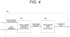
- FIG. 4 is a block diagram illustrating a configuration of a torque reduction calculating unit 26.
- the torque reduction calculating unit 26 is included in the torque command calculating unit 24 illustrated in FIG. 1 and includes a torque command change rate calculating unit 261 and a torque command reduced speed calculating unit 262.
- the torque command change rate calculating unit 261 determines a magnitude and inclination of the torque command value when the wheel slip or skidding is detected by the wheel slip/skidding detection signal, and calculates and outputs a torque command change rate.
- the torque command reduced speed calculating unit 262 calculates and outputs a torque command reduced speed based on the torque command change rate.
- the magnitude and the inclination of the torque command value can be easily obtained by referring to the value at the time of torque command generation.
- the torque command reduced speed calculating unit 262 can set the torque command reduced speed by using a table or a function that outputs the torque command reduced speed with at least one of the magnitude and the inclination of the torque command value as a reference value.
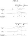
- FIG. 5 is a diagram illustrating an outline of operation waveforms at the time of the wheel slip detection and the re-adhesion control when the torque reduction calculating unit 26 is applied in a case in which the electric motor torque is a fixed value (upper side in FIG. 5 ) and a case in which the electric motor torque increases (lower side in FIG. 5 ). If the torque is not throttled the rotor frequency fluctuates as indicated by a dotted line in FIG. 5 .
- a predetermined upper limit value may be provided for the torque command reduced speed.
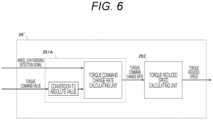
- FIG. 6 is a block diagram illustrating a configuration of a torque reduction calculating unit 26' in consideration of the skidding state.
- the torque reduction calculating unit 26' is also included in the torque command calculating unit 24 illustrated in FIG. 1 , and includes a torque command change rate calculating unit 261A and the torque command reduced speed calculating unit 262.
- the torque command change rate calculating unit 261A illustrated in FIG. 6 has a different configuration from that of the torque command change rate calculating unit 261 illustrated in FIG. 4 in that a torque command value that is input is converted into an absolute value in order to use the same logical configuration in both of the wheel slip and the skidding.
- a torque command value that is input is converted into an absolute value in order to use the same logical configuration in both of the wheel slip and the skidding.
- FIG. 7 is a diagram illustrating an outline of operation waveforms at the time of the skidding detection and the re-adhesion control when the torque reduction calculating unit 26' is applied in a case in which the electric motor torque increases in the negative direction.
- the torque command value obtained by converting the electric motor torque into an absolute value and indicated by a one-dot broken line is used to calculate the inclination of the torque command at the time of skidding detection (torque command change rate), and the torque command reduced speed calculating unit 262 outputs a torque command reduced speed d ⁇ m3 /dt.
- the calculation of the torque command reduced speed in the wheel slip or the skidding can be constructed with a simple configuration.
- FIG. 8 is a diagram illustrating a schematic configuration in a case where the electric motor drive device according to the present embodiment is applied to an electric motor for a railway vehicle.
- a railway vehicle 100 having an electric motor drive device receives supply of DC power from an overhead line 101, and travels along a rail 102 by wheels driven by the electric motor (for example, induction motors 1a to 1d).
- the electric motor drive device By applying the electric motor drive device according to the present embodiment, it is possible to suppress the rotational speed fluctuation of the electric motor for the railway vehicle at the time of occurrence of the wheel slip or the skidding, and to perform smooth re-adhesion control.
Landscapes
- Engineering & Computer Science (AREA)
- Power Engineering (AREA)
- Transportation (AREA)
- Mechanical Engineering (AREA)
- Life Sciences & Earth Sciences (AREA)
- Sustainable Development (AREA)
- Sustainable Energy (AREA)
- Electric Propulsion And Braking For Vehicles (AREA)
- Control Of Electric Motors In General (AREA)
Abstract
Description
- The present invention relates to a drive device and a drive method for driving an electric motor, and is particularly suitable as a drive device and a drive method for driving an electric motor mounted on a railway vehicle.
- A railway vehicle rotates wheels, which are drive wheels, by torque of a rotary electric machine, and accelerates the vehicle by a tangential force generated on the wheels as a reaction force that a wheel tread surface receives from a rail.
- This tangential force varies depending on the tangential force coefficient µ representing the adhesion state between the wheels and the rails, and when the torque of the wheels becomes excessively larger than the tangential force, only the force for rotating the wheels increases while the force for accelerating the vehicle remains small. As a result, wheel slip or skidding of the wheels (hereinafter, also abbreviated as "wheel slip/skidding") occurs. In particular, when it rains or it snows, the coefficient of adhesion greatly decreases, so that wheel slip/skidding is likely to occur.
- When such wheel slip/skidding occurs, re-adhesion control is performed in which the torque generated by the electric motor is reduced to control to a re-adhesion state smaller than the tangential force (for example,
PTLs 1, 2, and 3). -
- PTL 1:
JP 2000-358302 A - PTL 2:
JP 2013-188009 A - PTL 3:
JP 2019-201459 A -
PTLs PTLs 1 and 2 mainly aim at re-adhesion configuration such as improvement of adhesion utilization and setting of throttle torque, and do not mention the speed of torque reduction after wheel slip/skidding detection. - In addition, in the method described in
PTL 3, a configuration in which the speed of torque reduction after the wheel slip/skidding detection is reduced with reference to the acceleration of the wheels is described, but the torque reduced speed is easily affected by noise of the rotation speed, and the use of a first order lag filter or the like causes a problem that the structure becomes complicated. - An object of the present invention is to provide an electric motor drive device and an electric motor drive method capable of appropriately changing a torque reduced speed after wheel slip/skidding detection with a simple configuration.
- In order to solve the above problems, one of the representative electric motor drive devices of the present invention includes: an inverter that drives an electric motor; a current detecting circuit that detects a current of the electric motor; and a control device that controls the inverter based on a torque command value for the electric motor and a current detected value from the current detecting circuit, in which the control device changes a torque command reduced speed for the electric motor based on a wheel slip/skidding detection signal that has detected occurrence of wheel slip or skidding of the electric motor and the torque command value, and throttles torque of the electric motor.
- According to the present invention, since the torque command reduced speed is changed with reference to the torque command value, the torque command reduced speed is less susceptible to noise, and re-adhesion control can be performed with a simple configuration without using a first order lag filter or the like. In addition, by appropriately reducing the torque, it is possible to suppress rotational speed fluctuation at the time of wheel slip/skidding.
- Problems, configurations, and effects other than those described above will become apparent by the following description of an embodiment.
-
- [
FIG. 1] FIG. 1 is a block diagram illustrating an overall configuration of an electric motor drive device according to the present embodiment. - [
FIG. 2] FIG. 2 is a diagram illustrating an outline of operation waveforms at the time of general wheel slip detection and re-adhesion control when wheel slip occurs. - [
FIG. 3] FIG. 3 is a diagram illustrating a relationship between electric motor torque and a rotor frequency when wheel slip occurs. - [
FIG. 4] FIG. 4 is a block diagram illustrating a configuration of a torque reduction calculating unit. - [
FIG. 5] FIG. 5 is a diagram illustrating an outline of operation waveforms at the time of wheel slip detection and re-adhesion control when the torque reduction calculating unit is applied in a case in which the electric motor torque is a fixed value and a case in which the motor torque increases. - [
FIG. 6] FIG. 6 is a block diagram illustrating a configuration of a torque reduction calculating unit in consideration of a skidding state. - [
FIG. 7] FIG. 7 is a diagram illustrating an outline of operation waveforms at the time of skidding detection and re-adhesion control when the torque reduction calculating unit is applied in consideration of a skidding state in a case in which the electric motor torque increases in the negative direction. - [
FIG. 8] FIG. 8 is a diagram illustrating a schematic configuration in a case where the electric motor drive device according to the present embodiment is applied to an electric motor for a railway vehicle. - Hereinafter, an embodiment of the present invention will be described with reference to the drawings as a mode for carrying out the present invention. Note that the present invention is not limited by the embodiment. In the drawings, the same portions are denoted by the same reference numerals.
- The embodiment of the present invention will be described with reference to
FIGs. 1 to 8 . The present embodiment is an example in which an electric motor mounted on a railway vehicle is driven by a drive device according to the present invention. -
FIG. 1 is a block diagram illustrating an overall configuration of an electric motor drive device according to the present embodiment. As illustrated, the drive device according to the present embodiment includes acontrol device 2, aninverter 3, and a current detectingcircuit 4, and drives an electric motor 1. - The
control device 2 includes avector control unit 21, a PWMpulse generating unit 22, aspeed estimating unit 23, a torquecommand calculating unit 24, and a wheel slip/skiddingdetection determining unit 25, and performs drive control of theinverter 3. - In the
control device 2, thevector control unit 21 calculates a voltage command value based on a torque command from the torquecommand calculating unit 24 and a current detected value from the current detectingcircuit 4 that detects a current flowing through the electric motor 1. The PWMpulse generating unit 22 generates a PWM pulse signal on the basis of the voltage command value and supplies the PWM pulse signal to theinverter 3 as a drive signal. Theinverter 3 generates an output voltage corresponding to the voltage command value and applies the output voltage to the electric motor 1. Here, thevector control unit 21 can be realized by using general vector control, and the control method is not particularly specified. - The wheel slip/skidding
detection determining unit 25 receives rotation speed information of the electric motor 1 from thespeed estimating unit 23, detects a wheel slip or skidding state, and outputs a wheel slip/skidding detection signal to the torquecommand calculating unit 24. - Here, the
speed estimating unit 23 and the wheel slip/skiddingdetection determining unit 25 can be realized by a general speed estimation method and detection method, and the estimation method and detection method are not particularly specified. - In addition, the torque
command calculating unit 24 performs re-adhesion control including torque reduction when the wheel slip or skidding state is detected on the basis of the wheel slip/skidding detection signal. -
FIG. 2 is a diagram illustrating an outline of operation waveforms at the time of general wheel slip detection and re-adhesion control when wheel slip occurs. - In a case where the electric motor outputs torque and a rotor frequency increase, the wheel slip state in which the rotor frequency increases occurs when an adhesion coefficient decreases.
- For example, when deviation between the frequency conversion value of the vehicle speed and the rotor frequency exceeds a certain threshold, the wheel slip/skidding
detection determining unit 25 outputs the wheel slip/skidding detection signal to the torquecommand calculating unit 24. Therefore, the wheel slip/skiddingdetection determining unit 25 may take in the vehicle speed from the outside as indicated by a dotted line inFIG. 1 . - Upon receiving the wheel slip/skidding detection signal, the torque
command calculating unit 24 illustrated inFIG. 1 performs the re-adhesion control including torque reduction (in a period from start of torque throttle to end of torque reduction illustrated inFIG. 2 ). - According to the above operation mode, the enlargement of the wheel slip state is suppressed, and the rotational speed fluctuation and the vibration to the vehicle are reduced.
-
FIG. 3 is a diagram illustrating a relationship between the electric motor torque and the rotor frequency when wheel slip occurs.FIG. 3 illustrates characteristics of a rotor frequency ωr, electric motor torque τm, and inertia moment J of the electric motor 1. - Here, Pm is the number of pole pairs of the electric motor 1, and the inertia moment J is treated as equivalent inertia moment obtained by synthesizing a mass of the vehicle and the adhesion due to a tangential force coefficient µ in order to simplify the description.
- In addition, the inertia moment J is large in a state where the wheel and the rail adhere to each other, and in a case where wheel slip/skidding occurs between the wheel and the rail, it is regarded that the inertia moment J appears to be small.
- The rotor frequency ωr of the electric motor 1 is expressed by the following formula (Formula 1).

- The characteristic illustrated on the upper side of
FIG. 3 is a case where the electric motor torque τm is a fixed value. For example, a case of constant speed traveling without notching is applicable. - When the wheel slip occurs in a state where the electric motor torque τm is a fixed value and the inertia moment J maintains a small value, the rotor frequency includes a primary component as expressed by the following formula (Formula 2), and increases at a constant inclination as illustrated in the upper side of
FIG. 3 . In other words, the rotor frequency increases at a constant acceleration.
- On the other hand, the characteristic illustrated on the lower side of
FIG. 3 is a case where the electric motor torque τm increases at a constant inclination. For example, cases of acceleration due to notching, initial startup, and restart are applicable. - In a case where the wheel slip occurs in a state where the electric motor torque τm increases at a constant inclination and the inertia moment J maintains a small value, the rotor frequency includes a primary component of fixed torque value τm-const at the start of wheel slip and a secondary component of torque gradient dτm/dt as expressed in the following formula (Formula 3), and increases secondarily as illustrated in the lower part of
FIG. 3 .
- As shown in (Formula 3), when the inertia moment J becomes a small value due to rain or snowfall and wheel slip occurs, if the electric motor torque changes, the rotor frequency secondarily increases. In other words, the increase in the rotor frequency is steeper in this case than in the case where the electric motor torque is a fixed value, resulting in an increase in the rotational speed fluctuation at the time of wheel slip.
- Further, when the fixed torque value τm-const at the start of wheel slip is large, the inclination of the primary component increases and the increase in the rotor frequency becomes steep.
- As described above, in a case where the electric motor torque changes, as shown in (Formula 3), unless the primary component of the rotor rotational speed due to a magnitude of the electric motor torque at the time when the wheel slip/skidding detection occurs and the secondary component of the rotor rotational speed due to the change in the electric motor torque are considered together, the change in the rotor frequency cannot be appropriately evaluated.
- In addition, when the secondary component of the rotor rotational speed is to be detected in order to appropriately evaluate the change in the rotor frequency, a differential configuration is easily affected by noise due to two-stage connection or the like, and the configuration becomes complicated.
- On the other hand, the present invention proposes a configuration in which, when the electric motor torque command at the time of wheel slip/skidding detection is large or when the change in the electric motor torque command is large, it is determined that the rotor frequency quickly changes, and the torque command reduced speed is increased.
- As a specific configuration, a torque reduction calculating unit is adopted.
FIG. 4 is a block diagram illustrating a configuration of a torquereduction calculating unit 26. - The torque
reduction calculating unit 26 is included in the torquecommand calculating unit 24 illustrated inFIG. 1 and includes a torque command changerate calculating unit 261 and a torque command reducedspeed calculating unit 262. The torque command changerate calculating unit 261 determines a magnitude and inclination of the torque command value when the wheel slip or skidding is detected by the wheel slip/skidding detection signal, and calculates and outputs a torque command change rate. The torque command reducedspeed calculating unit 262 calculates and outputs a torque command reduced speed based on the torque command change rate. - Here, the magnitude and the inclination of the torque command value can be easily obtained by referring to the value at the time of torque command generation.
- In addition, the torque command reduced
speed calculating unit 262 can set the torque command reduced speed by using a table or a function that outputs the torque command reduced speed with at least one of the magnitude and the inclination of the torque command value as a reference value. -
FIG. 5 is a diagram illustrating an outline of operation waveforms at the time of the wheel slip detection and the re-adhesion control when the torquereduction calculating unit 26 is applied in a case in which the electric motor torque is a fixed value (upper side inFIG. 5 ) and a case in which the electric motor torque increases (lower side inFIG. 5 ). If the torque is not throttled the rotor frequency fluctuates as indicated by a dotted line inFIG. 5 . - By applying the torque
reduction calculating unit 26, it is possible to suppress the fluctuation of the rotor frequency in both the case in which the electric motor torque is a fixed value and the case in which the electric motor torque increases. - Furthermore, by making the torque command reduced speed dτm2/dt in the case in which the electric motor torque increases illustrated on the lower side of
FIG. 5 larger than the torque command reduced speed dτm1/dt in the case in which the electric motor torque is a fixed value illustrated on the upper side ofFIG. 5 , it is possible to suppress a larger fluctuation in the rotor frequency in the case where the electric motor torque increases. - However, since it is also assumed that the torque command reduced speed becoming excessively large can cause fluctuation in the rotor in the opposite direction, a predetermined upper limit value may be provided for the torque command reduced speed.
- By adopting the torque
reduction calculating unit 26 illustrated inFIG. 4 as described above, as illustrated inFIG. 5 , it is possible to suppress the rotational speed fluctuation when wheel slip or skidding occurs and to perform smooth re-adhesion control. - On the other hand, in the skidding state, during the operation in which the electric motor torque increases in the negative direction, the rotation speed also increases in the negative direction. Therefore, the change rate of the torque command value is output as a negative value.
-
FIG. 6 is a block diagram illustrating a configuration of a torque reduction calculating unit 26' in consideration of the skidding state. The torque reduction calculating unit 26' is also included in the torquecommand calculating unit 24 illustrated inFIG. 1 , and includes a torque command changerate calculating unit 261A and the torque command reducedspeed calculating unit 262. - The torque command change
rate calculating unit 261A illustrated inFIG. 6 has a different configuration from that of the torque command changerate calculating unit 261 illustrated inFIG. 4 in that a torque command value that is input is converted into an absolute value in order to use the same logical configuration in both of the wheel slip and the skidding. By converting the torque command value into an absolute value, the torque command reducedspeed calculating unit 262 can be used without being changed. -
FIG. 7 is a diagram illustrating an outline of operation waveforms at the time of the skidding detection and the re-adhesion control when the torque reduction calculating unit 26' is applied in a case in which the electric motor torque increases in the negative direction. - As illustrated in
FIG. 7 , the torque command value obtained by converting the electric motor torque into an absolute value and indicated by a one-dot broken line is used to calculate the inclination of the torque command at the time of skidding detection (torque command change rate), and the torque command reducedspeed calculating unit 262 outputs a torque command reduced speed dτm3/dt. - This makes it possible to suppress fluctuation of the rotor frequency (the fluctuation indicated by a dotted line in
FIG. 7 when throttle of torque is not performed). - As described above, by adopting the configuration illustrated in
FIG. 6 , the calculation of the torque command reduced speed in the wheel slip or the skidding can be constructed with a simple configuration. -
FIG. 8 is a diagram illustrating a schematic configuration in a case where the electric motor drive device according to the present embodiment is applied to an electric motor for a railway vehicle. - A
railway vehicle 100 having an electric motor drive device according to the present embodiment (thecontrol device 2, theinverter 3, and the current detecting circuit 4) receives supply of DC power from anoverhead line 101, and travels along arail 102 by wheels driven by the electric motor (for example,induction motors 1a to 1d). - By applying the electric motor drive device according to the present embodiment, it is possible to suppress the rotational speed fluctuation of the electric motor for the railway vehicle at the time of occurrence of the wheel slip or the skidding, and to perform smooth re-adhesion control.
- Although the embodiment of the present invention has been described above, the present invention is not limited to the above-described embodiment, and various modifications can be made without departing from the gist of the present invention.
-
- 1, 1a to 1d
- electric motor
- 2
- control device
- 3
- Inverter
- 4
- current detecting circuit
- 21
- vector control unit
- 22
- PWM pulse generating unit
- 23
- speed estimating unit
- 24
- torque command calculating unit
- 25
- wheel slip/skidding detection determining unit
- 26, 26'
- torque reduction calculating unit
- 100
- railway vehicle
- 101
- overhead line
- 102
- rail
- 261, 261A
- torque command change rate calculating unit
- 262
- torque command reduced speed calculating unit
Claims (11)
- An electric motor drive device comprising:an inverter that drives an electric motor;a current detecting circuit that detects a current of the electric motor; anda control device that controls the inverter based on a torque command value for the electric motor and a current detected value from the current detecting circuit,wherein the control device changes a torque command reduced speed for the electric motor based on a wheel slip/skidding detection signal that has detected occurrence of wheel slip or skidding of the electric motor and the torque command value, and throttles torque of the electric motor.
- The electric motor drive device according to claim 1, wherein the control device sets the torque command reduced speed based on at least one of a magnitude of the torque command value and a change rate of the torque command value.
- The electric motor drive device according to claim 2, wherein the torque command reduced speed is set to a value equal to or lower than a predetermined upper limit value.
- The electric motor drive device according to claim 2 or 3, wherein the control device uses, for setting of the torque command reduced speed, one of a table and a function, the table storing a relationship between the torque command reduced speed and at least one of the magnitude of the torque command value and the change rate of the torque command value, the function representing the relationship.
- The electric motor drive device according to any one of claims 2 to 4, wherein a change rate of an absolute value of the torque command value is used as the change rate of the torque command value.
- A railway vehicle comprising the electric motor drive device according to any one of claims 1 to 5.
- An electric motor drive method comprising:controlling an inverter that drives an electric motor based on a torque command value for the electric motor and a current detected value of the electric motor; andchanging, when wheel slip or skidding occurs in the electric motor, a torque command reduced speed for the electric motor based on a detection signal that has detected occurrence of the wheel slip or skidding and the torque command value, and throttling torque of the electric motor.
- The electric motor drive method according to claim 7, wherein the torque command reduced speed is set based on at least one of a magnitude of the torque command value and a change rate of the torque command value.
- The electric motor drive method according to claim 8, wherein the torque command reduced speed is set to a value equal to or lower than a predetermined upper limit value.
- The electric motor drive method according to claim 8 or 9, wherein the torque command reduced speed is set using one of a table and a function, the table storing a relationship between the torque command reduced speed and at least one of the magnitude of the torque command value and the change rate of the torque command value, the function representing the relationship.
- The electric motor drive method according to any one of claims 8 to 10, wherein a change rate of an absolute value of the torque command value is used as the change rate of the torque command value.
Applications Claiming Priority (2)
| Application Number | Priority Date | Filing Date | Title |
|---|---|---|---|
| JP2021126026 | 2021-07-30 | ||
| PCT/JP2022/025067 WO2023008010A1 (en) | 2021-07-30 | 2022-06-23 | Electric motor drive device, and electric motor drive method |
Publications (2)
| Publication Number | Publication Date |
|---|---|
| EP4380039A1 true EP4380039A1 (en) | 2024-06-05 |
| EP4380039A4 EP4380039A4 (en) | 2025-07-23 |
Family
ID=85087873
Family Applications (1)
| Application Number | Title | Priority Date | Filing Date |
|---|---|---|---|
| EP22847404.5A Pending EP4380039A4 (en) | 2021-07-30 | 2022-06-23 | Electric motor drive device and electric motor drive method |
Country Status (3)
| Country | Link |
|---|---|
| EP (1) | EP4380039A4 (en) |
| JP (1) | JP7542157B2 (en) |
| WO (1) | WO2023008010A1 (en) |
Family Cites Families (7)
| Publication number | Priority date | Publication date | Assignee | Title |
|---|---|---|---|---|
| US7064507B2 (en) * | 2004-02-17 | 2006-06-20 | Railpower Technologies Corp. | Managing wheel skid in a locomotive |
| JP4527736B2 (en) * | 2007-01-05 | 2010-08-18 | トヨタ自動車株式会社 | VEHICLE, ITS CONTROL METHOD AND DRIVE DEVICE |
| US8988016B2 (en) * | 2011-10-03 | 2015-03-24 | General Electric Company | System and method for traction motor control |
| EP2913919A4 (en) * | 2012-10-26 | 2016-08-10 | Renesas Electronics Corp | MOTOR CONTROL DEVICE AND MOTOR DRIVE DEVICE |
| JP6169924B2 (en) * | 2013-08-29 | 2017-07-26 | 株式会社日立製作所 | Induction motor type electric vehicle and control method thereof |
| JP6730057B2 (en) * | 2016-03-30 | 2020-07-29 | 株式会社東芝 | Electric vehicle control device |
| JP7105608B2 (en) * | 2018-05-15 | 2022-07-25 | 公益財団法人鉄道総合技術研究所 | Motor control method and motor control device |
-
2022
- 2022-06-23 WO PCT/JP2022/025067 patent/WO2023008010A1/en not_active Ceased
- 2022-06-23 EP EP22847404.5A patent/EP4380039A4/en active Pending
- 2022-06-23 JP JP2023538341A patent/JP7542157B2/en active Active
Also Published As
| Publication number | Publication date |
|---|---|
| JP7542157B2 (en) | 2024-08-29 |
| EP4380039A4 (en) | 2025-07-23 |
| WO2023008010A1 (en) | 2023-02-02 |
| JPWO2023008010A1 (en) | 2023-02-02 |
Similar Documents
| Publication | Publication Date | Title |
|---|---|---|
| JP3323899B2 (en) | Electric car control device | |
| EP0699553A1 (en) | Control apparatus for electric vehicles | |
| JP5391456B2 (en) | Electric motor control method and electric motor control device | |
| JPWO2005110802A1 (en) | Electric vehicle control device | |
| EP4380039A1 (en) | Electric motor drive device, and electric motor drive method | |
| JP4903740B2 (en) | Electric motor control method and electric motor control device | |
| JP5063274B2 (en) | Electric vehicle control device | |
| JP7105608B2 (en) | Motor control method and motor control device | |
| JP3935039B2 (en) | Speed command control unit and speed control device for electric vehicle | |
| JP6017842B2 (en) | Re-adhesion control method and motor control device | |
| JP2004274845A (en) | Electric car control device | |
| JP2020043715A (en) | Electric vehicle control device and control method | |
| JP3679599B2 (en) | Inverter-controlled electric vehicle idling / sliding control device | |
| JP2002345108A (en) | Electric car control device | |
| JP2009100603A (en) | Electric vehicle control device | |
| JP3879924B2 (en) | Driving vehicle control device | |
| JP4969411B2 (en) | Electric vehicle control device | |
| JP6738751B2 (en) | Electric motor control method and control device | |
| JPH0884405A (en) | Electric vehicle control device | |
| JP6990112B2 (en) | Re-adhesion control method and motor control device | |
| CN121175213A (en) | Drive systems and control methods for railway vehicles | |
| JP4120503B2 (en) | Induction motor control method | |
| JPH10210605A (en) | Electric car control device | |
| JP3089920B2 (en) | Electric car control device | |
| JP3446849B2 (en) | Electric car control device |
Legal Events
| Date | Code | Title | Description |
|---|---|---|---|
| STAA | Information on the status of an ep patent application or granted ep patent |
Free format text: STATUS: THE INTERNATIONAL PUBLICATION HAS BEEN MADE |
|
| PUAI | Public reference made under article 153(3) epc to a published international application that has entered the european phase |
Free format text: ORIGINAL CODE: 0009012 |
|
| STAA | Information on the status of an ep patent application or granted ep patent |
Free format text: STATUS: REQUEST FOR EXAMINATION WAS MADE |
|
| 17P | Request for examination filed |
Effective date: 20240229 |
|
| AK | Designated contracting states |
Kind code of ref document: A1 Designated state(s): AL AT BE BG CH CY CZ DE DK EE ES FI FR GB GR HR HU IE IS IT LI LT LU LV MC MK MT NL NO PL PT RO RS SE SI SK SM TR |
|
| DAV | Request for validation of the european patent (deleted) | ||
| DAX | Request for extension of the european patent (deleted) | ||
| A4 | Supplementary search report drawn up and despatched |
Effective date: 20250620 |
|
| RIC1 | Information provided on ipc code assigned before grant |
Ipc: H02P 29/028 20160101AFI20250613BHEP Ipc: B60L 9/18 20060101ALI20250613BHEP Ipc: B60L 15/00 20060101ALI20250613BHEP Ipc: B60L 15/02 20060101ALI20250613BHEP Ipc: B60L 15/20 20060101ALI20250613BHEP Ipc: B60L 3/10 20060101ALI20250613BHEP Ipc: H02P 27/08 20060101ALI20250613BHEP |
|
| STAA | Information on the status of an ep patent application or granted ep patent |
Free format text: STATUS: EXAMINATION IS IN PROGRESS |
|
| 17Q | First examination report despatched |
Effective date: 20251006 |
|
| GRAP | Despatch of communication of intention to grant a patent |
Free format text: ORIGINAL CODE: EPIDOSNIGR1 |
|
| STAA | Information on the status of an ep patent application or granted ep patent |
Free format text: STATUS: GRANT OF PATENT IS INTENDED |
|
| INTG | Intention to grant announced |
Effective date: 20260206 |
|
| GRAS | Grant fee paid |
Free format text: ORIGINAL CODE: EPIDOSNIGR3 |
|
| GRAA | (expected) grant |
Free format text: ORIGINAL CODE: 0009210 |
|
| STAA | Information on the status of an ep patent application or granted ep patent |
Free format text: STATUS: THE PATENT HAS BEEN GRANTED |