EP4379985A1 - Charging pile - Google Patents
Charging pile Download PDFInfo
- Publication number
- EP4379985A1 EP4379985A1 EP23175682.6A EP23175682A EP4379985A1 EP 4379985 A1 EP4379985 A1 EP 4379985A1 EP 23175682 A EP23175682 A EP 23175682A EP 4379985 A1 EP4379985 A1 EP 4379985A1
- Authority
- EP
- European Patent Office
- Prior art keywords
- end plate
- charging
- connecting portion
- shell
- turntable
- Prior art date
- Legal status (The legal status is an assumption and is not a legal conclusion. Google has not performed a legal analysis and makes no representation as to the accuracy of the status listed.)
- Pending
Links
- 238000004804 winding Methods 0.000 claims abstract description 17
- 230000002093 peripheral effect Effects 0.000 claims description 6
- 230000005611 electricity Effects 0.000 description 3
- 238000000034 method Methods 0.000 description 2
- 230000004397 blinking Effects 0.000 description 1
- 238000010276 construction Methods 0.000 description 1
- 238000010586 diagram Methods 0.000 description 1
- 230000007613 environmental effect Effects 0.000 description 1
- 238000004880 explosion Methods 0.000 description 1
- 239000000446 fuel Substances 0.000 description 1
- 230000001788 irregular Effects 0.000 description 1
- 238000012986 modification Methods 0.000 description 1
- 230000004048 modification Effects 0.000 description 1
- 238000003032 molecular docking Methods 0.000 description 1
- 238000006467 substitution reaction Methods 0.000 description 1
Images



Classifications
-
- B—PERFORMING OPERATIONS; TRANSPORTING
- B60—VEHICLES IN GENERAL
- B60L—PROPULSION OF ELECTRICALLY-PROPELLED VEHICLES; SUPPLYING ELECTRIC POWER FOR AUXILIARY EQUIPMENT OF ELECTRICALLY-PROPELLED VEHICLES; ELECTRODYNAMIC BRAKE SYSTEMS FOR VEHICLES IN GENERAL; MAGNETIC SUSPENSION OR LEVITATION FOR VEHICLES; MONITORING OPERATING VARIABLES OF ELECTRICALLY-PROPELLED VEHICLES; ELECTRIC SAFETY DEVICES FOR ELECTRICALLY-PROPELLED VEHICLES
- B60L53/00—Methods of charging batteries, specially adapted for electric vehicles; Charging stations or on-board charging equipment therefor; Exchange of energy storage elements in electric vehicles
- B60L53/30—Constructional details of charging stations
-
- H—ELECTRICITY
- H02—GENERATION; CONVERSION OR DISTRIBUTION OF ELECTRIC POWER
- H02G—INSTALLATION OF ELECTRIC CABLES OR LINES, OR OF COMBINED OPTICAL AND ELECTRIC CABLES OR LINES
- H02G11/00—Arrangements of electric cables or lines between relatively-movable parts
- H02G11/02—Arrangements of electric cables or lines between relatively-movable parts using take-up reel or drum
-
- B—PERFORMING OPERATIONS; TRANSPORTING
- B60—VEHICLES IN GENERAL
- B60L—PROPULSION OF ELECTRICALLY-PROPELLED VEHICLES; SUPPLYING ELECTRIC POWER FOR AUXILIARY EQUIPMENT OF ELECTRICALLY-PROPELLED VEHICLES; ELECTRODYNAMIC BRAKE SYSTEMS FOR VEHICLES IN GENERAL; MAGNETIC SUSPENSION OR LEVITATION FOR VEHICLES; MONITORING OPERATING VARIABLES OF ELECTRICALLY-PROPELLED VEHICLES; ELECTRIC SAFETY DEVICES FOR ELECTRICALLY-PROPELLED VEHICLES
- B60L53/00—Methods of charging batteries, specially adapted for electric vehicles; Charging stations or on-board charging equipment therefor; Exchange of energy storage elements in electric vehicles
- B60L53/10—Methods of charging batteries, specially adapted for electric vehicles; Charging stations or on-board charging equipment therefor; Exchange of energy storage elements in electric vehicles characterised by the energy transfer between the charging station and the vehicle
- B60L53/14—Conductive energy transfer
- B60L53/16—Connectors, e.g. plugs or sockets, specially adapted for charging electric vehicles
-
- B—PERFORMING OPERATIONS; TRANSPORTING
- B60—VEHICLES IN GENERAL
- B60L—PROPULSION OF ELECTRICALLY-PROPELLED VEHICLES; SUPPLYING ELECTRIC POWER FOR AUXILIARY EQUIPMENT OF ELECTRICALLY-PROPELLED VEHICLES; ELECTRODYNAMIC BRAKE SYSTEMS FOR VEHICLES IN GENERAL; MAGNETIC SUSPENSION OR LEVITATION FOR VEHICLES; MONITORING OPERATING VARIABLES OF ELECTRICALLY-PROPELLED VEHICLES; ELECTRIC SAFETY DEVICES FOR ELECTRICALLY-PROPELLED VEHICLES
- B60L53/00—Methods of charging batteries, specially adapted for electric vehicles; Charging stations or on-board charging equipment therefor; Exchange of energy storage elements in electric vehicles
- B60L53/10—Methods of charging batteries, specially adapted for electric vehicles; Charging stations or on-board charging equipment therefor; Exchange of energy storage elements in electric vehicles characterised by the energy transfer between the charging station and the vehicle
- B60L53/14—Conductive energy transfer
- B60L53/18—Cables specially adapted for charging electric vehicles
-
- Y—GENERAL TAGGING OF NEW TECHNOLOGICAL DEVELOPMENTS; GENERAL TAGGING OF CROSS-SECTIONAL TECHNOLOGIES SPANNING OVER SEVERAL SECTIONS OF THE IPC; TECHNICAL SUBJECTS COVERED BY FORMER USPC CROSS-REFERENCE ART COLLECTIONS [XRACs] AND DIGESTS
- Y02—TECHNOLOGIES OR APPLICATIONS FOR MITIGATION OR ADAPTATION AGAINST CLIMATE CHANGE
- Y02T—CLIMATE CHANGE MITIGATION TECHNOLOGIES RELATED TO TRANSPORTATION
- Y02T10/00—Road transport of goods or passengers
- Y02T10/60—Other road transportation technologies with climate change mitigation effect
- Y02T10/70—Energy storage systems for electromobility, e.g. batteries
-
- Y—GENERAL TAGGING OF NEW TECHNOLOGICAL DEVELOPMENTS; GENERAL TAGGING OF CROSS-SECTIONAL TECHNOLOGIES SPANNING OVER SEVERAL SECTIONS OF THE IPC; TECHNICAL SUBJECTS COVERED BY FORMER USPC CROSS-REFERENCE ART COLLECTIONS [XRACs] AND DIGESTS
- Y02—TECHNOLOGIES OR APPLICATIONS FOR MITIGATION OR ADAPTATION AGAINST CLIMATE CHANGE
- Y02T—CLIMATE CHANGE MITIGATION TECHNOLOGIES RELATED TO TRANSPORTATION
- Y02T10/00—Road transport of goods or passengers
- Y02T10/60—Other road transportation technologies with climate change mitigation effect
- Y02T10/7072—Electromobility specific charging systems or methods for batteries, ultracapacitors, supercapacitors or double-layer capacitors
-
- Y—GENERAL TAGGING OF NEW TECHNOLOGICAL DEVELOPMENTS; GENERAL TAGGING OF CROSS-SECTIONAL TECHNOLOGIES SPANNING OVER SEVERAL SECTIONS OF THE IPC; TECHNICAL SUBJECTS COVERED BY FORMER USPC CROSS-REFERENCE ART COLLECTIONS [XRACs] AND DIGESTS
- Y02—TECHNOLOGIES OR APPLICATIONS FOR MITIGATION OR ADAPTATION AGAINST CLIMATE CHANGE
- Y02T—CLIMATE CHANGE MITIGATION TECHNOLOGIES RELATED TO TRANSPORTATION
- Y02T90/00—Enabling technologies or technologies with a potential or indirect contribution to GHG emissions mitigation
- Y02T90/10—Technologies relating to charging of electric vehicles
- Y02T90/12—Electric charging stations
Definitions
- the present disclosure generally relates to the technical field of charging devices, and more particularly to a charging pile.
- New energy vehicles are widely used because they have less environmental impact than traditional fuel vehicles. As the number of new energy vehicles increases, so does the need for charging piles for powering new energy vehicles. In the prior art, the charging pile is large and needs to be fixed in a specific place, the owner of the new energy automobile can only search for a fixed place to charge corresponding to the position of the charging pile, and the cable is exposed to the outside and easily damaged..
- the object of the present disclosure is to provide a charging pile which, through simple structural cooperation, reduces the overall volume of the charging pile while satisfying the requirement for charging wire storage.
- a charging pile comprising:
- the turntable when the user needs to charge, by directly pulling the charging wire of the charging gun outside the shell of the present charging pile, at this time, the turntable can rotate under the action of external force, so that the charging wire received in the wire winding groove can be led out, and the user can move the charging gun to the position of the charging port on the body of the new energy automobile; when the charging is completed, the charging wire exposed to the outside of the charging pile shell can be wound and received in the winding groove by merely driving the turntable to reversely rotate in the direction in which the charging wire is led out.
- the turntable is provided as the first connecting portion and the second connecting portion which are matched, and the first connecting portion and the second connecting portion respectively achieve the matching of the rotary connection at the position corresponding to the through hole of the shell, and no additional driving device, such as electric motor, is required to drive the turntable to rotate, and an ordinary user can achieve the rotation of the turntable by acting on the turntable with his/her hands.
- the first connecting portion and the second connecting portion are opposite fitted outsidewalls in the inner cavity of the shell to form at least one wire winding groove for accommodating the charging wire, and the insidewalls enclose at least one accommodating space for mounting and fixing the electric control assembly.
- the charging pile is designed by the movable fit between the turntable 2 and the shell 1, the structural connection between the first connecting portion and the second connecting portion, and the position where the electric control assembly is provided in the accommodating space, so that the overall volume of the charging pile is reduced while satisfying the storage requirement of the charging wire.
- FIG. 1 is a schematic view showing the overall structure of a charging pile according to an embodiment of the present application.
- FIG. 2 shows a cross-sectional view of a charging pile provided by an embodiment of the present application.
- the charging pile comprises a shell 1, wherein the shell 1 encloses and forms at least one inner cavity 14, and two through holes 15 are provided along the transverse or longitudinal direction of the shell 1; a turntable 2, wherein at least part of the turntable 2 is rotatably arranged in the inner cavity 14 along the axial direction of the through hole 15, and at least one accommodating space 24 is formed inside the turntable 2; at least one electric control assembly 5, wherein the electric control assembly 5 is provided in the accommodating space 24 and can rotate with the turntable 2; the charging gun 4 comprises a charging head 41 and a charging wire 42, wherein one end of the charging wire 42 is electrically connected to the electric control assembly 5, and the other end thereof is connected to the charging head 41.
- the turntable 2 comprises a first connecting portion 21 and a second connecting portion 22, wherein the first connecting portion 21 and the second connecting portion 22 are respectively movably connected at the position of the shell 1 corresponding to the two through holes 15; the first connecting portion 21 and the second connecting portion 22 are fitted with a wire winding groove 23 for accommodating the charging wire 42.
- the present charging pile is externally connected to mains electricity, and then the charging wire 42 of the charging gun 4 is pulled outwards, at this moment, the turntable 2 rotates clockwise or counterclockwise under the action of an external force, so that the charging wire 42 received in the wire winding groove 23 can be smoothly led out, and the user can drive the charging gun 4 to move to a charging port position where a new energy automobile is located for charging, and in this process, mains electricity such as 220V alternating current is led to the electric control assembly 5, and the electric control assembly 5 converts the 220V mains electricity into direct current adapted to the new energy automobile.
- the direct current transmits electrical energy to the new energy vehicle to be charged through the charging gun 4.
- the charging wire 42 exposed to the outside of the charging pile shell 1 can be re-wound and received in the winding groove 23 by simply driving the turntable 2 to rotate in a reverse direction when the turntable 2 is pulled out toward the charging wire 42 by hand.
- the turntable 2 is provided as the first connecting portion 21 and the second connecting portion 22 which are oppositely matched, wherein the first connecting portion 21 and the second connecting portion 22 respectively achieve a rotary connection with the shell 1 at the positions of the through holes 15 on opposite sides of the shell 1, and no additional driving device (such as an electric motor) is required to drive the turntable 2 to rotate, and an ordinary user can achieve the rotation of the turntable 2 relative to the shell 1 by acting on the turntable 2 with his/her hands so as to complete the storage of the charging wire 42.
- an additional driving device such as an electric motor
- the outer sidewall of the first connecting portion 21 and the second connecting portion 22 which are fitted in the inner cavity 14 forms at least one wire winding groove 23 for accommodating the charging wire 42, and the inner sidewall encloses at least one accommodating space 24 for mounting and fixing the electric control assembly 5.
- the charging pile is designed by the movable fit between the turntable 2 and the shell 1, the structural connection between the first connecting portion 21 and the second connecting portion 22, and the position where the electric control assembly 5 is provided in the accommodating space 24, so as to reduce the overall volume of the charging pile and meet the storage requirement of the charging wire 42.
- the first connecting portion 21 comprises a first connector 211 and a first end plate 212
- the second connecting portion 22 comprises a second connector 221 and a second end plate 222
- the shell 1 comprises at least one first sidewall 121 and at least one second sidewall 131 which are penetrated by the through hole 15, the first connector 211 is arranged on the inner cavity 14 near the first sidewall 121, and the first end plate 212 is arranged outside the inner cavity 14 near the first sidewall 121;
- the second connector 221 is disposed within the inner cavity 14 adjacent to the second sidewall 131, and the second end plate 222 is disposed outside the inner cavity 14 adjacent to the second sidewall 131.
- the movable connection of the connecting portion with the shell 1 is achieved by the cooperation of connecting members and end plates respectively provided on both sides of the sidewall in the axial direction H, without the need for additional auxiliary driving members to drive the rotation of the turntable 2.
- Connectors and end plates respectively provided on the inner and outer sides of the inner cavity 14 can facilitate assembly.
- the first end plate 212 vertically extends out of the annular extension piece towards the first connector 211, at least one buckle groove 214 is provided at the end of the extension piece, the first connector 211 is correspondingly provided with at least one clip 213 at the position of the annular buckle groove 214, the first connector 211 and the first end plate 212 complete a snap connection with the buckle groove 214 via the clip 213, and the first sidewall 121 and the extension piece are movably fitted with each other. It is of course also possible that the first connector 211 extends perpendicularly out of the annular extension toward the first end plate 212.
- the second connecting member 221 and the second end plate 222 are connected in the same manner as the first connector 211 and the first end plate 212 described above.
- One of the connector and the end plate is provided with a clip 213, and the other is provided with at least one buckle groove 214, wherein the clip 213 and the buckle groove 214 are snap-engaged so as to detachably connect the two.
- the end plate may be provided with an annularly arranged screw holes 215, and the two may be detachably connected through the cooperation of screws and the screw holes 215.
- a first flange 121a and a second flange 131a in the shape of circular ring are vertically extended along the center line of the through hole 15 from the inner sides of the sidewalls.
- the first end plate 212 is provided at the through hole 15 of the first sidewall 121 and the outer side surface of the first end plate 212 and the outer side surface of the first sidewall 121 are substantially horizontal
- the second end plate 222 is provided at the through hole 15 of the second sidewall 131 and the outer side surface of the second end plate 222 and the outer side surface of the first sidewall 121 are substantially horizontal;
- the first flange 121a limits movement of the first end plate 212 toward the inner cavity 14 and the second flange 131a limits movement of the second end plate 222 toward the inner cavity14.
- a protruding flange structure is provided at the positions of the two sidewalls corresponding to the through holes 15, respectively, so that when the connector is engaged with the end plate, the flange can abut against the end plate for limiting the movement of the end plate into the inner cavity 14.
- the connection point of the first connector 211 and the first end plate 212 is in a clearance fit with the first flange 121a
- the connection point of the second connector 221 and the second end plate 222 is in clearance fit with the second flange 131a
- at least one rotating element 10 for facilitating the rotation of the turntable 2 is provided in the clearance 7.
- the sidewall on the circumferential side of the through hole 15 restricts the first end plate 212 and the second end plate 222 from moving in any direction as much as possible.
- numerous connecting points enclose an extending piece in the shape of a ring, at least one clearance 7 is formed between the extending piece and the first flange 121a, an upper portion of the rotating element 10 provided in the clearance 7 abuts against the first flange 121a, and the lower portion abuts against the extending piece, so that there is a position restriction between the first sidewall 121 and the first connecting portion 21 and the first connecting portion 21 can rotate relative to the first sidewall 121.
- the first connecting portion 21 is circular, and the diameter thereof is greater than the diameter of the through hole 15, and is adhered to the inner side of the first sidewall 121; the first end plate 212 is also circular, and the diameter thereof is slightly less than the diameter of the through hole 15; the first flange 121a limits the first end plate 212 to move towards the inner cavity 14; and the snap connection between the first end plate 212 and the first connector 211 limits the first end plate 212 to move away from the first connector 211 in a direction away from the inner cavity 14.
- the engagement relationship between the second connecting portion 22 and the second sidewall 131 is the same as the engagement relationship between the first connecting portion 22 and the first sidewall 121.
- the outer surface of the end panel and the outer surface of the sidewall are substantially horizontal, i.e. substantially coplanar, ensuring the aesthetics and integrity of the overall appearance.
- the rotating element 10 is a plurality of balls 101 arranged at intervals in the clearance 7, and the first end plate 212 and/or the second end plate 222 are provided with a plurality of ball grooves 102 on the peripheral side corresponding to the balls 101.
- the ball grooves 102 serve to restrain the balls 101 so as to prevent the balls 101 from moving out of the predetermined trajectory, and also to prevent the balls 101 from gathering locally to affect the rotation of the turntable 2.
- the rotating element 10 may be provided in other structures capable of realizing the rotation of the turntable 2 with respect to the shell 1, and is not specifically limited herein.
- the shell 1 provided therein may be integrally formed, or may comprise at least one first shell 12 and at least one second shell 13 which are detachably connected, wherein the first shell 12 is provided with at least one first sidewall 121, and the second shell 13 is provided with at least one second sidewall 131, so as to facilitate the processing and assembly of the turntable 2 of the inner cavity 14 of the shell 1.
- the first shell 12 and the second shell 13 are fixed by means of screws, which is also very convenient when being replaced.
- the first connecting portion 21 further comprises at least one annular wall 211a arranged on the peripheral side of the central point of the first connector 211, the annular wall 211a extending perpendicularly with respect to the first connector 211
- the second connecting portion 22 further comprises the annular wall 211a arranged on the peripheral side of the central point of the second connecting member 221, the annular wall 211a extending perpendicularly with respect to the second connecting member 221; the two annular walls 211a are oppositely arranged to enclose the accommodating space 24, and the first connector 211, the second connector 221 and the two annular walls 211a together define the winding groove 23 at the outer ring of the accommodating space 24.
- the sectional shape of the annular wall 211a may be circular, square, rectangular, triangular or other irregular shape, and the shape and size of the annular wall 211a may be appropriately selected according to the size and shape of the internal electric control assembly 5.
- the annular wall 211a has a circular cross section, and it is convenient to provide a snap-fit structure for the circular annular wall 211a, and the outer side of the annular wall 211a serves as the inner core of the accommodating space 24, and when the two annular walls 211a are fitted together, the cylindrical annular wall 211a is convenient to be accommodated and labor-saving.
- the electric control assembly 5 is fixed in the accommodating space 24 so as to rotate synchronously with the turntable 2 by providing at least one fixing column at the periphery side of the electric control assembly 5, and it is also possible to avoid knocking on the electric control assembly 5 during rotation and influence on line winding.
- the charging pile further comprises a control panel disposed on the outer surface of the first end plate 212 and electrically connected to the electric control assembly 5; the control panel is synchronously rotatable with the first end plate 212, and includes at least one display screen 51 and buttons 52.
- the button 52 is touch control button, and can adjust the prompt of reserved charging and blinking charging color, and the display screen 51 can display the charging current magnitude, such as 32A, 40A, etc. and the charging duration.
- the reserved charging method is to start the charging after half an hour or two hours after connecting the mains power supply and the charging port of the new energy automobile.
- a rotating handle 212a is attached perpendicularly to the outer surface of the first end plate 212, and the rotating handle 212a is disposed near the outer edge of the first end plate 212.
- the rotating handle 212a is provided so that a user can manually rotate the rotating handle 212a to achieve the rotation of the turntable 2 after using the charging pile to charge, so that the charging wire 42 can be recycled into the wire winding groove 23;
- the rotating handle 212a is provided away from the central point to increase the distance between the connecting line between the rotating handle 212a and the central point; and the torque is increased so as to achieve the purpose of saving effort and facilitating user operation.
- At least one outlet 17 is provided at either side away from the through hole 15 of the shell 1,a charging wire 42 pass through the outlet, two opposite rotary drums 18 are provided at the line outlet 17, the charging wire 42 extends from between the two rotary drums 18, and at least one rotary drum 18 rotates as the charging wire 42 extends; the shell 1 is provided with at least one charging-slot 16 for placing a charging head 41, and the charging-slot 16 is provided above the outlet 17.
- charging head 41 is engaged in charging-slot 16, and charging wire 42 is accommodated in winding groove 23.
- the user simply removes the charging head 41 and moves the charging head 41 so that the charging wire 42 is in tension.
- the turntable 2 Under the action of a pulling force, the turntable 2 is driven to rotate relative to the shell 1, so that the charging wire 42 is led out of the wire winding groove 23.
- the rotary drum 18 rotates as the charging wire 42 is extended, and the rotary drum 18 allows the charging wire 42 to be pulled out more smoothly and avoids damage to the charging wire due to friction with the outlet 17.
- At least one handle portion 11 is provided above the shell 1, the handle portion 11 being fixedly connected to the shell 1 or being of one-piece construction with the shell 1. It can be moved to any position for charging according to the user's requirements.
- the shell 1 is provided outside with at least one mounting element 3 comprising at least one mounting block 31 fixedly connected to the shell 1, and at least one connecting block 32 hinged to the mounting block 31.
- the mounting block 31 may be a planar sheet-like structure to be provided on only one sidewall of the shell 1, or an L-shaped structure to be secured to the sidewall and the bottom wall of the shell 1, respectively, to provide structural stability of the fixed connection
- the connecting block 32 may be used to be secured to a stanchion or a wall without the need to move the charging pile, the mounting block 31 being hinged to the connecting block 32 to enable the position and angle of the charging pile to be suitably adjusted in a fixed condition to maximise docking with a new energy vehicle.
- At least one storage tray 6 is fixedly connected to the outer side of the second end plate 222, at least one storage space 61 is provided between the storage tray 6 and the outer side of the second end plate 222, and the storage tray 6 can rotate synchronously with the second end plate 222.
- a cable 8 electrically connected to the electric control assembly 5 is provided near the storage tray 6, and the cable 8 is used for connecting an external power supply to supply power to the charging pile; the cable 8 is accommodated in the storage space 61, and a slot 62 for accommodating the plug 9 of the cable 8 is provided at the intermediate position of the storage tray 6.
- the cable 8 can be received by the storage tray 6, so that the charging pile can be moved to any position close to the power source, and then the received cable 8 can be taken out, so that the plug 9 and the power source can be electrified.
Landscapes
- Engineering & Computer Science (AREA)
- Power Engineering (AREA)
- Transportation (AREA)
- Mechanical Engineering (AREA)
- Charge And Discharge Circuits For Batteries Or The Like (AREA)
Abstract
Description
- The present disclosure generally relates to the technical field of charging devices, and more particularly to a charging pile.
- New energy vehicles are widely used because they have less environmental impact than traditional fuel vehicles. As the number of new energy vehicles increases, so does the need for charging piles for powering new energy vehicles. In the prior art, the charging pile is large and needs to be fixed in a specific place, the owner of the new energy automobile can only search for a fixed place to charge corresponding to the position of the charging pile, and the cable is exposed to the outside and easily damaged..
- The object of the present disclosure is to provide a charging pile which, through simple structural cooperation, reduces the overall volume of the charging pile while satisfying the requirement for charging wire storage.
- To this end, embodiments of the present disclosure provide a charging pile comprising:
- a shell, wherein an inner cavity is formed by enclosing the shell, and two through holes are provided along the transverse or longitudinal direction of the shell;
- a turntable, at least part of the turntable being rotatably arranged in the inner cavity along the through hole axial direction, and an accommodating space being formed inside the turntable;
- at least one electric control assembly, wherein the electric control assembly is provided in the accommodating space and can rotate with the turntable;
- at least one charging gun comprising a charging head and a charging wire, wherein one end of the charging wire is electrically connected to the electric control assembly, and the other end is connected to the charging head;
- each turntable comprises a first connecting portion and a second connecting portion, wherein the first connecting portion and the second connecting portion are respectively movably connected at the positions of the shells corresponding to the two through holes; a wire winding groove for accommodating the charging wire is formed in cooperation with the first connecting portion and the second connecting portion..
- According to the charging pile provided in the embodiment of the present application, when the user needs to charge, by directly pulling the charging wire of the charging gun outside the shell of the present charging pile, at this time, the turntable can rotate under the action of external force, so that the charging wire received in the wire winding groove can be led out, and the user can move the charging gun to the position of the charging port on the body of the new energy automobile; when the charging is completed, the charging wire exposed to the outside of the charging pile shell can be wound and received in the winding groove by merely driving the turntable to reversely rotate in the direction in which the charging wire is led out. With regard to the turntable connected to the shell, the turntable is provided as the first connecting portion and the second connecting portion which are matched, and the first connecting portion and the second connecting portion respectively achieve the matching of the rotary connection at the position corresponding to the through hole of the shell, and no additional driving device, such as electric motor, is required to drive the turntable to rotate, and an ordinary user can achieve the rotation of the turntable by acting on the turntable with his/her hands. Furthermore, the first connecting portion and the second connecting portion are opposite fitted outsidewalls in the inner cavity of the shell to form at least one wire winding groove for accommodating the charging wire, and the insidewalls enclose at least one accommodating space for mounting and fixing the electric control assembly. The charging pile is designed by the movable fit between the
turntable 2 and theshell 1, the structural connection between the first connecting portion and the second connecting portion, and the position where the electric control assembly is provided in the accommodating space, so that the overall volume of the charging pile is reduced while satisfying the storage requirement of the charging wire. - In order to explain the embodiments of the present application or the technical solutions in the prior art more clearly, the following briefly introduces the embodiments or the drawings required to be used in the description of the prior art; obviously, the drawings in the description below are some embodiments of the present application, and it would have been obvious for a person of ordinary skill in the art to obtain other drawings according to these drawings without involving any inventive effort. Moreover, in the drawings, like parts bear like reference numerals and are not drawn to scale.
-
FIG. 1 shows a schematic view showing the overall structure of a charging pile according to the embodiment of the present application; -
FIG. 2 shows a cross-sectional view of a charging pile provided by an embodiment of the present application; -
FIG. 3 shows an enlarged view of a portion ofFIG. 2 ; -
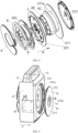
FIG. 4 shows an exploded view of the turntable in a charging pile according to an embodiment of the present application, wherein the direction indicated by arrow is the axial direction; -
FIG. 5 shows a partial explosion diagram of a charging pile provided by an embodiment of the present application, wherein the direction indicated by the arrow is the axial direction; -
FIG. 6 shows an enlarged view of a portion ofFIG. 5 ; -
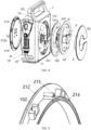
FIG. 7 is a schematic view showing an overall structure of another direction of a charging pile according to an embodiment of the present application; -
FIG. 8 shows another partial exploded view of a charging pile provided by an embodiment of the present application; -
FIG. 9 shows an enlarged partial view ofFIG. 8 . -
- 1-shell,
- 11- handle portion,
- 12- first shell, 121-first sidewall, 121a-first flange,
- 13- second shell, 131-second sidewall, 131a-second flange,
- 14- inner cavity, 15-through hole, 16-charging-slot, 17-outlet, 18-rotary drum,
- 2-turntable,
- 21- first connecting portion, 211-first connector, 211a-annular wall, 212-first end plate, 212a-rotating handle, 213- clip, 214-buckle groove, 215-screw holes,
- 22-second connecting portion, 221-second connector, 222-second end plate, 23-winding groove, 24-accommodating space,
- 3-mounting element, 31-mounting block ,32-connecting block,
- 4-charging gun, 41-charging head, 42-charging wire,
- 5-electric control assembly, 51-display screen, 52-button,
- 6-storage tray, 61-storage space, 62-slot,
- 7-clearance, 8-cable, 9-plug,
- 10-rotating element, 101 -ball, 102-ball groove.
- In order that the objects, aspects and advantages of the embodiments of the present invention will become more apparent, a more complete description of the embodiments of the present invention will be rendered by reference to the appended drawings, which are provided for purposes of illustration only and are not intended to be exhaustive or limiting of the present invention. Based on the embodiments in the present application, all the other embodiments obtained by a person of ordinary skill in the art without involving any inventive effort fall within the scope of protection of the present application.
-
FIG. 1 is a schematic view showing the overall structure of a charging pile according to an embodiment of the present application.FIG. 2 shows a cross-sectional view of a charging pile provided by an embodiment of the present application. - Referring to
FIG. 1 and2 , embodiments of the present application provide a charging pile for powering new energy vehicles. The charging pile comprises ashell 1, wherein theshell 1 encloses and forms at least oneinner cavity 14, and two throughholes 15 are provided along the transverse or longitudinal direction of theshell 1; aturntable 2, wherein at least part of theturntable 2 is rotatably arranged in theinner cavity 14 along the axial direction of the throughhole 15, and at least oneaccommodating space 24 is formed inside theturntable 2; at least oneelectric control assembly 5, wherein theelectric control assembly 5 is provided in theaccommodating space 24 and can rotate with theturntable 2; thecharging gun 4 comprises acharging head 41 and acharging wire 42, wherein one end of thecharging wire 42 is electrically connected to theelectric control assembly 5, and the other end thereof is connected to thecharging head 41. Theturntable 2 comprises a first connectingportion 21 and a second connecting portion 22, wherein the first connectingportion 21 and the second connecting portion 22 are respectively movably connected at the position of theshell 1 corresponding to the two throughholes 15; the first connectingportion 21 and the second connecting portion 22 are fitted with awire winding groove 23 for accommodating thecharging wire 42. - When a user needs to charge, the present charging pile is externally connected to mains electricity, and then the
charging wire 42 of thecharging gun 4 is pulled outwards, at this moment, theturntable 2 rotates clockwise or counterclockwise under the action of an external force, so that thecharging wire 42 received in thewire winding groove 23 can be smoothly led out, and the user can drive thecharging gun 4 to move to a charging port position where a new energy automobile is located for charging, and in this process, mains electricity such as 220V alternating current is led to theelectric control assembly 5, and theelectric control assembly 5 converts the 220V mains electricity into direct current adapted to the new energy automobile. The direct current transmits electrical energy to the new energy vehicle to be charged through thecharging gun 4. When the charging is completed, thecharging wire 42 exposed to the outside of the chargingpile shell 1 can be re-wound and received in thewinding groove 23 by simply driving theturntable 2 to rotate in a reverse direction when theturntable 2 is pulled out toward thecharging wire 42 by hand. With regard to theturntable 2 connected to theshell 1, theturntable 2 is provided as the first connectingportion 21 and the second connecting portion 22 which are oppositely matched, wherein the first connectingportion 21 and the second connecting portion 22 respectively achieve a rotary connection with theshell 1 at the positions of the throughholes 15 on opposite sides of theshell 1, and no additional driving device (such as an electric motor) is required to drive theturntable 2 to rotate, and an ordinary user can achieve the rotation of theturntable 2 relative to theshell 1 by acting on theturntable 2 with his/her hands so as to complete the storage of thecharging wire 42. Furthermore, the outer sidewall of the first connectingportion 21 and the second connecting portion 22 which are fitted in theinner cavity 14 forms at least onewire winding groove 23 for accommodating thecharging wire 42, and the inner sidewall encloses at least oneaccommodating space 24 for mounting and fixing theelectric control assembly 5. The charging pile is designed by the movable fit between theturntable 2 and theshell 1, the structural connection between the first connectingportion 21 and the second connecting portion 22, and the position where theelectric control assembly 5 is provided in theaccommodating space 24, so as to reduce the overall volume of the charging pile and meet the storage requirement of thecharging wire 42. - In an alternative embodiment, referring to
FIG.s 3 to 6 , the first connectingportion 21 comprises afirst connector 211 and afirst end plate 212, and the second connecting portion 22 comprises asecond connector 221 and asecond end plate 222; theshell 1 comprises at least onefirst sidewall 121 and at least onesecond sidewall 131 which are penetrated by the throughhole 15, thefirst connector 211 is arranged on theinner cavity 14 near thefirst sidewall 121, and thefirst end plate 212 is arranged outside theinner cavity 14 near thefirst sidewall 121; thesecond connector 221 is disposed within theinner cavity 14 adjacent to thesecond sidewall 131, and thesecond end plate 222 is disposed outside theinner cavity 14 adjacent to thesecond sidewall 131. - The movable connection of the connecting portion with the
shell 1 is achieved by the cooperation of connecting members and end plates respectively provided on both sides of the sidewall in the axial direction H, without the need for additional auxiliary driving members to drive the rotation of theturntable 2. Connectors and end plates respectively provided on the inner and outer sides of theinner cavity 14 can facilitate assembly. Thefirst end plate 212 vertically extends out of the annular extension piece towards thefirst connector 211, at least onebuckle groove 214 is provided at the end of the extension piece, thefirst connector 211 is correspondingly provided with at least oneclip 213 at the position of theannular buckle groove 214, thefirst connector 211 and thefirst end plate 212 complete a snap connection with thebuckle groove 214 via theclip 213, and thefirst sidewall 121 and the extension piece are movably fitted with each other. It is of course also possible that thefirst connector 211 extends perpendicularly out of the annular extension toward thefirst end plate 212. On the other side of theshell 1, the second connectingmember 221 and thesecond end plate 222 are connected in the same manner as thefirst connector 211 and thefirst end plate 212 described above. One of the connector and the end plate is provided with aclip 213, and the other is provided with at least onebuckle groove 214, wherein theclip 213 and thebuckle groove 214 are snap-engaged so as to detachably connect the two. However, in order to improve the strength of the connection between the two, the end plate may be provided with an annularly arranged screw holes 215, and the two may be detachably connected through the cooperation of screws and the screw holes 215. - Specifically, referring to
FIG. 3 , afirst flange 121a and asecond flange 131a in the shape of circular ring are vertically extended along the center line of the throughhole 15 from the inner sides of the sidewalls. Thefirst end plate 212 is provided at the throughhole 15 of thefirst sidewall 121 and the outer side surface of thefirst end plate 212 and the outer side surface of thefirst sidewall 121 are substantially horizontal, and thesecond end plate 222 is provided at the throughhole 15 of thesecond sidewall 131 and the outer side surface of thesecond end plate 222 and the outer side surface of thefirst sidewall 121 are substantially horizontal; thefirst flange 121a limits movement of thefirst end plate 212 toward theinner cavity 14 and thesecond flange 131a limits movement of thesecond end plate 222 toward the inner cavity14. A protruding flange structure is provided at the positions of the two sidewalls corresponding to the throughholes 15, respectively, so that when the connector is engaged with the end plate, the flange can abut against the end plate for limiting the movement of the end plate into theinner cavity 14. And referring toFIG. 8 and 9 , the connection point of thefirst connector 211 and thefirst end plate 212 is in a clearance fit with thefirst flange 121a, the connection point of thesecond connector 221 and thesecond end plate 222 is in clearance fit with thesecond flange 131a, and at least one rotatingelement 10 for facilitating the rotation of theturntable 2 is provided in theclearance 7. - When the
turntable 2 is rotated, the sidewall on the circumferential side of the throughhole 15 restricts thefirst end plate 212 and thesecond end plate 222 from moving in any direction as much as possible. In the first connectingportion 21, numerous connecting points enclose an extending piece in the shape of a ring, at least oneclearance 7 is formed between the extending piece and thefirst flange 121a, an upper portion of therotating element 10 provided in theclearance 7 abuts against thefirst flange 121a, and the lower portion abuts against the extending piece, so that there is a position restriction between thefirst sidewall 121 and the first connectingportion 21 and the first connectingportion 21 can rotate relative to thefirst sidewall 121. The first connectingportion 21 is circular, and the diameter thereof is greater than the diameter of the throughhole 15, and is adhered to the inner side of thefirst sidewall 121; thefirst end plate 212 is also circular, and the diameter thereof is slightly less than the diameter of the throughhole 15; thefirst flange 121a limits thefirst end plate 212 to move towards theinner cavity 14; and the snap connection between thefirst end plate 212 and thefirst connector 211 limits thefirst end plate 212 to move away from thefirst connector 211 in a direction away from theinner cavity 14. Of course, the engagement relationship between the second connecting portion 22 and thesecond sidewall 131 is the same as the engagement relationship between the first connecting portion 22 and thefirst sidewall 121. - Of course, it is also possible to increase the diameter of the through
hole 15 of the outer ring by removing the outer ring of the sidewall of the peripheral side of the throughhole 15 at the position of the original throughhole 15, while keeping the diameter of the inner ring of the through hole 15 (the side close to the inner cavity 14) constant, so that thefirst end plate 212 and thesecond end plate 222 can be limited to the outer ring position of the throughhole 15 outside theinner cavity 14. - The outer surface of the end panel and the outer surface of the sidewall are substantially horizontal, i.e. substantially coplanar, ensuring the aesthetics and integrity of the overall appearance.
- Alternatively, the rotating
element 10 is a plurality ofballs 101 arranged at intervals in theclearance 7, and thefirst end plate 212 and/or thesecond end plate 222 are provided with a plurality ofball grooves 102 on the peripheral side corresponding to theballs 101. Theball grooves 102 serve to restrain theballs 101 so as to prevent theballs 101 from moving out of the predetermined trajectory, and also to prevent theballs 101 from gathering locally to affect the rotation of theturntable 2. It is to be understood that therotating element 10 may be provided in other structures capable of realizing the rotation of theturntable 2 with respect to theshell 1, and is not specifically limited herein. - The
shell 1 provided therein may be integrally formed, or may comprise at least onefirst shell 12 and at least onesecond shell 13 which are detachably connected, wherein thefirst shell 12 is provided with at least onefirst sidewall 121, and thesecond shell 13 is provided with at least onesecond sidewall 131, so as to facilitate the processing and assembly of theturntable 2 of theinner cavity 14 of theshell 1. However, with regard to the specific detachable connection form of thefirst shell 12 and thesecond shell 13, in the present embodiment, in order to ensure the stability of the overall structure, thefirst shell 12 and thesecond shell 13 are fixed by means of screws, which is also very convenient when being replaced. - Optionally, the first connecting
portion 21 further comprises at least oneannular wall 211a arranged on the peripheral side of the central point of thefirst connector 211, theannular wall 211a extending perpendicularly with respect to thefirst connector 211, and the second connecting portion 22 further comprises theannular wall 211a arranged on the peripheral side of the central point of the second connectingmember 221, theannular wall 211a extending perpendicularly with respect to the second connectingmember 221; the twoannular walls 211a are oppositely arranged to enclose theaccommodating space 24, and thefirst connector 211, thesecond connector 221 and the twoannular walls 211a together define the windinggroove 23 at the outer ring of theaccommodating space 24. - The sectional shape of the
annular wall 211a may be circular, square, rectangular, triangular or other irregular shape, and the shape and size of theannular wall 211a may be appropriately selected according to the size and shape of the internalelectric control assembly 5. In the present embodiment, it is preferable that theannular wall 211a has a circular cross section, and it is convenient to provide a snap-fit structure for the circularannular wall 211a, and the outer side of theannular wall 211a serves as the inner core of theaccommodating space 24, and when the twoannular walls 211a are fitted together, the cylindricalannular wall 211a is convenient to be accommodated and labor-saving. - In the
accommodating space 24, theelectric control assembly 5 is fixed in theaccommodating space 24 so as to rotate synchronously with theturntable 2 by providing at least one fixing column at the periphery side of theelectric control assembly 5, and it is also possible to avoid knocking on theelectric control assembly 5 during rotation and influence on line winding. - In an alternative embodiment, referring to
FIG. 5 , the charging pile further comprises a control panel disposed on the outer surface of thefirst end plate 212 and electrically connected to theelectric control assembly 5; the control panel is synchronously rotatable with thefirst end plate 212, and includes at least onedisplay screen 51 andbuttons 52. Thebutton 52 is touch control button, and can adjust the prompt of reserved charging and blinking charging color, and thedisplay screen 51 can display the charging current magnitude, such as 32A, 40A, etc. and the charging duration. The reserved charging method is to start the charging after half an hour or two hours after connecting the mains power supply and the charging port of the new energy automobile. - Optionally, a
rotating handle 212a is attached perpendicularly to the outer surface of thefirst end plate 212, and therotating handle 212a is disposed near the outer edge of thefirst end plate 212. Therotating handle 212a is provided so that a user can manually rotate therotating handle 212a to achieve the rotation of theturntable 2 after using the charging pile to charge, so that thecharging wire 42 can be recycled into thewire winding groove 23; therotating handle 212a is provided away from the central point to increase the distance between the connecting line between therotating handle 212a and the central point; and the torque is increased so as to achieve the purpose of saving effort and facilitating user operation. - Optionally, at least one
outlet 17 is provided at either side away from the throughhole 15 of theshell 1,acharging wire 42 pass through the outlet,, two oppositerotary drums 18 are provided at theline outlet 17, thecharging wire 42 extends from between the tworotary drums 18, and at least onerotary drum 18 rotates as thecharging wire 42 extends; theshell 1 is provided with at least one charging-slot 16 for placing a charginghead 41, and the charging-slot 16 is provided above theoutlet 17. In the non-use state, charginghead 41 is engaged in charging-slot 16, and chargingwire 42 is accommodated in windinggroove 23. When charging is required, the user simply removes the charginghead 41 and moves the charginghead 41 so that thecharging wire 42 is in tension. Under the action of a pulling force, theturntable 2 is driven to rotate relative to theshell 1, so that thecharging wire 42 is led out of thewire winding groove 23. At the same time, therotary drum 18 rotates as thecharging wire 42 is extended, and therotary drum 18 allows thecharging wire 42 to be pulled out more smoothly and avoids damage to the charging wire due to friction with theoutlet 17. - In an alternative embodiment, reference to
FIG. 2 , at least onehandle portion 11 is provided above theshell 1, thehandle portion 11 being fixedly connected to theshell 1 or being of one-piece construction with theshell 1. It can be moved to any position for charging according to the user's requirements. - In an alternative embodiment, reference to
FIG. 5 , theshell 1 is provided outside with at least one mountingelement 3 comprising at least one mountingblock 31 fixedly connected to theshell 1, and at least one connectingblock 32 hinged to the mountingblock 31. It will be appreciated that the mountingblock 31 may be a planar sheet-like structure to be provided on only one sidewall of theshell 1, or an L-shaped structure to be secured to the sidewall and the bottom wall of theshell 1, respectively, to provide structural stability of the fixed connection, and that the connectingblock 32 may be used to be secured to a stanchion or a wall without the need to move the charging pile, the mountingblock 31 being hinged to the connectingblock 32 to enable the position and angle of the charging pile to be suitably adjusted in a fixed condition to maximise docking with a new energy vehicle. - In an alternative embodiment, with reference to
FIG.s 7-9 , at least onestorage tray 6 is fixedly connected to the outer side of thesecond end plate 222, at least onestorage space 61 is provided between thestorage tray 6 and the outer side of thesecond end plate 222, and thestorage tray 6 can rotate synchronously with thesecond end plate 222. Wherein acable 8 electrically connected to theelectric control assembly 5 is provided near thestorage tray 6, and thecable 8 is used for connecting an external power supply to supply power to the charging pile; thecable 8 is accommodated in thestorage space 61, and aslot 62 for accommodating theplug 9 of thecable 8 is provided at the intermediate position of thestorage tray 6. Thecable 8 can be received by thestorage tray 6, so that the charging pile can be moved to any position close to the power source, and then the receivedcable 8 can be taken out, so that theplug 9 and the power source can be electrified. - Finally, it should be noted that: the above-mentioned embodiments are merely illustrative of the technical solution of the present application, rather than limiting same; although the present application has been described in detail with reference to the foregoing embodiments, those skilled in the art will appreciate that: the technical solutions disclosed in the above-mentioned embodiments can still be amended, or some or all of the technical features thereof can be replaced by equivalents; however, these modifications or substitutions do not bring the essence of the corresponding technical solutions out of the scope of the technical solutions of the various embodiments of the present application.
Claims (10)
- A charging pile, comprising:a shell, wherein an inner cavity is formed by enclosing the shell, and two through holes are provided along the transverse or longitudinal direction of the shell;a turntable, at least part of the turntable being rotatably arranged in the inner cavity along the through hole axial direction, and an accommodating space being formed inside the turntable;at least one electric control assembly, wherein the electric control assembly is provided in the accommodating space and can rotate with the turntable;at least one charging gun comprising a charging head and a charging wire, wherein one end of the charging wire is electrically connected to the electric control assembly, and the other end is connected to the charging head;the turntable comprises a first connecting portion and a second connecting portion, wherein the first connecting portion and the second connecting portion are respectively movably connected at the positions of the shells corresponding to the two through holes; a wire winding groove for accommodating the charging wire is formed in cooperation with the first connecting portion and the second connecting portion.
- The charging pile according to claim 1, wherein the first connecting portion comprises a first connector and a first end plate, and the second connecting portion comprises a second connector and a second end plate;
the shell includes a first sidewall and a second sidewall that are penetrated by the through hole, the first connector is disposed in the inner cavity near the first sidewall, and the first end plate is disposed outside the inner cavity near the first sidewall; the second connector is disposed in the inner cavity proximate to the second sidewall and the second end plate is disposed outside the inner cavity proximate to the second sidewall. - The charging pile according to claim 2, wherein the first connecting portion further comprises an annular wall provided on the center point peripheral side of the first connector, the annular wall extending vertically with respect to the first connector, and the second connecting portion further comprises an annular wall provided on the center point peripheral side of the second connector, the annular wall extending vertically with respect to the second connecting member;
the two annular walls are oppositely arranged to enclose the accommodating space, and the first connector, the second connector and the outer ring of the two annular walls in the accommodating space together define the wire winding groove. - The charging pile according to claim 3, wherein a first flange and a second flange in the shape of a circular ring are vertically extended along the center line of the through hole on the inner side of both the sidewalls;the first end plate is provided at the through hole of the first sidewall and the outer side surface of the first end plate and the outer side surface of the first sidewall are substantially horizontal, and the second end plate is provided at the through hole of the second sidewall and the outer side surface of the second end plate and the outer side surface of the first sidewall are substantially horizontal;the first flange limits movement of the first end plate toward the inner cavity and the second flange limits movement of the second end plate toward the inner cavity.
- The charging pile according to claim 4, wherein at least one connection point of the first connector and the first end plate is in a clearance fit with the first flange, at least one connection point of the second connector and the second end plate is in a clearance fit with the second flange, and at least one rotating element for facilitating rotation of the turntable is provided in the clearance.
- The charging pile according to claim 5, wherein the rotating element is a plurality of balls arranged at intervals in the clearance, and the first end plate and/or the second end plate is provided with a plurality of ball grooves corresponding to the balls on their circumferential side thereof.
- The charging pile according to claim 2, wherein further comprising a control panel disposed on the outer surface of the first end plate and electrically connected to the electric control assembly;
the control panel is synchronously rotatable with the first end plate, the control panel including at least one display screen and buttons. - The charging pile according to any one of claims 2-7, wherein that a rotating handle is vertically connected to the outer surface of the first end plate, the rotating handle being arranged near the outer edge of the first end plate; and/or, an outlet is provided at either side away from the through hole of the shell, the charging wire pass through the outlet, two opposite rotary drums are provided at the line outlet, the charging wire protrudes from between the two rotary drums, and at least one of the rotary drums rotates as the charging wire protrudes; the shell is provided with at least one charging-slot for placing the charging head, and the charging-slot is provided above the outlet; and/or,at least one handle portion is provided above the shell, the handle portion is fixedly connected to the shell or the handle portion and the shell are of an integral structure; and/or,at least one mounting element is provided outside the shell and includes at least one mounting block fixedly connected to the shell and at least one connecting block hinged to the mounting block.
- The charging pile according to any one of claims 2-7, wherein at least one storage tray is fixedly connected to the outer side of the second end plate, wherein at least one storage space is provided between the storage tray and the outer side of the second end plate, and wherein the storage tray can rotate synchronously with the second end plate.
- The charging pile according to claim 9, wherein a cable electrically connected to the electric control assembly is provided near the storage tray, the cable being used for connecting external power supply to power the charging pile;
the cable is accommodated in the storage space, and a slot for accommodating a plug of the cable is provided at the intermediate position of the storage tray.
Applications Claiming Priority (1)
| Application Number | Priority Date | Filing Date | Title |
|---|---|---|---|
| CN202223213491.7U CN219007631U (en) | 2022-11-30 | 2022-11-30 | Charging pile |
Publications (1)
| Publication Number | Publication Date |
|---|---|
| EP4379985A1 true EP4379985A1 (en) | 2024-06-05 |
Family
ID=86246128
Family Applications (1)
| Application Number | Title | Priority Date | Filing Date |
|---|---|---|---|
| EP23175682.6A Pending EP4379985A1 (en) | 2022-11-30 | 2023-05-26 | Charging pile |
Country Status (3)
| Country | Link |
|---|---|
| US (1) | US20240174100A1 (en) |
| EP (1) | EP4379985A1 (en) |
| CN (1) | CN219007631U (en) |
Citations (5)
| Publication number | Priority date | Publication date | Assignee | Title |
|---|---|---|---|---|
| DE10224472A1 (en) * | 2002-06-03 | 2003-12-11 | Max Speckhart | Cable drum for holding an extension cable has one or more plug sockets to accept direct or alternating current appliances with 6, 12 or 24 volts |
| US20040087207A1 (en) * | 2002-09-11 | 2004-05-06 | Oliver Lerch | Electrical extension lead |
| US20150008878A1 (en) * | 2012-02-01 | 2015-01-08 | Chuo Hatsujo Kabushiki Kaisha | Charging-cable storage device |
| CN111162418A (en) * | 2020-01-20 | 2020-05-15 | 中航光电科技股份有限公司 | Take-up control box |
| DE202020102671U1 (en) * | 2019-05-13 | 2021-01-27 | R.M.D. Components Italia S.R.L. | Winding device for a power supply cable for drive vehicles |
-
2022
- 2022-11-30 CN CN202223213491.7U patent/CN219007631U/en active Active
-
2023
- 2023-05-23 US US18/322,012 patent/US20240174100A1/en active Pending
- 2023-05-26 EP EP23175682.6A patent/EP4379985A1/en active Pending
Patent Citations (5)
| Publication number | Priority date | Publication date | Assignee | Title |
|---|---|---|---|---|
| DE10224472A1 (en) * | 2002-06-03 | 2003-12-11 | Max Speckhart | Cable drum for holding an extension cable has one or more plug sockets to accept direct or alternating current appliances with 6, 12 or 24 volts |
| US20040087207A1 (en) * | 2002-09-11 | 2004-05-06 | Oliver Lerch | Electrical extension lead |
| US20150008878A1 (en) * | 2012-02-01 | 2015-01-08 | Chuo Hatsujo Kabushiki Kaisha | Charging-cable storage device |
| DE202020102671U1 (en) * | 2019-05-13 | 2021-01-27 | R.M.D. Components Italia S.R.L. | Winding device for a power supply cable for drive vehicles |
| CN111162418A (en) * | 2020-01-20 | 2020-05-15 | 中航光电科技股份有限公司 | Take-up control box |
Also Published As
| Publication number | Publication date |
|---|---|
| CN219007631U (en) | 2023-05-12 |
| US20240174100A1 (en) | 2024-05-30 |
Similar Documents
| Publication | Publication Date | Title |
|---|---|---|
| US20250319783A1 (en) | Portable electric vehicle charger | |
| US12219929B1 (en) | Rollable ball toy | |
| EP2779339A1 (en) | Cable housing device | |
| US20240174100A1 (en) | Charging pile | |
| CN115441271A (en) | Vehicle-mounted USB data line | |
| WO2021213347A1 (en) | Automatic wire taking-up device | |
| CN206023277U (en) | Charging of mobile devices device | |
| CN210225702U (en) | bluetooth earphone charging box | |
| CN116461361A (en) | Charging pile | |
| KR20130043268A (en) | Cord reel apparatus | |
| CN209610143U (en) | A kind of electric trunk | |
| CN208986325U (en) | An intelligent retractable data cable | |
| KR20140119967A (en) | Multi-functional power cable reel assembly | |
| CN220983523U (en) | Metal detector | |
| CN223156715U (en) | A charging device | |
| CN208748561U (en) | A kind of berth lock based on human body sensing | |
| CN214205007U (en) | Flexible centre gripping formula removes battery charging outfit | |
| CN204243845U (en) | Charging device and electric motor car | |
| CN107366630A (en) | The Portable fan and fan component of a kind of built-in lithium battery | |
| CN220360672U (en) | Chest expander casing and chest expander | |
| CN216190125U (en) | Electric shock prevention cable winding machine | |
| WO2020228012A1 (en) | Button assembly, reeling apparatus, and flexible keyboard | |
| CN222692010U (en) | A portable navigation control box | |
| CN222852038U (en) | Novel mobile power supply | |
| CN222127686U (en) | A charging device |
Legal Events
| Date | Code | Title | Description |
|---|---|---|---|
| PUAI | Public reference made under article 153(3) epc to a published international application that has entered the european phase |
Free format text: ORIGINAL CODE: 0009012 |
|
| STAA | Information on the status of an ep patent application or granted ep patent |
Free format text: STATUS: THE APPLICATION HAS BEEN PUBLISHED |
|
| STAA | Information on the status of an ep patent application or granted ep patent |
Free format text: STATUS: REQUEST FOR EXAMINATION WAS MADE |
|
| AK | Designated contracting states |
Kind code of ref document: A1 Designated state(s): AL AT BE BG CH CY CZ DE DK EE ES FI FR GB GR HR HU IE IS IT LI LT LU LV MC ME MK MT NL NO PL PT RO RS SE SI SK SM TR |
|
| 17P | Request for examination filed |
Effective date: 20240521 |
|
| RBV | Designated contracting states (corrected) |
Designated state(s): AL AT BE BG CH CY CZ DE DK EE ES FI FR GB GR HR HU IE IS IT LI LT LU LV MC ME MK MT NL NO PL PT RO RS SE SI SK SM TR |