EP4379968A1 - Female terminal, connector, terminal-attached electrical wire, connector-attached electrical wire, and wire harness - Google Patents
Female terminal, connector, terminal-attached electrical wire, connector-attached electrical wire, and wire harness Download PDFInfo
- Publication number
- EP4379968A1 EP4379968A1 EP22849480.3A EP22849480A EP4379968A1 EP 4379968 A1 EP4379968 A1 EP 4379968A1 EP 22849480 A EP22849480 A EP 22849480A EP 4379968 A1 EP4379968 A1 EP 4379968A1
- Authority
- EP
- European Patent Office
- Prior art keywords
- side wall
- female terminal
- welded
- welding
- terminal
- Prior art date
- Legal status (The legal status is an assumption and is not a legal conclusion. Google has not performed a legal analysis and makes no representation as to the accuracy of the status listed.)
- Pending
Links
- 238000003466 welding Methods 0.000 claims description 162
- 238000000034 method Methods 0.000 description 16
- 238000003780 insertion Methods 0.000 description 14
- 230000037431 insertion Effects 0.000 description 14
- 238000005452 bending Methods 0.000 description 8
- 238000005336 cracking Methods 0.000 description 8
- 239000000463 material Substances 0.000 description 6
- 238000007747 plating Methods 0.000 description 5
- 230000015572 biosynthetic process Effects 0.000 description 2
- 239000012141 concentrate Substances 0.000 description 2
- 239000007787 solid Substances 0.000 description 2
- 229910000838 Al alloy Inorganic materials 0.000 description 1
- 229910000881 Cu alloy Inorganic materials 0.000 description 1
- BQCADISMDOOEFD-UHFFFAOYSA-N Silver Chemical compound [Ag] BQCADISMDOOEFD-UHFFFAOYSA-N 0.000 description 1
- ATJFFYVFTNAWJD-UHFFFAOYSA-N Tin Chemical compound [Sn] ATJFFYVFTNAWJD-UHFFFAOYSA-N 0.000 description 1
- 239000011324 bead Substances 0.000 description 1
- 238000005219 brazing Methods 0.000 description 1
- 239000004020 conductor Substances 0.000 description 1
- 230000000694 effects Effects 0.000 description 1
- 230000002349 favourable effect Effects 0.000 description 1
- 239000000835 fiber Substances 0.000 description 1
- 229910052709 silver Inorganic materials 0.000 description 1
- 239000004332 silver Substances 0.000 description 1
- 238000005476 soldering Methods 0.000 description 1
Images












Classifications
-
- H—ELECTRICITY
- H01—ELECTRIC ELEMENTS
- H01R—ELECTRICALLY-CONDUCTIVE CONNECTIONS; STRUCTURAL ASSOCIATIONS OF A PLURALITY OF MUTUALLY-INSULATED ELECTRICAL CONNECTING ELEMENTS; COUPLING DEVICES; CURRENT COLLECTORS
- H01R13/00—Details of coupling devices of the kinds covered by groups H01R12/70 or H01R24/00 - H01R33/00
- H01R13/02—Contact members
- H01R13/15—Pins, blades or sockets having separate spring member for producing or increasing contact pressure
- H01R13/187—Pins, blades or sockets having separate spring member for producing or increasing contact pressure with spring member in the socket
-
- H—ELECTRICITY
- H01—ELECTRIC ELEMENTS
- H01R—ELECTRICALLY-CONDUCTIVE CONNECTIONS; STRUCTURAL ASSOCIATIONS OF A PLURALITY OF MUTUALLY-INSULATED ELECTRICAL CONNECTING ELEMENTS; COUPLING DEVICES; CURRENT COLLECTORS
- H01R13/00—Details of coupling devices of the kinds covered by groups H01R12/70 or H01R24/00 - H01R33/00
- H01R13/02—Contact members
- H01R13/10—Sockets for co-operation with pins or blades
- H01R13/11—Resilient sockets
-
- H—ELECTRICITY
- H01—ELECTRIC ELEMENTS
- H01R—ELECTRICALLY-CONDUCTIVE CONNECTIONS; STRUCTURAL ASSOCIATIONS OF A PLURALITY OF MUTUALLY-INSULATED ELECTRICAL CONNECTING ELEMENTS; COUPLING DEVICES; CURRENT COLLECTORS
- H01R13/00—Details of coupling devices of the kinds covered by groups H01R12/70 or H01R24/00 - H01R33/00
- H01R13/02—Contact members
- H01R13/10—Sockets for co-operation with pins or blades
-
- H—ELECTRICITY
- H01—ELECTRIC ELEMENTS
- H01R—ELECTRICALLY-CONDUCTIVE CONNECTIONS; STRUCTURAL ASSOCIATIONS OF A PLURALITY OF MUTUALLY-INSULATED ELECTRICAL CONNECTING ELEMENTS; COUPLING DEVICES; CURRENT COLLECTORS
- H01R13/00—Details of coupling devices of the kinds covered by groups H01R12/70 or H01R24/00 - H01R33/00
- H01R13/02—Contact members
- H01R13/10—Sockets for co-operation with pins or blades
- H01R13/11—Resilient sockets
- H01R13/113—Resilient sockets co-operating with pins or blades having a rectangular transverse section
-
- H—ELECTRICITY
- H01—ELECTRIC ELEMENTS
- H01R—ELECTRICALLY-CONDUCTIVE CONNECTIONS; STRUCTURAL ASSOCIATIONS OF A PLURALITY OF MUTUALLY-INSULATED ELECTRICAL CONNECTING ELEMENTS; COUPLING DEVICES; CURRENT COLLECTORS
- H01R4/00—Electrically-conductive connections between two or more conductive members in direct contact, i.e. touching one another; Means for effecting or maintaining such contact; Electrically-conductive connections having two or more spaced connecting locations for conductors and using contact members penetrating insulation
- H01R4/02—Soldered or welded connections
- H01R4/029—Welded connections
-
- H—ELECTRICITY
- H01—ELECTRIC ELEMENTS
- H01R—ELECTRICALLY-CONDUCTIVE CONNECTIONS; STRUCTURAL ASSOCIATIONS OF A PLURALITY OF MUTUALLY-INSULATED ELECTRICAL CONNECTING ELEMENTS; COUPLING DEVICES; CURRENT COLLECTORS
- H01R43/00—Apparatus or processes specially adapted for manufacturing, assembling, maintaining, or repairing of line connectors or current collectors or for joining electric conductors
- H01R43/16—Apparatus or processes specially adapted for manufacturing, assembling, maintaining, or repairing of line connectors or current collectors or for joining electric conductors for manufacturing contact members, e.g. by punching and by bending
Definitions
- the present invention relates to a female terminal of an electric circuit through which a large current flows, a connector, a terminal-attached electric wire, a connector-attached electric wire, and a wire harness.
- An electric device conventionally constitutes an electric circuit by connecting an electric device and a power supply device with a wire harness.
- the wire harness and the electric device as well as the wire harness and the power supply device are connected to each other via connectors attached to the respective devices.
- a female terminal is housed in a connector housing.
- a terminal body is formed of a base portion and a spring member, and when a male terminal is inserted, an arm spring that is a part of the spring member deform to bend.
- Patent Literature 1 JP 2009-245701 A
- An object of the present invention is to provide a female terminal, a connector, a terminal-attached electric wire, a connector-attached electric wire, and a wire harness capable of preventing an excessive load from acting on a welded portion between a base portion and a spring member.
- the present invention is a female terminal including a terminal body, the terminal body including a base portion to be connected to an electric wire, and a spring member that is attached to the base portion, in which the base portion includes a pair of side walls disposed at a predetermined interval into which a male terminal can be inserted, the spring member includes a laying plate along at least an inner side surface of each of the side walls and an arm spring extending from the laying plate toward the side wall facing the laying plate, the side wall and the laying plate are welded to form a welded portion, and a fulcrum portion of the arm spring abutting the side wall is provided between the welded portion and a contact portion of the arm spring.
- the contact portion in the present invention refers to a portion at a distal end of the arm spring, the portion abutting a male terminal in a state where the male terminal is inserted inside the female terminal.
- the fulcrum portion in the present invention refers to a portion at a proximal end of the arm spring, the portion abutting a side wall in a state where a male terminal is inserted at least inside the female terminal.
- the term "between the welded portion and the contact portion of the arm spring” in the present invention refers to a range sandwiched between the welded portion and the contact portion in a state where the spring member formed by bending the base material is developed in a flat plate shape.
- the present invention also includes a connector including the female terminal and a connector housing that houses the female terminal, and a terminal-attached electric wire including the female terminal and the electric wire connected to the base portion of the female terminal.
- the present invention further includes a connector-attached electric wire including the terminal-attached electric wire and a connector housing that houses the terminal-attached electric wire, and a wire harness including at least one of the terminal-attached electric wire and the connector-attached electric wire.
- the present invention can prevent an excessive load from acting on the welded portion between the base portion and the spring member.
- a fulcrum portion of the arm spring abutting the side wall is provided between the welded portion and the contact portion of the arm spring.
- a current flows through a short path. That is, when a current flows from the male terminal to the female terminal, the current flows from the contact portion abutting the male terminal to the side wall via the arm spring and through the fulcrum portion. When a current flows from the female terminal to the male terminal, the current flows from the fulcrum portion abutting the side wall to the male terminal via the arm spring and through the contact portion. Thus, electric resistance at these terminals can be held low.
- Such a structure can be said to be a structure particularly suitable for an electric circuit through which a large current flows.
- the laying plate may be disposed along a distal end surface of the side wall, and the laying plate may be welded to the distal end surface of the side wall.
- the distal end surface in the present invention refers to a surface intersecting an insertion direction of the male terminal in at least one side wall of the pair of side walls.
- the laying plate in the present invention is a part of the spring member disposed along the distal end surface of the side wall so as to cover the distal end surface of the side wall, and it corresponds to a flange plate to be described later.
- the fulcrum portion is not displaced in a state of abutting the side wall, and thus the arm spring deforms on the contact portion side from the fulcrum portion, which suppresses the deformation of the laying plate on the welded portion side from the fulcrum portion.
- the load does not affect the laying plate along the distal end surface of the side wall.
- the portion where the laying plate overlaps the distal end surface of the side wall has a shape having a narrow width and a long length, and thus it is preferable to perform linear or dotted welding.
- the laying plate may be disposed along an outer side surface of the side wall, and the laying plate may be welded to the outer side surface of the side wall.
- the outer side surface in the present invention refers to a surface of at least one side wall of the pair of side walls, the surface being on the opposite side of the surface facing a side surface of the male terminal.
- the laying plate in the present invention is a part of the spring member disposed along the outer side surface of the side wall so as to cover the outer side surface of the side wall, and it corresponds to an outer plate to be described later.
- the fulcrum portion is not displaced in a state of abutting the side wall, and thus the arm spring deforms on the contact portion side from the fulcrum portion, which suppresses the deformation of the laying plate on the welded portion side from the fulcrum portion.
- the load does not affect the laying plate along the outer side surface of the side wall.
- the welding machine that performs these welding can freely approach and move.
- the portion where the laying plate overlaps the outer side surface of the side wall has a shape having a wide width and a long length, and thus any welding mode can be applied.
- the laying plate may be disposed along an inner side surface of the side wall, and the laying plate may be welded to the inner side surface of the side wall.
- the inner side surface in the present invention refers to a surface of at least one side wall of the pair of side walls, the surface facing a side surface of the male terminal.
- the laying plate in the present invention is a part of the spring member disposed along the inner side surface of the side wall so as to cover the inner side surface of the side wall, and it corresponds to an inner plate to be described later.
- the fulcrum portion is not displaced in a state of abutting the side wall, and thus the arm spring deforms on the contact portion side from the fulcrum portion, which suppresses the deformation of the laying plate on the welded portion side from the fulcrum portion.
- the laying plate is welded to the inner side surface of the side wall, deformation of the laying plate can be suppressed by devising the welding mode.
- the welded portion in at least one side wall of the pair of side walls may include a plurality of welded portions or a plurality of welded points.
- the plurality of welded points in the present invention refer to a plurality of linear or curved welded points. However, these welded points are not limited to welded points being parallel to each other.
- the plurality of welded points in the present invention refer to a plurality of welded points having a solid line shape, a dotted line shape, or a point group shape. However, the shape of each welded point is not limited.
- the present invention can prevent a load from concentrating on a specific welded portion.
- a load is concentrated on a specific welded portion and the welded portion is broken or the like, it is possible to prevent the welded portion from being broken or the like as a whole.
- conductivity can be stabilized.
- a parallel circuit is configured locally because a current flows through corresponding welded portions. Thus, electric resistance at these terminals can be held low.
- Such a structure can also be said to be a structure particularly suitable for an electric circuit through which a large current flows.
- the fulcrum portion of the arm spring may be a portion that abuts a protruding portion provided on the laying plate and protruding toward the side wall or a protruding portion provided on the side wall and protruding toward the laying plate.
- the protruding portion refers to a portion that locally protrudes due to bending or formation of a raised portion when provided on the laying plate. It refers to a portion that locally protrudes due to bending or formation of a raised portion also when provided on the side wall.
- a cross-sectional shape of the portion is not limited to an arc shape.
- the vertex of the protruding portion reliably abuts the side wall.
- the vertex of the protruding portion reliably abuts the laying plate.
- the welded portion in at least one side wall of the pair of side walls may form one or a plurality of curved or bent-line-shaped welding patterns.
- the curved or bent-line-shaped welding pattern in the present invention refers to a pattern having one or more curved points or bending points.
- a specific aspect of the pattern having one or more curved points or bending points is not limited.
- the strength against a load can improve.
- conductivity can improve.
- Such a structure can also be said to be a structure particularly suitable for an electric circuit through which a large current flows.
- the load acts in a distributed manner for each section in the welding line, it is possible to prevent the welded portion from being broken or the like as a whole even when the load concentrates on a specific section and the welded portion is broken or the like. Thus, conductivity can also be stabilized.
- the welded portion in at least one side wall of the pair of side walls may form a welding pattern with an end in which one or a plurality of end portions are widened.
- the welding pattern with an end in the present invention refers to an open pattern in which a start point and an end point of a welding line are not connected to the same welding line and do not intersect at a middle portion of the welding line.
- a specific aspect of the open pattern is not limited.
- the start point and the end point of the welding line are wider than other portions of the welding line, the strength of the start point and the end point against the load can be improved.
- the start point and the end point are widened, they can be formed in a straight line shape, and thus can be applied to a narrow region of the laying plate.
- the welded portion in at least one side wall of the pair of side walls may form one or a plurality of endless welding patterns.
- the endless welding pattern in the present invention refers to a totally or partially closed pattern (closed loop pattern) formed by connecting a start point and an end point of a welding line to the same welding line.
- the present invention is not limited to a specific aspect of the totally closed pattern and the partially closed pattern.
- the start point and the end point of the welding line do not appear as end portions of the welding line, it is possible to prevent an excessive load (including fatigue due to repeated stress) from acting on these start point and end point.
- an excessive load including fatigue due to repeated stress
- the welding line has a totally or partially closed pattern, the fatigue strength can be improved even against vibration from any direction.
- the welding pattern may be formed by disposing an end point of a continuous welding line at a start point of the welding line.
- the continuous welding line in the present invention refers to a solid welding line.
- disposing an end point of a continuous welding line at a start point of the welding line means that the coordinates of the start point of the welding line coincide with the coordinates of the end point.
- the welding line (so-called bead) has a totally or partially closed pattern, and the coordinates are not limited to complete matching.
- the welding machine when welding is performed from the start point to the end point of the welding line, the welding machine returns to the same position, and thus, the lead time in the welding process can be shortened.
- the female terminal is sent to the welding machine one after another, and it is necessary to weld the base portion of the female terminal and the spring member sequentially, but the end point of the welding process for one female terminal and the start point of the welding process for the next female terminal are the same, and it is not necessary to move the welding machine, which can shorten the lead time in the welding process.
- the welding pattern may be formed such that a continuous welding line passes through a start point of the welding line, and an end point of the welding line may be disposed in a middle portion of the welding line.
- the continuous welding line in the present invention also refers to a solid welding line.
- a welding line passing through a start point of the welding line means that the coordinates of the start point of the welding line coincide with the coordinates at one time point in the middle portion, and an end point of the welding line being disposed in a middle portion of the welding line means that the coordinates at one time point in the middle portion of the welding line coincide with the coordinates at the end point.
- the coordinates are not limited to complete matching.
- the length of the welding line is relatively shortened while a closed pattern is formed, and thus, the lead time in the welding process can be shortened.
- the length of the welding line is relatively short, and the welding machine can be moved at a relatively fast speed from the end point of the welding process for one female terminal to the start point of the welding process for the next female terminal, which can shorten the lead time in the welding process.
- Fig. 1 is an overall perspective view illustrating a connector 1.
- a connector housing 4 that houses a female terminal 10 is indicated by a broken line.
- Fig. 2 is an exploded perspective view of the female terminal 10.
- Fig. 3 is a perspective view of the female terminal 10.
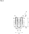
- Fig. 4 is a side view of the female terminal 10
- Fig. 5 is a front view of the female terminal 10
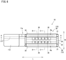
- Fig. 6 is a plan view of the female terminal 10.
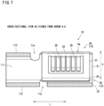
- Fig. 7 is a cross-sectional view as viewed from the arrow A-A in Fig. 6
- Fig. 8 includes a cross-sectional view as viewed from the arrow B-B and a cross-sectional view as viewed from the arrow C-C in Fig. 6 .
- Fig. 9 is an enlarged cross-sectional view of the female terminal 10
- Fig. 10 is an enlarged cross-sectional view of a state in which a male terminal 5 is inserted inside the female terminal 10.
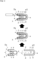
- Fig. 11 is an assembly explanatory view of the female terminal 10.
- the connector 1 is attached to a distal end of an electric wire 3 constituting a wire harness 2.
- an electric wire 3 constituting a wire harness 2.
- two female terminals 10 are housed in the connector housing 4 in parallel.
- the wire harness 2 is configured by bundling a plurality of electric wires 3.
- the electric wire 3 is formed by covering a core wire 3a which is an electric conductor with an insulating cover 3b, and the core wire 3a exposed at a distal end of the electric wire 3 is connected to a base portion 20 of the female terminal 10.
- the connector housing 4 includes an electric wire insertion portion 41 through which the electric wire 3 is inserted and a terminal housing portion 42 that houses the female terminal 10.
- a housing space 4S in which the female terminal 10 is housed is open in a substantially quadrangular shape, and a protruding portion of the connector housing that houses the male terminal 5 (see Fig. 9 ) is fitted into the opening. At this time, the male terminal 5 is inserted into the female terminal 10, and the terminals are electrically connected to each other.
- the female terminal 10 includes an electric wire connection portion 11 and a terminal connection portion 12.
- the electric wire connection portion 11 and the terminal connection portion 12 are provided in series on an extension line of the electric wire 3.
- a direction parallel to the direction in which the male terminal 5 (see Fig. 10 ) is inserted is referred to as a height direction H
- a direction orthogonal to the longitudinal direction L and the height direction H is referred to as a width direction W.
- the electric wire connection portion 11 is provided with a connection plate 111 perpendicular to the width direction W. An upper end and a lower end of the connection plate 111 are bent to provide guide pieces 112. Each of the guide pieces 112 has a role of suppressing expansion of the core wires 3a connected to the connection plate 111.
- the terminal connection portion 12 is provided with a terminal body 13 to be electrically connected to the male terminal 5.
- the terminal body 13 includes a base portion 20 integrally formed including the electric wire connection portion 11 and a spring member 30 to be attached to the base portion 20.
- the base portion 20 and the spring member 30 will be described in detail.
- the base portion 20 has a pair of side walls 21 disposed at a predetermined interval into which the male terminal 5 can be inserted. More specifically, the base portion 20 has a pair of side walls 21 separated by a predetermined interval perpendicular to the width direction W. The base portion 20 has a bottom wall 22 that connects lower ends of the respective side walls 21. Thus, the base portion 20 has a substantially U shape as viewed in the longitudinal direction L (see Fig. 4 ).
- the side wall 21 on one side of the base portion 20 is formed by extending the connection plate 111 in the longitudinal direction L.
- the side wall 21 on the other side is formed by folding back a plate material (base material of the base portion 20) to the side where the guide pieces 112 are formed.
- the base portion 20 has a substantially rectangular shape as viewed in the height direction H (see Fig. 6 ). In this manner, the base portion 20 achieves downsizing of the female terminal 10 by forming the side wall 21 on the other side on the side where the guide pieces 112 are formed.
- the guide piece 112 on the upper side of the base portion 20 is formed by bending the upper end of the connection plate 111 and is provided with a cutout portion 11a so that the side wall 21 is not distorted when the guide piece 112 is formed.
- the guide piece 112 on the lower side of the base portion 20 is formed by bending the lower end of the connection plate 111 and is provided with a cutout portion 11b so that the side wall 21 is not distorted when the guide piece 112 is formed.
- a part of the spring member 30 is exposed at the cutout portion 11b, and the spring member 30 can be pushed out and removed from the lower side (see Fig. 5 ).
- the base portion 20 is formed by being cut out from a plate material having conductivity such as a copper alloy or an aluminum alloy and being bent.
- the base portion 20 is not plated on its surface, but the base portion 20 is not limited to this configuration.
- the surface may be subjected to plating treatment such as silver plating or tin plating for improving conductivity.
- plating may be partially performed.
- one in which one surface of the electric wire connection portion 11 or the terminal connection portion 12 is plated can be considered as the base portion in which the plating treatment is partially performed.
- only the electric wire connection portion 11 may be plated, or only the terminal connection portion 12 may be plated.
- the spring member 30 has an inner plate 31 along the inner side surface 21a of the side wall 21 in a state of being fitted between the pair of side walls 21.
- the spring member 30 also has an outer plate 32 along the outer side surface 21b of the side wall 21.
- the spring member 30 has a flange plate 33 that connects upper ends of the inner plate 31 and the outer plate 32.
- the spring member 30 has a bottom plate 34 connecting lower ends of the respective inner plates 31.
- the spring member 30 has a substantially M shape as viewed in the longitudinal direction L (see Fig. 4 ).
- the inner plate 31 on one side of the spring member 30 extends in the longitudinal direction L along the opening end edge of the side wall 21, and six arm springs 35 extend from the inner plate 31 toward the opposing side wall 21 (see Fig. 7 ). All the arm springs 35 have the same shape, and specifically, they extend obliquely downward so as to approach the opposing side wall 21 as viewed in the longitudinal direction L and have a shape in which a part including a distal end edge thereof is folded back (see Fig. 8 ).
- the arm spring 35 provided on the inner plate 31 on one side extends from the lower end edge of the inner plate 31 along the opening end edge of the side wall 21, and a boundary portion with the inner plate 31 serves as a fulcrum portion Pp (see Fig. 8 ).
- the fulcrum portion Pp In the female terminal 10, the fulcrum portion Pp always abuts the inner side surface 21a of the side wall 21. However, the fulcrum portion Pp may abut with deformation when the male terminal 5 is inserted into the female terminal 10.
- the inner plate 31 on the other side of the spring member 30 also extends in the longitudinal direction L along the opening end edge of the side wall 21, and six arm springs 35 extend from the inner plate 31 toward the opposing side wall 21 (see Fig. 7 ). All the arm springs 35 have the same shape, and specifically, they extend obliquely downward so as to approach the opposing side wall 21 as viewed in the longitudinal direction L and have a shape in which a part including a distal end edge thereof is folded back (see Fig. 8 ).
- the arm spring 35 provided on the inner plate 31 on the other side also extends from the lower end edge of the inner plate 31 along the opening end edge of the side wall 21, and a boundary portion with the inner plate 31 serves as a fulcrum portion Pp (see Fig. 8 ).
- the fulcrum portion Pp In the female terminal 10, the fulcrum portion Pp always abuts the inner side surface 21a of the side wall 21. However, the fulcrum portion Pp may abut with deformation when the male terminal 5 is inserted into the female terminal 10.
- the flange plate 33 is in surface contact with a distal end surface 21c of the side wall 21. Welding is performed along the longitudinal direction L in the area in surface contact. Thus, a linear welded portion Pw is formed on the flange plate 33 (see Figs. 6 to 9 ).
- the welded portion Pw is a portion where a part of the side wall 21 or the flange plate 33 is melted, cooled, and solidified again.
- a center line C of the welded portion Pw is perpendicular to the distal end surface 21c of the side wall 21 and the flange plate 33.
- the fulcrum portion Pp is provided between the welded portion Pw and a contact portion Pc of the arm spring 35 (see a range R in Fig. 9 ).
- the fulcrum portion Pp is provided in the range R sandwiched between the welded portion Pw and the contact portion Pc. According to such a configuration, even when the contact portion Pc is pushed by the insertion of the male terminal 5 (see the arrow Fi in Fig.
- the fulcrum portion Pp is not displaced in a state of abutting the side wall 21, and thus the arm spring 35 deforms on the contact portion Pc side from the fulcrum portion Pp (see the two dot chain line D in Fig. 10 ), which suppresses the deformation of the inner plate 31 on the welded portion Pw side from the fulcrum portion Pp.
- a relationship of L1 ⁇ L2 is preferably established where L1 is a length from the distal end surface 21c of the side wall 21 to the fulcrum portion Pp of the arm spring 35, and L2 is a length from the fulcrum portion Pp of the arm spring 35 to the contact portion Pc.
- the fulcrum portion Pp serves a function of electrically connecting the arm spring 35 and the side wall 21.
- the current flows from the contact portion Pc abutting the male terminal 5 to the side wall 21 via the arm spring 35 and through the fulcrum portion Pp (see the arrows A in Fig. 10 ).
- the current flows from the fulcrum portion Pp abutting the side wall 21 to the male terminal 5 via the arm spring 35 and through the contact portion Pc (see the arrows A in Fig. 10 ).
- a current flows through the welded portion Pw close to the fulcrum portion Pp.
- the female terminal 10 is assembled as follows. That is, as illustrated in Fig. 11 , the spring member 30 is disposed on the upper side of the base portion 20, the inner plate 31 and the bottom plate 34 are fitted between the pair of side walls 21, and welding is performed to assemble the female terminal 10 in a state where the flange plate 33 is brought into surface contact with the distal end surface 21c of the side wall 21.
- the female terminal 10 is configured such that a relationship of d ⁇ D is established where d is a width dimension from the opening end edge of the side wall 21 on one side to the opening end edge of the side wall 21 on the other side, and D is a width dimension from the opening end edge of the inner plate 31 on one side to the opening end edge of the inner plate 31 on the other side.
- the female terminal 10 is configured such that a relationship of h ⁇ H is established where h is a height dimension from the inner side surface of the bottom wall 22 to the distal end surface 21c of the side wall 21, and H is a height dimension from the bottom plate 34 to the flange plate 33.
- the female terminal 10 according to another embodiment will be described with reference to Fig. 12 .
- the outer plate 32 is welded to the outer side surface 21b of the side wall 21.
- the fulcrum portion Pp is provided between the welded portion Pw and the contact portion Pc of the arm spring 35 (see the range R in Fig. 12 ).
- L1 ⁇ L2 it is preferable that a relationship of L1 ⁇ L2 is established where L1 is a length from the center line C of the welded portion Pw to the fulcrum portion Pp of the arm spring 35, and L2 is a length from the fulcrum portion Pp of the arm spring 35 to the contact portion Pc.
- a rotational force about the fulcrum portion Pp is generated by applying a load to the contact portion Pc of the arm spring 35, and even when a load that rises from the inner side surface 21a acts on the inner plate 31 closer to the welded portion Pw than the fulcrum portion Pp, the load does not affect the outer plate 32 parallel to the inner plate 31. That is, it is considered that the outer plate 32 does not deform to rise from the outer side surface 21b.
- the female terminal 10 according to another embodiment will be described with reference to Fig. 13 .
- the inner plate 31 is welded to the inner side surface 21a of the side wall 21.
- the fulcrum portion Pp is provided between the welded portion Pw and the contact portion Pc of the arm spring 35 (see the range R in Fig. 13 ). Further, it is preferable that a relationship of L1 ⁇ L2 is established where L1 is a length from the center line C of the welded portion Pw to the fulcrum portion Pp of the arm spring 35, and L2 is a length from the fulcrum portion Pp of the arm spring 35 to the contact portion Pc.
- a rotational force about the fulcrum portion Pp is generated by applying a load to the contact portion Pc of the arm spring 35, and even when a load that rises from the inner side surface 21a acts on the inner plate 31 closer to the welded portion Pw than the fulcrum portion Pp, deformation of the inner plate 31 can be suppressed by devising a welding more.
- a welding more For example, in the inner plate 31 along each of the pair of side walls 21, it is considered that deformation of the inner plate 31 can be suppressed by configuring each welded portion Pw with a plurality of welded portions Pw or a plurality of welded points.
- the terminal body 13 is provided by the base portion 20 to be connected to the electric wire 3 and the spring member 30 to be attached to the base portion 20.
- the base portion 20 has the pair of side walls 21 disposed at a predetermined interval into which the male terminal 5 can be inserted, the spring member 30 has the laying plate (inner plate 31) along the inner side surface 21a of the side wall 21 and the arm spring 35 extending from the laying plate (inner plate 31) toward the opposing side wall 21, and the side wall 21 and the laying plate (for example, the flange plate 33) are welded to form the welded portion Pw.
- the present embodiment is characterized in that the fulcrum portion Pp of the arm spring 35 abutting the side wall 21 is provided between the welded portion Pw and the contact portion Pc of the arm spring 35.
- the fulcrum portion Pp of the arm spring 35 abutting the side wall 21 is provided between the welded portion Pw and the contact portion Pc of the arm spring 35. According to such a configuration, even when the contact portion Pc is pushed by the insertion of the male terminal 5 (see the arrow Fi in Fig. 10 ), the fulcrum portion Pp is not displaced in a state of abutting the side wall 21, and thus the arm spring 35 deforms on the contact portion Pc side from the fulcrum portion Pp (see the two dot chain line D in Fig. 10 ), which suppresses the deformation of the inner plate 31 on the welded portion Pw side from the fulcrum portion Pp.
- a current flows through a short path. That is, when a current flows from the male terminal 5 to the female terminal 10, the current flows from the contact portion Pc abutting the male terminal 5 to the side wall 21 via the arm spring 35 and through the fulcrum portion Pp (see the arrows A in Fig. 10 ).
- the current flows from the fulcrum portion Pp abutting the side wall 21 to the male terminal 5 via the arm spring 35 and through the contact portion Pc (see the arrows A in Fig. 10 ).
- electric resistance at these terminals can be held low.
- Such a structure can be said to be a structure particularly suitable for an electric circuit through which a large current flows.
- the flange plate 33 is provided along the distal end surface 21c of the side wall 21, and the flange plate 33 is welded to the distal end surface 21c of the side wall 21.
- the distal end surface 21c is a surface of at least one side wall 21 of the pair of side walls 21 intersecting the insertion direction of the male terminal 5.
- the portion where the flange plate 33 overlaps the distal end surface 21c of the side wall 21 has a shape having a narrow width and a long length, and thus it is preferable to perform linear or dotted welding.
- the outer plate 32 is provided with respect to the outer side surface 21b of the side wall 21, and the outer plate 32 is welded to the outer side surface 21b of the side wall 21.
- the outer side surface 21b is a surface of at least one side wall 21 of the pair of side walls 21, the surface being on the opposite side of the surface facing a side surface of the male terminal 5.
- Such a structure can also be said to be a structure particularly suitable for an electric circuit through which a large current flows.
- the welding machine that performs these welding can freely approach and move.
- the portion where the outer plate 32 overlaps with respect to the outer side surface 21b of the side wall 21 has a shape having a wide width and a long length, and thus any welding mode can be applied.
- the inner plate 31 is provided along the inner side surface 21a of the side wall 21, and the inner plate 31 is welded to the inner side surface 21a of the side wall 21.
- the inner side surface 21a is a surface of at least one side wall 21 of the pair of side walls 21 facing the side surface of the male terminal 5.
- the side wall 21 and the laying plate are welded using a fiber laser welding machine, but welding may be performed by using an arc welding machine or the like. Welding may also be performed by using a welding machine capable of ultrasonic welding, resistance welding, friction welding, or other welding. Further, braze welding such as brazing and soldering is also included in the concept of welding.
- the connector of the present invention corresponds to the connector 1, and
- the flange plate 33 is welded to the distal end surface 21c of the side wall 21, in the female terminal 10 according to the second embodiment, the outer plate 32 is welded to the outer side surface 21b of the side wall 21, and in the female terminal 10 according to the third embodiment, the inner plate 31 is welded to the inner side surface 21a of the side wall 21.
- welding on the flange plate 33 and welding on the outer plate 32 may be performed.
- welding on the flange plate 33 and welding on the inner plate 31 may be performed.
- Fig. 14(b) welding on the flange plate 33 and welding on the inner plate 31 may be performed.
- each welded portion Pw may be configured by a plurality of welded portions Pw or a plurality of welded points. The same applies to the welded portions Pw of the inner plate 31 and the flange plate 33.
- Having such a configuration can prevent a load from concentrating on a specific welded portion Pw.
- a load is concentrated on a specific welded portion Pw and the welded portion Pw is broken or the like, it is possible to prevent the welded portion Pw from being broken or the like as a whole.
- conductivity can be stabilized.
- a parallel circuit is configured locally because a current flows through corresponding welded portions Pw. Thus, electric resistance at these terminals can be held low.
- Such a structure can also be said to be a structure particularly suitable for an electric circuit through which a large current flows.
- the arm spring 35 extends from the lower end edge of the inner plate 31 along the opening end edge of the side wall 21, and a boundary portion with the inner plate 31 serves as the fulcrum portion Pp.
- a protruding portion may be provided on the inner plate 31, and the vertex thereof may abut the side wall 21.
- a protruding portion may be provided on the side wall 21, and the vertex thereof may abut the inner plate 31.
- the fulcrum portion Pp of the arm spring 35 is provided on the inner plate 31 along the inner side surface 21a of the side wall 21.
- the fulcrum portion Pp may be provided at a bent portion that goes around a corner portion between the inner side surface 21a and the distal end surface 21c of the side wall 21.
- Fig. 16(a) on the premise that the welded portion Pw is formed on the outer plate 32 or the flange plate 33, the fulcrum portion Pp may be provided at a bent portion that goes around a corner portion between the inner side surface 21a and the distal end surface 21c of the side wall 21.
- the fulcrum portion Pp may be provided at a bent portion that goes around a corner portion between the outer side surface 21b and the distal end surface 21c of the side wall 21.
- the welded portion Pw may form one or a plurality of curved or bent-line-shaped welding patterns.
- the welded portion Pw of the outer plate 32 may form a curved welding pattern.
- the welded portion Pw of the outer plate 32 may form a bent-line-shaped welding pattern.
- Such a structure can also be said to be a structure particularly suitable for an electric circuit through which a large current flows. Further, since the load acts in a distributed manner for each section in the welding line Lw, it is possible to prevent the welded portion Pw from being broken or the like as a whole even when the load concentrates on a specific section and the welded portion Pw is broken or the like. Thus, conductivity can also be stabilized.
- the welded portion Pw may form a welding pattern with an end in which one or a plurality of end portions are widened.
- both end portions may be formed in a widened shape by drawing a circle or the like (including a simple folding or wavy shape) at the start point Ps and the end point Pe.
- both end portions may have a widened shape by widening the laser focus or adjusting the speed at the start point Ps and the end point Pe. In each drawing, the directions in which the welding machine moves are indicated by arrows.
- the start point Ps and the end point Pe of the welding line Lw are wider than other portions of the welding line Lw, the strength of the start point Ps and the end point Pe against the load can be improved.
- the start point Ps and the end point Pe are widened, they can be formed in a straight line shape, and thus can be applied to a narrow region of the laying plate (flange plate 33).
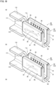
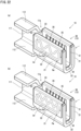
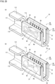
- the welded portion Pw may form one or a plurality of endless welding patterns. That is, as illustrated in Figs. 19(a) to 24(a) , the pattern is a totally or partially closed pattern (closed loop pattern) in which the start point Ps and the end point Pe of the welding line Lw are connected to the same welding line Lw. In each drawing, the directions in which the welding machine moves are indicated by arrows. In addition, all or a part of the welded portion Pw and the welding line Lw may be formed by so-called wobbling welding in which scanning is performed while drawing a fine pattern such as a circle or a line.
- the welding line Lw may have an elliptical shape or an oval shape.
- a shape having a triangle, a square, or more corners may also be adopted.
- a shape in which the letter "8" is connected once, twice, or more times may also be adopted.
- a shape in which a curved line or a folding line is drawn, and both end portions is connected to each other may also be adopted.
- a shape in which the long side portions of an elliptical shape is brought close to each other may be adopted, or as illustrated in Fig. 23(b) , a shape in which a circle or the like (including an elliptical shape, a polygonal shape, or the like) is drawn at the start point Ps and the end point Pe to connect both end portions to a middle portion of the welding line Lw may be adopted. Further, as illustrated in Fig.
- a shape in which both end portions is connected to a middle portion of the welding line Lw by continuously drawing a circle or the like (including an elliptical shape, a polygonal shape, or the like) while moving to one side may be adopted.
- the welding pattern illustrated in Figs. 19(a) to 23(a) is formed such that the end point Pe of the continuous welding line Lw is disposed at the start point Ps of the welding line Lw.
- the coordinates of the start point Ps and the coordinates of the end point Pe of the welding line Lw coincide with each other.
- the welding machine when welding is performed from the start point Ps to the end point Pe of the welding line Lw, the welding machine returns to the same position, and thus, the lead time in the welding process can be shortened.
- the female terminal 10 is sent to the welding machine one after another, and it is necessary to weld the base portion 20 of the female terminal 10 and the spring member 30 sequentially, but the end point Pe of the welding process for one female terminal 10 and the start point Ps of the welding process for the next female terminal 10 are the same, and it is not necessary to move the welding machine, which can shorten the lead time in the welding process.
- the continuous welding line Lw passes through the start point Ps of the welding line Lw, and the end point Pe of the welding line Lw is disposed in a middle portion of the welding line Lw.
- the coordinates of the start point Ps of the welding line Lw and the coordinates of the middle portion at one time point coincide with each other, and the coordinates of the middle portion at one time point coincide with the coordinates of the end point Pe.
- the length of the welding line Lw is relatively shortened while a closed pattern is formed, and thus, the lead time in the welding process can be shortened.
- the length of the welding line Lw is relatively short, and the welding machine can be moved at a relatively fast speed from the end point Pe of the welding process for one female terminal 10 to the start point Ps of the welding process for the next female terminal 10, which can shorten the lead time in the welding process.
- the invention of the present application includes the connector 1 (see Fig. 1 ) provided with the female terminal 10 and the connector housing 4 that houses the female terminal 10, and the terminal-attached electric wire 6 (see Fig. 1 ) provided with the female terminal 10 and the electric wire 3 connected to the base portion 20 of the female terminal 10.
- the invention of the present application includes the connector-attached electric wire 7 (see Fig. 1 ) provided with the terminal-attached electric wire 6 and the connector housing 4 that houses the terminal-attached electric wire 6, and the wire harness 2 (see Fig. 1 ) provided with at least one of the terminal-attached electric wire 6 and the connector-attached electric wire 7.
Landscapes
- Connections Effected By Soldering, Adhesion, Or Permanent Deformation (AREA)
Abstract
Description
- The present invention relates to a female terminal of an electric circuit through which a large current flows, a connector, a terminal-attached electric wire, a connector-attached electric wire, and a wire harness.
- An electric device conventionally constitutes an electric circuit by connecting an electric device and a power supply device with a wire harness. The wire harness and the electric device as well as the wire harness and the power supply device are connected to each other via connectors attached to the respective devices.
- For example, in the connector disclosed in
Patent Literature 1, a female terminal is housed in a connector housing. In such a female terminal, a terminal body is formed of a base portion and a spring member, and when a male terminal is inserted, an arm spring that is a part of the spring member deform to bend. - Patent Literature 1:
JP 2009-245701 A - Meanwhile, since a large current flows in an electric circuit such as a drive system in an automobile, it is conceivable to weld a base portion and a spring member to ensure favorable conductivity. However, not only when the arm spring greatly deforms, but also when the spring member is formed of a thick base material for improving conductivity, flexibility of the arm spring is reduced, and thus there is a possibility that an excessive load acts on a welded portion between the base portion and the spring member.
- An object of the present invention is to provide a female terminal, a connector, a terminal-attached electric wire, a connector-attached electric wire, and a wire harness capable of preventing an excessive load from acting on a welded portion between a base portion and a spring member.
- The present invention is a female terminal including a terminal body, the terminal body including a base portion to be connected to an electric wire, and a spring member that is attached to the base portion, in which the base portion includes a pair of side walls disposed at a predetermined interval into which a male terminal can be inserted, the spring member includes a laying plate along at least an inner side surface of each of the side walls and an arm spring extending from the laying plate toward the side wall facing the laying plate, the side wall and the laying plate are welded to form a welded portion, and a fulcrum portion of the arm spring abutting the side wall is provided between the welded portion and a contact portion of the arm spring.
- The contact portion in the present invention refers to a portion at a distal end of the arm spring, the portion abutting a male terminal in a state where the male terminal is inserted inside the female terminal. The fulcrum portion in the present invention refers to a portion at a proximal end of the arm spring, the portion abutting a side wall in a state where a male terminal is inserted at least inside the female terminal. Further, the term "between the welded portion and the contact portion of the arm spring" in the present invention refers to a range sandwiched between the welded portion and the contact portion in a state where the spring member formed by bending the base material is developed in a flat plate shape.
- The present invention also includes a connector including the female terminal and a connector housing that houses the female terminal, and a terminal-attached electric wire including the female terminal and the electric wire connected to the base portion of the female terminal.
- The present invention further includes a connector-attached electric wire including the terminal-attached electric wire and a connector housing that houses the terminal-attached electric wire, and a wire harness including at least one of the terminal-attached electric wire and the connector-attached electric wire.
- The present invention can prevent an excessive load from acting on the welded portion between the base portion and the spring member.
- More specifically, in the female terminal and the like according to the present invention, a fulcrum portion of the arm spring abutting the side wall is provided between the welded portion and the contact portion of the arm spring. According to such a configuration, even when the contact portion is pushed by the insertion of the male terminal, the fulcrum portion is not displaced in a state of abutting the side wall, and thus the arm spring deforms on the contact portion side from the fulcrum portion, which suppresses the deformation of the laying plate on the welded portion side from the fulcrum portion. Thus, it is possible to prevent an excessive load from acting on the welded portion between the side wall and the laying plate. In other words, it is possible to prevent an excessive load from acting on the welded portion between the base portion and the spring member.
- In addition, since the fulcrum portion reliably abuts the side wall of the base portion, a current flows through a short path. That is, when a current flows from the male terminal to the female terminal, the current flows from the contact portion abutting the male terminal to the side wall via the arm spring and through the fulcrum portion. When a current flows from the female terminal to the male terminal, the current flows from the fulcrum portion abutting the side wall to the male terminal via the arm spring and through the contact portion. Thus, electric resistance at these terminals can be held low. Such a structure can be said to be a structure particularly suitable for an electric circuit through which a large current flows.
- As an aspect of the present invention, the laying plate may be disposed along a distal end surface of the side wall, and the laying plate may be welded to the distal end surface of the side wall.
- The distal end surface in the present invention refers to a surface intersecting an insertion direction of the male terminal in at least one side wall of the pair of side walls. The laying plate in the present invention is a part of the spring member disposed along the distal end surface of the side wall so as to cover the distal end surface of the side wall, and it corresponds to a flange plate to be described later.
- According to the present invention, even when the contact portion is pushed by the insertion of the male terminal, the fulcrum portion is not displaced in a state of abutting the side wall, and thus the arm spring deforms on the contact portion side from the fulcrum portion, which suppresses the deformation of the laying plate on the welded portion side from the fulcrum portion. In addition, even when a load acts on the laying plate along the inner side surface of the side wall due to the moment about the fulcrum portion, the load does not affect the laying plate along the distal end surface of the side wall. Thus, it is possible to prevent an excessive load from acting on the welded portion between the side wall and the laying plate. In other words, it is possible to prevent an excessive load from acting on the welded portion between the base portion and the spring member.
- In addition, since the distal end surface of the side wall and the laying plate along the distal end surface are surfaces intersecting with the insertion direction of the male terminal, the welding machine that performs these welding can freely approach and move. Thus, such a welding step can be easily realized. In this regard, the portion where the laying plate overlaps the distal end surface of the side wall has a shape having a narrow width and a long length, and thus it is preferable to perform linear or dotted welding.
- As an aspect of the present invention, the laying plate may be disposed along an outer side surface of the side wall, and the laying plate may be welded to the outer side surface of the side wall.
- The outer side surface in the present invention refers to a surface of at least one side wall of the pair of side walls, the surface being on the opposite side of the surface facing a side surface of the male terminal. The laying plate in the present invention is a part of the spring member disposed along the outer side surface of the side wall so as to cover the outer side surface of the side wall, and it corresponds to an outer plate to be described later.
- According to the present invention, even when the contact portion is pushed by the insertion of the male terminal, the fulcrum portion is not displaced in a state of abutting the side wall, and thus the arm spring deforms on the contact portion side from the fulcrum portion, which suppresses the deformation of the laying plate on the welded portion side from the fulcrum portion. In addition, even when a load acts on the laying plate along the inner side surface of the side wall due to the moment about the fulcrum portion, the load does not affect the laying plate along the outer side surface of the side wall. Thus, it is possible to prevent an excessive load from acting on the welded portion between the side wall and the laying plate. In other words, it is possible to prevent an excessive load from acting on the welded portion between the base portion and the spring member.
- In addition, since the outer side surface of the side wall and the laying plate along the outer side surface are surfaces on the opposite side of the surface facing a side surface of the inserted male terminal, the welding machine that performs these welding can freely approach and move. Thus, such a welding step can be easily realized. In this regard, the portion where the laying plate overlaps the outer side surface of the side wall has a shape having a wide width and a long length, and thus any welding mode can be applied.
- As an aspect of the present invention, the laying plate may be disposed along an inner side surface of the side wall, and the laying plate may be welded to the inner side surface of the side wall.
- The inner side surface in the present invention refers to a surface of at least one side wall of the pair of side walls, the surface facing a side surface of the male terminal. The laying plate in the present invention is a part of the spring member disposed along the inner side surface of the side wall so as to cover the inner side surface of the side wall, and it corresponds to an inner plate to be described later.
- According to the present invention, even when the contact portion is pushed by the insertion of the male terminal, the fulcrum portion is not displaced in a state of abutting the side wall, and thus the arm spring deforms on the contact portion side from the fulcrum portion, which suppresses the deformation of the laying plate on the welded portion side from the fulcrum portion. In addition, since the laying plate is welded to the inner side surface of the side wall, deformation of the laying plate can be suppressed by devising the welding mode. Thus, it is possible to prevent an excessive load from acting on the welded portion between the side wall and the laying plate. In other words, it is possible to prevent an excessive load from acting on the welded portion between the base portion and the spring member.
- As an aspect of the present invention, the welded portion in at least one side wall of the pair of side walls may include a plurality of welded portions or a plurality of welded points.
- The plurality of welded points in the present invention refer to a plurality of linear or curved welded points. However, these welded points are not limited to welded points being parallel to each other. The plurality of welded points in the present invention refer to a plurality of welded points having a solid line shape, a dotted line shape, or a point group shape. However, the shape of each welded point is not limited.
- The present invention can prevent a load from concentrating on a specific welded portion. In addition, even when a load is concentrated on a specific welded portion and the welded portion is broken or the like, it is possible to prevent the welded portion from being broken or the like as a whole. Thus, conductivity can be stabilized. Further, a parallel circuit is configured locally because a current flows through corresponding welded portions. Thus, electric resistance at these terminals can be held low. Such a structure can also be said to be a structure particularly suitable for an electric circuit through which a large current flows.
- As an aspect of the present invention, the fulcrum portion of the arm spring may be a portion that abuts a protruding portion provided on the laying plate and protruding toward the side wall or a protruding portion provided on the side wall and protruding toward the laying plate.
- In the present invention, the protruding portion refers to a portion that locally protrudes due to bending or formation of a raised portion when provided on the laying plate. It refers to a portion that locally protrudes due to bending or formation of a raised portion also when provided on the side wall. However, a cross-sectional shape of the portion is not limited to an arc shape.
- According to this invention, when the protruding portion is provided on the laying plate, the vertex of the protruding portion reliably abuts the side wall. When the protruding portion is provided on the side wall, the vertex of the protruding portion reliably abuts the laying plate. Thus, it is possible to prevent the fulcrum portion from being displaced when the male terminal is inserted into the female terminal.
- As an aspect of the present invention, the welded portion in at least one side wall of the pair of side walls may form one or a plurality of curved or bent-line-shaped welding patterns.
- The curved or bent-line-shaped welding pattern in the present invention refers to a pattern having one or more curved points or bending points. However, a specific aspect of the pattern having one or more curved points or bending points is not limited.
- According to the present invention, since the length of the welding line increases, the strength against a load can improve. In addition, conductivity can improve. Such a structure can also be said to be a structure particularly suitable for an electric circuit through which a large current flows. Further, since the load acts in a distributed manner for each section in the welding line, it is possible to prevent the welded portion from being broken or the like as a whole even when the load concentrates on a specific section and the welded portion is broken or the like. Thus, conductivity can also be stabilized.
- As an aspect of the present invention, the welded portion in at least one side wall of the pair of side walls may form a welding pattern with an end in which one or a plurality of end portions are widened.
- The welding pattern with an end in the present invention refers to an open pattern in which a start point and an end point of a welding line are not connected to the same welding line and do not intersect at a middle portion of the welding line. However, a specific aspect of the open pattern is not limited.
- According to this invention, since the start point and the end point of the welding line are wider than other portions of the welding line, the strength of the start point and the end point against the load can be improved. Thus, it is possible to prevent occurrence of damage such as cracking or peeling at the start point of the welding line. It is also possible to prevent occurrence of damage such as cracking or peeling at the end point of the welding line. Although the start point and the end point are widened, they can be formed in a straight line shape, and thus can be applied to a narrow region of the laying plate.
- As an aspect of the present invention, the welded portion in at least one side wall of the pair of side walls may form one or a plurality of endless welding patterns.
- The endless welding pattern in the present invention refers to a totally or partially closed pattern (closed loop pattern) formed by connecting a start point and an end point of a welding line to the same welding line. However, the present invention is not limited to a specific aspect of the totally closed pattern and the partially closed pattern.
- According to the present invention, since the start point and the end point of the welding line do not appear as end portions of the welding line, it is possible to prevent an excessive load (including fatigue due to repeated stress) from acting on these start point and end point. Thus, it is possible to prevent occurrence of damage such as cracking or peeling at the start point of the welding line. It is also possible to prevent occurrence of damage such as cracking or peeling at the end point of the welding line. Since the welding line has a totally or partially closed pattern, the fatigue strength can be improved even against vibration from any direction.
- As an aspect of the present invention, the welding pattern may be formed by disposing an end point of a continuous welding line at a start point of the welding line.
- The continuous welding line in the present invention refers to a solid welding line. In the present invention, disposing an end point of a continuous welding line at a start point of the welding line means that the coordinates of the start point of the welding line coincide with the coordinates of the end point. However, it is sufficient that the welding line (so-called bead) has a totally or partially closed pattern, and the coordinates are not limited to complete matching.
- According to this invention, when welding is performed from the start point to the end point of the welding line, the welding machine returns to the same position, and thus, the lead time in the welding process can be shortened. Specifically, the female terminal is sent to the welding machine one after another, and it is necessary to weld the base portion of the female terminal and the spring member sequentially, but the end point of the welding process for one female terminal and the start point of the welding process for the next female terminal are the same, and it is not necessary to move the welding machine, which can shorten the lead time in the welding process.
- As an aspect of the present invention, the welding pattern may be formed such that a continuous welding line passes through a start point of the welding line, and an end point of the welding line may be disposed in a middle portion of the welding line.
- The continuous welding line in the present invention also refers to a solid welding line. In the present invention, a welding line passing through a start point of the welding line means that the coordinates of the start point of the welding line coincide with the coordinates at one time point in the middle portion, and an end point of the welding line being disposed in a middle portion of the welding line means that the coordinates at one time point in the middle portion of the welding line coincide with the coordinates at the end point. However, as in the above description, the coordinates are not limited to complete matching.
- According to the present invention, the length of the welding line is relatively shortened while a closed pattern is formed, and thus, the lead time in the welding process can be shortened. Specifically, although it is necessary to move the welding machine at a relatively slow speed from the start point to the end point of the welding line, the length of the welding line is relatively short, and the welding machine can be moved at a relatively fast speed from the end point of the welding process for one female terminal to the start point of the welding process for the next female terminal, which can shorten the lead time in the welding process.
-
-
Fig. 1 is an overall perspective view illustrating a connector. -
Fig. 2 is an exploded perspective view of a female terminal. -
Fig. 3 is a perspective view of the female terminal. -
Fig. 4 is a side view of the female terminal. -
Fig. 5 is a front view of the female terminal. -
Fig. 6 is a plan view of the female terminal. -
Fig. 7 is a cross-sectional view as viewed from the arrow A-A inFig. 6 . -
Fig. 8 includes a cross-sectional view as viewed from the arrow B-B and a cross-sectional view as viewed from the arrow C-C inFig. 6 . -
Fig. 9 is an enlarged cross-sectional view of the female terminal. -
Fig. 10 is an enlarged cross-sectional view of a state in which a male terminal is inserted inside the female terminal. -
Fig. 11 is an assembly explanatory view of the female terminal. -
Fig. 12 is a cross-sectional view of a female terminal according to another embodiment. -
Fig. 13 is a cross-sectional view of a female terminal according to another embodiment. -
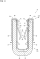
Fig. 14 is a cross-sectional view of a female terminal according to another embodiment. -
Fig. 15 is a cross-sectional view of a female terminal according to another embodiment. -
Fig. 16 is a cross-sectional view of a female terminal according to another embodiment. -
Fig. 17 is a cross-sectional view of a female terminal according to another embodiment. -
Fig. 18 is a cross-sectional view of a female terminal according to another embodiment. -
Fig. 19 is a cross-sectional view of a female terminal according to another embodiment. -
Fig. 20 is a cross-sectional view of a female terminal according to another embodiment. -
Fig. 21 is a cross-sectional view of a female terminal according to another embodiment. -
Fig. 22 is a cross-sectional view of a female terminal according to another embodiment. -
Fig. 23 is a cross-sectional view of a female terminal according to another embodiment. -
Fig. 24 is a cross-sectional view of a female terminal according to another embodiment. - An embodiment of the present invention will be described in detail with reference to the drawings.
-
Fig. 1 is an overall perspective view illustrating aconnector 1. InFig. 1 , aconnector housing 4 that houses afemale terminal 10 is indicated by a broken line. -
Fig. 2 is an exploded perspective view of thefemale terminal 10.Fig. 3 is a perspective view of thefemale terminal 10.Fig. 4 is a side view of thefemale terminal 10,Fig. 5 is a front view of thefemale terminal 10, andFig. 6 is a plan view of thefemale terminal 10.Fig. 7 is a cross-sectional view as viewed from the arrow A-A inFig. 6 , andFig. 8 includes a cross-sectional view as viewed from the arrow B-B and a cross-sectional view as viewed from the arrow C-C inFig. 6 .Fig. 9 is an enlarged cross-sectional view of thefemale terminal 10, andFig. 10 is an enlarged cross-sectional view of a state in which amale terminal 5 is inserted inside thefemale terminal 10.Fig. 11 is an assembly explanatory view of thefemale terminal 10. - As illustrated in
Fig. 1 , theconnector 1 is attached to a distal end of anelectric wire 3 constituting awire harness 2. In theconnector 1, twofemale terminals 10 are housed in theconnector housing 4 in parallel. - The
wire harness 2 is configured by bundling a plurality ofelectric wires 3. Theelectric wire 3 is formed by covering acore wire 3a which is an electric conductor with an insulatingcover 3b, and thecore wire 3a exposed at a distal end of theelectric wire 3 is connected to abase portion 20 of thefemale terminal 10. - The
connector housing 4 includes an electricwire insertion portion 41 through which theelectric wire 3 is inserted and aterminal housing portion 42 that houses thefemale terminal 10. Ahousing space 4S in which thefemale terminal 10 is housed is open in a substantially quadrangular shape, and a protruding portion of the connector housing that houses the male terminal 5 (seeFig. 9 ) is fitted into the opening. At this time, themale terminal 5 is inserted into thefemale terminal 10, and the terminals are electrically connected to each other. - As illustrated in
Figs. 2 to 10 , thefemale terminal 10 includes an electricwire connection portion 11 and aterminal connection portion 12. The electricwire connection portion 11 and theterminal connection portion 12 are provided in series on an extension line of theelectric wire 3. In the present application, such a direction will be described as a longitudinal direction L. A direction parallel to the direction in which the male terminal 5 (seeFig. 10 ) is inserted is referred to as a height direction H, and a direction orthogonal to the longitudinal direction L and the height direction H is referred to as a width direction W. - The electric
wire connection portion 11 is provided with aconnection plate 111 perpendicular to the width direction W. An upper end and a lower end of theconnection plate 111 are bent to provideguide pieces 112. Each of theguide pieces 112 has a role of suppressing expansion of thecore wires 3a connected to theconnection plate 111. - The
terminal connection portion 12 is provided with aterminal body 13 to be electrically connected to themale terminal 5. In thefemale terminal 10 according to the present embodiment, theterminal body 13 includes abase portion 20 integrally formed including the electricwire connection portion 11 and aspring member 30 to be attached to thebase portion 20. Hereinafter, thebase portion 20 and thespring member 30 will be described in detail. - The
base portion 20 has a pair ofside walls 21 disposed at a predetermined interval into which themale terminal 5 can be inserted. More specifically, thebase portion 20 has a pair ofside walls 21 separated by a predetermined interval perpendicular to the width direction W. Thebase portion 20 has abottom wall 22 that connects lower ends of therespective side walls 21. Thus, thebase portion 20 has a substantially U shape as viewed in the longitudinal direction L (seeFig. 4 ). - The
side wall 21 on one side of thebase portion 20 is formed by extending theconnection plate 111 in the longitudinal direction L. Theside wall 21 on the other side is formed by folding back a plate material (base material of the base portion 20) to the side where theguide pieces 112 are formed. Thus, thebase portion 20 has a substantially rectangular shape as viewed in the height direction H (seeFig. 6 ). In this manner, thebase portion 20 achieves downsizing of thefemale terminal 10 by forming theside wall 21 on the other side on the side where theguide pieces 112 are formed. - Further, the
guide piece 112 on the upper side of thebase portion 20 is formed by bending the upper end of theconnection plate 111 and is provided with acutout portion 11a so that theside wall 21 is not distorted when theguide piece 112 is formed. In the same manner, theguide piece 112 on the lower side of thebase portion 20 is formed by bending the lower end of theconnection plate 111 and is provided with acutout portion 11b so that theside wall 21 is not distorted when theguide piece 112 is formed. A part of thespring member 30 is exposed at thecutout portion 11b, and thespring member 30 can be pushed out and removed from the lower side (seeFig. 5 ). - The
base portion 20 is formed by being cut out from a plate material having conductivity such as a copper alloy or an aluminum alloy and being bent. Thebase portion 20 is not plated on its surface, but thebase portion 20 is not limited to this configuration. Thus, the surface may be subjected to plating treatment such as silver plating or tin plating for improving conductivity. Alternatively, plating may be partially performed. For example, one in which one surface of the electricwire connection portion 11 or theterminal connection portion 12 is plated can be considered as the base portion in which the plating treatment is partially performed. Alternatively, only the electricwire connection portion 11 may be plated, or only theterminal connection portion 12 may be plated. - The
spring member 30 has aninner plate 31 along theinner side surface 21a of theside wall 21 in a state of being fitted between the pair ofside walls 21. Thespring member 30 also has anouter plate 32 along theouter side surface 21b of theside wall 21. Further, thespring member 30 has aflange plate 33 that connects upper ends of theinner plate 31 and theouter plate 32. Thespring member 30 has abottom plate 34 connecting lower ends of the respectiveinner plates 31. Thus, thespring member 30 has a substantially M shape as viewed in the longitudinal direction L (seeFig. 4 ). - The
inner plate 31 on one side of thespring member 30 extends in the longitudinal direction L along the opening end edge of theside wall 21, and six arm springs 35 extend from theinner plate 31 toward the opposing side wall 21 (seeFig. 7 ). All the arm springs 35 have the same shape, and specifically, they extend obliquely downward so as to approach the opposingside wall 21 as viewed in the longitudinal direction L and have a shape in which a part including a distal end edge thereof is folded back (seeFig. 8 ). - The
arm spring 35 provided on theinner plate 31 on one side extends from the lower end edge of theinner plate 31 along the opening end edge of theside wall 21, and a boundary portion with theinner plate 31 serves as a fulcrum portion Pp (seeFig. 8 ). In thefemale terminal 10, the fulcrum portion Pp always abuts theinner side surface 21a of theside wall 21. However, the fulcrum portion Pp may abut with deformation when themale terminal 5 is inserted into thefemale terminal 10. - Further, the
inner plate 31 on the other side of thespring member 30 also extends in the longitudinal direction L along the opening end edge of theside wall 21, and six arm springs 35 extend from theinner plate 31 toward the opposing side wall 21 (seeFig. 7 ). All the arm springs 35 have the same shape, and specifically, they extend obliquely downward so as to approach the opposingside wall 21 as viewed in the longitudinal direction L and have a shape in which a part including a distal end edge thereof is folded back (seeFig. 8 ). - The
arm spring 35 provided on theinner plate 31 on the other side also extends from the lower end edge of theinner plate 31 along the opening end edge of theside wall 21, and a boundary portion with theinner plate 31 serves as a fulcrum portion Pp (seeFig. 8 ). In thefemale terminal 10, the fulcrum portion Pp always abuts theinner side surface 21a of theside wall 21. However, the fulcrum portion Pp may abut with deformation when themale terminal 5 is inserted into thefemale terminal 10. - In addition, in the
spring member 30, theflange plate 33 is in surface contact with adistal end surface 21c of theside wall 21. Welding is performed along the longitudinal direction L in the area in surface contact. Thus, a linear welded portion Pw is formed on the flange plate 33 (seeFigs. 6 to 9 ). The welded portion Pw is a portion where a part of theside wall 21 or theflange plate 33 is melted, cooled, and solidified again. A center line C of the welded portion Pw is perpendicular to thedistal end surface 21c of theside wall 21 and theflange plate 33. - Further, in the
female terminal 10 according to the present embodiment, the fulcrum portion Pp is provided between the welded portion Pw and a contact portion Pc of the arm spring 35 (see a range R inFig. 9 ). Specifically, in a state where thespring member 30 formed by bending the base material is developed in a flat plate shape, the fulcrum portion Pp is provided in the range R sandwiched between the welded portion Pw and the contact portion Pc. According to such a configuration, even when the contact portion Pc is pushed by the insertion of the male terminal 5 (see the arrow Fi inFig. 10 ), the fulcrum portion Pp is not displaced in a state of abutting theside wall 21, and thus thearm spring 35 deforms on the contact portion Pc side from the fulcrum portion Pp (see the two dot chain line D inFig. 10 ), which suppresses the deformation of theinner plate 31 on the welded portion Pw side from the fulcrum portion Pp. - In addition, in the
female terminal 10 according to the present embodiment, a relationship of L1 < L2 is preferably established where L1 is a length from thedistal end surface 21c of theside wall 21 to the fulcrum portion Pp of thearm spring 35, and L2 is a length from the fulcrum portion Pp of thearm spring 35 to the contact portion Pc. According to such a configuration, when a load (see the arrow Fi inFig. 10 ) is applied to the contact portion Pc of thearm spring 35, a rotational force about the fulcrum portion Pp is generated, and even when a load (see the arrow Fr inFig. 10 ) that rises from theinner side surface 21a acts on theinner plate 31 closer to the welded portion Pw than the fulcrum portion Pp, the load does not affect theflange plate 33 perpendicular to theinner plate 31. That is, it is considered that theflange plate 33 does not deform to rise from thedistal end surface 21c. - In addition, in the
female terminal 10 according to the present embodiment, the fulcrum portion Pp serves a function of electrically connecting thearm spring 35 and theside wall 21. Thus, when a current flows from themale terminal 5 to thefemale terminal 10, the current flows from the contact portion Pc abutting themale terminal 5 to theside wall 21 via thearm spring 35 and through the fulcrum portion Pp (see the arrows A inFig. 10 ). When a current flows from thefemale terminal 10 to themale terminal 5, the current flows from the fulcrum portion Pp abutting theside wall 21 to themale terminal 5 via thearm spring 35 and through the contact portion Pc (see the arrows A inFig. 10 ). In this regard, even when the conductivity at the fulcrum portion Pp is low, a current flows through the welded portion Pw close to the fulcrum portion Pp. - The
female terminal 10 is assembled as follows. That is, as illustrated inFig. 11 , thespring member 30 is disposed on the upper side of thebase portion 20, theinner plate 31 and thebottom plate 34 are fitted between the pair ofside walls 21, and welding is performed to assemble thefemale terminal 10 in a state where theflange plate 33 is brought into surface contact with thedistal end surface 21c of theside wall 21. Thefemale terminal 10 is configured such that a relationship of d ≤ D is established where d is a width dimension from the opening end edge of theside wall 21 on one side to the opening end edge of theside wall 21 on the other side, and D is a width dimension from the opening end edge of theinner plate 31 on one side to the opening end edge of theinner plate 31 on the other side. In addition, thefemale terminal 10 is configured such that a relationship of h ≥ H is established where h is a height dimension from the inner side surface of thebottom wall 22 to thedistal end surface 21c of theside wall 21, and H is a height dimension from thebottom plate 34 to theflange plate 33. Thus, backlash of thespring member 30 can be suppressed, a wide contact area can be secured, and theflange plate 33 can be reliably brought into surface contact with thedistal end surface 21c of theside wall 21. - Next, the
female terminal 10 according to another embodiment will be described with reference toFig. 12 . In thefemale terminal 10, theouter plate 32 is welded to theouter side surface 21b of theside wall 21. The fulcrum portion Pp is provided between the welded portion Pw and the contact portion Pc of the arm spring 35 (see the range R inFig. 12 ). Further, it is preferable that a relationship of L1 < L2 is established where L1 is a length from the center line C of the welded portion Pw to the fulcrum portion Pp of thearm spring 35, and L2 is a length from the fulcrum portion Pp of thearm spring 35 to the contact portion Pc. - According to such a
female terminal 10, a rotational force about the fulcrum portion Pp is generated by applying a load to the contact portion Pc of thearm spring 35, and even when a load that rises from theinner side surface 21a acts on theinner plate 31 closer to the welded portion Pw than the fulcrum portion Pp, the load does not affect theouter plate 32 parallel to theinner plate 31. That is, it is considered that theouter plate 32 does not deform to rise from theouter side surface 21b. - Next, the
female terminal 10 according to another embodiment will be described with reference toFig. 13 . In thefemale terminal 10, theinner plate 31 is welded to theinner side surface 21a of theside wall 21. The fulcrum portion Pp is provided between the welded portion Pw and the contact portion Pc of the arm spring 35 (see the range R inFig. 13 ). Further, it is preferable that a relationship of L1 < L2 is established where L1 is a length from the center line C of the welded portion Pw to the fulcrum portion Pp of thearm spring 35, and L2 is a length from the fulcrum portion Pp of thearm spring 35 to the contact portion Pc. - According to such a
female terminal 10, a rotational force about the fulcrum portion Pp is generated by applying a load to the contact portion Pc of thearm spring 35, and even when a load that rises from theinner side surface 21a acts on theinner plate 31 closer to the welded portion Pw than the fulcrum portion Pp, deformation of theinner plate 31 can be suppressed by devising a welding more. For example, in theinner plate 31 along each of the pair ofside walls 21, it is considered that deformation of theinner plate 31 can be suppressed by configuring each welded portion Pw with a plurality of welded portions Pw or a plurality of welded points. - In this manner, in the
female terminal 10 according to the present embodiment, theterminal body 13 is provided by thebase portion 20 to be connected to theelectric wire 3 and thespring member 30 to be attached to thebase portion 20. Thebase portion 20 has the pair ofside walls 21 disposed at a predetermined interval into which themale terminal 5 can be inserted, thespring member 30 has the laying plate (inner plate 31) along theinner side surface 21a of theside wall 21 and thearm spring 35 extending from the laying plate (inner plate 31) toward the opposingside wall 21, and theside wall 21 and the laying plate (for example, the flange plate 33) are welded to form the welded portion Pw. The present embodiment is characterized in that the fulcrum portion Pp of thearm spring 35 abutting theside wall 21 is provided between the welded portion Pw and the contact portion Pc of thearm spring 35. - According to such a
female terminal 10, it is possible to prevent an excessive load from acting on the welded portion Pw between thebase portion 20 and thespring member 30. - More specifically, in the
female terminal 10 according to the present invention, the fulcrum portion Pp of thearm spring 35 abutting theside wall 21 is provided between the welded portion Pw and the contact portion Pc of thearm spring 35. According to such a configuration, even when the contact portion Pc is pushed by the insertion of the male terminal 5 (see the arrow Fi inFig. 10 ), the fulcrum portion Pp is not displaced in a state of abutting theside wall 21, and thus thearm spring 35 deforms on the contact portion Pc side from the fulcrum portion Pp (see the two dot chain line D inFig. 10 ), which suppresses the deformation of theinner plate 31 on the welded portion Pw side from the fulcrum portion Pp. Thus, it is possible to prevent an excessive load from acting on the welded portion Pw between theside wall 21 and theflange plate 33. In other words, it is possible to prevent an excessive load from acting on the welded portion Pw between thebase portion 20 and thespring member 30. - In addition, since the fulcrum portion Pp reliably abuts the
side wall 21 of thebase portion 20, a current flows through a short path. That is, when a current flows from themale terminal 5 to thefemale terminal 10, the current flows from the contact portion Pc abutting themale terminal 5 to theside wall 21 via thearm spring 35 and through the fulcrum portion Pp (see the arrows A inFig. 10 ). When a current flows from thefemale terminal 10 to themale terminal 5, the current flows from the fulcrum portion Pp abutting theside wall 21 to themale terminal 5 via thearm spring 35 and through the contact portion Pc (see the arrows A inFig. 10 ). Thus, electric resistance at these terminals can be held low. Such a structure can be said to be a structure particularly suitable for an electric circuit through which a large current flows. - In the
female terminal 10 according to the first embodiment, theflange plate 33 is provided along thedistal end surface 21c of theside wall 21, and theflange plate 33 is welded to thedistal end surface 21c of theside wall 21. Thedistal end surface 21c is a surface of at least oneside wall 21 of the pair ofside walls 21 intersecting the insertion direction of themale terminal 5. - According to such a
female terminal 10, even when the contact portion Pc is pushed by the insertion of themale terminal 5, the fulcrum portion Pp is not displaced in a state of abutting theside wall 21, and thus thearm spring 35 deforms on the contact portion Pc side from the fulcrum portion Pp, which suppresses the deformation of theinner plate 31 on the welded portion Pw side of the fulcrum portion Pp. In addition, even when a load acts on theinner side surface 21a of theside wall 21 due to the moment about the fulcrum portion Pp, the load does not affect theflange plate 33 along thedistal end surface 21c of theside wall 21. Thus, it is possible to prevent an excessive load from acting on the welded portion between theside wall 21 and theflange plate 33. In other words, it is possible to prevent an excessive load from acting on the welded portion Pw between thebase portion 20 and thespring member 30. - In addition, even when the conductivity at the fulcrum portion Pp is low, a current flows through a relatively short path. That is, when a current flows from the
male terminal 5 to thefemale terminal 10, the current flows from the contact portion Pc abutting themale terminal 5 to theside wall 21 via thearm spring 35, not through the fulcrum portion Pp but through the welded portion Pw formed on theflange plate 33 along thedistal end surface 21c of theside wall 21. On the other hand, when a current flows from thefemale terminal 10 to themale terminal 5, the current flows not from the fulcrum portion Pp abutting theside wall 21 but from the welded portion Pw formed on theflange plate 33 along thedistal end surface 21c of theside wall 21 to themale terminal 5 via thearm spring 35 and through the contact portion Pc. Thus, electric resistance at these terminals can be held low. Such a structure can also be said to be a structure particularly suitable for an electric circuit through which a large current flows. - In addition, since the
distal end surface 21c of theside wall 21 and theflange plate 33 along thedistal end surface 21c are surfaces intersecting with the insertion direction of themale terminal 5, the welding machine that performs these welding can freely approach and move. Thus, such a welding step can be easily realized. In this regard, the portion where theflange plate 33 overlaps thedistal end surface 21c of theside wall 21 has a shape having a narrow width and a long length, and thus it is preferable to perform linear or dotted welding. - In the
female terminal 10 according to the second embodiment, theouter plate 32 is provided with respect to theouter side surface 21b of theside wall 21, and theouter plate 32 is welded to theouter side surface 21b of theside wall 21. Theouter side surface 21b is a surface of at least oneside wall 21 of the pair ofside walls 21, the surface being on the opposite side of the surface facing a side surface of themale terminal 5. - According to such a
female terminal 10, even when the contact portion Pc is pushed by the insertion of themale terminal 5, the fulcrum portion Pp is not displaced in a state of abutting theside wall 21, and thus thearm spring 35 deforms on the contact portion Pc side from the fulcrum portion Pp, which suppresses the deformation of theinner plate 31 on the welded portion Pw side of the fulcrum portion Pp. In addition, even when a load acts on theinner side surface 21a of theside wall 21 due to the moment about the fulcrum portion Pp, the load does not affect theouter plate 32 along theouter side surface 21b of theside wall 21. Thus, it is possible to prevent an excessive load from acting on the welded portion Pw between theside wall 21 and theouter plate 32. In other words, it is possible to prevent an excessive load from acting on the welded portion Pw between thebase portion 20 and thespring member 30. - In addition, even when the conductivity at the fulcrum portion Pp is low, a current flows through a relatively short path. That is, when a current flows from the
male terminal 5 to thefemale terminal 10, the current flows from the contact portion Pc abutting themale terminal 5 to theside wall 21 via thearm spring 35, not through the fulcrum portion Pp but through the welded portion Pw formed on theouter plate 32 along theouter side surface 21b of theside wall 21. When a current flows from thefemale terminal 10 to themale terminal 5, the current flows not from the fulcrum portion Pp abutting theside wall 21 but from the welded portion Pw formed on theouter plate 32 along theouter side surface 21b of theside wall 21 to themale terminal 5 via thearm spring 35 and through the contact portion Pc. Thus, electric resistance at these terminals can be held low. Such a structure can also be said to be a structure particularly suitable for an electric circuit through which a large current flows. - In addition, since the
outer side surface 21b of theside wall 21 and theouter plate 32 along theouter side surface 21b are surfaces on the opposite side of the surface facing a side surface of the insertedmale terminal 5, the welding machine that performs these welding can freely approach and move. Thus, such a welding step can be easily realized. In this regard, the portion where theouter plate 32 overlaps with respect to theouter side surface 21b of theside wall 21 has a shape having a wide width and a long length, and thus any welding mode can be applied. - In the
female terminal 10 according to a third embodiment, theinner plate 31 is provided along theinner side surface 21a of theside wall 21, and theinner plate 31 is welded to theinner side surface 21a of theside wall 21. Theinner side surface 21a is a surface of at least oneside wall 21 of the pair ofside walls 21 facing the side surface of themale terminal 5. - According to such a
female terminal 10, even when the contact portion Pc is pushed by the insertion of themale terminal 5, the fulcrum portion Pp is not displaced in a state of abutting theside wall 21, and thus thearm spring 35 deforms on the contact portion Pc side from the fulcrum portion Pp, which suppresses the deformation of theinner plate 31 on the welded portion Pw side of the fulcrum portion Pp. In addition, since theinner plate 31 is welded to theinner side surface 21a of theside wall 21, deformation of theinner plate 31 can be suppressed by devising a welding mode. Thus, it is possible to prevent an excessive load from acting on the welded portion Pw between theside wall 21 and theinner plate 31. In other words, it is possible to prevent an excessive load from acting on the welded portion Pw between thebase portion 20 and thespring member 30. - In addition, even when the conductivity at the fulcrum portion Pp is low, a current flows through a relatively short path. That is, when a current flows from the
male terminal 5 to thefemale terminal 10, the current flows from the contact portion Pc abutting themale terminal 5 to theside wall 21 via thearm spring 35, not through the fulcrum portion Pp but through the welded portion Pw formed on theinner plate 31 along theinner side surface 21a of theside wall 21. On the other hand, when a current flows from thefemale terminal 10 to themale terminal 5, the current flows not from the fulcrum portion Pp abutting theside wall 21 but from the welded portion Pw formed on theinner plate 31 along theinner side surface 21a of theside wall 21 to themale terminal 5 via thearm spring 35 and through the contact portion Pc. Thus, electric resistance at these terminals can be held low. Such a structure can also be said to be a structure particularly suitable for an electric circuit through which a large current flows. - In the
female terminal 10 according to each embodiment, theside wall 21 and the laying plate (inner plate 31,outer plate 32, and flange plate 33) are welded using a fiber laser welding machine, but welding may be performed by using an arc welding machine or the like. Welding may also be performed by using a welding machine capable of ultrasonic welding, resistance welding, friction welding, or other welding. Further, braze welding such as brazing and soldering is also included in the concept of welding. - In the correspondence between the configuration of the present invention and the foregoing embodiments, the connector of the present invention corresponds to the
connector 1, and - in the same manner,
- the wire harness corresponds to the
wire harness 2, - the electric wire corresponds to the
electric wire 3, - the connector housing corresponds to the
connector housing 4, - the male terminal corresponds to the
male terminal 5, - the female terminal corresponds to the
female terminal 10, - the terminal body corresponds to the
terminal body 13, - the base portion corresponds to the
base portion 20, - the side wall corresponds to the
side wall 21, - the inner side surface corresponds to the
inner side surface 21a, - the outer side surface corresponds to the
outer side surface 21b, - the distal end surface corresponds to the
distal end surface 21c, - the spring member corresponds to the
spring member 30, - the laying plate corresponds to the
inner plate 31, theouter plate 32, and theflange plate 33, - the arm spring corresponds to the
arm spring 35, - the welded portion corresponds to the welded portion Pw,
- the contact portion corresponds to the contact portion Pc, and
- the fulcrum portion corresponds to the fulcrum portion Pp. However, the present invention is not limited to the configuration of the foregoing embodiments, and many embodiments can be obtained.
- For example, in the
female terminal 10 according to the first embodiment, theflange plate 33 is welded to thedistal end surface 21c of theside wall 21, in thefemale terminal 10 according to the second embodiment, theouter plate 32 is welded to theouter side surface 21b of theside wall 21, and in thefemale terminal 10 according to the third embodiment, theinner plate 31 is welded to theinner side surface 21a of theside wall 21. However, as illustrated inFig. 14(a) , welding on theflange plate 33 and welding on theouter plate 32 may be performed. Alternatively, as illustrated inFig. 14(b) , welding on theflange plate 33 and welding on theinner plate 31 may be performed. Of course, as illustrated inFig. 14(c) , in theouter plate 32 along each of the pair ofside walls 21, each welded portion Pw may be configured by a plurality of welded portions Pw or a plurality of welded points. The same applies to the welded portions Pw of theinner plate 31 and theflange plate 33. - Having such a configuration can prevent a load from concentrating on a specific welded portion Pw. In addition, even when a load is concentrated on a specific welded portion Pw and the welded portion Pw is broken or the like, it is possible to prevent the welded portion Pw from being broken or the like as a whole. Thus, conductivity can be stabilized. Further, a parallel circuit is configured locally because a current flows through corresponding welded portions Pw. Thus, electric resistance at these terminals can be held low. Such a structure can also be said to be a structure particularly suitable for an electric circuit through which a large current flows.
- Further, in the
female terminal 10 according to each of the embodiments, thearm spring 35 extends from the lower end edge of theinner plate 31 along the opening end edge of theside wall 21, and a boundary portion with theinner plate 31 serves as the fulcrum portion Pp. However, as illustrated inFig. 15(a) , a protruding portion may be provided on theinner plate 31, and the vertex thereof may abut theside wall 21. Alternatively, as illustrated inFig. 15(b) , a protruding portion may be provided on theside wall 21, and the vertex thereof may abut theinner plate 31. - With such a configuration, when the protruding portion is provided on the
inner plate 31, the vertex of the protruding portion reliably abuts theside wall 21. On the other hand, when the protruding portion is provided on theside wall 21, the vertex of the protruding portion reliably abuts theinner plate 31. Thus, it is possible to prevent the fulcrum portion Pp from being displaced when themale terminal 5 is inserted into thefemale terminal 10. - In addition, in the
female terminal 10 according to each of the embodiments, the fulcrum portion Pp of thearm spring 35 is provided on theinner plate 31 along theinner side surface 21a of theside wall 21. However, as illustrated inFig. 16(a) , on the premise that the welded portion Pw is formed on theouter plate 32 or theflange plate 33, the fulcrum portion Pp may be provided at a bent portion that goes around a corner portion between theinner side surface 21a and thedistal end surface 21c of theside wall 21. Alternatively, as illustrated inFig. 16 (b) , on the premise that the welded portion Pw is formed on theouter plate 32, the fulcrum portion Pp may be provided at a bent portion that goes around a corner portion between theouter side surface 21b and thedistal end surface 21c of theside wall 21. - In addition, in the
female terminal 10 according to each of the embodiments, the welded portion Pw may form one or a plurality of curved or bent-line-shaped welding patterns. For example, as illustrated inFig. 17(a) , the welded portion Pw of theouter plate 32 may form a curved welding pattern. Alternatively, as illustrated inFig. 17(b) , the welded portion Pw of theouter plate 32 may form a bent-line-shaped welding pattern. - With such a configuration, since the length of the welding line Lw becomes long, the strength against the load can be improved. In addition, conductivity can improve. Such a structure can also be said to be a structure particularly suitable for an electric circuit through which a large current flows. Further, since the load acts in a distributed manner for each section in the welding line Lw, it is possible to prevent the welded portion Pw from being broken or the like as a whole even when the load concentrates on a specific section and the welded portion Pw is broken or the like. Thus, conductivity can also be stabilized.
- In addition, in the
female terminal 10 according to each of the embodiments, the welded portion Pw may form a welding pattern with an end in which one or a plurality of end portions are widened. For example, as illustrated inFig. 18(a) , both end portions may be formed in a widened shape by drawing a circle or the like (including a simple folding or wavy shape) at the start point Ps and the end point Pe. Alternatively, as illustrated inFig. 18(b) , both end portions may have a widened shape by widening the laser focus or adjusting the speed at the start point Ps and the end point Pe. In each drawing, the directions in which the welding machine moves are indicated by arrows. - With such a configuration, since the start point Ps and the end point Pe of the welding line Lw are wider than other portions of the welding line Lw, the strength of the start point Ps and the end point Pe against the load can be improved. Thus, it is possible to prevent occurrence of damage such as cracking or peeling at the start point Ps of the welding line Lw. It is also possible to prevent occurrence of damage such as cracking or peeling at the end point Pe of the welding line Lw. Although the start point Ps and the end point Pe are widened, they can be formed in a straight line shape, and thus can be applied to a narrow region of the laying plate (flange plate 33).
- In the
female terminal 10 according to each of the embodiments, the welded portion Pw may form one or a plurality of endless welding patterns. That is, as illustrated inFigs. 19(a) to 24(a) , the pattern is a totally or partially closed pattern (closed loop pattern) in which the start point Ps and the end point Pe of the welding line Lw are connected to the same welding line Lw. In each drawing, the directions in which the welding machine moves are indicated by arrows. In addition, all or a part of the welded portion Pw and the welding line Lw may be formed by so-called wobbling welding in which scanning is performed while drawing a fine pattern such as a circle or a line. - Specifically, as illustrated in
Figs. 19(a) and (b) , the welding line Lw may have an elliptical shape or an oval shape. As illustrated inFigs. 20(a) and (b) , a shape having a triangle, a square, or more corners may also be adopted. As illustrated inFigs. 21(a) and (b) , a shape in which the letter "8" is connected once, twice, or more times may also be adopted. As illustrated inFigs. 22(a) and (b) , a shape in which a curved line or a folding line is drawn, and both end portions is connected to each other may also be adopted. - Further, as illustrated in
Fig. 23(a) , a shape in which the long side portions of an elliptical shape is brought close to each other may be adopted, or as illustrated inFig. 23(b) , a shape in which a circle or the like (including an elliptical shape, a polygonal shape, or the like) is drawn at the start point Ps and the end point Pe to connect both end portions to a middle portion of the welding line Lw may be adopted. Further, as illustrated inFig. 24(a) , a shape in which both end portions is connected to a middle portion of the welding line Lw by continuously drawing a circle or the like (including an elliptical shape, a polygonal shape, or the like) while moving to one side may be adopted. - With such a configuration, since the start point Ps and the end point Pe of the welding line Lw do not appear as end portions of the welding line Lw, it is possible to prevent an excessive load (including fatigue due to repeated stress) from acting on these start point Ps and end point Pe. Thus, it is possible to prevent occurrence of damage such as cracking or peeling at the start point Ps of the welding line Lw. It is also possible to prevent occurrence of damage such as cracking or peeling at the end point Pe of the welding line Lw. Since the welding line Lw has a totally or partially closed pattern, the fatigue strength can be improved even against vibration from any direction.
- The welding pattern illustrated in
Figs. 19(a) to 23(a) is formed such that the end point Pe of the continuous welding line Lw is disposed at the start point Ps of the welding line Lw. Thus, the coordinates of the start point Ps and the coordinates of the end point Pe of the welding line Lw coincide with each other. - With such a configuration, when welding is performed from the start point Ps to the end point Pe of the welding line Lw, the welding machine returns to the same position, and thus, the lead time in the welding process can be shortened. Specifically, the
female terminal 10 is sent to the welding machine one after another, and it is necessary to weld thebase portion 20 of thefemale terminal 10 and thespring member 30 sequentially, but the end point Pe of the welding process for onefemale terminal 10 and the start point Ps of the welding process for the nextfemale terminal 10 are the same, and it is not necessary to move the welding machine, which can shorten the lead time in the welding process. - On the other hand, in the welding pattern illustrated in
Figs. 23(b) to 24(a) , the continuous welding line Lw passes through the start point Ps of the welding line Lw, and the end point Pe of the welding line Lw is disposed in a middle portion of the welding line Lw. Thus, the coordinates of the start point Ps of the welding line Lw and the coordinates of the middle portion at one time point coincide with each other, and the coordinates of the middle portion at one time point coincide with the coordinates of the end point Pe. - With such a configuration, the length of the welding line Lw is relatively shortened while a closed pattern is formed, and thus, the lead time in the welding process can be shortened. Specifically, although it is necessary to move the welding machine at a relatively slow speed from the start point Ps to the end point Pe of the welding line Lw, the length of the welding line Lw is relatively short, and the welding machine can be moved at a relatively fast speed from the end point Pe of the welding process for one
female terminal 10 to the start point Ps of the welding process for the nextfemale terminal 10, which can shorten the lead time in the welding process. - Finally, the invention of the present application includes the connector 1 (see
Fig. 1 ) provided with thefemale terminal 10 and theconnector housing 4 that houses thefemale terminal 10, and the terminal-attached electric wire 6 (seeFig. 1 ) provided with thefemale terminal 10 and theelectric wire 3 connected to thebase portion 20 of thefemale terminal 10. - Further, the invention of the present application includes the connector-attached electric wire 7 (see
Fig. 1 ) provided with the terminal-attachedelectric wire 6 and theconnector housing 4 that houses the terminal-attachedelectric wire 6, and the wire harness 2 (seeFig. 1 ) provided with at least one of the terminal-attachedelectric wire 6 and the connector-attachedelectric wire 7. - These also exert the same effects as those of the
female terminal 10 according to the present invention. That is, since the fulcrum portion Pp of thearm spring 35 abutting theside wall 21 is provided between the welded portion Pw and the contact portion Pc of thearm spring 35, it is possible to prevent an excessive load from acting on the welded portion Pw between thebase portion 20 and thespring member 30. -
- 1
- connector
- 2
- wire harness
- 3
- electric wire
- 4
- connector housing
- 5
- male terminal
- 6
- terminal-attached electric wire
- 7
- connector-attached electric wire
- 10
- female terminal
- 13
- terminal body
- 20
- base portion
- 21
- side wall
- 21a
- inner side surface
- 21b
- outer side surface
- 21c
- distal end surface
- 30
- spring member
- 31
- inner plate
- 32
- outer plate
- 33
- flange plate
- 35
- arm spring
- Pw
- welded portion
- Pc
- contact portion
- Pp
- fulcrum portion
Claims (15)
- A female terminal comprising a terminal body, the terminal body including:a base portion to be connected to an electric wire; anda spring member that is attached to the base portion, whereinthe base portion includes a pair of side walls disposed at a predetermined interval into which a male terminal can be inserted,the spring member includes a laying plate along at least an inner side surface of each of the side walls and an arm spring extending from the laying plate toward the side wall facing the laying plate,the side wall and the laying plate are welded to form a welded portion, anda fulcrum portion of the arm spring abutting the side wall is provided between the welded portion and a contact portion abutting the male terminal.
- The female terminal according to claim 1, whereinthe laying plate is disposed along a distal end surface of the side wall, andthe laying plate is welded to the distal end surface of the side wall.
- The female terminal according to claim 1 or 2, whereinthe laying plate is disposed along an outer side surface of the side wall, andthe laying plate is welded to the outer side surface of the side wall.
- The female terminal according to any one of claims 1 to 3, wherein the laying plate is welded to an inner side surface of the side wall.
- The female terminal according to any one of claims 1 to 4, wherein the welded portion in at least one side wall of the pair of side walls is formed of a plurality of welded portions or a plurality of welded points.
- The female terminal according to any one of claims 1 to 5, wherein the fulcrum portion of the arm spring is a portion abutting a protruding portion provided on the laying plate and protruding toward the side wall or a protruding portion provided on the side wall and protruding toward the laying plate.
- The female terminal according to any one of claims 1 to 6, wherein the welded portion in at least one side wall of the pair of side walls forms one or a plurality of curved or bent-line-shaped welding patterns.
- The female terminal according to any one of claims 1 to 7, wherein the welded portion in at least one side wall of the pair of side walls forms a welding pattern with an end in which one or a plurality of end portions are widened.
- The female terminal according to any one of claims 1 to 7, wherein the welded portion in at least one side wall of the pair of side walls forms one or a plurality of endless welding patterns.
- The female terminal according to claim 9, wherein the welding pattern is formed by disposing an end point of a continuous welding line at a start point of the welding line.
- The female terminal according to claim 9, wherein the welding pattern is formed by a continuous welding line passing through a start point of the welding line and disposing an end point of the welding line in a middle portion of the welding line.
- A connector comprising:the female terminal according to any one of claims 1 to 11; anda connector housing that houses the female terminal.
- A terminal-attached electric wire comprising:the female terminal according to any one of claims 1 to 11; andthe electric wire connected to the base portion of the female terminal.
- A connector-attached electric wire comprising:the terminal-attached electric wire according to claim 13; anda connector housing that houses the terminal-attached electric wire.
- A wire harness comprising at least one of the terminal-attached electric wire according to claim 13 and the connector-attached electric wire according to claim 14.
Applications Claiming Priority (3)
| Application Number | Priority Date | Filing Date | Title |
|---|---|---|---|
| JP2021122419 | 2021-07-27 | ||
| JP2021139475 | 2021-08-28 | ||
| PCT/JP2022/028757 WO2023008419A1 (en) | 2021-07-27 | 2022-07-26 | Female terminal, connector, terminal-attached electrical wire, connector-attached electrical wire, and wire harness |
Publications (2)
| Publication Number | Publication Date |
|---|---|
| EP4379968A1 true EP4379968A1 (en) | 2024-06-05 |
| EP4379968A4 EP4379968A4 (en) | 2024-11-06 |
Family
ID=85087685
Family Applications (1)
| Application Number | Title | Priority Date | Filing Date |
|---|---|---|---|
| EP22849480.3A Pending EP4379968A4 (en) | 2021-07-27 | 2022-07-26 | Female terminal, connector, terminal-attached electrical wire, connector-attached electrical wire, and wire harness |
Country Status (4)
| Country | Link |
|---|---|
| US (1) | US20240413559A1 (en) |
| EP (1) | EP4379968A4 (en) |
| JP (1) | JPWO2023008419A1 (en) |
| WO (1) | WO2023008419A1 (en) |
Family Cites Families (9)
| Publication number | Priority date | Publication date | Assignee | Title |
|---|---|---|---|---|
| US20030060090A1 (en) * | 2001-09-21 | 2003-03-27 | Allgood Christopher L. | High current automotive electrical connector and terminal |
| JP4413491B2 (en) * | 2002-12-11 | 2010-02-10 | 矢崎総業株式会社 | How to connect wires and connection terminals |
| JP5065125B2 (en) | 2008-03-31 | 2012-10-31 | 古河電気工業株式会社 | Crimp terminal |
| US8419486B2 (en) * | 2010-12-17 | 2013-04-16 | Tyco Electronics Corporation | Receptacle terminal with a contact spring |
| JP6084898B2 (en) * | 2013-06-06 | 2017-02-22 | 矢崎総業株式会社 | Connecting terminal |
| WO2014208108A1 (en) * | 2013-06-26 | 2014-12-31 | 古河電気工業株式会社 | Terminal, crimping terminal, wire harness and crimping terminal production method |
| JP2019110074A (en) * | 2017-12-20 | 2019-07-04 | 矢崎総業株式会社 | Connection terminal and connector |
| JP6725562B2 (en) * | 2018-03-01 | 2020-07-22 | 矢崎総業株式会社 | Connecting terminal |
| EP4258293A4 (en) * | 2020-12-04 | 2024-05-01 | Furukawa Electric Co., Ltd. | Female terminal, connector, busbar, electric wire with terminal, electric wire with connector, and wire harness |
-
2022
- 2022-07-26 US US18/292,716 patent/US20240413559A1/en active Pending
- 2022-07-26 JP JP2023538546A patent/JPWO2023008419A1/ja active Pending
- 2022-07-26 WO PCT/JP2022/028757 patent/WO2023008419A1/en not_active Ceased
- 2022-07-26 EP EP22849480.3A patent/EP4379968A4/en active Pending
Also Published As
| Publication number | Publication date |
|---|---|
| EP4379968A4 (en) | 2024-11-06 |
| WO2023008419A1 (en) | 2023-02-02 |
| US20240413559A1 (en) | 2024-12-12 |
| JPWO2023008419A1 (en) | 2023-02-02 |
Similar Documents
| Publication | Publication Date | Title |
|---|---|---|
| US7491100B2 (en) | Electrical connector contact | |
| US8647129B2 (en) | Housingless connector | |
| JP2023019581A (en) | Female terminal, connector, electric wire with terminal, electric wire with connector, and wire harness | |
| JPWO2011125727A1 (en) | Female terminal | |
| JP2019129084A (en) | connector | |
| EP3185364A1 (en) | Press-fit terminal | |
| EP4258293A1 (en) | Female terminal, connector, busbar, electric wire with terminal, electric wire with connector, and wire harness | |
| US20220102896A1 (en) | Multi-part contact | |
| CN115458981A (en) | Terminal Modules and Connectors | |
| CN100563062C (en) | socket contactor | |
| US20240413559A1 (en) | Female terminal, connector, terminal-attached electric wire, connector-attached electric wire, and wire harness | |
| CN113437607A (en) | Method for manufacturing electric wire with terminal and electric wire with terminal | |
| JP7640399B2 (en) | Female terminals, connectors, electric wires with terminals, electric wires with connectors, and wire harnesses | |
| JP5622051B2 (en) | Board terminal and board connector using the same | |
| JP2929423B2 (en) | ID terminal | |
| JP7732791B2 (en) | Female terminals, connectors, wires with terminals, wires with connectors, and wire harnesses | |
| EP4414114A1 (en) | Female terminal, connector, electric cable with terminal, electric cable with connector, and wire harness | |
| JP7609592B2 (en) | Terminals, wire harnesses, and wires with terminals | |
| JPH0652909A (en) | Electric connector of board mounting type | |
| CN117716583A (en) | Female terminal, connector, terminal-equipped wire, connector-equipped wire, and wire harness | |
| CN118160167A (en) | Connection Terminals | |
| US6287158B1 (en) | Contact element | |
| JP7813533B2 (en) | Female terminals, connectors, wires with terminals, wires with connectors, and wire harnesses | |
| CN114284763B (en) | Terminal, wire harness, and electric wire with terminal | |
| JP7389086B2 (en) | Terminals, wire harnesses, and electric wires with terminals |
Legal Events
| Date | Code | Title | Description |
|---|---|---|---|
| STAA | Information on the status of an ep patent application or granted ep patent |
Free format text: STATUS: THE INTERNATIONAL PUBLICATION HAS BEEN MADE |
|
| PUAI | Public reference made under article 153(3) epc to a published international application that has entered the european phase |
Free format text: ORIGINAL CODE: 0009012 |
|
| STAA | Information on the status of an ep patent application or granted ep patent |
Free format text: STATUS: REQUEST FOR EXAMINATION WAS MADE |
|
| 17P | Request for examination filed |
Effective date: 20240220 |
|
| AK | Designated contracting states |
Kind code of ref document: A1 Designated state(s): AL AT BE BG CH CY CZ DE DK EE ES FI FR GB GR HR HU IE IS IT LI LT LU LV MC MK MT NL NO PL PT RO RS SE SI SK SM TR |
|
| A4 | Supplementary search report drawn up and despatched |
Effective date: 20241007 |
|
| DAV | Request for validation of the european patent (deleted) | ||
| DAX | Request for extension of the european patent (deleted) | ||
| RIC1 | Information provided on ipc code assigned before grant |
Ipc: H01R 43/16 20060101ALI20240930BHEP Ipc: H01R 13/187 20060101ALI20240930BHEP Ipc: H01R 13/10 20060101ALI20240930BHEP Ipc: H01R 13/11 20060101ALI20240930BHEP Ipc: H01R 4/02 20060101ALI20240930BHEP Ipc: H01R 13/115 20060101AFI20240930BHEP |