EP4379934A1 - Battery pack and vehicle comprising same - Google Patents
Battery pack and vehicle comprising same Download PDFInfo
- Publication number
- EP4379934A1 EP4379934A1 EP23747319.4A EP23747319A EP4379934A1 EP 4379934 A1 EP4379934 A1 EP 4379934A1 EP 23747319 A EP23747319 A EP 23747319A EP 4379934 A1 EP4379934 A1 EP 4379934A1
- Authority
- EP
- European Patent Office
- Prior art keywords
- battery module
- battery
- collection space
- space
- pack
- Prior art date
- Legal status (The legal status is an assumption and is not a legal conclusion. Google has not performed a legal analysis and makes no representation as to the accuracy of the status listed.)
- Pending
Links
Images






Classifications
-
- H—ELECTRICITY
- H01—ELECTRIC ELEMENTS
- H01M—PROCESSES OR MEANS, e.g. BATTERIES, FOR THE DIRECT CONVERSION OF CHEMICAL ENERGY INTO ELECTRICAL ENERGY
- H01M50/00—Constructional details or processes of manufacture of the non-active parts of electrochemical cells other than fuel cells, e.g. hybrid cells
- H01M50/30—Arrangements for facilitating escape of gases
- H01M50/383—Flame arresting or ignition-preventing means
-
- H—ELECTRICITY
- H01—ELECTRIC ELEMENTS
- H01M—PROCESSES OR MEANS, e.g. BATTERIES, FOR THE DIRECT CONVERSION OF CHEMICAL ENERGY INTO ELECTRICAL ENERGY
- H01M50/00—Constructional details or processes of manufacture of the non-active parts of electrochemical cells other than fuel cells, e.g. hybrid cells
- H01M50/30—Arrangements for facilitating escape of gases
-
- B—PERFORMING OPERATIONS; TRANSPORTING
- B60—VEHICLES IN GENERAL
- B60L—PROPULSION OF ELECTRICALLY-PROPELLED VEHICLES; SUPPLYING ELECTRIC POWER FOR AUXILIARY EQUIPMENT OF ELECTRICALLY-PROPELLED VEHICLES; ELECTRODYNAMIC BRAKE SYSTEMS FOR VEHICLES IN GENERAL; MAGNETIC SUSPENSION OR LEVITATION FOR VEHICLES; MONITORING OPERATING VARIABLES OF ELECTRICALLY-PROPELLED VEHICLES; ELECTRIC SAFETY DEVICES FOR ELECTRICALLY-PROPELLED VEHICLES
- B60L50/00—Electric propulsion with power supplied within the vehicle
- B60L50/50—Electric propulsion with power supplied within the vehicle using propulsion power supplied by batteries or fuel cells
- B60L50/60—Electric propulsion with power supplied within the vehicle using propulsion power supplied by batteries or fuel cells using power supplied by batteries
- B60L50/64—Constructional details of batteries specially adapted for electric vehicles
-
- H—ELECTRICITY
- H01—ELECTRIC ELEMENTS
- H01M—PROCESSES OR MEANS, e.g. BATTERIES, FOR THE DIRECT CONVERSION OF CHEMICAL ENERGY INTO ELECTRICAL ENERGY
- H01M10/00—Secondary cells; Manufacture thereof
- H01M10/60—Heating or cooling; Temperature control
- H01M10/61—Types of temperature control
- H01M10/613—Cooling or keeping cold
-
- H—ELECTRICITY
- H01—ELECTRIC ELEMENTS
- H01M—PROCESSES OR MEANS, e.g. BATTERIES, FOR THE DIRECT CONVERSION OF CHEMICAL ENERGY INTO ELECTRICAL ENERGY
- H01M10/00—Secondary cells; Manufacture thereof
- H01M10/60—Heating or cooling; Temperature control
- H01M10/62—Heating or cooling; Temperature control specially adapted for specific applications
- H01M10/625—Vehicles
-
- H—ELECTRICITY
- H01—ELECTRIC ELEMENTS
- H01M—PROCESSES OR MEANS, e.g. BATTERIES, FOR THE DIRECT CONVERSION OF CHEMICAL ENERGY INTO ELECTRICAL ENERGY
- H01M50/00—Constructional details or processes of manufacture of the non-active parts of electrochemical cells other than fuel cells, e.g. hybrid cells
- H01M50/20—Mountings; Secondary casings or frames; Racks, modules or packs; Suspension devices; Shock absorbers; Transport or carrying devices; Holders
- H01M50/204—Racks, modules or packs for multiple batteries or multiple cells
-
- H—ELECTRICITY
- H01—ELECTRIC ELEMENTS
- H01M—PROCESSES OR MEANS, e.g. BATTERIES, FOR THE DIRECT CONVERSION OF CHEMICAL ENERGY INTO ELECTRICAL ENERGY
- H01M50/00—Constructional details or processes of manufacture of the non-active parts of electrochemical cells other than fuel cells, e.g. hybrid cells
- H01M50/20—Mountings; Secondary casings or frames; Racks, modules or packs; Suspension devices; Shock absorbers; Transport or carrying devices; Holders
- H01M50/204—Racks, modules or packs for multiple batteries or multiple cells
- H01M50/207—Racks, modules or packs for multiple batteries or multiple cells characterised by their shape
- H01M50/209—Racks, modules or packs for multiple batteries or multiple cells characterised by their shape adapted for prismatic or rectangular cells
-
- H—ELECTRICITY
- H01—ELECTRIC ELEMENTS
- H01M—PROCESSES OR MEANS, e.g. BATTERIES, FOR THE DIRECT CONVERSION OF CHEMICAL ENERGY INTO ELECTRICAL ENERGY
- H01M50/00—Constructional details or processes of manufacture of the non-active parts of electrochemical cells other than fuel cells, e.g. hybrid cells
- H01M50/20—Mountings; Secondary casings or frames; Racks, modules or packs; Suspension devices; Shock absorbers; Transport or carrying devices; Holders
- H01M50/204—Racks, modules or packs for multiple batteries or multiple cells
- H01M50/207—Racks, modules or packs for multiple batteries or multiple cells characterised by their shape
- H01M50/211—Racks, modules or packs for multiple batteries or multiple cells characterised by their shape adapted for pouch cells
-
- H—ELECTRICITY
- H01—ELECTRIC ELEMENTS
- H01M—PROCESSES OR MEANS, e.g. BATTERIES, FOR THE DIRECT CONVERSION OF CHEMICAL ENERGY INTO ELECTRICAL ENERGY
- H01M50/00—Constructional details or processes of manufacture of the non-active parts of electrochemical cells other than fuel cells, e.g. hybrid cells
- H01M50/20—Mountings; Secondary casings or frames; Racks, modules or packs; Suspension devices; Shock absorbers; Transport or carrying devices; Holders
- H01M50/233—Mountings; Secondary casings or frames; Racks, modules or packs; Suspension devices; Shock absorbers; Transport or carrying devices; Holders characterised by physical properties of casings or racks, e.g. dimensions
- H01M50/24—Mountings; Secondary casings or frames; Racks, modules or packs; Suspension devices; Shock absorbers; Transport or carrying devices; Holders characterised by physical properties of casings or racks, e.g. dimensions adapted for protecting batteries from their environment, e.g. from corrosion
-
- H—ELECTRICITY
- H01—ELECTRIC ELEMENTS
- H01M—PROCESSES OR MEANS, e.g. BATTERIES, FOR THE DIRECT CONVERSION OF CHEMICAL ENERGY INTO ELECTRICAL ENERGY
- H01M50/00—Constructional details or processes of manufacture of the non-active parts of electrochemical cells other than fuel cells, e.g. hybrid cells
- H01M50/20—Mountings; Secondary casings or frames; Racks, modules or packs; Suspension devices; Shock absorbers; Transport or carrying devices; Holders
- H01M50/249—Mountings; Secondary casings or frames; Racks, modules or packs; Suspension devices; Shock absorbers; Transport or carrying devices; Holders specially adapted for aircraft or vehicles, e.g. cars or trains
-
- H—ELECTRICITY
- H01—ELECTRIC ELEMENTS
- H01M—PROCESSES OR MEANS, e.g. BATTERIES, FOR THE DIRECT CONVERSION OF CHEMICAL ENERGY INTO ELECTRICAL ENERGY
- H01M50/00—Constructional details or processes of manufacture of the non-active parts of electrochemical cells other than fuel cells, e.g. hybrid cells
- H01M50/20—Mountings; Secondary casings or frames; Racks, modules or packs; Suspension devices; Shock absorbers; Transport or carrying devices; Holders
- H01M50/271—Lids or covers for the racks or secondary casings
-
- H—ELECTRICITY
- H01—ELECTRIC ELEMENTS
- H01M—PROCESSES OR MEANS, e.g. BATTERIES, FOR THE DIRECT CONVERSION OF CHEMICAL ENERGY INTO ELECTRICAL ENERGY
- H01M50/00—Constructional details or processes of manufacture of the non-active parts of electrochemical cells other than fuel cells, e.g. hybrid cells
- H01M50/20—Mountings; Secondary casings or frames; Racks, modules or packs; Suspension devices; Shock absorbers; Transport or carrying devices; Holders
- H01M50/289—Mountings; Secondary casings or frames; Racks, modules or packs; Suspension devices; Shock absorbers; Transport or carrying devices; Holders characterised by spacing elements or positioning means within frames, racks or packs
-
- H—ELECTRICITY
- H01—ELECTRIC ELEMENTS
- H01M—PROCESSES OR MEANS, e.g. BATTERIES, FOR THE DIRECT CONVERSION OF CHEMICAL ENERGY INTO ELECTRICAL ENERGY
- H01M50/00—Constructional details or processes of manufacture of the non-active parts of electrochemical cells other than fuel cells, e.g. hybrid cells
- H01M50/30—Arrangements for facilitating escape of gases
- H01M50/35—Gas exhaust passages comprising elongated, tortuous or labyrinth-shaped exhaust passages
-
- H—ELECTRICITY
- H01—ELECTRIC ELEMENTS
- H01M—PROCESSES OR MEANS, e.g. BATTERIES, FOR THE DIRECT CONVERSION OF CHEMICAL ENERGY INTO ELECTRICAL ENERGY
- H01M50/00—Constructional details or processes of manufacture of the non-active parts of electrochemical cells other than fuel cells, e.g. hybrid cells
- H01M50/30—Arrangements for facilitating escape of gases
- H01M50/35—Gas exhaust passages comprising elongated, tortuous or labyrinth-shaped exhaust passages
- H01M50/358—External gas exhaust passages located on the battery cover or case
-
- H—ELECTRICITY
- H01—ELECTRIC ELEMENTS
- H01M—PROCESSES OR MEANS, e.g. BATTERIES, FOR THE DIRECT CONVERSION OF CHEMICAL ENERGY INTO ELECTRICAL ENERGY
- H01M50/00—Constructional details or processes of manufacture of the non-active parts of electrochemical cells other than fuel cells, e.g. hybrid cells
- H01M50/30—Arrangements for facilitating escape of gases
- H01M50/35—Gas exhaust passages comprising elongated, tortuous or labyrinth-shaped exhaust passages
- H01M50/367—Internal gas exhaust passages forming part of the battery cover or case; Double cover vent systems
-
- H—ELECTRICITY
- H01—ELECTRIC ELEMENTS
- H01M—PROCESSES OR MEANS, e.g. BATTERIES, FOR THE DIRECT CONVERSION OF CHEMICAL ENERGY INTO ELECTRICAL ENERGY
- H01M50/00—Constructional details or processes of manufacture of the non-active parts of electrochemical cells other than fuel cells, e.g. hybrid cells
- H01M50/30—Arrangements for facilitating escape of gases
- H01M50/394—Gas-pervious parts or elements
-
- H—ELECTRICITY
- H01—ELECTRIC ELEMENTS
- H01M—PROCESSES OR MEANS, e.g. BATTERIES, FOR THE DIRECT CONVERSION OF CHEMICAL ENERGY INTO ELECTRICAL ENERGY
- H01M10/00—Secondary cells; Manufacture thereof
- H01M10/05—Accumulators with non-aqueous electrolyte
- H01M10/052—Li-accumulators
-
- H—ELECTRICITY
- H01—ELECTRIC ELEMENTS
- H01M—PROCESSES OR MEANS, e.g. BATTERIES, FOR THE DIRECT CONVERSION OF CHEMICAL ENERGY INTO ELECTRICAL ENERGY
- H01M2220/00—Batteries for particular applications
- H01M2220/20—Batteries in motive systems, e.g. vehicle, ship, plane
-
- Y—GENERAL TAGGING OF NEW TECHNOLOGICAL DEVELOPMENTS; GENERAL TAGGING OF CROSS-SECTIONAL TECHNOLOGIES SPANNING OVER SEVERAL SECTIONS OF THE IPC; TECHNICAL SUBJECTS COVERED BY FORMER USPC CROSS-REFERENCE ART COLLECTIONS [XRACs] AND DIGESTS
- Y02—TECHNOLOGIES OR APPLICATIONS FOR MITIGATION OR ADAPTATION AGAINST CLIMATE CHANGE
- Y02E—REDUCTION OF GREENHOUSE GAS [GHG] EMISSIONS, RELATED TO ENERGY GENERATION, TRANSMISSION OR DISTRIBUTION
- Y02E60/00—Enabling technologies; Technologies with a potential or indirect contribution to GHG emissions mitigation
- Y02E60/10—Energy storage using batteries
Definitions
- the present disclosure relates to a battery pack and a vehicle including the same, and more specifically, to a battery pack configured to discharge a high-temperature gas to the outside of the battery pack without affecting other adjacent battery modules when the gas is generated inside the battery module, and a vehicle including the same.
- lithium secondary batteries are in the limelight because of their advantages of free charge and discharge, very low self-discharge rate, and high energy density, as the memory effect hardly occurs compared to nickel-based secondary batteries.
- a lithium secondary battery mainly use lithium-based oxide and carbon material as a positive electrode active material and a negative electrode active material, respectively.
- a lithium secondary battery includes an electrode assembly in which a positive electrode plate and a negative electrode plate coated with such a positive electrode active material and a negative electrode active material, respectively, are disposed with a separator therebetween, and an exterior material, that is, a battery case for sealing and accommodating the electrode assembly together with electrolyte.
- lithium secondary batteries may be classified into a can-type secondary battery in which an electrode assembly is embedded in a metal can and a pouch-type secondary battery in which an electrode assembly is embedded in a pouch of an aluminum laminate sheet, depending on the shape of the exterior material.
- secondary batteries have been widely used for driving or energy storage not only in small devices such as portable electronic devices, but also in medium and large-sized devices such as electric vehicles and energy storage systems (ESSs).
- ESSs electric vehicles and energy storage systems
- Many of these secondary batteries may be accommodated together inside a module case in a state of being electrically connected, which may configure one battery module, and such battery modules may be electrically connected again in a narrow space to increase energy density, which configures a battery pack.
- the present disclosure is designed to solve the problems of the related art, and therefore the present disclosure is directed to controlling the flow of a venting gas in a desired direction by adding an additional venting channel formation structure to an existing battery pack.
- the present disclosure is directed to allowing the high-temperature venting gas ejected when a thermal event occurs in some battery modules to be safely discharged to the outside of the battery pack without affecting other battery modules inside the battery pack.
- a battery pack comprising: a pack housing having a first accommodation space, a second accommodation space spaced apart from the first accommodation space, and a collection space; a first battery module group including a plurality of battery modules disposed within the first accommodation space; a second battery module group including a plurality of battery modules disposed within the second accommodation space; and a pack cover including a first side venting channel configured to guide a venting gas generated in the plurality of battery modules included in the first battery module group to the collection space and a second side venting channel configured to guide a venting gas generated in the plurality of battery modules included in the second battery module group to the collection space, wherein the pack cover includes a protrusion unit on a surface of a region corresponding to the collection space.
- the protrusion unit may include a plurality of protrusions configured to protrude on the surface toward the collection space.
- the plurality of protrusions may be formed to be spaced apart from each other.
- the plurality of protrusions may be provided along an extension direction of the collection space
- the plurality of protrusions may be provided along a direction perpendicular to an extension direction of the collection space.
- the plurality of protrusions may be provided in a region adjacent to a boundary between the first accommodation space and the collection space and a region adjacent to a boundary between the second accommodation space and the collection space, respectively.
- the first battery module group may include a first battery module and a second battery module adjacent to each other, and the second battery module group includes a third battery module and a fourth battery module adjacent to each other.
- the battery pack may include a first barrier disposed at a corresponding position between the first battery module and the second battery module and at a corresponding position between the third battery module and the fourth battery module, respectively.
- the first barrier may be configured to block the movement of a venting gas between the accommodation space of the first battery module and the accommodation space of the second battery module and the movement of a venting gas between the accommodation space of the third battery module and the accommodation space of the fourth battery module.
- the battery pack may include a sealing member provided to at least one position between the first barrier and the pack cover and between the first barrier and the pack housing.
- the collection space may include a first collection space formed between the first accommodation space and the second accommodation space.
- the collection space may include a second collection space formed at a side opposite to the first collection space with the first accommodation space interposed therebetween; and a third collection space formed at a side opposite to the first collection space with the second accommodation space interposed therebetween.
- the protrusion unit may be provided in at least one region among a region corresponding to the first collection space, a region corresponding to the second collection space, and a region corresponding to the third collection space.
- the pack cover may be configured to guide a venting gas generated in the first battery module to the first collection space and guide a venting gas generated in the second battery module to the second collection space, and guide a venting gas generated in the third battery module to the first collection space and guide a venting gas generated in the fourth battery module to the third collection space.
- the first battery module and the third battery module may face each other, and the second battery module and the fourth battery module may face each other.
- the battery pack may include a second barrier disposed at corresponding positions between the accommodation space accommodating the first battery module and the second collection space, between the accommodation space accommodating the second battery module and the first collection space, between the accommodation space accommodating the third battery module and the third collection space, and between the accommodation space accommodating the fourth battery module and the first collection space, respectively.
- the first battery module and the fourth battery module may face each other, and the second battery module and the third battery module may face each other.
- the battery pack may include a second barrier disposed at corresponding positions between the accommodation space accommodating the first battery module and the second collection space, between the accommodation space accommodating the second battery module and the first collection space, between the accommodation space accommodating the third battery module and the first collection space, and between the accommodation space accommodating the fourth battery module and the third collection space, respectively.
- the pack housing may have a gas collection space formed in at least one of one side and the other side.
- the pack housing may include a venting device configured to allow the venting gas in the gas collection space to be discharged to the outside of the pack housing.
- a vehicle according to an embodiment of the present disclosure for achieving the above object includes the battery pack according to the present disclosure.
- a function for controlling the flow of a venting gas may be added by creating a venting channel in the pack cover, which is used only for covering the pack housing in general.
- a thermal event occurs in each battery module
- flame and venting gas move to the collection space along the first side venting channel and the second side venting channel formed between the upper portion of the battery module and the inner surface of the pack cover, thereby significantly reducing the possibility of thermal events spreading toward adjacent battery modules.
- the protrusion unit prevents the venting gas from moving along the shortest straight path.
- the temperature of the venting gas may drop while the venting gas is moving, and even when a flame is generated together with the venting gas, the intensity of the flame may decrease while moving along the venting channel. Accordingly, it is possible to remove or reduce damage that may occur due to the ejection of the high-temperature venting gas and flame to the outside.
- the venting gas when the venting gas moves to the collection space through the first side venting channel and the second side venting channel, it directly encounters a plurality of protrusions. Therefore, the moving path of the venting gas can be effectively increased.
- the accommodation spaces of the first battery modules adjacent to each other and the accommodation spaces of the second battery modules adjacent to each other are structurally isolated from each other by a first barrier.
- the venting gas generated in each battery module does not move toward adjacent battery modules, but moves through the first side venting channel and the second side venting channel.
- the venting gas moved in this way moves again through the collection space.
- the temperature of the venting gas may be lowered and the intensity of the flame may be weakened.
- the first barrier has an approximate beam shape with an empty inner space, it is possible to not only improve the stiffness of the battery pack and block the movement of the venting gas between adjacent accommodation spaces, but also reduce the weight of the battery pack.
- the effect of preventing the venting gas from moving into the gap between the barrier and the pack cover and/or the pack housing may be further improved.
- the venting gas when the venting gas moves to the collection space by applying the protrusion unit, it is possible to prevent the venting gas from moving along the shortest straight path.
- the venting gas travel distance can be varied for each battery module. Accordingly, the venting gas generated from each battery module can be discharged with a time difference.
- a plurality of first battery modules adjacent to each other may configure different venting channels.
- a plurality of second battery modules adjacent to each other may configure different venting channels. Therefore, it is possible to minimize the effect of high-temperature flame and venting gas generated in an adjacent battery module on other battery modules.
- an effective venting channel can be configured according to the size of a battery pack and the arrangement of battery modules.
- the internal pressure of the battery pack may be quickly reduced through a gas collection space.
- the gas may be discharged in an intended direction through the venting device, and even if a lot of venting gas is instantaneously generated, the gas may be discharged more rapidly and smoothly by increasing the process capacity or number of venting devices.
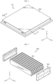
- FIG. 1 is an exploded perspective view showing a battery pack according to the present disclosure.
- FIG. 2 is a perspective view showing the appearance of a battery pack according to the present disclosure.
- the battery pack 10 includes a pack housing 100, a first battery module group 210, a second battery module group 220, and a pack cover 300.
- the pack housing 100 may include a first accommodation space 110, a second accommodation space 120 spaced apart from the first accommodation space 110, and a collection space 130.
- the first accommodation space 110 and the second accommodation space 120 may be configured to accommodate the battery module 200.
- the collection space 130 may be configured to collect a venting gas generated from the battery module 200 to be described below.
- the collection space 130 may be formed between the first accommodation space 110 and the second accommodation space 120.
- the collection space 130 is not limited to only the space formed between the first accommodation space 110 and the second accommodation space 120.
- the collection space 130 may be formed on both sides of the first accommodation space 110 to be described below.
- the collection space 130 may be formed on both sides of the second accommodation space 120, respectively.
- the first battery module group 210 may include a plurality of battery modules 200 arranged in the first accommodation space 110.
- the second battery module group 220 may include a plurality of battery modules 200 disposed in the second accommodation space 120.
- the first battery module group 210 may include four battery modules disposed in the first accommodation space 110, and the second battery module group 220 may include four battery modules disposed in the second accommodation space 120.
- FIGS. 3 and 4 are diagrams showing a battery module included in the battery pack according to the present disclosure.
- the battery module 200 may include a battery cell 201.
- the battery cell 201 may be provided in plurality.
- the battery cell 201 may mean a secondary battery.
- the battery cell 201 may include an electrode assembly, an electrolyte, a battery case accommodating the electrode assembly and the electrolyte, and a pair of electrode leads connected to the electrode assembly and drawn out of the battery case.
- the battery cell 201 may be, for example, a pouch-type secondary battery. However, other types of secondary batteries, such as a cylindrical battery or prismatic battery, may also be employed as the battery cell 201 of the present disclosure.
- the battery module 200 may further include a bus bar frame assembly 202 for electrically connecting the plurality of battery cells 201 to each other.
- the bus bar frame assembly 202 may be provided in a pair, for example. In this case, the pair of bus bar frame assemblies 202 may be coupled to one side and the other side of the longitudinal direction (direction parallel to the X-axis) of the battery cell 201, respectively.
- the battery module 200 may further include a module case 203.
- the module case 203 may be configured to accommodate at least one battery cell 201.
- the module case 203 may include a venting hole 203a. When a venting gas is generated from the battery cell 201 accommodated in the inner space, the venting hole 203a may be configured to discharge the generated venting gas from the inside of the module case 203 to the outside.
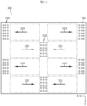
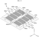
- FIG. 5 is a diagram showing a moving path of a venting gas by a pack cover included in the battery pack according to the present disclosure.
- the pack cover 300 may include a first side venting channel 310 and a second side venting channel 320.
- the first side venting channel 310 may be configured to guide a venting gas generated in the plurality of battery modules 200 included in the first battery module group 210 to the collection space 130.
- the second side venting channel 320 may be configured to guide a venting gas generated in the plurality of battery modules 200 included in the second battery module group 220 to the collection space 130.
- the pack cover 300 may be coupled with the pack housing 100 to form a venting channel between the upper part of the battery module 200 and the inner surface of the pack cover 300.
- the pack cover 300 may include a protrusion unit 330.
- the protrusion unit 330 may be provided on a surface of a region corresponding to the collection space 130.
- the protrusion unit 330 may be configured to protrude from the surface toward the collection space 130.
- this configuration of the present disclosure it is possible to add a function of controlling the flow of a venting gas by creating a venting channel in the pack cover 300, which is used only for covering the pack housing 100 in a general case.
- the flame and venting gas may move to the collection space 130 along the first side venting channel 310 and the second side venting channel 320 formed between the upper part of the battery module 200 and the inner surface of the pack cover 300, whereby the possibility of a thermal event spreading toward adjacent battery modules 200 may be significantly reduced.
- the protrusion unit 330 prevents the venting gas from moving along the shortest straight path.
- the temperature of the venting gas may drop during movement of the venting gas, and even when a flame is generated together with the venting gas, the intensity of the flame may be weakened while moving along the venting channel. Accordingly, it is possible to remove or reduce damage that may occur due to the ejection of high-temperature venting gas and flame to the outside.
- the protrusion unit 330 may include a plurality of protrusions S.
- the plurality of protrusions S may be formed to be spaced apart from each other.
- the plurality of protrusions S may be provided along the extension direction (positive Y-axis direction) of the collection space 130.
- the plurality of protrusions S may be provided along a direction (X-axis extension direction) substantially perpendicular to the extension direction (positive Y-axis direction) of the collection space 130. Referring to FIG. 5 together with FIG. 1 , the plurality of protrusions S may be provided in a region adjacent to the boundary of the first accommodation space 110 and the collection space 130 and a region adjacent to the boundary of the second accommodation space 120 and the collection space 130, respectively.
- the plurality of protrusions S may be provided in two rows along the extension direction (positive Y-axis direction) of the collection space 130 in a region adjacent to the boundary of the first accommodation space 110 and the collection space 130 and a region adjacent to the boundary of the second accommodation space 120 and the collection space 130, respectively.
- the venting gas when the venting gas moves to the collection space 130 through the first side venting channel 310 and the second side venting channel 320, the venting gas directly encounters the plurality of protrusions S. Therefore, the moving path of the venting gas may be effectively increased.
- FIG. 6 is a diagram showing a pack cover included in the battery pack according to the present disclosure.
- the pack cover 300 may include a first side venting channel 310 and a second side venting channel 320 formed in a groove G shape on the inner surface.
- the first side venting channel 310 may be provided in plurality along a direction (positive of Y-axis direction) substantially perpendicular to the extension direction (positive X-axis direction) of the first side venting channel 310.
- the second side venting channels 320 may be provided in plurality along a direction (positive Y-axis direction) substantially perpendicular to the extension direction (negative X-axis direction) of the second side venting channel 320.
- a plurality of grooves G may be provided.
- the pack cover 300 may include a shield 301 configured to block a venting gas from directly moving to the outside through the first side venting channel 310 and the second side venting channel 320 without passing through the collection space 130.
- FIG. 7 is a diagram showing a barrier of the battery pack according to the present disclosure.
- the first battery module group 210 may include a first battery module 211 and a second battery module 212 adjacent to each other.
- the second battery module group 220 may include a third battery module 221 and a fourth battery module 222 adjacent to each other.
- the first battery module 211 and the second battery module 212 do not refer to specific battery modules. That is, the first battery module 211 and the second battery module 212 refer to one and the other of a pair of battery modules randomly selected in the first battery module group 210 and adjacent to each other.
- the third battery module 221 and the fourth battery module 222 do not refer to specific battery modules. That is, the third battery module 221 and the fourth battery module 222 refer to one and the other of a pair of battery modules randomly selected in the second battery module group 220 and adjacent to each other.
- the battery pack 10 may include a first barrier 400a and/or an additional barrier 400b and/or a third barrier 400c.
- the first barrier 400a may be disposed at a corresponding position between the first battery module 211 and the second battery module 212 and at a corresponding position between the third battery module 221 and the fourth battery module 222.
- the first barrier 400a may be configured to block the movement of a venting gas between the accommodation space of the first battery module 211 and the accommodation space of the second battery module 212 and the movement of a venting gas between the accommodation space of the third battery module 221 and the accommodation space of the fourth battery module 222.
- the first barrier 400a may be coupled with the pack cover 300 and/or the pack housing 100. The coupling may be performed by welding, bolting, or the like.
- the first barrier 400a may have an approximate beam shape with an empty inside.
- the first barrier 400a may be disposed at a corresponding position between the plurality of batteries battery modules 200 in the first battery module group 210 and a corresponding position between the plurality of battery modules 200 included in the second battery module group 220.
- the accommodation spaces of battery modules adjacent to each other are structurally isolated from each other by the first barrier 400a, so that the venting gas generated in each battery module does not move toward an adjacent battery module but moves through the first side venting channel 310 and the second side venting channel 320.
- the venting gas moved in this way moves through the collection space 130 again.
- the temperature of the venting gas may be lowered and the intensity of the flame may be weakened.
- the first barrier 400a has an approximate beam shape with an empty inner space, the weight of the battery pack 10 may be reduced in addition to improving the rigidity of the battery pack 10 and blocking the movement of a venting gas between adjacent accommodation spaces.
- the additional barrier 400b may be disposed at a corresponding position between the first accommodation space 110 and the collection space 130 and at a corresponding position between the second accommodation space 120 and the collection space 130, respectively.
- the additional barrier may be configured to block the movement of a venting gas between the first accommodation space 110 and the collection space 130 and between the second accommodation space 120 and the collection space 130.
- the third barrier 400c may be configured to partition the collection space 130.
- the third barrier 400c prevents the venting gas collected through the first side venting channel 310 and the venting gas collected through the second side venting channel 320 from mixing. That is, the third barrier 400c may be configured to prevent the venting gas generated from the first battery module group 210 from affecting the second battery module group 220. Also, the third barrier 400c may be configured to prevent the venting gas generated from the second battery module group 220 from affecting the first battery module group 210.
- the third barrier 400c may be coupled with the pack cover 300 and/or the pack housing 100. The coupling may be performed by welding, bolting, or the like.
- the third barrier 400c may have an approximate beam shape with an empty inside. The empty space formed in the third barrier 400c may be used as a passage through which wires for connecting the battery modules pass. The wiring may be protected from physical impact by the third barrier 400c.
- FIG. 8 is a cross-sectional view schematically showing an exemplary shape of a cross-section taken along line A-A' in FIG. 2 .
- the battery pack 10 may include a sealing member 500.
- the sealing member 500 may be provided in at least one position between the first barrier 400a and the pack cover 300 and between the first barrier 400a and the pack housing 100.
- the sealing member 500 may be provided in at least one position between the additional barrier 400b and the pack cover 300 and between the additional barrier 400b and the pack housing 100.
- the sealing member 500 may be provided in at least one position between the third barrier 400c and the pack cover 300 and between the third barrier 400c and the pack housing 100.
- the sealing member 500 may be configured to at least partially cover the coupling portions of the pack cover 300 and/or the pack housing 100 and the barriers 400a, 400b, 400c.
- the effect of preventing a venting gas from moving into gaps between the pack cover 300 and/or the pack housing 100 and the barriers 400a, 400b, 400c may be further improved.
- FIG. 9 is a diagram showing a pack housing included in the battery pack according to the present disclosure and a battery module accommodated in the pack housing.
- the collection space 130 may include a first collection space 130a formed between the first accommodation space 110 and the second accommodation space 120.
- the collection space 130 may include a second collection space 130b formed at a side opposite to the first collection space 130a with the first accommodation space 110 interposed therebetween.
- the collection space 130 may include a third collection space 130c formed at a side opposite to the first collection space 130a with the second accommodation space 120 interposed therebetween.
- FIG. 10 is a diagram showing a pack cover included in the battery pack according to the present disclosure.
- the protrusion unit 330 may be provided in at least one region among a region corresponding to the first collection space 130a, a region corresponding to the second collection space 130b, and a region corresponding to the third collection space 130c. As shown in FIG. 10 , the protrusion unit 330 may be provided in all of the region corresponding to the first collection space 130a, the region corresponding to the second collection space 130b, and the region corresponding to the third collection space 130c. Unlike this, the protrusion unit 330 may be selectively provided in a part of a region corresponding to at least one collection space 130 as in an embodiment shown below.
- the protrusion unit 330 prevents the venting gas from moving along the shortest straight path. Therefore, by selectively providing the protrusion unit 330 in the pack cover 300 according to the venting channel provided in the pack cover 300, the traveling distance of the venting gas may be varied for each battery module. The venting gas generated from each battery module may be discharged with a time difference.
- FIG. 11 is a diagram showing a moving path of a venting gas by the pack cover included in the battery pack according to the present disclosure.
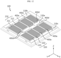
- FIG. 12 is a diagram showing a pack housing included in the battery pack according to the present disclosure and a battery module accommodated in the pack housing.
- FIG. 13 is a diagram showing a pack cover included in the battery pack according to the present disclosure.
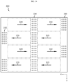
- FIG. 14 is a diagram showing a moving path of a venting gas by the pack cover included in the battery pack according to the present disclosure.
- FIG. 15 is a diagram showing a pack housing included in the battery pack according to the present disclosure and a battery module accommodated in the pack housing.
- FIG. 16 is a diagram showing a pack cover included in the battery pack according to the present disclosure.
- the pack cover 300 may be configured to guide the venting gas generated from the first battery module 211 to the first collection space 130a, guide the venting gas generated from the second battery module 212 to the second collection space 130b, guide the venting gas generated from the third battery module 221 to the first collection space 130a, and guide the venting gas generated from the fourth battery module 222 to the third collection space 130c.
- the first battery module 211 and the second battery module 212 do not refer to specific battery modules, but refer to a pair of battery modules 200 randomly selected from the first battery module group 210 and adjacent to each other. This is also the same for the third battery module 221 and the fourth battery module 222.
- the first battery module 211 and the third battery module 221 may face each other, and the second battery module 212 and the fourth battery module 222 may face each other.
- the first battery module 211 and the fourth battery module 222 may face each other, and the second battery module 212 and the third battery module 221 may face each other.
- the battery pack 10 may include a second barrier 400d as well as the first barrier 400a and/or the third barrier 400c described above.
- the second barrier 400d may be disposed at corresponding positions between the accommodation space accommodating the first battery module 211 and the second collection space 130b, between the accommodation space accommodating the second battery module 212 and the first collection space 130a, between the accommodation space accommodating the third battery module 221 and the third collection space 130c, and between the accommodation space accommodating the fourth battery module 222 and the first collection space 130a, respectively.
- the second barrier 400d may be disposed at corresponding positions between the accommodation space accommodating the first battery module 211 and the second collection space 130b, between the accommodation space of accommodating the second battery module 212 and the first collection space 130a, between the accommodation space accommodating the third battery module 221 and the first collection space 130a, and between the accommodation space accommodating the fourth battery module 222 and the third collection space 130c, respectively.
- the pack cover 300 may include a first side venting channel 310 and a second side venting channel 320 formed in a groove G shape on the inner surface.
- the first side venting channel 310 may be provided in plurality along a direction (Y-axis extension direction) substantially perpendicular to the extension direction (X-axis extension direction) of the first side venting channel 310.
- the second side venting channel 320 may be provided in plurality along a direction (Y-axis extension direction) substantially perpendicular to the extension direction (X-axis extension direction) of the second side venting channel 320.
- the groove G may be provided in plurality.
- the pack cover 300 may include a shield 301.
- the shield 301 may be provided in a boundary region between a region corresponding to the first collection space 130a and the first side venting channel 310. In this case, the communication between the first side venting channel 310 and the first collection space 130a may be blocked.
- the shield 301 may be provided in a boundary region between a region corresponding to the second collection space 130b and the first side venting channel 310. In this case, the communication between the first side venting channel 310 and the second collection space 130b may be blocked.
- the shield 301 may be provided in a boundary region between a region corresponding to the first collection space 130a and the second side venting channel 320.
- the communication between the second side venting channel 320 and the first collection space 130a may be blocked.
- the shield 301 may be provided in a boundary region between a region corresponding to the third collection space 130c and the second side venting channel 320. In this case, the communication between the second side venting channel 320 and the third collection space 130c may be blocked.
- the battery modules adjacent to each other in the first battery module group 210 may configure different venting channels.
- the battery modules adjacent to each other in the second battery module group 220 may configure different venting channels. The effect of high-temperature flame and venting gas generated from adjacent battery modules on other battery modules can be minimized.
- an effective venting channel may be configured.
- FIG. 17 is a diagram showing a gas collection space and a venting device included in the battery pack according to the present disclosure.
- the battery pack 10 may include a gas collection space 600 and/or a venting device 700.
- the gas collection space 600 may be provided to at least one of one side and the other side of the pack housing 100.
- the venting gas generated in each battery module moves through the first side venting channel 310 and the second side venting channel 320 and is collected in the gas collection space 600.
- the gas collection space 600 may be provided at an end of the pack housing 100 in the longitudinal direction (positive Y-axis direction).
- the present disclosure is not limited to the shape, location, and number of the gas collection space 600 shown in FIG. 17 .
- the venting device 700 may be configured to discharge the venting gas in the gas collection space 600 to the outside of the pack housing 100.
- the venting device 700 is formed to penetrate the pack housing 100 and may be in the form of a simple hole.
- the venting device 700 may be a specific device that not only has a completely open form, but also has a form not completely open, but is closed in a normal state and may be opened according to a change in pressure or temperature.
- the venting device 700 may be, for example, a one-way valve.
- the internal pressure of the battery pack 10 when the internal pressure of the battery pack 10 increases since a large amount of gas is generated at once, the internal pressure of the battery pack 10 may be quickly reduced through the gas collection space 600.
- the gas may be discharged in the intended direction through the venting device 700, and even if a lot of venting gas is instantaneously generated, the gas may be discharged more rapidly and smoothly by increasing the processing capacity or number of the venting device 700.
- FIG. 18 is a diagram showing a vehicle according to the present disclosure.
- the battery pack 10 may be applied to a vehicle 1 such as an electric vehicle 1 or a hybrid vehicle 1. That is, the vehicle 1 according to the present disclosure may include the battery pack 10 according to the present disclosure. In addition, the vehicle 1 according to the present disclosure may further include various other components included in a vehicle 1 in addition to the battery pack 10. For example, the vehicle 1 according to the present disclosure may further include a vehicle body, a motor, and a control device such as an electronic control unit (ECU), in addition to the battery pack 10 according to the present disclosure.
- ECU electronice control unit
Landscapes
- Chemical Kinetics & Catalysis (AREA)
- Electrochemistry (AREA)
- General Chemical & Material Sciences (AREA)
- Chemical & Material Sciences (AREA)
- Engineering & Computer Science (AREA)
- Manufacturing & Machinery (AREA)
- Aviation & Aerospace Engineering (AREA)
- Sustainable Development (AREA)
- Power Engineering (AREA)
- Transportation (AREA)
- Mechanical Engineering (AREA)
- Sustainable Energy (AREA)
- Life Sciences & Earth Sciences (AREA)
- Battery Mounting, Suspending (AREA)
- Gas Exhaust Devices For Batteries (AREA)
Abstract
Description
- The present disclosure relates to a battery pack and a vehicle including the same, and more specifically, to a battery pack configured to discharge a high-temperature gas to the outside of the battery pack without affecting other adjacent battery modules when the gas is generated inside the battery module, and a vehicle including the same.
- The present application claims priority to
Korean Patent Application No. 10-2022-0011081 filed on January 25, 2022 - As the demand for portable electronic products such as notebooks, video cameras, and mobile phones rapidly increases and the commercialization of robots and electric vehicles begins in earnest, research on high-performance secondary batteries capable of repeated charging and discharging is being actively conducted.
- Currently commercialized secondary batteries include nickel cadmium batteries, nickel hydrogen batteries, nickel zinc batteries, and lithium secondary batteries. Among them, lithium secondary batteries are in the limelight because of their advantages of free charge and discharge, very low self-discharge rate, and high energy density, as the memory effect hardly occurs compared to nickel-based secondary batteries.
- These lithium secondary batteries mainly use lithium-based oxide and carbon material as a positive electrode active material and a negative electrode active material, respectively. A lithium secondary battery includes an electrode assembly in which a positive electrode plate and a negative electrode plate coated with such a positive electrode active material and a negative electrode active material, respectively, are disposed with a separator therebetween, and an exterior material, that is, a battery case for sealing and accommodating the electrode assembly together with electrolyte.
- In general, lithium secondary batteries may be classified into a can-type secondary battery in which an electrode assembly is embedded in a metal can and a pouch-type secondary battery in which an electrode assembly is embedded in a pouch of an aluminum laminate sheet, depending on the shape of the exterior material.
- Recently, secondary batteries have been widely used for driving or energy storage not only in small devices such as portable electronic devices, but also in medium and large-sized devices such as electric vehicles and energy storage systems (ESSs). Many of these secondary batteries may be accommodated together inside a module case in a state of being electrically connected, which may configure one battery module, and such battery modules may be electrically connected again in a narrow space to increase energy density, which configures a battery pack.
- However, when a plurality of battery modules exist in a dense state in a narrow space as above, they may be vulnerable to accidents such as fire or explosion. For example, when an event such as thermal runaway occurs in one battery module, high-temperature gas may be discharged from the battery module. If this gas is not properly discharged to the outside of the battery pack, the thermal event generated in some battery modules may be propagated to other battery modules provided inside the battery pack, which may cause a chain reaction. Also, in this case, the pressure inside the battery pack increases, and there is a possibility of explosion. When the battery pack explodes, not only great damage may be caused to nearby devices or users due to the pressure of the explosion, but also the range and speed of damage may be further increased. Therefore, it is required to develop a battery pack having a structure that allows the high-temperature gas to be safely discharged to the outside of the battery pack without affecting other adjacent battery modules when an abnormality occurs in some battery modules and a gas is discharged.
- The present disclosure is designed to solve the problems of the related art, and therefore the present disclosure is directed to controlling the flow of a venting gas in a desired direction by adding an additional venting channel formation structure to an existing battery pack.
- In another aspect, the present disclosure is directed to allowing the high-temperature venting gas ejected when a thermal event occurs in some battery modules to be safely discharged to the outside of the battery pack without affecting other battery modules inside the battery pack.
- However, the technical problem to be solved by the present disclosure is not limited to the above-mentioned problems, and other problems not mentioned will be clearly understood by those skilled in the art from the description below.
- In one aspect of the present disclosure, there is provided a battery pack comprising: a pack housing having a first accommodation space, a second accommodation space spaced apart from the first accommodation space, and a collection space; a first battery module group including a plurality of battery modules disposed within the first accommodation space; a second battery module group including a plurality of battery modules disposed within the second accommodation space; and a pack cover including a first side venting channel configured to guide a venting gas generated in the plurality of battery modules included in the first battery module group to the collection space and a second side venting channel configured to guide a venting gas generated in the plurality of battery modules included in the second battery module group to the collection space, wherein the pack cover includes a protrusion unit on a surface of a region corresponding to the collection space.
- The protrusion unit may include a plurality of protrusions configured to protrude on the surface toward the collection space.
- The plurality of protrusions may be formed to be spaced apart from each other.
- The plurality of protrusions may be provided along an extension direction of the collection space
- The plurality of protrusions may be provided along a direction perpendicular to an extension direction of the collection space.
- The plurality of protrusions may be provided in a region adjacent to a boundary between the first accommodation space and the collection space and a region adjacent to a boundary between the second accommodation space and the collection space, respectively.
- The first battery module group may include a first battery module and a second battery module adjacent to each other, and the second battery module group includes a third battery module and a fourth battery module adjacent to each other.
- The battery pack may include a first barrier disposed at a corresponding position between the first battery module and the second battery module and at a corresponding position between the third battery module and the fourth battery module, respectively.
- The first barrier may be configured to block the movement of a venting gas between the accommodation space of the first battery module and the accommodation space of the second battery module and the movement of a venting gas between the accommodation space of the third battery module and the accommodation space of the fourth battery module.
- The battery pack may include a sealing member provided to at least one position between the first barrier and the pack cover and between the first barrier and the pack housing.
- The collection space may include a first collection space formed between the first accommodation space and the second accommodation space.
- The collection space may include a second collection space formed at a side opposite to the first collection space with the first accommodation space interposed therebetween; and a third collection space formed at a side opposite to the first collection space with the second accommodation space interposed therebetween.
- The protrusion unit may be provided in at least one region among a region corresponding to the first collection space, a region corresponding to the second collection space, and a region corresponding to the third collection space.
- The pack cover may be configured to guide a venting gas generated in the first battery module to the first collection space and guide a venting gas generated in the second battery module to the second collection space, and guide a venting gas generated in the third battery module to the first collection space and guide a venting gas generated in the fourth battery module to the third collection space.
- The first battery module and the third battery module may face each other, and the second battery module and the fourth battery module may face each other.
- In an inner space of the pack housing, the battery pack may include a second barrier disposed at corresponding positions between the accommodation space accommodating the first battery module and the second collection space, between the accommodation space accommodating the second battery module and the first collection space, between the accommodation space accommodating the third battery module and the third collection space, and between the accommodation space accommodating the fourth battery module and the first collection space, respectively.
- The first battery module and the fourth battery module may face each other, and the second battery module and the third battery module may face each other.
- In an inner space of the pack housing, the battery pack may include a second barrier disposed at corresponding positions between the accommodation space accommodating the first battery module and the second collection space, between the accommodation space accommodating the second battery module and the first collection space, between the accommodation space accommodating the third battery module and the first collection space, and between the accommodation space accommodating the fourth battery module and the third collection space, respectively.
- The pack housing may have a gas collection space formed in at least one of one side and the other side.
- The pack housing may include a venting device configured to allow the venting gas in the gas collection space to be discharged to the outside of the pack housing.
- A vehicle according to an embodiment of the present disclosure for achieving the above object includes the battery pack according to the present disclosure.
- According to an aspect of the present disclosure, a function for controlling the flow of a venting gas may be added by creating a venting channel in the pack cover, which is used only for covering the pack housing in general. Specifically, according to this configuration of the present disclosure, when a thermal event occurs in each battery module, flame and venting gas move to the collection space along the first side venting channel and the second side venting channel formed between the upper portion of the battery module and the inner surface of the pack cover, thereby significantly reducing the possibility of thermal events spreading toward adjacent battery modules. When the venting gas moves into the collection space, the protrusion unit prevents the venting gas from moving along the shortest straight path. Therefore, the temperature of the venting gas may drop while the venting gas is moving, and even when a flame is generated together with the venting gas, the intensity of the flame may decrease while moving along the venting channel. Accordingly, it is possible to remove or reduce damage that may occur due to the ejection of the high-temperature venting gas and flame to the outside.
- According to another aspect of the present disclosure, when the venting gas moves to the collection space through the first side venting channel and the second side venting channel, it directly encounters a plurality of protrusions. Therefore, the moving path of the venting gas can be effectively increased.
- According to another aspect of the present disclosure, the accommodation spaces of the first battery modules adjacent to each other and the accommodation spaces of the second battery modules adjacent to each other are structurally isolated from each other by a first barrier. Thus, the venting gas generated in each battery module does not move toward adjacent battery modules, but moves through the first side venting channel and the second side venting channel. The venting gas moved in this way moves again through the collection space. During this movement, the temperature of the venting gas may be lowered and the intensity of the flame may be weakened. If the first barrier has an approximate beam shape with an empty inner space, it is possible to not only improve the stiffness of the battery pack and block the movement of the venting gas between adjacent accommodation spaces, but also reduce the weight of the battery pack.
- According to another aspect of the present disclosure, the effect of preventing the venting gas from moving into the gap between the barrier and the pack cover and/or the pack housing may be further improved.
- According to another aspect of the present disclosure, when the venting gas moves to the collection space by applying the protrusion unit, it is possible to prevent the venting gas from moving along the shortest straight path. For example, by selectively applying a protrusion unit to the venting channels provided in the pack cover, the venting gas travel distance can be varied for each battery module. Accordingly, the venting gas generated from each battery module can be discharged with a time difference.
- According to another aspect of the present disclosure, a plurality of first battery modules adjacent to each other may configure different venting channels. A plurality of second battery modules adjacent to each other may configure different venting channels. Therefore, it is possible to minimize the effect of high-temperature flame and venting gas generated in an adjacent battery module on other battery modules.
- According to another aspect of the present disclosure, an effective venting channel can be configured according to the size of a battery pack and the arrangement of battery modules.
- According to another aspect of the present disclosure, when a large amount of gas is generated at once to increase the internal pressure of the battery pack, the internal pressure of the battery pack may be quickly reduced through a gas collection space. The gas may be discharged in an intended direction through the venting device, and even if a lot of venting gas is instantaneously generated, the gas may be discharged more rapidly and smoothly by increasing the process capacity or number of venting devices.
- However, the technical problem to be solved by the present disclosure is not limited to the above-mentioned problem, and other problems not mentioned will be clearly understood by those skilled in the art from the description of the invention described below.
- The accompanying drawings illustrate a preferred embodiment of the present disclosure and together with the foregoing disclosure, serve to provide further understanding of the technical features of the present disclosure, and thus, the present disclosure is not construed as being limited to the drawing.
-
FIG. 1 is an exploded perspective view showing a battery pack according to the present disclosure. -
FIG. 2 is a perspective view showing the appearance of a battery pack according to the present disclosure. -
FIGS. 3 and4 are diagrams showing a battery module included in the battery pack according to the present disclosure. -
FIG. 5 is a diagram showing a moving path of a venting gas by a pack cover included in the battery pack according to the present disclosure. -
FIG. 6 is a diagram showing a pack cover included in the battery pack according to the present disclosure. -
FIG. 7 is a diagram showing a barrier of the battery pack according to the present disclosure. -
FIG. 8 is a cross-sectional view schematically showing an exemplary shape of a cross-section taken along line A-A' inFIG. 2 . -
FIG. 9 is a diagram showing a pack housing included in the battery pack according to the present disclosure and a battery module accommodated in the pack housing. -
FIG. 10 is a diagram showing a pack cover included in the battery pack according to the present disclosure. -
FIG. 11 is a diagram showing a moving path of a venting gas by the pack cover included in the battery pack according to the present disclosure. -
FIG. 12 is a diagram showing a pack housing included in the battery pack according to the present disclosure and a battery module accommodated in the pack housing. -
FIG. 13 is a diagram showing a pack cover included in the battery pack according to the present disclosure. -
FIG. 14 is a diagram showing a moving path of a venting gas by the pack cover included in the battery pack according to the present disclosure. -
FIG. 15 is a diagram showing a pack housing included in the battery pack according to the present disclosure and a battery module accommodated in the pack housing. -
FIG. 16 is a diagram showing a pack cover included in the battery pack according to the present disclosure. -
FIG. 17 is a diagram showing a collection space and a venting device included in the battery pack according to the present disclosure. -
FIG. 18 is a diagram showing a vehicle according to the present disclosure. - Hereinafter, preferred embodiments of the present disclosure will be described in detail with reference to the accompanying drawings. The accompanying drawings illustrate a preferred embodiment of the present disclosure and together with the foregoing disclosure, serve to provide further understanding of the technical features of the present disclosure, and thus, the present disclosure is not construed as being limited to the drawing. Like reference signs designate like components. Also, in the drawings, the thickness, ratio, and dimensions of components may be exaggerated for effective description of technical content.
- It should be understood that the terms used in the specification and the appended claims should not be construed as limited to general and dictionary meanings, but interpreted based on the meanings and concepts corresponding to technical aspects of the present disclosure on the basis of the principle that the inventor is allowed to define terms appropriately for the best explanation.
- In this specification, terms indicating directions such as up, down, left, right, front, and back are used, but these terms are only for convenience of explanation, and it is apparent to those skilled in the art that the terms may vary depending on the location of the target object or the location of the observer.
- Therefore, the description proposed herein is just a preferable example for the purpose of illustrations only, not intended to limit the scope of the disclosure, so it should be understood that other equivalents and modifications could be made thereto without departing from the scope of the disclosure.
-
FIG. 1 is an exploded perspective view showing a battery pack according to the present disclosure.FIG. 2 is a perspective view showing the appearance of a battery pack according to the present disclosure. - Referring to
FIGS. 1 and2 , thebattery pack 10 according to the present disclosure includes apack housing 100, a firstbattery module group 210, a secondbattery module group 220, and apack cover 300. - The
pack housing 100 may include afirst accommodation space 110, asecond accommodation space 120 spaced apart from thefirst accommodation space 110, and acollection space 130. Thefirst accommodation space 110 and thesecond accommodation space 120 may be configured to accommodate thebattery module 200. Thecollection space 130 may be configured to collect a venting gas generated from thebattery module 200 to be described below. Thecollection space 130 may be formed between thefirst accommodation space 110 and thesecond accommodation space 120. However, in the present disclosure, thecollection space 130 is not limited to only the space formed between thefirst accommodation space 110 and thesecond accommodation space 120. For example, thecollection space 130 may be formed on both sides of thefirst accommodation space 110 to be described below. Similarly, thecollection space 130 may be formed on both sides of thesecond accommodation space 120, respectively. - The first
battery module group 210 may include a plurality ofbattery modules 200 arranged in thefirst accommodation space 110. The secondbattery module group 220 may include a plurality ofbattery modules 200 disposed in thesecond accommodation space 120. For example, as shown inFIG. 1 , the firstbattery module group 210 may include four battery modules disposed in thefirst accommodation space 110, and the secondbattery module group 220 may include four battery modules disposed in thesecond accommodation space 120. -
FIGS. 3 and4 are diagrams showing a battery module included in the battery pack according to the present disclosure. - Referring to
FIG. 3 , thebattery module 200 may include abattery cell 201. Thebattery cell 201 may be provided in plurality. Thebattery cell 201 may mean a secondary battery. Thebattery cell 201 may include an electrode assembly, an electrolyte, a battery case accommodating the electrode assembly and the electrolyte, and a pair of electrode leads connected to the electrode assembly and drawn out of the battery case. Thebattery cell 201 may be, for example, a pouch-type secondary battery. However, other types of secondary batteries, such as a cylindrical battery or prismatic battery, may also be employed as thebattery cell 201 of the present disclosure. - When the
battery cell 201 is provided in plurality, the plurality ofbattery cells 201 may be electrically connected. Thebattery module 200 may further include a busbar frame assembly 202 for electrically connecting the plurality ofbattery cells 201 to each other. The busbar frame assembly 202 may be provided in a pair, for example. In this case, the pair of busbar frame assemblies 202 may be coupled to one side and the other side of the longitudinal direction (direction parallel to the X-axis) of thebattery cell 201, respectively. - Referring to
FIG. 4 , thebattery module 200 may further include amodule case 203. Themodule case 203 may be configured to accommodate at least onebattery cell 201. Themodule case 203 may include aventing hole 203a. When a venting gas is generated from thebattery cell 201 accommodated in the inner space, theventing hole 203a may be configured to discharge the generated venting gas from the inside of themodule case 203 to the outside. -
FIG. 5 is a diagram showing a moving path of a venting gas by a pack cover included in the battery pack according to the present disclosure. - Referring to
FIG. 5 , thepack cover 300 may include a firstside venting channel 310 and a secondside venting channel 320. - The first
side venting channel 310 may be configured to guide a venting gas generated in the plurality ofbattery modules 200 included in the firstbattery module group 210 to thecollection space 130. - The second
side venting channel 320 may be configured to guide a venting gas generated in the plurality ofbattery modules 200 included in the secondbattery module group 220 to thecollection space 130. - The
pack cover 300 may be coupled with thepack housing 100 to form a venting channel between the upper part of thebattery module 200 and the inner surface of thepack cover 300. - The
pack cover 300 may include aprotrusion unit 330. - The
protrusion unit 330 may be provided on a surface of a region corresponding to thecollection space 130. Theprotrusion unit 330 may be configured to protrude from the surface toward thecollection space 130. - According to this configuration of the present disclosure, it is possible to add a function of controlling the flow of a venting gas by creating a venting channel in the
pack cover 300, which is used only for covering thepack housing 100 in a general case. Specifically, according to this configuration of the present disclosure, when a thermal event occurs in eachbattery module 200, the flame and venting gas may move to thecollection space 130 along the firstside venting channel 310 and the secondside venting channel 320 formed between the upper part of thebattery module 200 and the inner surface of thepack cover 300, whereby the possibility of a thermal event spreading towardadjacent battery modules 200 may be significantly reduced. When the venting gas moves to thecollection space 130, theprotrusion unit 330 prevents the venting gas from moving along the shortest straight path. Thus, the temperature of the venting gas may drop during movement of the venting gas, and even when a flame is generated together with the venting gas, the intensity of the flame may be weakened while moving along the venting channel. Accordingly, it is possible to remove or reduce damage that may occur due to the ejection of high-temperature venting gas and flame to the outside. - Referring back to
FIG. 5 , theprotrusion unit 330 may include a plurality of protrusions S. - The plurality of protrusions S may be formed to be spaced apart from each other. The plurality of protrusions S may be provided along the extension direction (positive Y-axis direction) of the
collection space 130. The plurality of protrusions S may be provided along a direction (X-axis extension direction) substantially perpendicular to the extension direction (positive Y-axis direction) of thecollection space 130. Referring toFIG. 5 together withFIG. 1 , the plurality of protrusions S may be provided in a region adjacent to the boundary of thefirst accommodation space 110 and thecollection space 130 and a region adjacent to the boundary of thesecond accommodation space 120 and thecollection space 130, respectively. For example, the plurality of protrusions S may be provided in two rows along the extension direction (positive Y-axis direction) of thecollection space 130 in a region adjacent to the boundary of thefirst accommodation space 110 and thecollection space 130 and a region adjacent to the boundary of thesecond accommodation space 120 and thecollection space 130, respectively. - According to this configuration of the present disclosure, when the venting gas moves to the
collection space 130 through the firstside venting channel 310 and the secondside venting channel 320, the venting gas directly encounters the plurality of protrusions S. Therefore, the moving path of the venting gas may be effectively increased. -
FIG. 6 is a diagram showing a pack cover included in the battery pack according to the present disclosure. - Referring to
FIG. 6 together withFIG. 5 , thepack cover 300 may include a firstside venting channel 310 and a secondside venting channel 320 formed in a groove G shape on the inner surface. The firstside venting channel 310 may be provided in plurality along a direction (positive of Y-axis direction) substantially perpendicular to the extension direction (positive X-axis direction) of the firstside venting channel 310. The secondside venting channels 320 may be provided in plurality along a direction (positive Y-axis direction) substantially perpendicular to the extension direction (negative X-axis direction) of the secondside venting channel 320. To this end, a plurality of grooves G may be provided. Thepack cover 300 may include ashield 301 configured to block a venting gas from directly moving to the outside through the firstside venting channel 310 and the secondside venting channel 320 without passing through thecollection space 130. -
FIG. 7 is a diagram showing a barrier of the battery pack according to the present disclosure. - Referring to
FIG. 7 , the firstbattery module group 210 may include afirst battery module 211 and asecond battery module 212 adjacent to each other. The secondbattery module group 220 may include athird battery module 221 and afourth battery module 222 adjacent to each other. - In the present disclosure, the
first battery module 211 and thesecond battery module 212 do not refer to specific battery modules. That is, thefirst battery module 211 and thesecond battery module 212 refer to one and the other of a pair of battery modules randomly selected in the firstbattery module group 210 and adjacent to each other. Thethird battery module 221 and thefourth battery module 222 do not refer to specific battery modules. That is, thethird battery module 221 and thefourth battery module 222 refer to one and the other of a pair of battery modules randomly selected in the secondbattery module group 220 and adjacent to each other. - The
battery pack 10 may include afirst barrier 400a and/or anadditional barrier 400b and/or athird barrier 400c. - The
first barrier 400a may be disposed at a corresponding position between thefirst battery module 211 and thesecond battery module 212 and at a corresponding position between thethird battery module 221 and thefourth battery module 222. Thefirst barrier 400a may be configured to block the movement of a venting gas between the accommodation space of thefirst battery module 211 and the accommodation space of thesecond battery module 212 and the movement of a venting gas between the accommodation space of thethird battery module 221 and the accommodation space of thefourth battery module 222. Thefirst barrier 400a may be coupled with thepack cover 300 and/or thepack housing 100. The coupling may be performed by welding, bolting, or the like. Thefirst barrier 400a may have an approximate beam shape with an empty inside. - However, as described above, since the
first battery module 211, thesecond battery module 212, thethird battery module 221, and thefourth battery module 222 do not refer to specific battery modules, thefirst barrier 400a may be disposed at a corresponding position between the plurality ofbatteries battery modules 200 in the firstbattery module group 210 and a corresponding position between the plurality ofbattery modules 200 included in the secondbattery module group 220. - According to this configuration of the present disclosure, the accommodation spaces of battery modules adjacent to each other are structurally isolated from each other by the
first barrier 400a, so that the venting gas generated in each battery module does not move toward an adjacent battery module but moves through the firstside venting channel 310 and the secondside venting channel 320. The venting gas moved in this way moves through thecollection space 130 again. During this movement, the temperature of the venting gas may be lowered and the intensity of the flame may be weakened. When thefirst barrier 400a has an approximate beam shape with an empty inner space, the weight of thebattery pack 10 may be reduced in addition to improving the rigidity of thebattery pack 10 and blocking the movement of a venting gas between adjacent accommodation spaces. - The
additional barrier 400b may be disposed at a corresponding position between thefirst accommodation space 110 and thecollection space 130 and at a corresponding position between thesecond accommodation space 120 and thecollection space 130, respectively. The additional barrier may be configured to block the movement of a venting gas between thefirst accommodation space 110 and thecollection space 130 and between thesecond accommodation space 120 and thecollection space 130. - The
third barrier 400c may be configured to partition thecollection space 130. Thethird barrier 400c prevents the venting gas collected through the firstside venting channel 310 and the venting gas collected through the secondside venting channel 320 from mixing. That is, thethird barrier 400c may be configured to prevent the venting gas generated from the firstbattery module group 210 from affecting the secondbattery module group 220. Also, thethird barrier 400c may be configured to prevent the venting gas generated from the secondbattery module group 220 from affecting the firstbattery module group 210. Thethird barrier 400c may be coupled with thepack cover 300 and/or thepack housing 100. The coupling may be performed by welding, bolting, or the like. Thethird barrier 400c may have an approximate beam shape with an empty inside. The empty space formed in thethird barrier 400c may be used as a passage through which wires for connecting the battery modules pass. The wiring may be protected from physical impact by thethird barrier 400c. -
FIG. 8 is a cross-sectional view schematically showing an exemplary shape of a cross-section taken along line A-A' inFIG. 2 . - Referring to
FIG. 8 , thebattery pack 10 may include a sealingmember 500. - The sealing
member 500 may be provided in at least one position between thefirst barrier 400a and thepack cover 300 and between thefirst barrier 400a and thepack housing 100. The sealingmember 500 may be provided in at least one position between theadditional barrier 400b and thepack cover 300 and between theadditional barrier 400b and thepack housing 100. The sealingmember 500 may be provided in at least one position between thethird barrier 400c and thepack cover 300 and between thethird barrier 400c and thepack housing 100. The sealingmember 500 may be configured to at least partially cover the coupling portions of thepack cover 300 and/or thepack housing 100 and thebarriers - According to this configuration of the present disclosure, the effect of preventing a venting gas from moving into gaps between the
pack cover 300 and/or thepack housing 100 and thebarriers -
FIG. 9 is a diagram showing a pack housing included in the battery pack according to the present disclosure and a battery module accommodated in the pack housing. - Referring to
FIG. 9 , thecollection space 130 may include afirst collection space 130a formed between thefirst accommodation space 110 and thesecond accommodation space 120. Thecollection space 130 may include asecond collection space 130b formed at a side opposite to thefirst collection space 130a with thefirst accommodation space 110 interposed therebetween. Thecollection space 130 may include athird collection space 130c formed at a side opposite to thefirst collection space 130a with thesecond accommodation space 120 interposed therebetween. -
FIG. 10 is a diagram showing a pack cover included in the battery pack according to the present disclosure. - Referring to
FIG. 10 , theprotrusion unit 330 may be provided in at least one region among a region corresponding to thefirst collection space 130a, a region corresponding to thesecond collection space 130b, and a region corresponding to thethird collection space 130c. As shown inFIG. 10 , theprotrusion unit 330 may be provided in all of the region corresponding to thefirst collection space 130a, the region corresponding to thesecond collection space 130b, and the region corresponding to thethird collection space 130c. Unlike this, theprotrusion unit 330 may be selectively provided in a part of a region corresponding to at least onecollection space 130 as in an embodiment shown below. - According to this configuration of the present disclosure, when a venting gas moves to the
collection space 130, theprotrusion unit 330 prevents the venting gas from moving along the shortest straight path. Therefore, by selectively providing theprotrusion unit 330 in thepack cover 300 according to the venting channel provided in thepack cover 300, the traveling distance of the venting gas may be varied for each battery module. The venting gas generated from each battery module may be discharged with a time difference. -
FIG. 11 is a diagram showing a moving path of a venting gas by the pack cover included in the battery pack according to the present disclosure.FIG. 12 is a diagram showing a pack housing included in the battery pack according to the present disclosure and a battery module accommodated in the pack housing.FIG. 13 is a diagram showing a pack cover included in the battery pack according to the present disclosure.FIG. 14 is a diagram showing a moving path of a venting gas by the pack cover included in the battery pack according to the present disclosure.FIG. 15 is a diagram showing a pack housing included in the battery pack according to the present disclosure and a battery module accommodated in the pack housing.FIG. 16 is a diagram showing a pack cover included in the battery pack according to the present disclosure. - Referring to
FIGS. 11 to 16 , thepack cover 300 may be configured to guide the venting gas generated from thefirst battery module 211 to thefirst collection space 130a, guide the venting gas generated from thesecond battery module 212 to thesecond collection space 130b, guide the venting gas generated from thethird battery module 221 to thefirst collection space 130a, and guide the venting gas generated from thefourth battery module 222 to thethird collection space 130c. - However, as described above, the
first battery module 211 and thesecond battery module 212 do not refer to specific battery modules, but refer to a pair ofbattery modules 200 randomly selected from the firstbattery module group 210 and adjacent to each other. This is also the same for thethird battery module 221 and thefourth battery module 222. - Referring to
FIG. 12 , thefirst battery module 211 and thethird battery module 221 may face each other, and thesecond battery module 212 and thefourth battery module 222 may face each other. - Referring to
FIG. 15 , thefirst battery module 211 and thefourth battery module 222 may face each other, and thesecond battery module 212 and thethird battery module 221 may face each other. - Referring to
FIGS. 12 and15 together withFIG. 9 , thebattery pack 10 may include asecond barrier 400d as well as thefirst barrier 400a and/or thethird barrier 400c described above. - Referring to
FIG. 12 , in the inner space of thepack housing 100 of thebattery pack 10, thesecond barrier 400d may be disposed at corresponding positions between the accommodation space accommodating thefirst battery module 211 and thesecond collection space 130b, between the accommodation space accommodating thesecond battery module 212 and thefirst collection space 130a, between the accommodation space accommodating thethird battery module 221 and thethird collection space 130c, and between the accommodation space accommodating thefourth battery module 222 and thefirst collection space 130a, respectively. - Referring to
FIG. 15 , in the inner space of thepack housing 100, thesecond barrier 400d may be disposed at corresponding positions between the accommodation space accommodating thefirst battery module 211 and thesecond collection space 130b, between the accommodation space of accommodating thesecond battery module 212 and thefirst collection space 130a, between the accommodation space accommodating thethird battery module 221 and thefirst collection space 130a, and between the accommodation space accommodating thefourth battery module 222 and thethird collection space 130c, respectively. - Referring to
FIGS. 13 and16 , similarly to the above description, thepack cover 300 may include a firstside venting channel 310 and a secondside venting channel 320 formed in a groove G shape on the inner surface. The firstside venting channel 310 may be provided in plurality along a direction (Y-axis extension direction) substantially perpendicular to the extension direction (X-axis extension direction) of the firstside venting channel 310. The secondside venting channel 320 may be provided in plurality along a direction (Y-axis extension direction) substantially perpendicular to the extension direction (X-axis extension direction) of the secondside venting channel 320. To this end, the groove G may be provided in plurality. - Referring back to
FIGS. 13 and16 , similarly to the above description, thepack cover 300 may include ashield 301. Theshield 301 may be provided in a boundary region between a region corresponding to thefirst collection space 130a and the firstside venting channel 310. In this case, the communication between the firstside venting channel 310 and thefirst collection space 130a may be blocked. Theshield 301 may be provided in a boundary region between a region corresponding to thesecond collection space 130b and the firstside venting channel 310. In this case, the communication between the firstside venting channel 310 and thesecond collection space 130b may be blocked. Theshield 301 may be provided in a boundary region between a region corresponding to thefirst collection space 130a and the secondside venting channel 320. In this case, the communication between the secondside venting channel 320 and thefirst collection space 130a may be blocked. Theshield 301 may be provided in a boundary region between a region corresponding to thethird collection space 130c and the secondside venting channel 320. In this case, the communication between the secondside venting channel 320 and thethird collection space 130c may be blocked. - According to this configuration of the present disclosure, the battery modules adjacent to each other in the first
battery module group 210 may configure different venting channels. The battery modules adjacent to each other in the secondbattery module group 220 may configure different venting channels. The effect of high-temperature flame and venting gas generated from adjacent battery modules on other battery modules can be minimized. Depending on the size of thebattery pack 10 and the arrangement of battery modules, an effective venting channel may be configured. -
FIG. 17 is a diagram showing a gas collection space and a venting device included in the battery pack according to the present disclosure. - Referring to
FIG. 17 , thebattery pack 10 may include agas collection space 600 and/or aventing device 700. - The
gas collection space 600 may be provided to at least one of one side and the other side of thepack housing 100. The venting gas generated in each battery module moves through the firstside venting channel 310 and the secondside venting channel 320 and is collected in thegas collection space 600. For example, thegas collection space 600 may be provided at an end of thepack housing 100 in the longitudinal direction (positive Y-axis direction). However, the present disclosure is not limited to the shape, location, and number of thegas collection space 600 shown inFIG. 17 . - The
venting device 700 may be configured to discharge the venting gas in thegas collection space 600 to the outside of thepack housing 100. Theventing device 700 is formed to penetrate thepack housing 100 and may be in the form of a simple hole. In addition, theventing device 700 may be a specific device that not only has a completely open form, but also has a form not completely open, but is closed in a normal state and may be opened according to a change in pressure or temperature. Theventing device 700 may be, for example, a one-way valve. - According to this configuration of the present disclosure, when the internal pressure of the
battery pack 10 increases since a large amount of gas is generated at once, the internal pressure of thebattery pack 10 may be quickly reduced through thegas collection space 600. The gas may be discharged in the intended direction through theventing device 700, and even if a lot of venting gas is instantaneously generated, the gas may be discharged more rapidly and smoothly by increasing the processing capacity or number of theventing device 700. -
FIG. 18 is a diagram showing a vehicle according to the present disclosure. - Referring to
FIG. 18 , thebattery pack 10 may be applied to a vehicle 1 such as an electric vehicle 1 or a hybrid vehicle 1. That is, the vehicle 1 according to the present disclosure may include thebattery pack 10 according to the present disclosure. In addition, the vehicle 1 according to the present disclosure may further include various other components included in a vehicle 1 in addition to thebattery pack 10. For example, the vehicle 1 according to the present disclosure may further include a vehicle body, a motor, and a control device such as an electronic control unit (ECU), in addition to thebattery pack 10 according to the present disclosure. - As described above, the present disclosure has been described based on preferred embodiments with reference to the accompanying drawings, but it is clear that many various and obvious modifications can be made from this description to those skilled in the art without departing from the scope of the present disclosure. Accordingly, the scope of the present disclosure should be construed by the claims described to include such many modified examples.
-
- 1: vehicle
- 10 : battery pack
- 100 : pack housing
- 110 : first accommodation space
- 120 : second accommodation space
- 130 : collection space
- 130a : first collection space
- 130b : second collection space
- 130c : third collection space
- 200 : battery module
- 201 : battery cell
- 202 : bus bar frame assembly
- 203 : module case
- 203a : venting hole
- 210 : first battery module group
- 211 : first battery module
- 212 : second battery module
- 220 : second battery module group
- 221 : third battery module
- 222 : fourth battery module
- 300 : pack cover
- 301 : shield
- 310 : first side venting channel
- 320 : second side venting channel
- 330 : protrusion unit
- 400a : first barrier
- 400b : additional barrier
- 400c : third barrier
- 400d : second barrier
- 500 : sealing member
- 600 : gas collection space
- 700 : venting device
- S : plurality of protrusions
- G : groove
Claims (20)
- A battery pack comprising:a pack housing having a first accommodation space, a second accommodation space spaced apart from the first accommodation space, and a collection space;a first battery module group including a plurality of battery modules disposed within the first accommodation space;a second battery module group including a plurality of battery modules disposed within the second accommodation space; anda pack cover including a first side venting channel configured to guide a venting gas generated in the plurality of battery modules included in the first battery module group to the collection space and a second side venting channel configured to guide a venting gas generated in the plurality of battery modules included in the second battery module group to the collection space,wherein the pack cover includes a protrusion unit on a surface of a region corresponding to the collection space.
- The battery pack according to claim 1, wherein the protrusion unit includes a plurality of protrusions configured to protrude on the surface toward the collection space.
- The battery pack according to claim 2, wherein the plurality of protrusions are formed to be spaced apart from each other.
- The battery pack according to claim 3, wherein the plurality of protrusions are provided along an extension direction of the collection space
- The battery pack according to claim 3, wherein the plurality of protrusions are provided along a direction perpendicular to an extension direction of the collection space.
- The battery pack according to claim 3, wherein the plurality of protrusions are provided in a region adjacent to a boundary between the first accommodation space and the collection space and a region adjacent to a boundary between the second accommodation space and the collection space, respectively.
- The battery pack according to claim 1, wherein the first battery module group includes a first battery module and a second battery module adjacent to each other, and the second battery module group includes a third battery module and a fourth battery module adjacent to each other, and
wherein the battery pack includes a first barrier disposed at a corresponding position between the first battery module and the second battery module and at a corresponding position between the third battery module and the fourth battery module, respectively. - The battery pack according to claim 7, wherein the first barrier is configured to block the movement of a venting gas between the accommodation space of the first battery module and the accommodation space of the second battery module and the movement of a venting gas between the accommodation space of the third battery module and the accommodation space of the fourth battery module.
- The battery pack according to claim 8, wherein the battery pack includes a sealing member provided to at least one position between the first barrier and the pack cover and between the first barrier and the pack housing.
- The battery pack according to claim 1, wherein the collection space includes a first collection space formed between the first accommodation space and the second accommodation space.
- The battery pack according to claim 10, wherein the collection space includes:a second collection space formed at a side opposite to the first collection space with the first accommodation space interposed therebetween; anda third collection space formed at a side opposite to the first collection space with the second accommodation space interposed therebetween.
- The battery pack according to claim 11, wherein the protrusion unit is provided in at least one region among a region corresponding to the first collection space, a region corresponding to the second collection space, and a region corresponding to the third collection space.
- The battery pack according to claim 11, wherein the first battery module group includes a first battery module and a second battery module adjacent to each other, and the second battery module group includes a third battery module and a fourth battery module adjacent to each other, and
wherein the pack cover is configured to:guide a venting gas generated in the first battery module to the first collection space and guide a venting gas generated in the second battery module to the second collection space, andguide a venting gas generated in the third battery module to the first collection space and guide a venting gas generated in the fourth battery module to the third collection space. - The battery pack according to claim 13, wherein the first battery module and the third battery module face each other, and the second battery module and the fourth battery module face each other.
- The battery pack according to claim 14, wherein, in an inner space of the pack housing, the battery pack includes a second barrier disposed at corresponding positions between the accommodation space accommodating the first battery module and the second collection space, between the accommodation space accommodating the second battery module and the first collection space, between the accommodation space accommodating the third battery module and the third collection space, and between the accommodation space accommodating the fourth battery module and the first collection space, respectively.
- The battery pack according to claim 13, wherein the first battery module and the fourth battery module face each other, and the second battery module and the third battery module face each other.
- The battery pack according to claim 16, wherein in an inner space of the pack housing, the battery pack includes a second barrier disposed at corresponding positions between the accommodation space accommodating the first battery module and the second collection space, between the accommodation space accommodating the second battery module and the first collection space, between the accommodation space accommodating the third battery module and the first collection space, and between the accommodation space accommodating the fourth battery module and the third collection space, respectively.
- The battery pack according to claim 1, wherein the pack housing has a gas collection space formed in at least one of one side and the other side.
- The battery pack according to claim 18, wherein the pack housing includes a venting device configured to allow the venting gas in the gas collection space to be discharged to the outside of the pack housing.
- A vehicle, comprising the battery pack according to any one of claims 1 to 19.
Applications Claiming Priority (2)
| Application Number | Priority Date | Filing Date | Title |
|---|---|---|---|
| KR20220011081 | 2022-01-25 | ||
| PCT/KR2023/001146 WO2023146278A1 (en) | 2022-01-25 | 2023-01-25 | Battery pack and vehicle comprising same |
Publications (2)
| Publication Number | Publication Date |
|---|---|
| EP4379934A1 true EP4379934A1 (en) | 2024-06-05 |
| EP4379934A4 EP4379934A4 (en) | 2025-03-05 |
Family
ID=87472041
Family Applications (1)
| Application Number | Title | Priority Date | Filing Date |
|---|---|---|---|
| EP23747319.4A Pending EP4379934A4 (en) | 2022-01-25 | 2023-01-25 | BATTERY PACK AND VEHICLE COMPRISING IT |
Country Status (7)
| Country | Link |
|---|---|
| US (1) | US12315953B2 (en) |
| EP (1) | EP4379934A4 (en) |
| JP (1) | JP7797644B2 (en) |
| KR (1) | KR102767821B1 (en) |
| CN (1) | CN118369813A (en) |
| CA (1) | CA3241411A1 (en) |
| WO (1) | WO2023146278A1 (en) |
Families Citing this family (9)
| Publication number | Priority date | Publication date | Assignee | Title |
|---|---|---|---|---|
| US20240039112A1 (en) * | 2022-08-01 | 2024-02-01 | Ford Global Technologies, Llc | Traction battery pack venting system and venting method |
| KR102870479B1 (en) * | 2023-09-08 | 2025-10-15 | 주식회사 엘지에너지솔루션 | Battery pack |
| CN120642118A (en) * | 2023-09-08 | 2025-09-12 | 株式会社Lg新能源 | battery pack |
| CN117374508B (en) * | 2023-12-07 | 2024-03-01 | 蜂巢能源科技股份有限公司 | Battery and battery pack |
| KR102840487B1 (en) * | 2023-12-13 | 2025-07-29 | 주식회사 엘지에너지솔루션 | Battery pack |
| KR20250094161A (en) * | 2023-12-18 | 2025-06-25 | 주식회사 엘지에너지솔루션 | Battery pack and top cover for battery pack |
| KR20250158327A (en) | 2024-04-30 | 2025-11-06 | 주식회사 엘지에너지솔루션 | Battery pack |
| KR20250159463A (en) | 2024-05-02 | 2025-11-11 | 주식회사 엘지에너지솔루션 | Battery pack |
| WO2026029484A1 (en) * | 2024-07-31 | 2026-02-05 | 주식회사 엘지에너지솔루션 | Battery pack and vehicle including same |
Family Cites Families (24)
| Publication number | Priority date | Publication date | Assignee | Title |
|---|---|---|---|---|
| JP2011204577A (en) | 2010-03-26 | 2011-10-13 | Panasonic Corp | Battery pack |
| WO2015045401A1 (en) * | 2013-09-30 | 2015-04-02 | パナソニックIpマネジメント株式会社 | Battery-affixing frame member, battery-affixing member, and electricity storage device |
| JP2016122543A (en) | 2014-12-24 | 2016-07-07 | トヨタ自動車株式会社 | Battery cooling device |
| KR101799238B1 (en) | 2017-06-09 | 2017-11-17 | 김국현 | Battery cover assembly |
| DE102017212223A1 (en) * | 2017-07-18 | 2019-01-24 | Bayerische Motoren Werke Aktiengesellschaft | BATTERY OF AN ELECTRICALLY DRIVEN MOTOR VEHICLE |
| US20190173074A1 (en) | 2017-12-04 | 2019-06-06 | Kabushiki Kaisha Toshiba | Battery |
| CN111771297B (en) * | 2018-03-12 | 2023-07-11 | 松下知识产权经营株式会社 | Exhaust duct for battery pack and battery pack |
| WO2020039626A1 (en) | 2018-08-22 | 2020-02-27 | ビークルエナジージャパン株式会社 | Battery pack |
| DE112019005702T5 (en) | 2018-11-13 | 2021-07-29 | Rivian Ip Holdings, Llc | Reduction of thermal runaway in battery cell packs |
| US10950833B2 (en) | 2018-12-28 | 2021-03-16 | Caterpillar Inc. | Battery packaging assembly with safety features to reduce thermal propagation |
| CN111384328A (en) | 2018-12-29 | 2020-07-07 | 比亚迪股份有限公司 | Battery trays, power battery packs and vehicles |
| CN109686891B (en) * | 2019-01-16 | 2025-03-11 | 郑州比克新能源汽车有限公司 | A wind-liquid integrated battery pack |
| CN110444835B (en) | 2019-08-29 | 2021-07-20 | 蜂巢能源科技有限公司 | Battery packs and vehicles |
| CN112331981B (en) | 2019-10-15 | 2021-09-17 | 宁德时代新能源科技股份有限公司 | Battery pack and vehicle |
| CN210576235U (en) * | 2019-10-22 | 2020-05-19 | 黄宗洪 | Active positive pressure oxygen supply system of metal-air battery stack |
| CN110739424A (en) | 2019-10-28 | 2020-01-31 | 广州小鹏汽车科技有限公司 | A battery box and a battery box thermal runaway monitoring method |
| US11316230B1 (en) * | 2019-11-27 | 2022-04-26 | Zoox, Inc. | Battery thermal mitigation venting |
| KR102885905B1 (en) * | 2020-04-20 | 2025-11-12 | 주식회사 엘지에너지솔루션 | A battery module having a flame discharge prevention structure, and a battery pack and Energy storagy system including the battery module |
| KR20210130443A (en) | 2020-04-22 | 2021-11-01 | 주식회사 엘지에너지솔루션 | Battery module and battery pack including the same |
| KR102665192B1 (en) * | 2020-04-29 | 2024-05-09 | 주식회사 엘지에너지솔루션 | Battery pack and device including the same |
| JP7496725B2 (en) | 2020-07-20 | 2024-06-07 | 東京エレクトロン株式会社 | Etching method and etching apparatus |
| CN112670634A (en) | 2020-12-21 | 2021-04-16 | 广州橙行智动汽车科技有限公司 | Battery module and car |
| KR102857933B1 (en) * | 2020-12-24 | 2025-09-10 | 에스케이온 주식회사 | Battery pack case, and Battery pack having the same |
| PL4270622T3 (en) * | 2022-04-25 | 2025-05-05 | Samsung Sdi Co., Ltd. | Battery pack and electric vehicle |
-
2023
- 2023-01-25 EP EP23747319.4A patent/EP4379934A4/en active Pending
- 2023-01-25 JP JP2024530004A patent/JP7797644B2/en active Active
- 2023-01-25 CA CA3241411A patent/CA3241411A1/en active Pending
- 2023-01-25 CN CN202380015057.6A patent/CN118369813A/en active Pending
- 2023-01-25 US US18/832,057 patent/US12315953B2/en active Active
- 2023-01-25 WO PCT/KR2023/001146 patent/WO2023146278A1/en not_active Ceased
- 2023-01-25 KR KR1020230009754A patent/KR102767821B1/en active Active
Also Published As
| Publication number | Publication date |
|---|---|
| WO2023146278A1 (en) | 2023-08-03 |
| CN118369813A (en) | 2024-07-19 |
| CA3241411A1 (en) | 2023-08-03 |
| US20240421425A1 (en) | 2024-12-19 |
| KR102767821B1 (en) | 2025-02-14 |
| EP4379934A4 (en) | 2025-03-05 |
| US12315953B2 (en) | 2025-05-27 |
| KR20230114735A (en) | 2023-08-01 |
| JP7797644B2 (en) | 2026-01-13 |
| JP2024540619A (en) | 2024-10-31 |
Similar Documents
| Publication | Publication Date | Title |
|---|---|---|
| US12315953B2 (en) | Battery pack and vehicle including the same | |
| EP4383432A1 (en) | Battery pack and vehicle comprising same | |
| EP4391190A1 (en) | Battery pack and vehicle comprising same | |
| KR20230099609A (en) | Battery pack and Vehicle comprising the same | |
| US12283712B2 (en) | Battery pack and vehicle including the same | |
| US20250149729A1 (en) | Battery pack and vehicle including the same | |
| KR20220080623A (en) | Battery Module, Battery Pack, and Vehicle | |
| KR20250042536A (en) | Battery module | |
| EP4708456A1 (en) | Battery pack | |
| EP4576381A1 (en) | Battery pack and vehicle comprising same | |
| EP4730537A1 (en) | Battery pack | |
| CN117203841A (en) | Battery pack and vehicle including the battery pack | |
| KR20250054581A (en) | Battery pack | |
| KR20240074454A (en) | Battery module with reinforced safety |
Legal Events
| Date | Code | Title | Description |
|---|---|---|---|
| STAA | Information on the status of an ep patent application or granted ep patent |
Free format text: STATUS: THE INTERNATIONAL PUBLICATION HAS BEEN MADE |
|
| PUAI | Public reference made under article 153(3) epc to a published international application that has entered the european phase |
Free format text: ORIGINAL CODE: 0009012 |
|
| STAA | Information on the status of an ep patent application or granted ep patent |
Free format text: STATUS: REQUEST FOR EXAMINATION WAS MADE |
|
| 17P | Request for examination filed |
Effective date: 20240229 |
|
| AK | Designated contracting states |
Kind code of ref document: A1 Designated state(s): AL AT BE BG CH CY CZ DE DK EE ES FI FR GB GR HR HU IE IS IT LI LT LU LV MC ME MK MT NL NO PL PT RO RS SE SI SK SM TR |
|
| REG | Reference to a national code |
Ref country code: DE Ref legal event code: R079 Free format text: PREVIOUS MAIN CLASS: H01M0050300000 Ipc: H01M0050367000 |
|
| A4 | Supplementary search report drawn up and despatched |
Effective date: 20250130 |
|
| RIC1 | Information provided on ipc code assigned before grant |
Ipc: H01M 10/625 20140101ALI20250124BHEP Ipc: H01M 50/383 20210101ALI20250124BHEP Ipc: H01M 10/052 20100101ALI20250124BHEP Ipc: H01M 50/204 20210101ALI20250124BHEP Ipc: H01M 10/613 20140101ALI20250124BHEP Ipc: H01M 50/209 20210101ALI20250124BHEP Ipc: H01M 50/271 20210101ALI20250124BHEP Ipc: H01M 50/35 20210101ALI20250124BHEP Ipc: H01M 50/24 20210101ALI20250124BHEP Ipc: H01M 50/30 20210101ALI20250124BHEP Ipc: H01M 50/367 20210101AFI20250124BHEP |
|
| DAV | Request for validation of the european patent (deleted) | ||
| DAX | Request for extension of the european patent (deleted) | ||
| STAA | Information on the status of an ep patent application or granted ep patent |
Free format text: STATUS: EXAMINATION IS IN PROGRESS |
|
| 17Q | First examination report despatched |
Effective date: 20251007 |